

Northern Lights M864 User Manual
M864
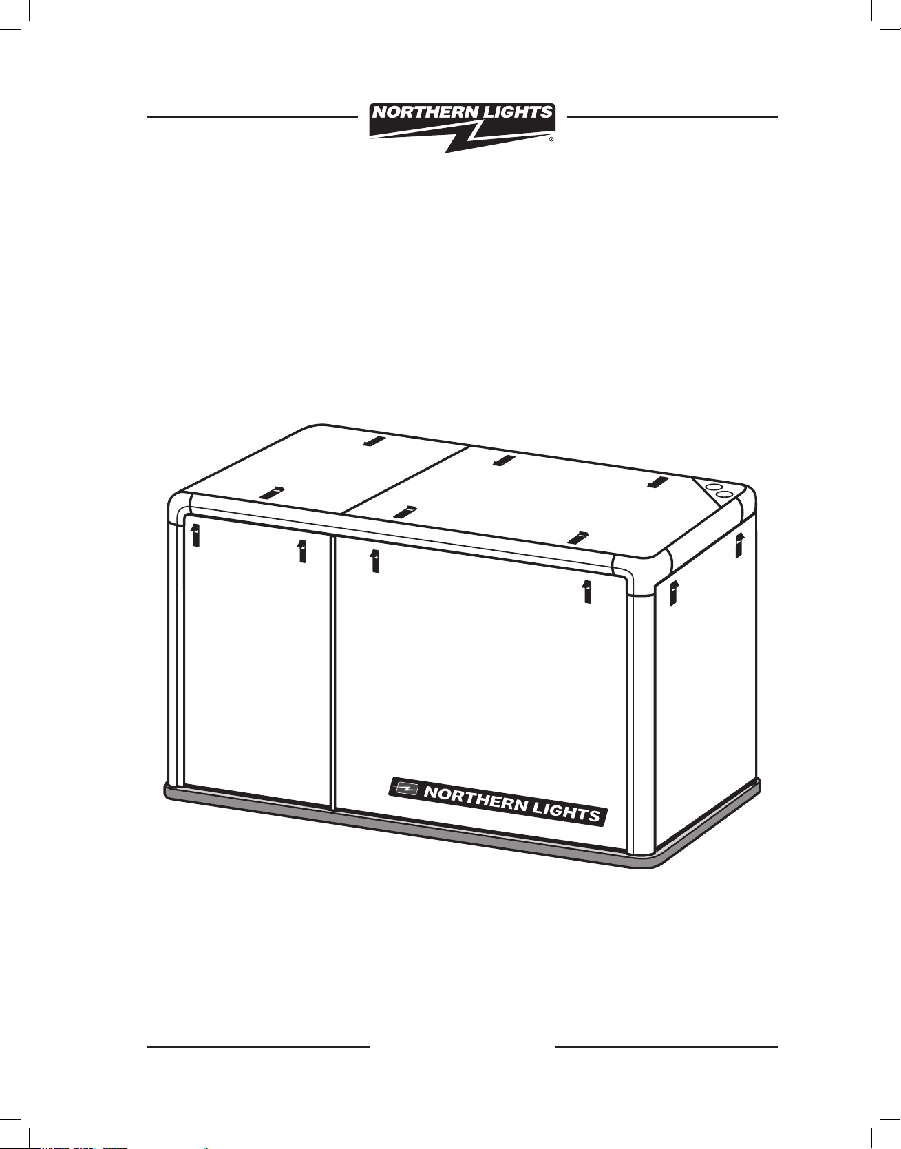
Soundshield Assembly Instructions
Corporate Headquarters
4420 14th Avenue N.W.
Seattle, WA 98107
Tel: (206) 789-3880
Fax: (206) 782-5455
Alaska Branch Office
1200 West Int’l Airport Road
P.O. Box 190208
Anchorage, AK 99519
Tel: (907) 562-2222
Fax: (907) 563-1921
www.northern-lights.com
Southeastern U.S.A.
1415 S.W. 6th Court
Pompano Beach, FL 33069
Tel: (954) 946-7601
Fax: (954) 946-7409
East Coast Branch
Northern Lights Industrial Park
8 Connector Road
Andover, MA 01810
Tel: (978) 475-7400
Fax: (978) 475-7745

L616 04/05

M864 Soundshield Part Number: 05-78705
ITEM # DESCRIPTION P/N QTY NOTES
1. Base board 05-78733 1
2. Extrusion, vertical 05-78702 4
3. Extrusion, horizontal, sides 05-78703 2
4. Extrusion, horizontal, ends 05-78734 2
5. Center post, top 05-78736 1
6. Center post, vertical 05-78706 2
7. Corner casting 05-70001 4
8. Bolting assembly 00-75714 22
9. Tie bracket 23-78701 2
10. Rear panel assembly 05-78742 1
11. Front panel assembly 05-78737 1
12. LH side panel forward assembly 05-78739 1 with vent box
13. LH side panel aft assembly 05-78728 1
14. RH side panel forward assembly 05-78729 1 no vent box
15. RH side panel aft assembly 05-78731 1
16. Top panel forward assembly 05-78747 1
17. Top panel aft assembly 05-78752 1
18. Penetration panel assembly 39-78008 1
19. Panel retainer bracket, 30R 23-70036 6
20. #10 screw s/s x 5/8” long 12-72002 12
21. Toe bracket, 30R 23-70038 4
22. Hex nut, nylock 1/4-20 14-00112 10
Specifications
Enclosure:
Length (OA) 52.65 in (1337 mm)
Width 26.88 in (682.7 mm)
Height 28.16 in (715 mm)
Base:
Length 53.15 in (1350 mm)
Width 27.38 in (695.4 mm)
Height 0.75 in (19.05 mm)
Assembled Height:
28.91 in (734 mm)
Assembled Weight (est):
140 lbs (63.5 kg)
1
1
Prior to assembly, inspect all components for damage. Report any damage to the
shipping company. Check the packing list to be sure all parts have been included.
2
3
Select a mounting location in accordance with the guidelines in the IM1000 Installation Manual (supplied with the generator set). The generator set must typically be
mounted on a rigid, flat surface above a strong structure, such as the vessel’s stringers, to minimize vibration transference to the hull. CAUTION: THE BASEBOARD
IS A NON-STRUCTURAL MATERIAL AND MUST BE FULLY SUPPORTED TO
MINIMIZE FLEX.
Note that the generator set is designed for single side service. When viewed from
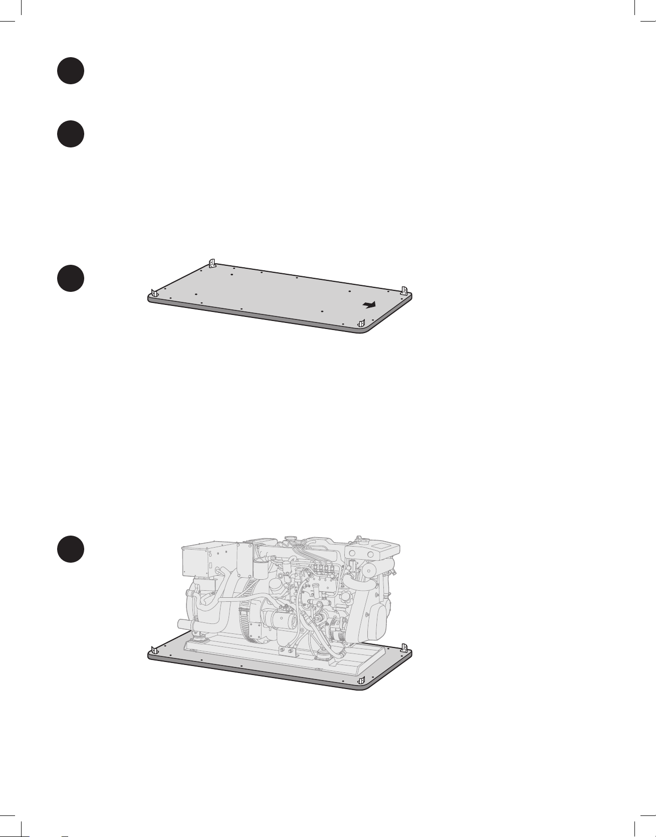
Install the base board (item 1) in the vessel in as near a level attitude as possible.
Observe the arrow symbol on the board’s topside surface. This indicates the top and
forward end orientation of the genset / soundshield. Make sure arrow is correctly
positioned or the unit will not mount correctly within the shield.
4
Install toe bracket (item 21) to each corner of the base board with screws (item 20)
into pre-drilled holes. See figure 1.
Note that there are pre-drilled “through” holes on each side of the baseboard. Use
these holes as guides to drill into the supporting substructure for through-bolting.
Place the generator set onto the baseboard, lining up the thru-holes with the mounting holes in the genset base frame. Use 3/8” or 9 mm bolts of appropriate length to
secure the genset and baseboard to the underlying structure.
2
 Loading...