

Northern Lights M1064D, M1064T2, M1064A, M1064T1, M1066A2 Owner's Manual
...
OPERATOR’S
MANUAL
OM2-2
For Models:
M1064A, M1064D, M1064T1, M1064T2,
M1066A1, M1066A2, M1066A3, M1066T,
M40C2, M55C2, M65C2, & M99C2
— CALIFORNIA —
Proposition 65 Warning:
Diesel engine exhaust and some of its constitu-
ents are known to the State of California to cause
cancer, birth defects, and other reproductive harm.
Northern Lights
4420 14th Avenue N.W.
Seattle, WA 98107
Tel: (206) 789-3880
Fax: (206) 782-5455
Copyright ©2013 Northern Lights, Inc.
All rights reserved. Northern Lights™, and
the Northern Lights logo are trademarks of
Northern Lights, Inc.
Printed in U.S.A.
PART NO.: OM2-2 1/17

OPERATOR'S MANUAL
#OM2-2 for Models:
M1064A, M1064D, M1064T1, M1064T2, M1066A1, M1066A2,
M1066A3, M1066T, M40C2, M55C2, M65C2, and M99C2
Read this operator's manual thoroughly before starting to operate your equipment.
This manual contains information you will need to run and service your new unit.
Table of Contents
INTRODUCTION ..................................................2
Models Included .................................................2
Model Numbers ..................................................2
Serial Numbers ...................................................2
WARRANTY ...........................................................3
SAFETY RULES ..............................................3 - 7
Lockout / Tag Out Procedures ...................... 8
COMPONENT LOCATIONS
M1064 .............................................................. 10
M1066 ...............................................................11
M40C2 ............................................................. 12
ENGINE & GENERATOR CONTROL PANELS
Series 3B & 4B ........................................ 13 - 14
Emission-Related Installation Instructions . 15
OPERATING PROCEDURES
Before Starting ................................................. 15
Shutdown Procedures ...................................... 15
Break-In Period ................................................ 16
SERVICING SCHEDULE CHARTS ...... 17 - 18
SERVICING
Lubrication - General ....................................... 19
Checking Oil .................................................... 19
Oil Changes ..................................................... 19
Changing Oil Filter .......................................... 19
Air Filter .......................................................... 19
Valve Clearances .............................................. 20
Fuels - General ................................................. 21
Crankshaft Vibration Damper (6 Cyl.) ............ 22
Fuel Filters .................................................22- 23
Bleeding the Fuel System ................................ 23
Injector Service ........................................ 23 - 25
Injection Pump ......................................... 25 - 27
Turbocharger .................................................... 28
Turbo Boost ..................................................... 28
Cooling System - General ................................ 28
Engine Coolant Specications ................. 28 - 29
Cooling System Flushing ................................. 30
Heat Exchanger Cleaning ................................ 30
Zinc Electrodes ........................................ 30 - 31
Raw Water Pump ............................................. 31
Generator Ends ................................................ 31
Electrical System - General ............................. 31
Booster Batteries .............................................. 32
Battery Care ..................................................... 32
Winterizing / Out-of-Service ........................... 32
TROUBLESHOOTING
Electrical .......................................................... 32
Engine ...................................................... 33 - 34
WIRING DIAGRAMS
AC Wiring ................................................ 35 - 37
DC Wiring ................................................ 38 - 48
Panel Wiring .......................................49 - 51
ON-BOARD SPARE PARTS ........................... 52
Proprietary Information
This publication is the property of Northern Lights, Inc.
It may not be reproduced in whole or in part without the written permission of Northern Lights, Inc.
© Northern Lights, Inc. All rights reserved. Litho U.S.A. Publication number OM2-2 1/17
OM2-2 1/17
1

Introduction
Servicing of marine engines and generator sets
presents unique problems. In many cases boats cannot
be moved to a repair facility. Marine engines cannot
Failures begin with minor problems that are overlooked
and become amplied when not corrected during
routine maintenance.
be compared to the servicing of automobiles, trucks or
even farm equipment. Failures often occur in remote
areas far from competent assistance. Marine engines
are taxed far more severely than auto or truck engines;
therefore, maintenance schedules must be adhered to
more strictly.
As operator, it is your obligation to learn about your
equipment and its proper maintenance. This is not a
comprehensive technical service manual. Nor will it
make the reader into an expert mechanic. Its aim is to
aid you in maintaining your unit properly.
Model Numberss
Model numbers give the unit's application, block model, aspiration, and RPM:
M
M - Northern Lights marine generator set
M1064A
Northern Lights® aftercooled, 1800 RPM
=
marine diesel generator set with a John Deere
Powertech Tier II 4045 engine block with an
electronically controlled fuel system.
106 mm bore, 4 Cylinder
+
or
106 mm bore, 6 Cylinder
1064 or 1066
Model number
M1066T
Northern Lights® turbocharged marine
generator set with a John Deere Powertech
=
Tier II 6068 engine block with an electronically
controlled fuel system.
A, D, & T
A - Aftercooled
D - Naturally aspirated
+
T - Turbocharged
M1064D
M1064T1
M1064T2
M1066A1
Northern Lights® naturally aspirated, 1800
RPM marine diesel generator set with a John
=
Deere Powertech Tier II 4045 engine block
with a mechanically controlled fuel system.
Northern Lights® turbocharged marine
generator set with a John Deere Powertech
=
Tier II 4045 engine block with a mechanically
controlled fuel system.
Northern Lights® turbocharged marine
generator set with a John Deere Powertech
=
Tier II 4045 engine block with an electronically
controlled fuel system.
Northern Lights® aftercooled marine generator
set with a John Deere Powertech Tier II 6068
=
series 1 engine block with an electronically
controlled fuel system.
MP40C2
MP55C2
MP65C2
MP99C2
40 kW Northern Lights® commercial marine
generator set with a John Deere Powertech
=
Tier II 4045 engine block with a mechanically
controlled fuel system.
55 kW Northern Lights® commercial marine
=
generator set with a John Deere Powertech
Tier II 4045 engine block and a mechanically
controlled fuel system.
65 kW Northern Lights® commercial marine
generator set with a John Deere Powertech
=
Tier II 6068 engine block and an electronically
controlled fuel system.
99 kW Northern Lights® commercial marine
=
generator with a John Deere Powertech Tier
II 6068 engine block and an electronically
controlled fuel system.
Serial Numberss
When referencing Northern Lights equipment by serial number, please refer only to the number
stamped on the Northern Lights® serial number plate.
OM2-2 1/17
2
Revised 4-10-12
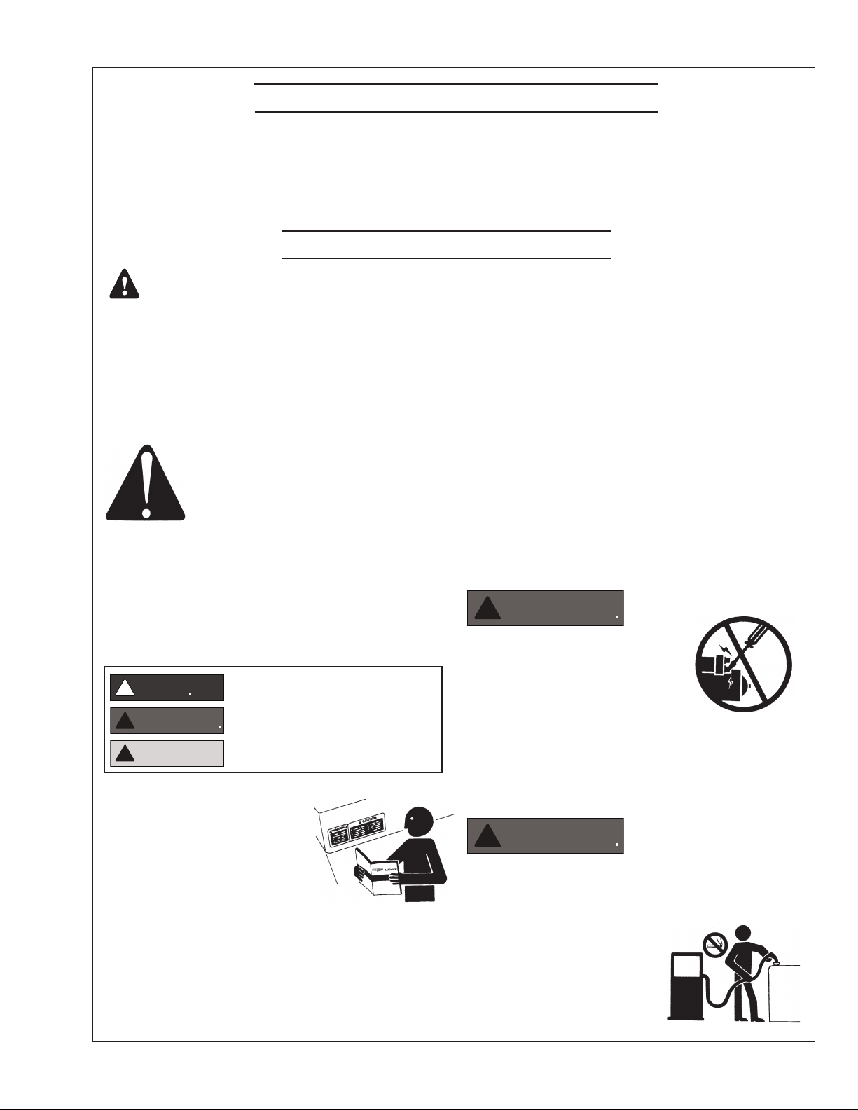
WARNING
WARNING
DANGER
WARNING
!
CAUTION
Warranty
A warranty registration certicate is supplied
with your set. The extent of coverage is described
in the Limited Warranty Statement. We recommend
that you study the statement carefully.
Safety Rules
NOTICE: Accident reports show that careless use of engines causes a high percentage of accidents.
You can avoid accidents by observing these safety rules. Study these rules carefully and enforce them on the job.
IMPORTANT SAFETY INSTRUCTIONS.
Electromagnetic equipment, including generator sets
and their accessories, can cause bodily harm and
life threatening injuries when improperly installed,
operated or maintained. To prevent accidents be aware
of potential dangers and act safely.
READ AND FOLLOW ALL SAFETY
INSTRUCTIONS IN THIS MANUAL,
PRIOR TO THE INSTALLATION
OF ANY GENERATOR SET OR
ACCESSORY. KEEP THESE
INSTRUCTIONS FOR FUTURE
REFERENCE.
Recognize Safety Symbols and Instructions
In addition to the information found in this section, this
operator’s manual uses three dierent signal words to
outline potential dangers of a specic nature.
!
!
DANGER indicates a hazardous situation which, if
not avoided, will result in death or serious injury.
WARNING indicates a hazardous situation which, if
not avoided, could result in death or serious injury.
CAUTION indicates a hazardous situation which,
if not avoided, could result in minor or moderate
injury.
NOTE: If the warranty is to apply, the servicing
instructions outlined in this manual must be
followed. If further information is needed, please
contact an authorized dealer or the factory.
on parts and components from outside suppliers
that is not reproduced in this manual. Consult the
suppliers for additional safety information.
Learn how to operate the machine and how to use
the controls properly. Only trained personnel should
operate machines, or work on or around them.
Keep you machine in proper working condition.
UNAUTHORIZED MODIFICATIONS TO THE
MACHINERY MAY IMPAIR ITS FUNCTION
AND SAFETY PARAMETERS.
Prevent Bypass and Accidental Starting
!
Do not start engine by shorting
across start terminal. Engine will
start if normal circuitry is bypassed,
creating a hazard by runaway
machinery.
Start engine only from operator’s station.
Follow All Safety Instructions
Carefully read and understand
all safety messages in this
manual and on your machine’s
safety signs. Keep signs in good
and clean condition. Replace
missing or damaged signs. Be
sure new equipment components and repair parts
include the current safety signs. For replacement signs,
proper placement of safety signs or clarication on any
safety issue, consult your Northern Lights dealer or the
factory.
There can be additional safety information contained
OM2-2 1/17
Handle Fuel Safely - Avoid Flames
!
Diesel is highly ammable and should be treated
with care at all times. Do do not refuel while
smoking or when near sparks or open ame.
ALWAYS STOP ENGINE
BEFORE FUELING
MACHINE. Always ll
portable fuel tank outdoors.
Never fuel a hot engine.
3
Revised 4-10-12
CAUTION
DANGER
DANGER
WARNING
Safety Rules (Continued)
Prevent accidental discharge of starting uids by
storing all cans in a cool, safe place, away from sparks
or open ame. Store with cap securely on container.
Never incinerate or puncture a fuel container.
Prevent res by keeping machine clean of accumulated
trash, grease and debris. Always clean any spilled fuel
as swiftly as possible. Do not store oily rags, which
can ignite and burn spontaneously.
Be prepared if a re starts. Keep a rst aid kit and re
extinguisher handy. Keep emergency contact numbers
for re department, doctors, ambulance and hospital
near the telephone.
Service Machines Safely
!
Do not wear a necktie, scarf,
necklace, rings or other
jewelry, or any loose clothing
when working near moving
parts. Tie long hair behind your head. If any of these
items get caught in moving machinery, severe injury or
death could result.
Check for any loose electrical connections or faulty
wiring.
Look completely around engine to make sure that
everything is clear before starting.
Operating equipment requires the full attention of
the operator. Do not use radio or music headphones
while operating machinery.
Practice Safe Maintenance
!
Understand all service procedures
before starting work. Keep area clean and dry.
Never lubricate, service, or adjust machine while it is
in operation.
Keep hands, feet and clothing away from powerdriven equipment. When shutting down an engine,
disengage all power and operator controls. Allow
the engine to cool completely before beginning any
service work.
Securely support any machinery elements that must
be raised for service work with support or lifting
machinery specically intended for that purpose.
Keep all parts in good conditions and properly
installed. Fix damage immediately. Replace any
worn or broken parts. Remove any build up of
grease, oil or debris.
Disconnect battery ground cable (-) before making
any adjustments or service work.
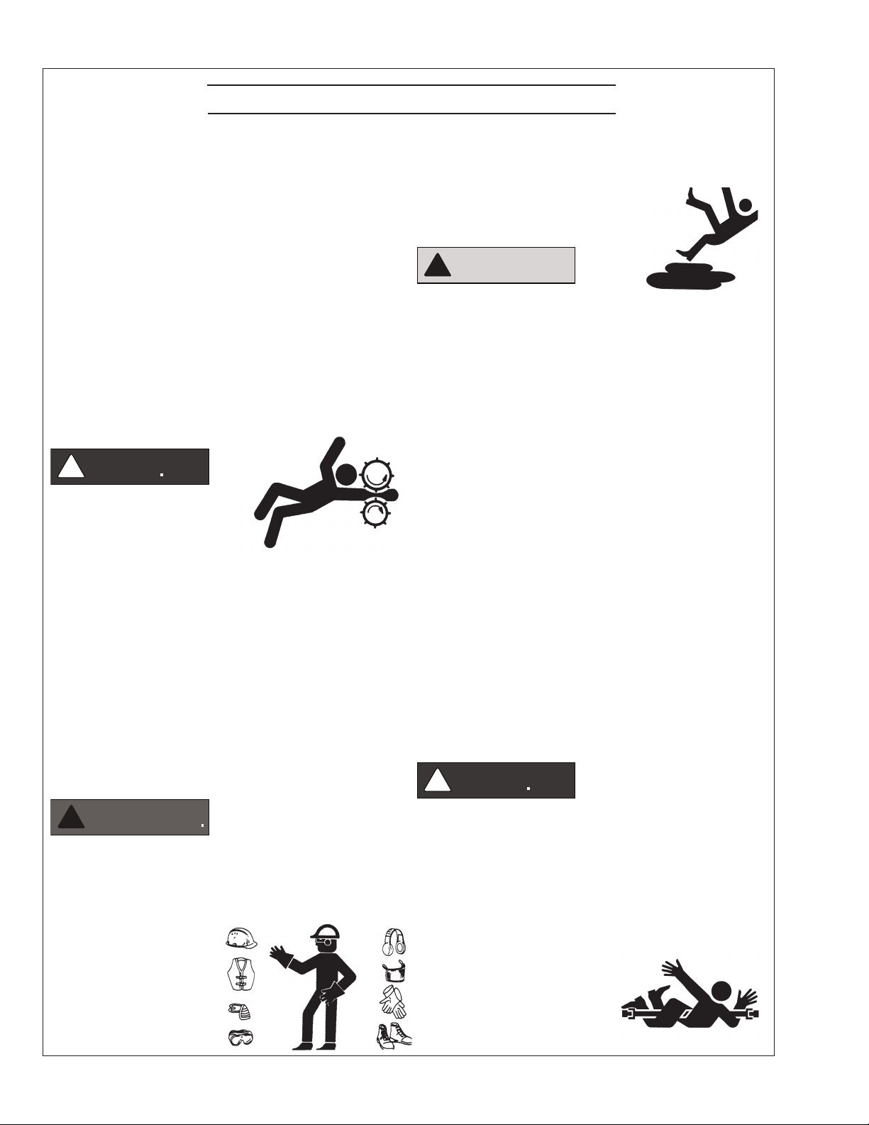
Stay Clear of Rotating Drivelines
Wear Protective Clothing
!
To prevent catching anything in moving machinery,
always wear close tting clothes and safety equipment
appropriate to the job.
Prolonged exposure to loud noise can cause hearing
loss or impairment.
Wear suitable authorized
hearing protection, such
as earmus or plugs to
protect against loud noises.
Entanglement in rotating drivelines can cause serious
injury or death. Keep shields in place at all times.
Make sure that rotating shields turn freely in pace
with the drivelines.
Do not wear loose tting equipment around rotating
drivelines. Stop the engine and make sure that all
moving parts have stopped
before making any adjustments,
connections, or performing
any other type of service to
the engine or other driven
equipment.
OM2-2 1/17
4
!

Revised 7-9-12
WARNING
WARNING
WARNING
WARNING
Safety Rules (Continued)
Install all Safety Guards
!
Direct contact with rotating
fans, belts, pulley and drives
can cause serious injury.
Keep all guards in place at all
times during engine operation.
Wear close-tting clothes. Stop the engine and be
sure all fans, belts, pulleys and drives are stopped
before making adjustments, connections, or cleaning
near fans and their components.
Do not allow anything on your person to dangle into
or come in contact with a moving fan, belt, pulley or
drive. Fans can act as vacuums and pull materials
up from below, so avoid that area as well while in
service.
Safe Battery Handling
To Avoid Hazards:
• Fill batteries only in well-ventilated areas.
• Wear appropriate eye protection and rubber gloves.
• Never use air pressure to clean batteries.
• Wear appropriate ventilation equipment to avoid
inhaling fumes when adding electrolyte.
• Do not spill or drip electrolyte.
• Use correct jump-start procedure if required.
If acid is spilled on skin or in eyes:
1. Flush skin with water.
2. Apply baking soda or lime to
help neutralize acid.
3. Flush eyes with water for
15-30 minutes.
4. Get medical attention
immediately.
If acid is swallowed:
1. DO NOT induce vomiting.
2. Drink large amounts of
water or milk, without
exceeding 2 liters
(2 quarts)
3. Get medical attention immediately
!
Prevent Battery Explosions
Battery gas is highly
ammable. Battery
explosions can cause severe
injury or death. To help
prevent battery explosions, keep sparks, lighted
matches and open ame away from the top of battery.
When checking battery electrolyte level, use a
ashlight.
Never check battery charge by contacting the posts
with a metal object. Use a volt-meter or hydrometer.
Frozen batteries may explode if charged. Never
charge a battery that has not been allowed to warm to
at least 16oC (60oF).
Always remove grounded (-) battery clamp rst and
replace ground clamp last.
ulfuric acid in battery electrolyte is poisonous and
S
strong enough to burn skin, eat holes into clothing and
other materials, and cause blindness if splashed into eyes.
!
Battery posts, terminals, and related accessories
can contain lead and lead compounds, chemicals
known to the State of California to cause cancer and
reproductive harm. Wash hands after handling.
Handle Chemical Products Safely
!
Direct exposure to hazardous
chemicals can cause serious injury.
Among the potentially hazardous
chemicals that may be used
with Northern Lights
products are lubricants,
coolants, paints and adhesives.
All potentially hazardous chemicals come with a Material
Safety Data Sheet (MSDS). The MSDS provides specic
details on chemical products, including physical hazards,
safety procedures and emergency response techniques
OM2-2 1/17
5
Revised 4-10-12
CAUTION
WARNING
WARNING
WARNING
WARNING
DANGER
Safety Rules (Continued)
Read and understand the MSDS for each chemical before
you start any job that includes it. Follow the procedures
and use appropriate equipment exactly as recommended.
Contact your Northern Lights dealer or Northern Lights
factory for MSDS’s used on Northern Lights products.
Work in Well Ventilated Areas
!
Exhaust fumes from engines contain carbon monoxide
and can cause sickness or death. Work in well ventilated
areas to avoid prolonged exposure to engine fumes. If it
is necessary to run an engine in an enclosed area, route
the exhaust fumes out of the area with an approved, leak
proof exhaust pipe extension.
Remove Paint Before Welding or Heating
!
Hazardous fumes can be generated
when paint is heated by welding,
soldering or using a torch. To avoid
potentially toxic fumes and dust,
remove paint before heating.
Remove paint a minimum of 100
•
mm (4 in.) from the
area that will be aected by heat.
•
If paint cannot be removed, wear an approved respirator.
• If you sand or grind paint, use an approved respirator.
• If you use solvent or paint stripper, remove stripper
with soap and water before welding. Remove
solvent or paint stripper containers from the area.
• Allow at least 15 minutes for fumes to disperse
before welding or heating.
Do not use a chlorinated solvent in an area where welding
will occur. Work only in areas that are well ventilated.
Dispose of paint and solvent properly.
engine has been shut o. Do not remove a ller cap
unless it
hands. Slowly loosen cap to relieve pressure before
opening fully.
Avoid High Pressure Fluids
is cool enough to comfortably grip with bare
!
Relieve pressure prior to
disconnecting pressurized lines.
Escaping uid under pressure
can penetrate the skin causing
serious injury. Always relieve pressure before
disconnecting hydraulic or other pressurized lines.
Tighten all connections rmly before re-applying
pressure.
If searching for leaks, use a piece of cardboard.
Always protect your hands and other body parts from
high-pressure uids.
If an accident occurs, see a doctor immediately. Any
high pressure spray injected into the skin must be
removed within a few hours to prevent the risk of
gangrene or other infection.
Avoid Heating Near Pressurized Fluid Lines
!
Flammable spray can be generated
by heating near pressurized uid
lines, resulting in severe burns and
bodily injury. Pressurized lines
can rupture when heat goes beyond the immediate
ame area. Do not weld, solder or use a torch or
open ame near pressurized lines or other ammable
uids.
Do Not Open High-Pressure Fuel System
Service Cooling System Safely
!
Opening a pressurized cooling
system can release explosive
uids and causing serious burns.
Before opening any pressurized
cooling system, make sure the
!
Many Northern Lights engines use high-pressure
fuel injection. High-pressure uid remaining in fuel
lines can cause serious injury. Do not disconnect or
attempt any repair of fuel lines, sensors, or other
OM2-2 1/17
6
Revised 4-10-12
WARNING
!
CAUTION
!
CAUTION
WARNING
WARNING
Safety Rules (Continued)
components between the high-pressure fuel pump
and nozzles on engines with high pressure fuel
systems.
ONLY AUTHORIZED TECHNICIANS
CAN PERFORM REPAIRS ON AN HIGH
PRESSURE FUEL INJECTION SYSTEMS.
Avoid Hot Exhaust
!
Avoid exposure to and physical
contact with hot exhaust
gases. Exhaust parts and streams can reach high
temperatures during operation, leading to burns or
other serious injury.
Cleaning exhaust lters can also lead to exposure to
hot exhaust gas and the injury risk associated with
it. Avoid exposure to and physical contact with hot
exhaust gases when cleaning exhaust lters.
During auto or manual/stationary exhaust lter
cleaning operations, the engine will run at
elevated temperatures for an extended period of
time. Exhaust parts and streams can reach high
temperatures during operation, leading to burns or
other serious injury.
Avoid Harmful Asbestos Dust
!
Inhaling asbestos bers may cause
lung cancer. Avoid breathing any
dust that may be generated when
handling components containing
asbestos bers, including some
gaskets.
The asbestos used in these components is usually
found in a resin or otherwise sealed. Normal
handling of these components is not dangerous,
as long as airborne dust containing asbestos is not
generated.
Avoid creating dust. Never use compressed air for
cleaning. Avoid brushing or grinding materials
containing asbestos. When servicing, wear an
approved respirator. A special vacuum cleaner is
recommended to clean asbestos. If this vacuum is
not available, apply a mist of oil or water on the
material containing asbestos. Keep all bystanders
away from any area where asbestos dust may be
generated.
Use Proper Lifting Equipment and Techniques
!
Lifting heavy components incorrectly
can cause severe injury or damage
to machinery. Avoid unbalanced
loads. Do not use lifting eyes. Lift the
generator set using lifting bars inserted
through the lifting holes on the skid.
Follow all recommended removal and installation
procedures in this and associated Northern Lights
manuals.
Use Proper Tools
Makeshift tools and procedures
can create safety hazards.
Always use appropriate tools for
the job.
Use power tools only to loosen threaded parts and
fasteners. For loosening and tightening hardware,
always use the correct sized tools.
Do not use US measurement tools on metric
fasteners, or vice versa. Use only service parts that
meet Northern Lights specications.
Dispose of Waste Properly
Disposing of waste improperly can threaten the
environment and lead to unsafe working conditions.
Potentially harmful waste used in Northern Lights
equipment can include oil, fuel, coolant, lters and
batteries.
Use leakproof containers to drain uid. Do not
use food or beverage containers that may mislead
someone into drinking from them.
Do not pour waste onto the ground, down a drain or
into any water source.
OM2-2 1/17
7
!
CAUTION
!
WARNING
!
WARNING
!
WARNING
!
WARNING
!
CAUTION
!
CAUTION
Added 4-10-12
Lock Out / Tag Out Procedures
Scope
During maintenance, repairs or retooling of a Northern Lights generator set, simply turning the machine o or unplugging
it while it is being worked on does not give enough protection to others who are not performing the maintenance or
repair. Many serious accidents happen when someone thought the machine was turned o, or all of its energy was
safely blocked or released.
General Policy
To avoid dangerous or hazardous situations, refrain from
any of the following:
• Removing or bypassing a guard or other safety device
• Placing any part of your body in a position where you
could be caught by moving machinery.
• Cleaning or oiling machinery when in operation.
• Adjusting circuits, chillers, pumps, air handlers, valves,
circuit breakers or fans while in operation.
• Working on piping or high pressure systems.
Lock Out/Tag Out Instructions Electrical Equipment
Be sure the equipment’s ON/OFF switch is in the OFF
position and is unplugged from any electrical source before
attempting to perform any type of work on the equipment.
Obtain an electrical plug cap cover with a lockset. Secure
the plug terminal end using the electrical plug lockout cap.
Lock the cap and retain the key.
If the equipment is directly wired into an electrical box with
a shut o switch, obtain a lock pad and/or the appropriate
colored tags and place the lock and tag through the shut
o lever. Retain the key until the repair is completed and
the machine is safe to start. Be certain the shut o lever
is in the OFF position before restarting. NEVER give a
lock out key to unauthorized personnel.
If the equipment is directly wired into an electrical box
without a shut o switch and lock out capability, then a
circuit breaker lock out will be required. Obtain a circuit
lock and tag set. Install the lock onto the circuit breaker
box. Ensure the unit ON/OFF switch is in the OFF position
before restarting.
Lock Out/Tag Out Instructions Pneumatic and Hydraulic Equipment
If shutting o of air, water or other material cannot be
achieved at the local supply valve, shut o valves further
back in the system and re-check the bleed-o point until
complete shut-o is achieved.
Ax a DO NOT OPERATE tag to each valve handle that
requires shut o. Each DO NOT OPERATE tag must be
signed and dated by the authorized technician servicing
the equipment.
Lock Out/Tag Out Instructions Air Hose Connected Pneumatic Equipment
Equipment connected to the compressed air system
through an air hose with a detachable tting must be
shutdown and unplugged. Excess air must be bled prior
to removing the air hose, prior to any maintenance or
repair activities.
Ax a DO NOT OPERATE tag to the air hose near the
detachable tting. Each DO NOT OPERATE tag must be
signed and dated by the authorized technician servicing
the equipment. Check that the equipment cannot be
operated by activating the ON switch.
Stored Energy
Immediately after applying Lock Out or Tag Out devices,
ensure that all potentially hazardous stored or residual
energy is relieved, disconnected, restrained and otherwise
rendered safe.
Verication of Isolation
Verify the machinery or equipment is actually isolated and
de-energized prior to beginning work on a machine or on
equipment that has been locked out.
Restarting Procedures
For servicing pneumatic and hydraulic equipment, the
following additional procedures must be implemented,
following completion of lock out/tag out procedures for
the unit to be serviced:
Shut o air, water or supply valves at the equipment to
be serviced.
Check the local bleed-o point for completed release of
pressurized air, water or oil.
Follow the procedures below prior to restoring energy:
• Ensure that all machinery or equipment is properly
reassembled. Inspect the machinery or equipment to
verify non-essential items have been removed.
• Ensure that all personnel are safely outside danger
zones. Notify personnel that lock out/tag out devices have
been removed and energy will be reapplied.
• Only authorized personnel may remove lock out/tag out
devices or notices.
OM2-2 1/17
8

Notes
OM2-2 1/17
9
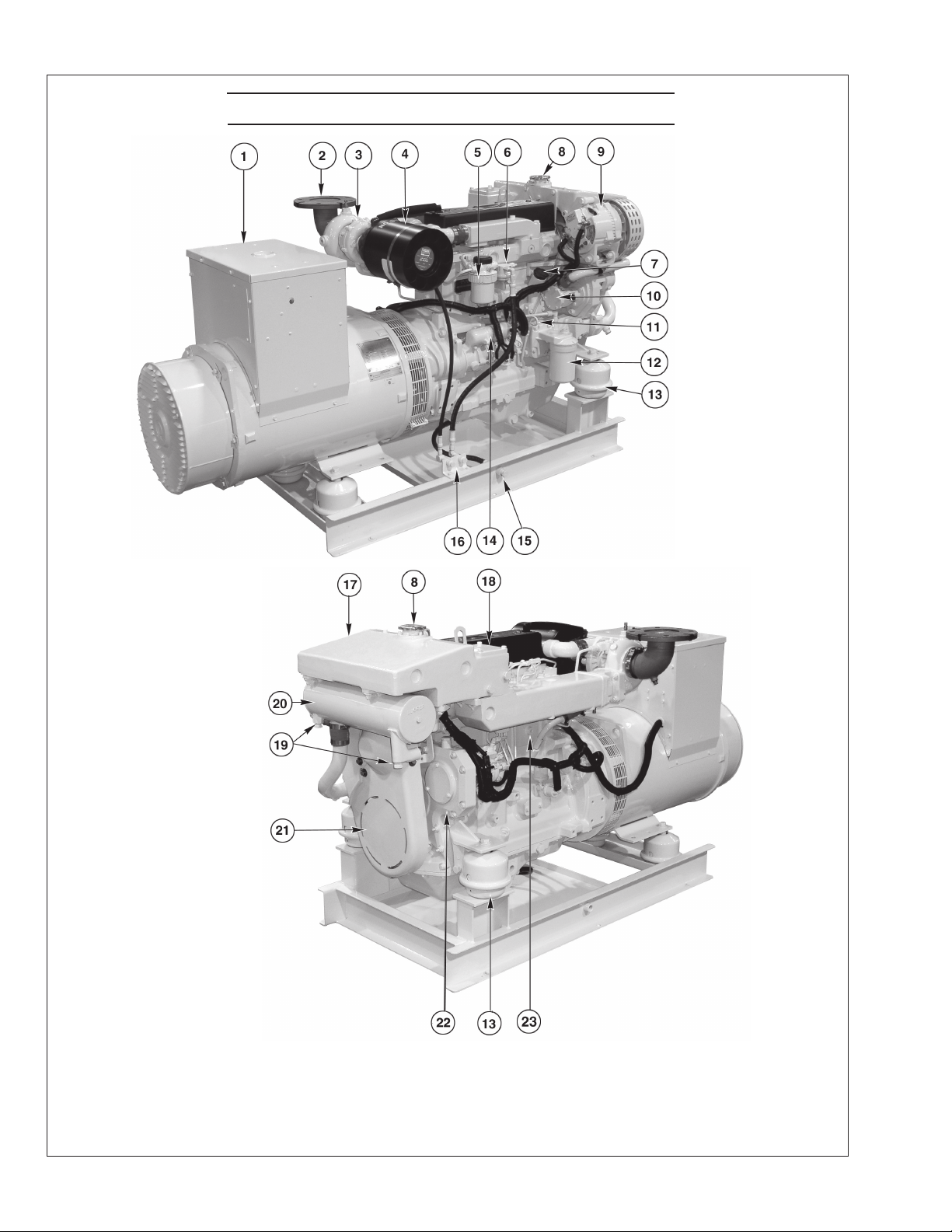
Component Locations
Figures 1 & 2: M1064T1
(Mechanically Controlled Fuel System)
1. Junction Box
2. Exhaust Elbow
3. Turbocharger
4. Air Cleaner
5. Fuel Filter
6. Fuel Lift Pump
7. Lube Oil Fill
8. Coolant Fill
9. Alternator
10. Raw Water Pump
11. Lube Oil Dipstick
12. Lube Oil Filter
13. Optional Hydrolastic Mount
14. Starter
15. Lube Oil Drain
16. Fuel Manifold
17. Expansion Tank
18. Thermostat Cover
19. Heat Exchanger Zincs
20. Heat Exchanger
21. Belt Guard
OM2-2 1/17
10
22. Injection Pump Drive
Coupling Access Cover
Plate
23. Engine Block Drain
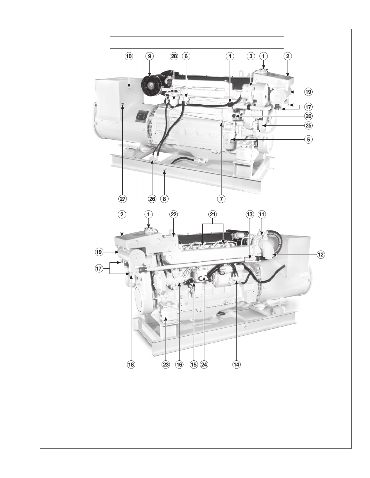
Component Locations
Figure 3 & 4: M1066T (Mechanically Controlled Fuel System)
1. Coolant Fill
2. Expansion Tank
3. DC Alternator
4. Lube Oil Fill
5. Lube Oil Filter
6. Fuel Lift Pump
7. Lube Oil Dipstick
8. Lube Oil Drain
9. Air Cleaner
10. DC Circuit Breaker
11. Turbocharger
12. Wet Exhaust Elbow
13. Exhaust Manifold Drain
14. Electric Starter
15. Engine Block Drain
16. Fuel Injection Pump
OM2-2 1/17
17. Heat Exchanger Zinc (2)
18. Heat Exchanger Drain
19. Heat Exchanger
20. Raw Water Pump
21. Fuel Injectors (6)
22. Thermostat cover
23. Optional Hydrolastic
Mounts
11
24. Optional Governor Actuator
25. Drive Belt Cover
26. Fuel Manifold
27. A.V.R. Fuse
28. Fuel Filter
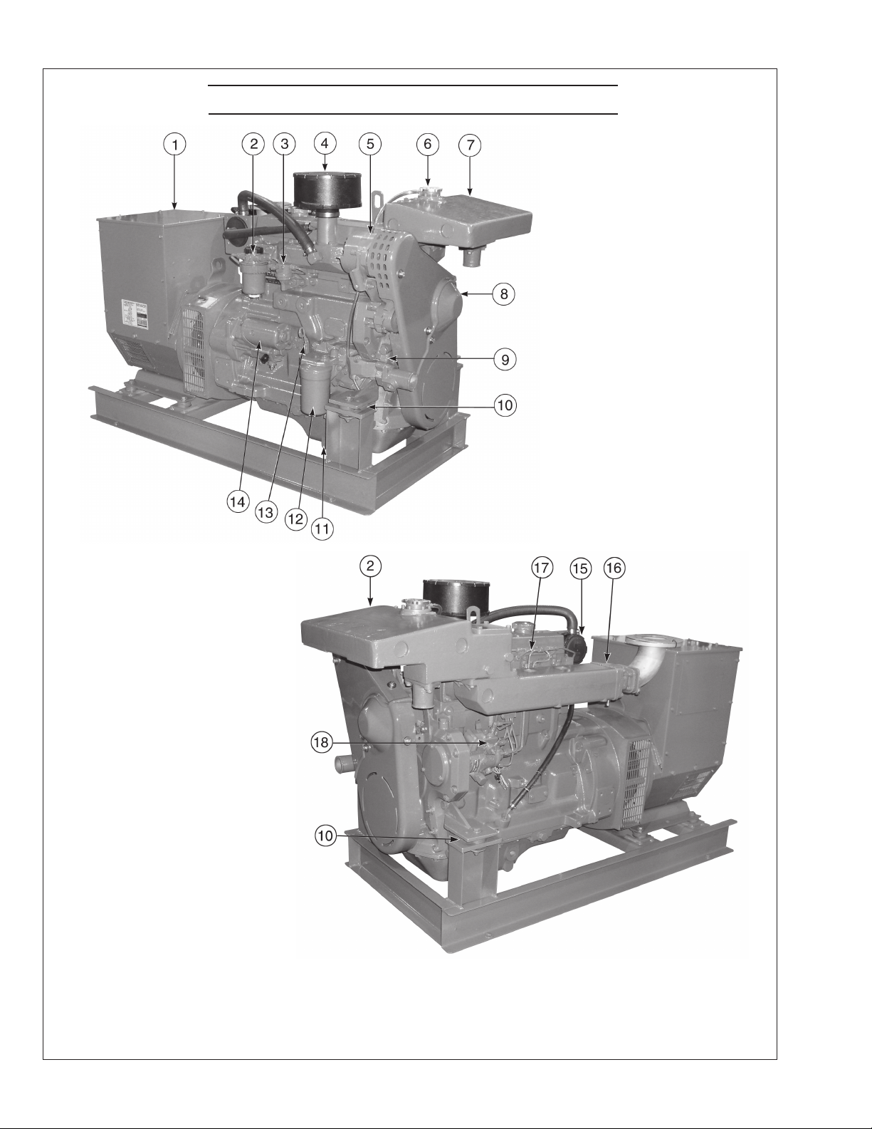
Component Locations
Figure 5 & 6: M40C2 (Mechanically Controlled Fuel System)
1. Junction Box
2. Fuel Filter
3. Fuel Lift Pump
4. Air Cleaner
5. Alternator
6. Coolant Fill
7. Expansion Tank
8. Belt Guard
9. Coolant Pump
10. Centerbonded Mounts
11. Lube Oil Drain
12. Lube Oil Filter
13. Dipstick
14. Electric Starter
15. Closed Crankcase Vent
OM2-2 1/17
16. Exhaust Manifold
17. Injection Lines
18. Fuel Injection Pump
12
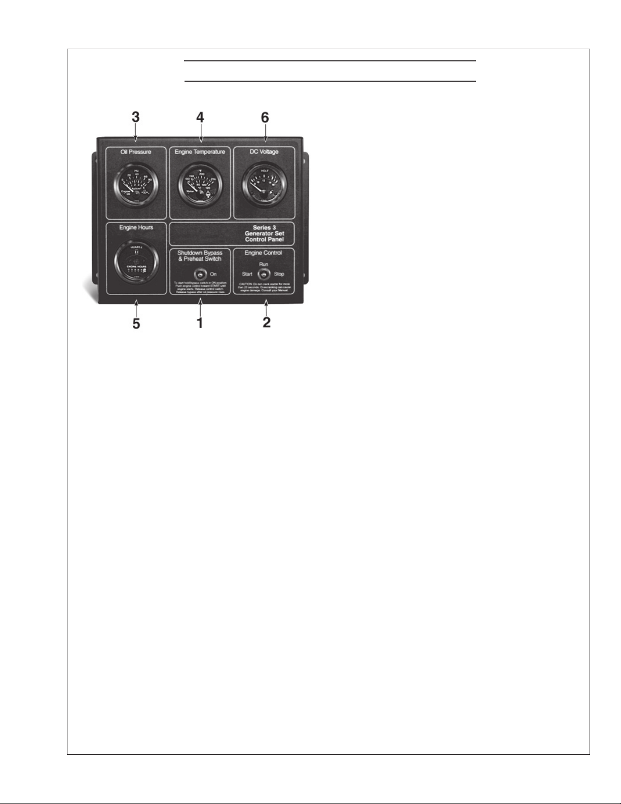
Northern Lights Control Panels
Figure 7: Series 3B Generator Control Panel
1. SHUTDOWN BYPASS SWITCH
This switch bypasses the safety shutdown feature
during the starting process.
2. ENGINE CONTROL SWITCH
To start the engine, hold this switch in the START
position until the engine is running.
NOTE: Excessive cranking of marine sets equipped
with water lift muer systems can cause engine
damage.
After the engine starts, release the switch and it will
return to RUN position. To stop the engine, hold
the switch in the STOP position.
3. OIL PRESSURE GAUGE
The oil pressure gauge shows the oil pressure in
the engine lubricating system. If the pressure drops
below 15 PSI at a speed higher than idling, stop the
engine and investigate.
4. COOLANT TEMPERATURE GAUGE
Water temperature gauge shows the temperature of
the cooling water. If the gauge registers over 200°F
(93.30C) or drops below 140°F (600C), stop the
engine and investigate.
5. HOUR METER
Keeps track of the engine running time.
6. DC VOLTMETER
When the engine is running, it indicates the
voltage output of the alternator.
OM2-2 1/17
13
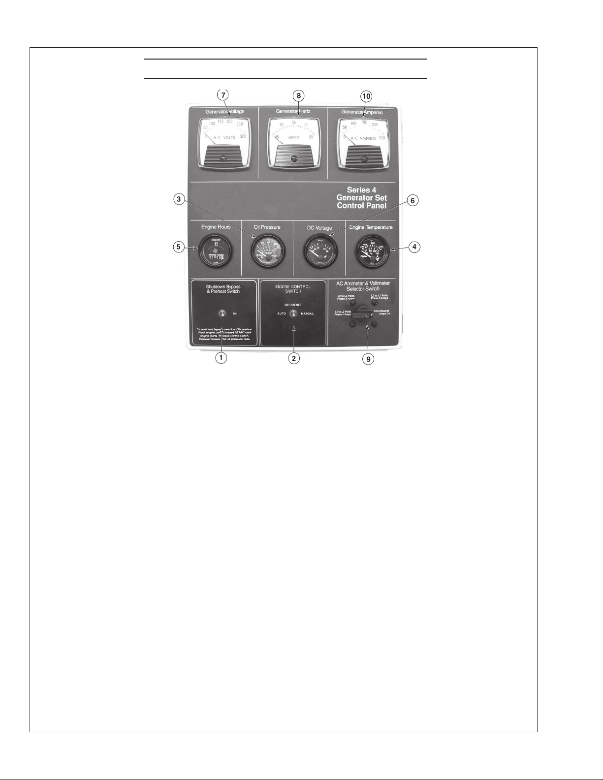
Northern Lights Control Panel
Figure 8: Series 4 B Generator Control Panel
1. SHUTDOWN BYPASS SWITCH
This switch bypasses the safety shutdown feature
during the starting process.
2. ENGINE CONTROL SWITCH
The control switch starts and stops the engine.
3. OIL PRESSURE GAUGE
The oil pressure gauge shows the oil pressure in
the engine lubricating system. If the pressure drops
below 15 PSI at a speed higher than idling, stop the
engine and investigate.
4. COOLANT TEMPERATURE GAUGE
Water temperature gauge shows the temperature of
the cooling water. If the gauge registers over 200°
(93.30C) or drops below 140°(600C), stop the engine
and investigate.
5. HOUR METER
Keeps track of the engine running time.
6. DC VOLTMETER
When the engine is running, it indicates the voltage
output of the alternator.
7. AC VOLTMETER
The voltmeter shows the generator output
voltage, phase to phase. If the voltage
uctuates greatly from the normal reading, shut
down the unit and investigate.
8. FREQUENCY METER
Indicates engine speed. The correct reading for
1800 and 1200 RPM sets is 60 Hz. For 1500 RPM
sets, it is 50 Hz. If meter does not indicate correct
hertz, stop and investigate.
9. AMMETER SELECTOR SWITCH
The ammeter switch is used for checking each
phase for load condition. Leave it in the ON
position while the engine is running.
10. AC AMMETER
The ammeter indicates the phase load. Check for
load unbalance. If the unbalance is greater than
30%, have an electrician balance the load properly.
This will ensure longer generator life and better
economy.
OM2-2 1/17
14
revised 3-19-13
Emission-Related Installation & Instructions
Failing to follow these instructions when installing
a certied engine in a vessel violates federal law (40
CFR 1068.105(b)), subject to nes or other penalties as
described in the Clean Air Act.
The installed exhaust system should not create exhaust
back pressure greater than 30” (760 mm) of water for
Operating Procedures
BEFORE STARTING
1. Check the water level by removing the pressure
cap from the expansion tank. In order to give the
cooling water room to expand, the level should be
about 1 3/4 in. (4-5 cm) below the ller cap sealing
surface when the engine is cold. When lling with
coolant, the venting cock on top of the turbocharger
should be opened to ensure that no air pockets form
in the cooling system (see Service Point #14).
CAUTION: Use protective clothing and open
the ller cap carefully when the engine is warm
to prevent burns.
2. Check the oil level in the crankcase with the dipstick.
The oil level should be between the “waed area”
and the “oo”. Never allow the level to go below
the “oo”. Always add the same viscosity of oil as is
already in the crankcase (see Service Point #1).
3. Check the fuel tank level and open any fuel valves.
4. Disengage clutch, if equipped.
5. Close the seacock, check and clean the strainer and
reopen the seacock.
6. Place the battery switch in the ON position.
NOTE: The battery switch must always be kept
ON while the engine is running. If the switch is
turned OFF while the engine is running, the battery
charging regulator could be ruined.
Starting
1. While holding the Shutdown Bypass switch in the
ON position, push the Engine Control switch to the
START position.
2. As soon as the engine starts, release both switches.
Do not crank the starter for more than 20 seconds.
3. If the engine fails to start the rst time, be sure the
starter has stopped before re-engaging.
a turbocharged engine and 48” (1200 mm) for a non-
turbocharged unit, measured at the engine exhaust elbow.
If you install the engine in a way that makes the engine’s
emission control information label hard to read during
normal engine maintenance, you must place a duplicate
label on the vessel, as described in 40 CFR 1068.105.
NOTE: If there is a governor locked at a specic
speed on the generator set, there may not be a slow
idle function, so in that case operate the engine at
high idle for 1 to 2 minutes before adding load. If
the stand-by generator set is loaded as soon as
it reaches rated speed, this procedure would not
apply.
Operating
1. Check Gauges Often: Oil pressure must be above
29 PSI (if not above 15 PSI within 5 seconds of
starting, the engine should be stopped and the
problem should be explored). Normal oil pressure
is 50 PSI at rated load speed (1800 to 2500 RPM).
Oil temperature should be 1150C (2400F) for normal
operating temperature. The D.C. voltmeter should
read between 13 and 14 volts (26-28 volts, 24 volt
systems).
2. Check AC voltage and frequency meters (Series 4
Panel). If gauges deviate from normal levels, shut
down the set and investigate.
3. Check belt for good alignment.
4. Let the unit run unloaded for a three to ve minute
warm-up period before applying load.
5. Do not add full electrical load until engine is at
maximum operating temperature.
Shutdown
1. Turn the Engine Control Switch to the OFF
position.
2. Close the sea cock and fuel valves, and put the
battery switch in the OFF position if the unit will be
o for an extended period.
NOTE: Do not turn the battery switch to OFF while
the engine is running.
OM2-2 1/17
15
revised 3-19-13
Operating Procedures
SHUTDOWNS AND ALARMS
1. Your unit is tted with a system to protect it from
high water temperature or low oil pressure.
a. Generator sets have shutdown systems to stop
the engine. They have no warning horns.
b. Other alarms and shutdowns are available as
optional equipment.
NOTE: Do not rely on your warning or shutdown
system to the exclusion of careful gauge monitoring.
Watching your gauges can prevent damage to the unit
and dangerous power losses.
2. Do the following when your shutdown system is
activated:
a. Check the temperature gauge. If the temperature
is above 205°F (97°C), shut o the engine
immediately.
b. Use the Trouble Shooting Guide on pages 26- 28
to isolate the cause of the overheat.
CAUTION: Do not remove the water ll cap of
an overheated engine. Escaping high
temperature steam can cause severe burns.
Allow the engine to cool and then remove the
cap slowly, using protective clothing.
c. Make repairs and restart after the temperature
gauge registers below 180°F (83°C).
d. Watch the temperature gauge regularly and
turn o the unit if the temperature rises above
200°F (93.3°C). Repeat the troubleshooting
process.
BREAK-IN PERIOD
1. Your engine is ready to be put into service.
However, the rst 100 hours on a new or
reconditioned engine are critical to its life and
performance. This is especially true of an engine
that runs at a constant speed such as a generator
engine.
2. Operate the engine under various conditions,
particularly heavy loads with minimal idling, to
help seat engine components properly.
3. Oil consumption is greater during break-in as piston
rings take time to seat.
4. Your engine comes equipped with break-in oil.
Change engine oil and lter at 50 hours using API
Service Category CC, CD, or CE break-in oil.
Change the oil and lter again at 100 hours.
(Consult the lubricants section for oil
recommendation.)
5. Frequently check the engine temperature and oil
pressure gauges.
3. If the shutdown is activated and the temperature
gauge shows temperature within normal temperature
range:
a. Check the engine crankcase oil level.
b.
If the oil level is low, ll with recommended
lubricating oil and restart. Watch the oil pressure
gauge carefully and shut o the engine if it does
not show a normal reading after a few seconds of
operation.
c. If the oil level was normal, DO NOT restart the
engine. Call your Northern Lights or Lugger
dealer for assistance.
OM2-2 1/17
16
 Loading...