

Northern Lights L6170A, M6170A Operator's Manual
OPERATOR’S
OPERATOR’S
MANUAL
MANUAL
L6170A and M6170A
O6170
For Models

— CALIFORNIA —
Proposition 65 Warning:
Diesel engine exhaust and some of its constituents
are known to the State of California to cause
cancer, birth defects, and other reproductive harm.
Northern Lights
4420 14th Avenue N.W.
P.O. Box 70543
Seattle, WA 98107
Tel: (206) 789-3880
Fax: (206) 782-5455
Copyright ©2003 Alaska Diesel Electric, Inc.
All rights reserved. Northern Lights™, and
the Northern Lights logo are trademarks of
Alaska Diesel Electric, Inc.
Printed in U.S.A.
PART NO.: O6170 03/03

O6170
OPERATOR'S MANUAL FOR MODEL 6170
Read this operator's manual thoroughly before starting to operate your equipment.
This manual contains information you will need to run and service your new unit.
TABLE OF CONTENTS
Introduction ......................................................... 2
Unit Identification
Model Designation........................................ 2
Serial Numbers .............................................. 2
Warranty ............................................................... 3
Safety Rules ......................................................... 3
Component Locations
Lugger Propulsion Unit ............................... 4
Marine Generator Set.................................... 5
Panels
Instrument Panels ......................................... 6
Series 3 & 4 Control Panels .......................... 7
Operating Procedures
Before Starting ............................................... 8
Shutdown Procedures .................................. 9
Break-in Period .............................................. 9
Servicing Schedule Chart................................ 10
Service Record................................................... 11
Servicing
Lubrication - General.................................. 12
Oil Changes.................................................. 12
Changing Oil Filter ..............................12 - 13
Air Filter ....................................................... 13
V-Belts........................................................... 13
Valve Clearances ......................................... 13
Fuels - General ............................................. 14
Fuel Filters.................................................... 14
Bleeding the Fuel System ........................... 14
Injectors.................................................. 14 - 15
Injection Pump...................................... 15 - 17
Servicing (cont.)
Turbocharger ............................................... 17
Cooling System Requirements ...........18 - 20
Checking Coolant Level ............................. 20
Flushing the Cooling System.............. 20 - 21
Heat Exchanger Cleaning .......................... 21
Cleaning Gear Oil Coolers ......................... 21
Zinc Electrodes ............................................ 21
Raw Water Pump ........................................ 21
Coolant Filter ............................................... 21
Electrical System - General ........................ 22
Booster Batteries .......................................... 22
Battery Care ................................................. 22
Winterizing - Out-of-Service ..................... 22
Propeller Sizing Chart ..................................... 23
Data Sheets
Lugger Propulsion ...................................... 24
Northern Lights Marine Generator Set .... 25
Troubleshooting
Electrical ....................................................... 26
Engine ........................................................... 27
DC Wiring Diagrams
24 Volt Lugger Engine................................ 28
24 Volt Marine Generator Set .................... 29
24 Volt Industrial Generator Set ............... 30
Onboard Spare Parts ........................................ 31
Proprietary Information
in whole or part without the written permission of Alaska Diesel Electric, Inc. ©Alaska Diesel Electric, Inc.
This publication is the property of Alaska Diesel Electric, Inc. It may not be reproduced
All rights reserved. Litho USA. Publication number O6170 03/03
O6170 03/03
3
INTRODUCTION
Servicing of marine engines and generator sets
presents unique problems. In many cases
boats cannot be moved to a repair facility.
Marine engines cannot be compared to the
servicing of automobiles, trucks or even farm
equipment. Failures often occur in remote
areas far from competent assistance. Marine
engines are taxed far more severely than auto
or truck engines; therefore, maintenance
schedules must be adhered to more strictly.
Failures usually begin with minor problems
that become amplified when not corrected
during routine maintenance.
As owner-operator, it is your obligation to
learn about your equipment and its proper
maintenance. This manual is not a
comprehensive technical service manual. Nor
will it make the reader into an expert
mechanic. Its aim is to aid you in maintaining
and servicing your equipment properly.
UNIT IDENTIFICATION
MODEL NUMBER
Model numbers give unit's application, block model, aspiration and RPM:
L - M - NL 6170 A
L - Lugger marine propulsion engine Model number of A - Aftercooled (turbo)
M - Northern Lights marine generator set Komatsu engine block
NL - Northern Lights industrial generator set 6 cylinder, 170 mm bore
Examples:
L6170A
M6170A
Lugger turbocharged-aftercooled marine propulsion
engine. Komatsu 6170 block.
Northern Lights turbocharged 1800 or 1500 RPM
marine diesel generator set. Komatsu 6170 block.
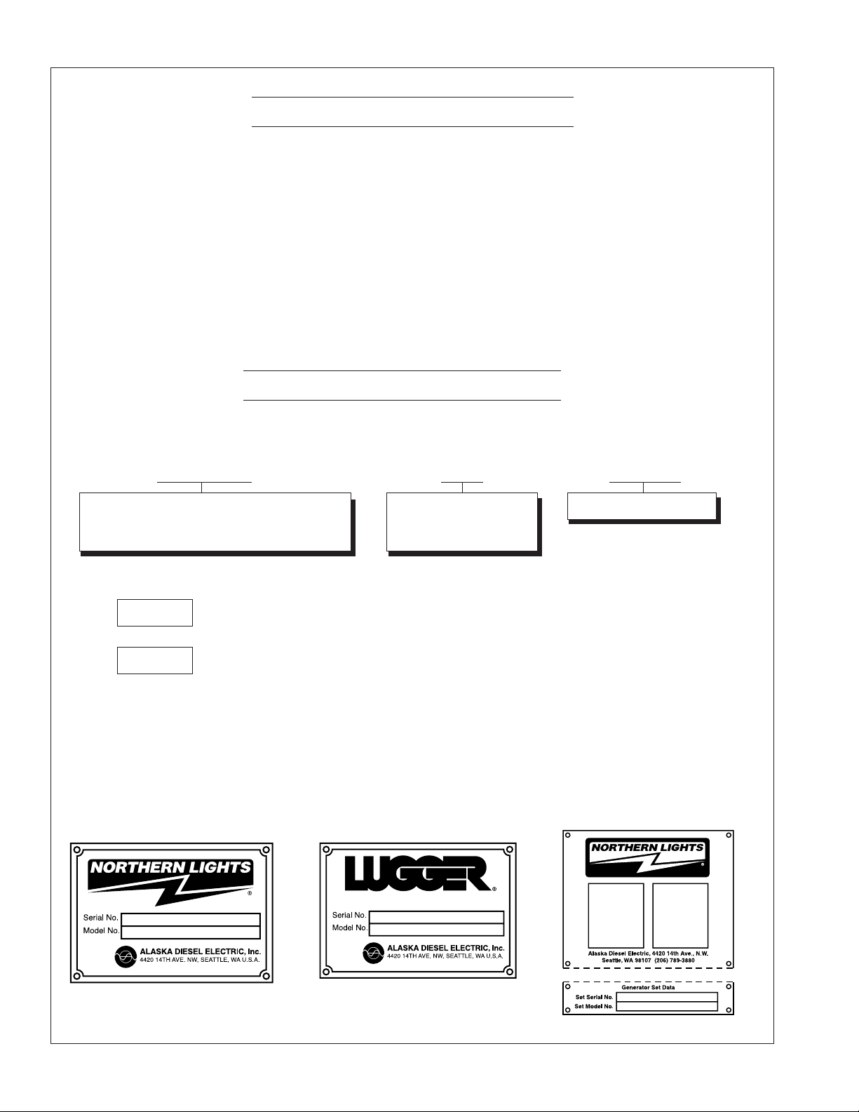
SERIAL NUMBERS
When referencing Alaska Diesel Electric equipment by serial number, refer only to the number
stamped on the Lugger or Northern Lights serial number plate.
O6170 03/03
4
WARRANTY
A warranty registration certificate is supplied
with your set. It entitles the original purchaser
of this equipment to a warranty covering
material or assembly faults. The extent of
coverage is described in the Limited Warranty
Statement. We recommend that you study the
statement carefully.
SAFETY RULES
Accident reports show that careless use
of engines cause a high percentage of
accidents. You can avoid accidents by
observing these safety rules. Study these rules
carefully and enforce them on the job.
• Never leave engine without proper security.
• Turn the coolant tank cap slowly to relieve
pressure before removing. Add coolant only
when the engine is idling or stopped.
• Mount fire extinguisher near engine.
• Always disconnect the battery ground strap
before making adjustments.
• Operate engines in properly ventilated
areas.
• Keep trash and other objects away from
engine.
• Escaping fluids under pressure can
penetrate your skin. Use a piece of cardboard
or wood, not your hands, to search for leaks.
If the warranty is to apply, the servicing
instructions outlined in this manual must be
followed. If further information is needed,
please contact an authorized dealer or the
factory.
• Avoid wearing loose clothing without a belt
when working around engines.
• Do not oil or grease engine while it is running.
• Use caution in handling fuel. Never refuel a
hot or running engine. Do not smoke while
filling fuel tank or servicing fuel system.
• Keep your hands, feet, hair and clothing away
from power-driven parts.
• Check for any loose electrical connections or
faulty wiring.
• Engines should be operated only by
knowledgeable, qualified personnel.
• Walk completely around engine to make sure
that everything is clear before starting the
engine.
• Do not operate an engine that isn't in proper
working order. If an unsafe operating condition
is noted, tag the engine so others will also know
about it.
• Provide first aid kits.
O6170 03/03
5

COMPONENT LOCATIONS
Lugger Propulsion L6170A
Figure 1. L6170A
1. Expansion Tank
2. Zinc (2)
3. Fuel System Bleed Plug
4. Fuel Filters (2)
5. Crankcase Vent Outlet
7. Lube Oil Change Pump (opt.)
8. Pump Valve
9. Oil Filters (2)
10. Oil Fill
11. Lube oil dipstick
12. Fuel Priming Pump (Manual)
13. Injection Pump
14. Crankshaft Pulley (Front
PTO optional)
O6170 03/03
15. Raw Water Pump
16. Airsep Air Filter (opt.)
Foam Air Filter Standard
17. Coolant Filter
18. Cooling System Vent
(K.C. only)
19. Coolant Filler Cap
6
20. Heat Exchanger
21. Jacket Water Pump
22. Gear Oil Cooler & Heat
Exchanger Jacket water drain
23. Gear Oil Cooler
24. Jacket water block drain
25. Starters (2)
26. Turbocharger
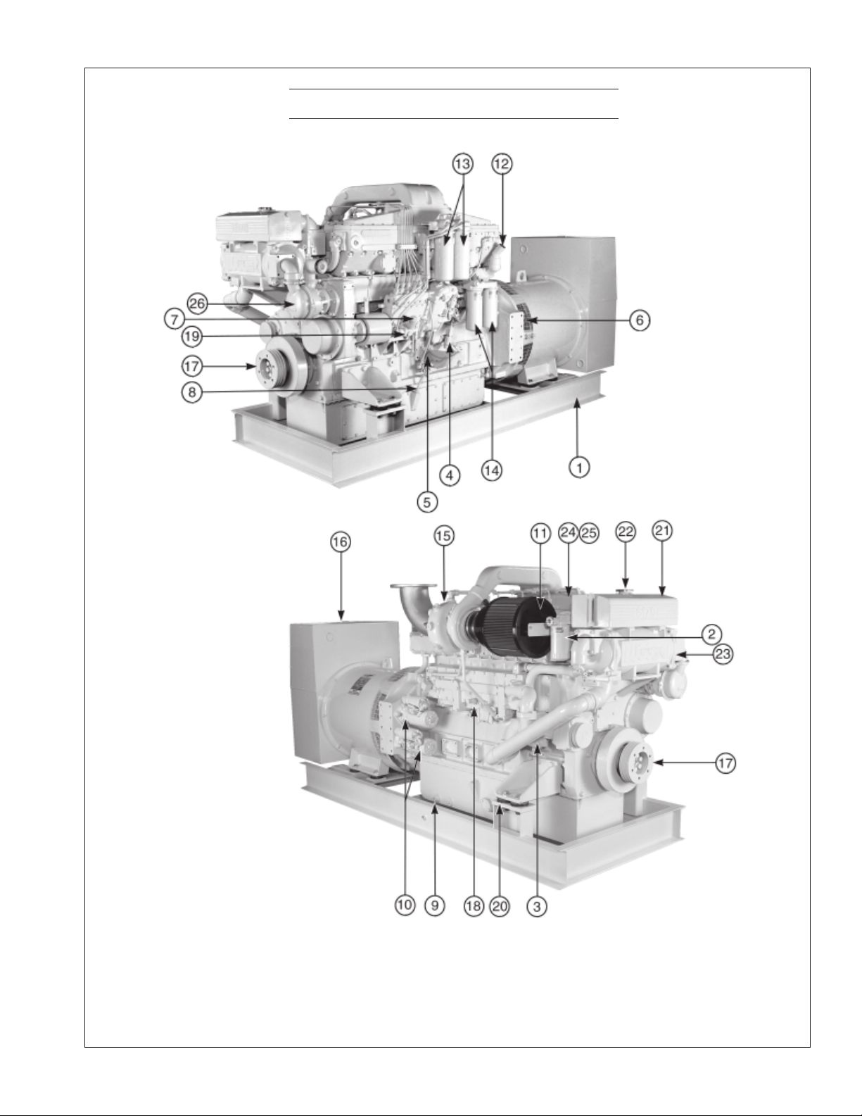
COMPONENT LOCATIONS
M6170A Northern Lights Marine Generator Set
Figure 2. M6170A Generator Set
1. Base Frame
2. Coolant Filter
3. Fresh Water Pump
4. Stop Solenoid
5. Lube Oil Fill
6. Generator Fan
7. Fuel Feed Pump and
Manual Priming Pump
8. Lube Oil Dipstick
9. Lube Oil Drain
10. Starter (2)
11. Air Cleaner
12. Crankcase Vent
13. Secondary Fuel Filter
14. Lube oil filter
15. Turbocharger
16. Generator "J" box
17. Crankshaft Pulley
18. Block drain
19. Fuel injection pump
O6170 03/03
7
20. Anti-vibration mounts
21. Expansion tank
22. Coolant system fill
23. Heat exchanger
24. Rocker arm cover
25. Cylinder head
26. Raw water pump
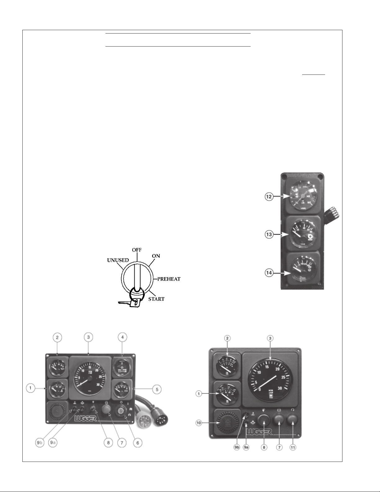
INSTRUMENT PANEL
1. OIL PRESSURE GAUGE:
The oil pressure gauge shows the oil pressure in
the engine lubricating system. If the oil pressure drops BELOW 15 PSI at a speed higher
than idling, stop engine immediately and
investigate.
2. WATER TEMPERATURE GAUGE:
This gauge shows the temperature of the
cooling water. If a temperature of over 205
indicated, stop engine and investigate immediately.
3. TACHOMETER:
The tachometer shows the engine speed in
revolutions per minute (RPM). Numbers are
multiples of 100.
4. VOLTMETER:
When the engine is stopped, the voltmeter
will indicate the condition of the battery.
When the engine is running, it shows the
alternator voltage output.
5. HOUR METER:
The hour meter keeps
track of the accumulated length of the
engine's operating
time.
6. KEY SWITCH:
The key must be kept
in "ON" position while the engine is running.
7. STOP BUTTON:
Hold down until engine is completely stopped.
8. INSTRUMENT LIGHTING DIMMER :
Adjust instrument panel lights. (On some panels
this is an on/off switch and not a dimmer.)
9. WARNING LIGHTS:
o
is
a. Light comes on when oil pressure is too low.
b. Light comes on when engine is too hot.
10. ALARM HORN:
Will sound in case of overheating or low oil
pressure. Stop engine and investigate. Remember
horn will sound when
key is in "ON" position
with engine stopped
because there is no oil
pressure.
11. START BUTTON:
Will start engine only
if key on main panel is
in "ON" position.
12. EXHAUST
TEMPERATURE:
Maximum temperature: 975°F (510°C).
13. TURBO BOOST
GAUGE
14. GEAR PRESSURE GAUGE:
See Gear Manual for operating range.
Figure 5 Auxilliary
Panel
Figure 3 - Main Panel
Figure 4 - Flybridge Panel
O6170 03/03
8
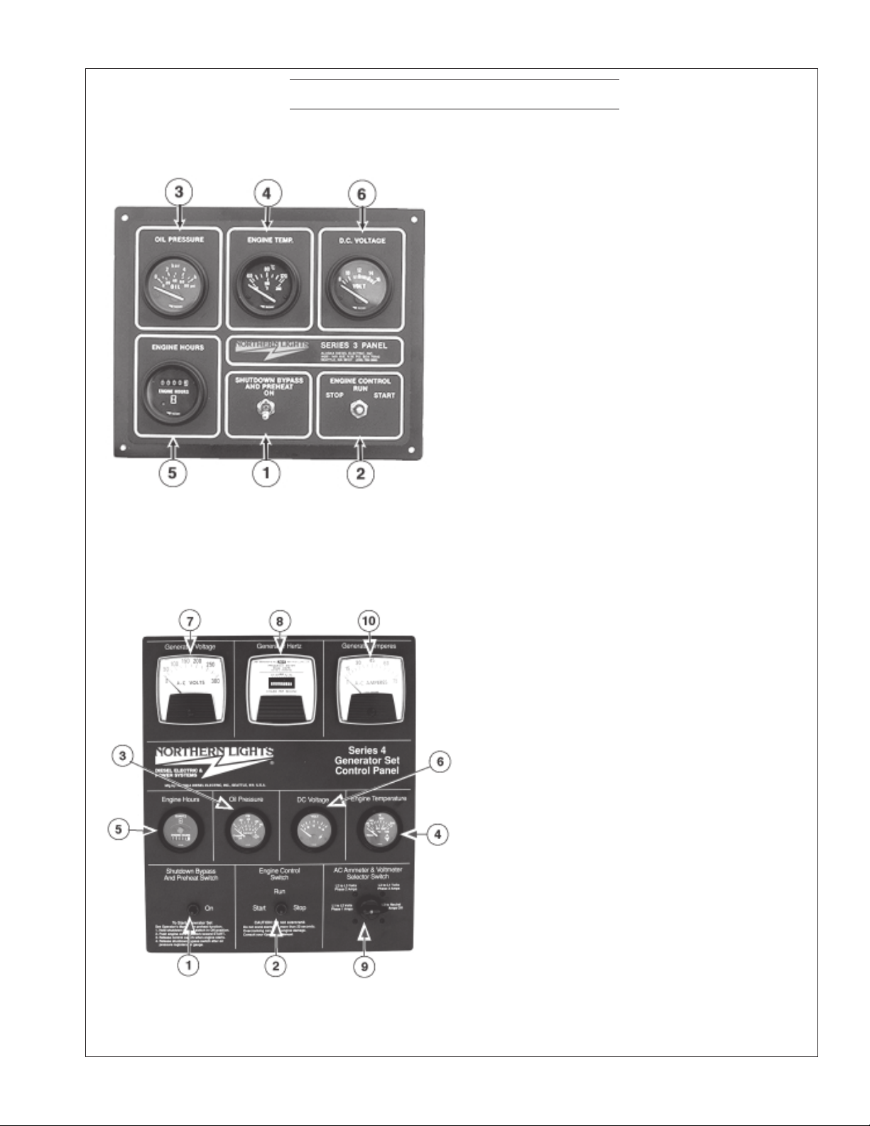
CONTROL PANELS
SERIES 3 GENERATOR CONTROL PANEL
Figure 6
1. SHUTDOWN BYPASS PREHEAT
SWITCH:
Two functions are built into this switch: The
preheating of the engine, and bypassing of the
engine safety shutdown circuit, enabling a
quicker start. Hold switch in up position 10-20
seconds before starting engine, and continue
holding in up position while starting engine.
Holding the switches on too long can burn out
the heater elements.
2. ENGINE CONTROL SWITCH:
To start the engine, hold switch in start position
until the engine is running. After the engine
starts, release switch and it will return to the
center position. To stop engine, move switch to
stop position and release.
3. OIL PRESSURE GAUGE:
The oil pressure gauge shows the oil pressure in
the engine lubricating system.
4. WATER TEMPERATURE GAUGE:
Registers temperature of cooling water.
SERIES 4 GENERATOR CONTROL PANEL
Figure 7
5. HOUR METER:
Keeps track of engine running time.
6. D.C. VOLTMETER:
When the engine is stopped, the voltmeter
indicates the condition of the battery. When the
engine is running, the voltmeter indicates the
voltage output of the alternator.
For Series 4 Control Panels Only:
7. A.C. VOLTMETER:
Shows the generator output voltage.
8. FREQUENCY METER (HERTZ):
The frequency meter indicates the frequency of
alternating current: 1200 or 1800 RPM (60
Hz), 1500 RPM (50 Hz).
9. AMMETER SELECTOR SWITCH:
Used to check each phase for load condition.
You must always leave this switch in the "ON"
position while the unit is running.
10. A.C. AMMETER
Shows the generator load on each phase. The
phase is selected on the Ammeter Selector
Switch (switch #9 above).
O6170 03/03
9
OPERATING PROCEDURES
BEFORE STARTING
1. Check the water level by removing the pressure
cap from the expansion tank. In order to give
the cooling water an opportunity to expand, the
level should be about 1 3/4 in. (4-5 cm) below
the filler cap sealing surface when the engine is
cold. When filling with coolant, all the venting
cocks should be opened to ensure that no air
pockets form in the cooling system.
CAUTION: Use protective clothing and
open the filler cap carefully when the
engine is warm to prevent burns.
2. Check the oil level in the crankcase with the
dipstick. The oil level must be in the waffled
area between the "L" and "H." Never allow the
level to go below the "L." Always add the same
viscosity of oil as is already in the crankcase.
3. Check the fuel tank level and open any fuel
valves.
4. Propulsion Only: Check the oil level in the
reverse gear. Methods may vary from gear to
gear. See your Gear Owner's Manual.
5. Close the sea cock, check and clean the strainer
and reopen the sea cock.
6. Place the battery switch in the ON position.
NOTE: The battery switch must always be kept
ON while the engine is running. If the switch
is turned OFF while the engine is running,
the battery charging regulator could be
damaged.
GENERATOR
Starting
1. While holding the Shutdown Bypass/ Pre-heat
switch in ON position, push the Engine Control
switch to START position. As soon as the
engine starts, release both switches. Do not
crank the starter for more than 20 seconds. If
the engine fails to start the first time be sure the
starter has stopped before re-engaging.
2. Cold Weather: Hold Shutdown Bypass/ Preheat switch in the ON position for 30 seconds
before starting. This will warm the air heater
elements and will ease starting. This is not
necessary if engine is warm. A longer pre-heat
time may be required in extremely cold
weather.
Operating
1. Check Gauges Often: Oil pressure must be
above 29 PSI. The DC voltmeter should read
between 13 and 14 volts (26-28 volts, 24 volt
systems) at 60
Water temperature gauge must be below 205
o
(96
C). Check AC voltage and frequency meters.
o
F (16oC) ambient temperature.
o
F
If gauges deviate from normal levels, shut down
the set and investigate.
2. Let the unit run unloaded for a three to five
minute warm-up period.
3. Do not add full electrical load until the engine has
reached normal operating temperature.
PROPULSION ENGINE
Starting
1. Put the gear control in the neutral position.
2. Move the throttle control to the full speed position
and return back to idle.
3. Turn the key switch to the first position. Check
the voltage meter to see the condition of the
batteries. For starting, the voltmeter should not
read below 12 volts (24 volts for 24 volt systems).
4. In cold weather, turn the key to the preheat
position and hold there for 20-30 seconds.
5. Turn the key to the starting position and as soon
as the engine starts, release the key. Move the
throttle up until the engine is running at approximately 1000 RPM.
6. Do not crank the starter for more than 20
seconds consecutively. If the engine fails to start
with the first attempt, be sure that the starter has
stopped completely before re-engaging.
NOTE: Never race a cold engine. Operate at 1000
RPM for a 3-5 minute warm-up period.
Operating
1. Check oil pressure as soon as the engine has
started. Oil pressure should be above 29 PSI. The
engine must never be run if the oil pressure is
below 15 PSI.
2. Check the voltmeter. It should read 13 to 14 volts
(26-28 volts, 24 volt systems) at 60
3. Water temperature should not rise over 200
o
C). If it does, shut down the engine and
(94
investigate the cause of overheating.
4. Do not exceed 800 RPM when shifting marine
gear. Repeated shifts at higher engine speeds can
damage the reverse gear.
5. Low Idle is 750 RPM. Maximum working engine
speed is: 2100 RPM for pleasure craft, 2000 RPM
for light commercial craft and 1800 RPM for
continuous duty applications.
o
F (16oC).
o
F
O6170 03/03
10

OPERATING PROCEDURES
6. If the proper propeller is used, the engine should
reach its appropriate maximum speed at full
throttle. If at full throttle the maximum speed is
exceeded, then the propeller is too small. If
maximum speed cannot be attained, then the
propeller is too large or bottom growth may be
slowing the boat. (See Prop Chart, page 23.)
7. To Establish Maximum Cruising RPM:
Establish the RPM at full throttle and subtract
200-300 RPM. This will promote engine life and
reduce fuel consumption.
SHUTDOWN PROCEDURES
1. Run for three to five minute cool down period.
a. Propulsion engines in neutral at 1000 RPM,
then return throttle to low idle.
b. Generators unloaded.
2. Push STOP button until the engine has stopped.
Turn key switch to OFF position.
3. Close the sea cock, fuel valves and put the
battery switch in OFF position.
NOTE: Do not turn battery switch to OFF while
engine is running.
SHUTDOWNS AND ALARMS
1. Your unit is fitted with a system to protect it
from high water temperature or low oil pressure.
a. Generator sets have shutdown systems to
stop the engine. They have no warning
horns.
b. Propulsion engines have warning horns to
sound and warn you of a problem. Remember: when engine is not running the horn
will sound when key is in the "ON" position
because there is no oil pressure. Propulsion
engines do not have shutdown systems.
c. Other alarms and shutdowns are available as
optional equipment.
NOTE: Do not rely on your warning or shutdown
system to the exclusion of careful gauge
monitoring. Watching your gauges can prevent
damage to the unit and dangerous power losses.
2. Do the following when your warning or shutdown system is activated.
a. Check the temperature gauge. If the tem-
perature is above 200
engine immediately.
b Use the Trouble Shooting Guide on page 26
to isolate the cause of the overheat.
o
F (94oC), shut off the
CAUTION: Do not remove the water fill
cap of an overheated engine. Escaping
high temperature steam can cause severe
burns.
c. Allow the engine to cool and then remove
the cap slowly using protective clothing.
d. Make repairs and restart after the tempera-
ture gauge registers below 180
o
F (82oC).
e. Watch the temperature gauge regularly and
turn off the unit if the temperature rises
o
above 200
F (94oC). Repeat the troubleshoot-
ing process.
3. If the warning or shutdown is activated and the
temperature gauge shows temperature within
normal temperature range:
a. Check the engine crankcase oil level.
b. If the oil level is low, fill with recommended
lubricating oil and restart. Watch the oil
pressure gauge carefully and shut off the
engine if it does not show a normal reading
after a few seconds of operation.
c. If the oil level is normal, DO NOT restart the
engine. Call your Northern Lights or Lugger
dealer for assistance.
BREAK-IN PERIOD
1. The first 100 hours on a new or reconditioned
engine are critical to its life and performance.
2. Constantly check the engine temperature and oil
pressure gauges.
3. Oil consumption is greater during break-in as
piston rings and cylinder liners take time to seat.
4. Break-In Oil Changes: Change engine oil and
filter at 50 hours. Change oil and filter again at
100 hours. (See Gear Owner's Manual for breakin oil change procedures. Consult Lubricants
Section for oil recommendation.)
Operating Instructions
1. Propulsion engines: Never run full speed for
more than 5 minutes during the first 50 hours.
Run engine at 50 to 75% of maximum working
speed for the first 20 hours with as little idling
time as possible. Extended idling can inhibit ring
seating, causing cylinder walls to glaze.
2. Generator Sets: Maintain at least a 75% load
on your set for the first 100 hours. If this is not
possible, maintain no less than a 50% load to
ensure proper seating of the piston rings. Vary
the load to help seat rings.
O6170 03/03
11
 Loading...