

Northern Lights M984K, ML984, L984, M30C, M33C Parts Manual
...
PARTS
PARTS
CATALOG
CATALOG
for Models M984K, ML984, L984, M30C,
M33C, M984W, and M33CW
P984
— CALIFORNIA —
Proposition 65 Warning:
Diesel engine exhaust and some of its constituents
are known to the State of California to cause
cancer, birth defects, and other reproductive harm.
NORTHERN LIGHTS
4420 14th Avenue N.W.
Seattle, WA 98107
Tel: (206) 789-3880
Fax: (206) 782-5455
Copyright ©2005 Alaska Diesel Electric, Inc.
All rights reserved. Alaska Diesel Electric™,
the Alaska Diesel Electric logo, Northern Lights™,
and the Northern Lights logo are all trademarks
of Alaska Diesel Electric, Inc.
Printed in U.S.A.
PART NO.: P984 09/05

PARTS CATALOG
for Models M984K, ML984, L984, M30C, M33C,
M984W, and M33CW
Please read thoroughly before attempting to use this manual:
Table of Contents .................................................................................................................................................... I
Model Designation & Serial Numbers ................................................................................................................... II
Reading a Parts Page ............................................................................................................................................. III
Table of Contents
GROUP 1 - ENGINE
Cylinder Block .............................................0 - 1
Crankshaft, Pistons & Connecting Rods ......2 - 5
Flywheel & Housing ......................................... 6
Lubrication System ......................................7 - 8
Timing Cover .................................................... 9
Camshaft & Valve Train ......................... 10 - 13
Cylinder Head & Valve Cover ................ 14 - 15
Oil Drain Kit.................................................... 16
GROUP 2 - INTAKE & EXHAUST SYSTEM
Air Intake & Intake Noise Reduction...........0 - 3
Intake Manifold ................................................. 4
Air Inlet ............................................................. 5
Exhaust Manifold .............................................. 6
Wet Exhaust Elbow ........................................... 7
Dry Exhaust Elbow ........................................... 8
GROUP 3 - COOLING
Expansion Tank & Thermostat Housing ........... 1
Heat Exchanger & Mounting ............................ 2
Heat Exchanger Assembly ................................ 3
Coolant Pump .................................................... 4
Keel Cooling Outlet .......................................... 5
Raw Water Pump & Mounting.......................... 6
Raw Water Pump Detail.................................... 7
GROUP 4 - FUEL SYSTEM
Injectors & Lines ..................................... 0 - 1
Injection Pump & Piping..............................2 - 3
Fuel Filter & Piping.................................. 4 - 5
Fuel System.................................................. 6
Coast Guard Approved Fuel System ................. 7
Fuel Feed Pump Assembly................................ 8
GROUP 5 - ELECTRICAL SYSTEM
Engine...........................................................0 - 5
Dual Station Relay Board.................................. 6
Circuit Breaker & Relay Assembly................... 7
Stop Solenoid & Mounting ............................... 8
Alternator Mounting.................................. 9 - 10
Alternator ................................................ 11 - 13
Starter .............................................................. 14
Control Panels ......................................... 15 - 23
Belt Guard ............................................... 24 - 28
GROUP 6 - GASKET SETS
Gasket Sets ........................................................ 1
GROUP 7 - GEAR AND ADAPTER SETS
Gear & Adapter ............................................0 - 3
GROUP 8 - FRAME & MOUNTING
Base Frame Assemblies .................................0 - 3
Front Engine Mounts......................................... 4
Lifting Eye......................................................... 5
GROUP 9 - ACCESSORIES
GROUP 9 - & OPTIONAL EQUIPMENT
PTO Adapter ................................................0 - 1
Electric Clutch................................................... 2
Oil Drain Kit...................................................... 3
Low Oil Level Switch ....................................... 4
Water Level Switch ........................................... 5
Pre-Alarm Switches........................................... 6
Raw Water Flow Switch ................................... 7
It may not be reproduced in whole or part without the expressed written permission of Alaska Diesel Electric, Inc.
This publication is the sole property of Alaska Diesel Electric, Inc.
© Alaska Diesel Electric, Inc. 2005. All rights reserved. Litho U.S.A. Publication number: P984 09/05.
Proprietary Information
P984 09/05
I
Model Designation
MODELS INCLUDED
This manual covers the operating instructions for
M984K, ML984, L984, M33C, M984W, and M33CW which use the 984 engine.
Model Numbers
Model numbers give the unit's application, block model, aspiration, and RPM:
M - L 984 L, C W
M - Northern Lights marine
generator set
L - Lugger propulsion engine
M984K
ML984
Northern Lights marine diesel generator set
=
with a 984 engine and a PX-332K generator.
Northern Lights marine diesel generator
=
set with a 984 engine and a PSL
generator.
Lugger propulsion engine with a 984 engine.L984
=
Model number of engine block
Bore Cylinders
98 mm 4
M33CW
Additional letters
designate a series within
a model number.
Northern Lights 33 kW commercial grade
M33C
M984W
=
marine diesel generator set.
Northern Lights marine diesel generator set with
=
a 984 engine and a PX-332K2 generator.
Northern Lights marine diesel generator set with
=
a 984 engine and a PX-332K2 generator.
Designates a new
winding in the
generator.
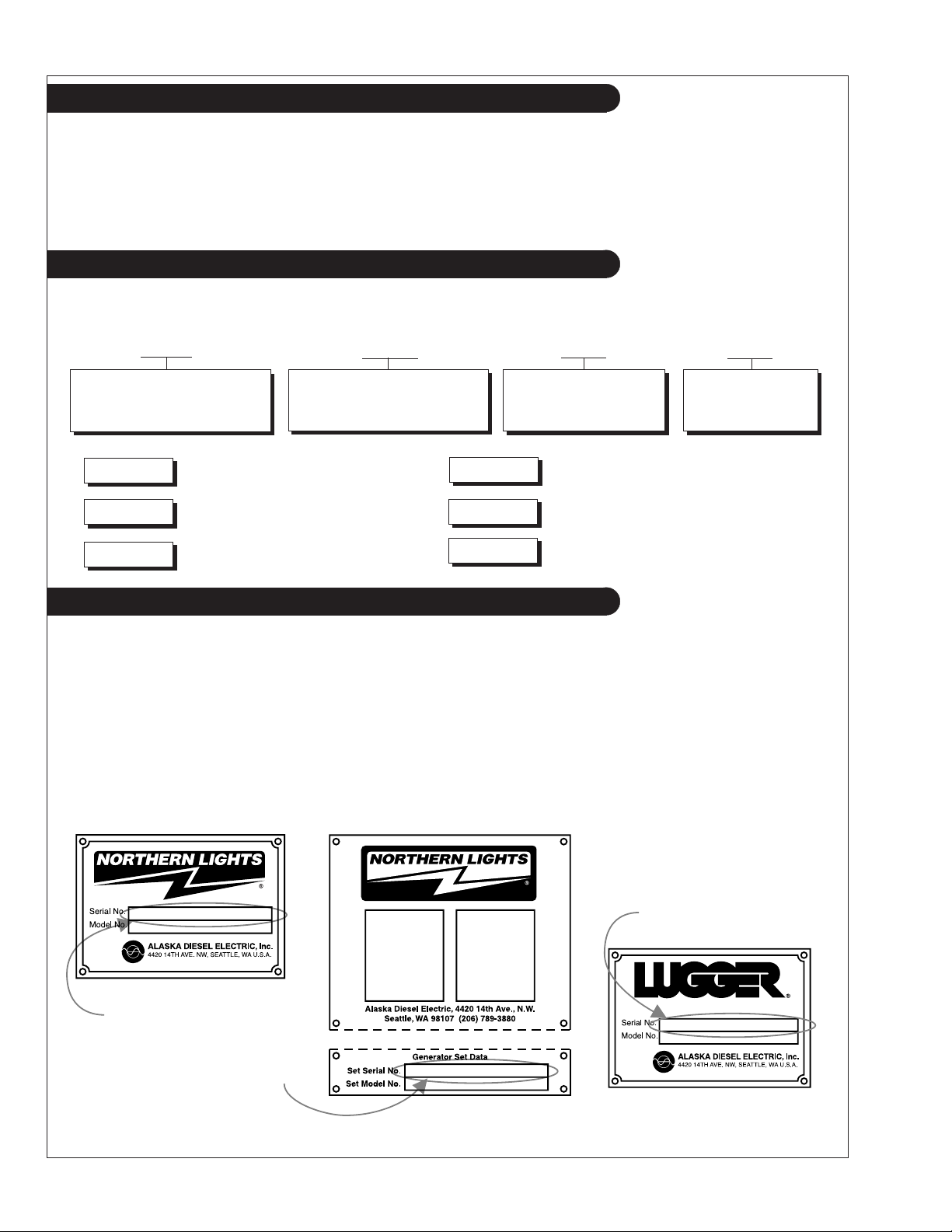
Serial Numbers
NORTHERN LIGHTS
Northern Lights generator sets with PSL generators have two data plates and two serial numbers. One serial
number is for the generator end, and it is found on the Generator End Data Plate.
found with the Generator Set Data Plate, should be used when ordering parts for sets using PSL
generators. Units with PXK generators have just one plate. Serial numbers for Northern Lights units are
eight digits in length (e.g. 1234-5678).
LUGGER
When ordering Lugger parts, please refer to the serial number located on the flywheel housing.
The other serial number,
Generator Set Serial Number
for units with PX K and PSL
generators
Generator End Serial Number
for units with PSL generators
Lugger Serial Number
P984 09/05
II
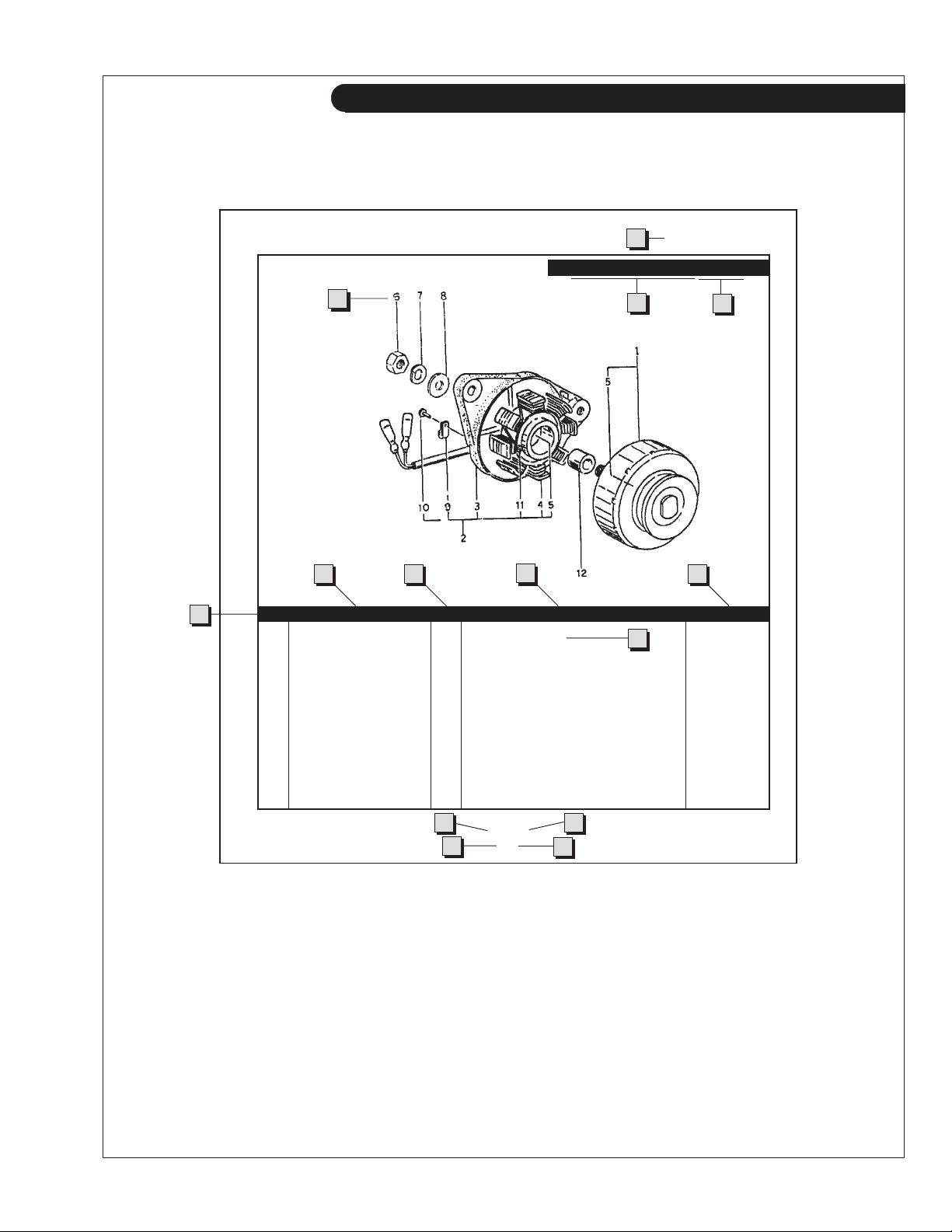
Reading a Parts Page
IMPORTANT:
Before selecting parts, be sure that you are choosing parts from the correct page.
Check the model designation at the page top.
Do not use this illustration for parts purchasing.
1
ELECTRICAL SYSTEM
ALTERNATOR ASSEMBLY: M - NL844
4
6
5
KEY PART NUMBER QTY. DESCRIPTION SERIALNUMBER
0 185046210 1 Alternator Assembly 1 185446219 1 Flywheel, complete 2 185446217 1 Plate, complete 3 185716200 1 Plate 4 185446218 1 Stator, complete 5 040126210 2 Bearing 6 020210010 1 Nut 7 027100010 1 Spring washer 8 026100010 1 Washer 9 185446220 1 Clamp 10 015140408 1 Screw 11 015140425 2 Screw 12 199236510 1 Collar -
7
8 9
10
3
2
13
11
P844 06/96
5-2
14
12
REFERENCES:
1. Grouping section title. 7. Quantity of parts used.
2. Model designation of equipment that uses parts 8. Description of each component part.
listed on this page. 9. Serial number of unit the part fits.
3. Title and description of assembly. 10. Assembly or kit designated by Key 0 or ••/•.
4. Drawing numbers that correspond to key 11. Grouping index number.
column numbers for parts identification. 12. Page number within the grouping index.
5. Key column for locating parts shown on drawing. 13. Manual title.
6. Part number. 14. Page publication date.
NOTE: ➡ Arrows always point toward the front of the engine.
P984 09/05
III
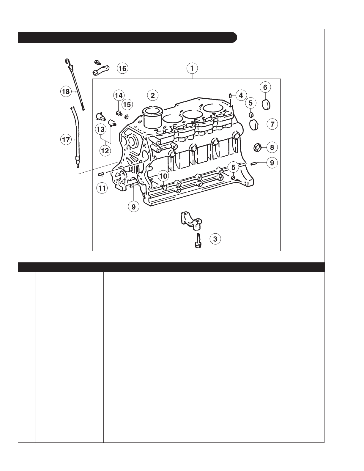
GROUP 1 – ENGINE
Cylinder Block
P984 01-00: 1105
KEY PART NUMBER QTY DESCRIPTION ENGINE BLOCK S/N
1 11401-78700-71 1 Cylinder Block Assembly up to S/N - 0042812
2 11461-78700-71 4 Cylinder Liner (Dry Type) (Mark A) -
11461-78701-71 4 Cylinder Liner
11475-78300-71 ** Liner Shim T = 0.05"
11476-78300-71 ** Liner Shim T = 0.10"
(Dry Type) (Mark B) -
(not shown) -
(not shown) -
3 90105-14950-71 10 Bolt 4 90253-15950-71 2 Pin 5 90360-14950-71 2 Expansion Plug 6 96411-45000 2 Expansion Plug 7 90331-55950-71 1 Plug 8 96411-43500 7 Expansion Plug -
9 90250-08120 6 Pin 10 90345-51003 1 Plug 11 90250-06068 2 Pin 12 96431-53828 1 Drain Cock
(includes Key #13) -
13 96432-23814 1 Drain Cock Plug 14 90341-10002 1 Plug 15 90430-10027 1 Gasket 16 11459-78301-71 1 Dipstick Tube Support 17 11452-78301-71 1 Dipstick Tube 18 15301-78700-71 1 Dipstick -
**As required.
P984 09/05
1 - 0
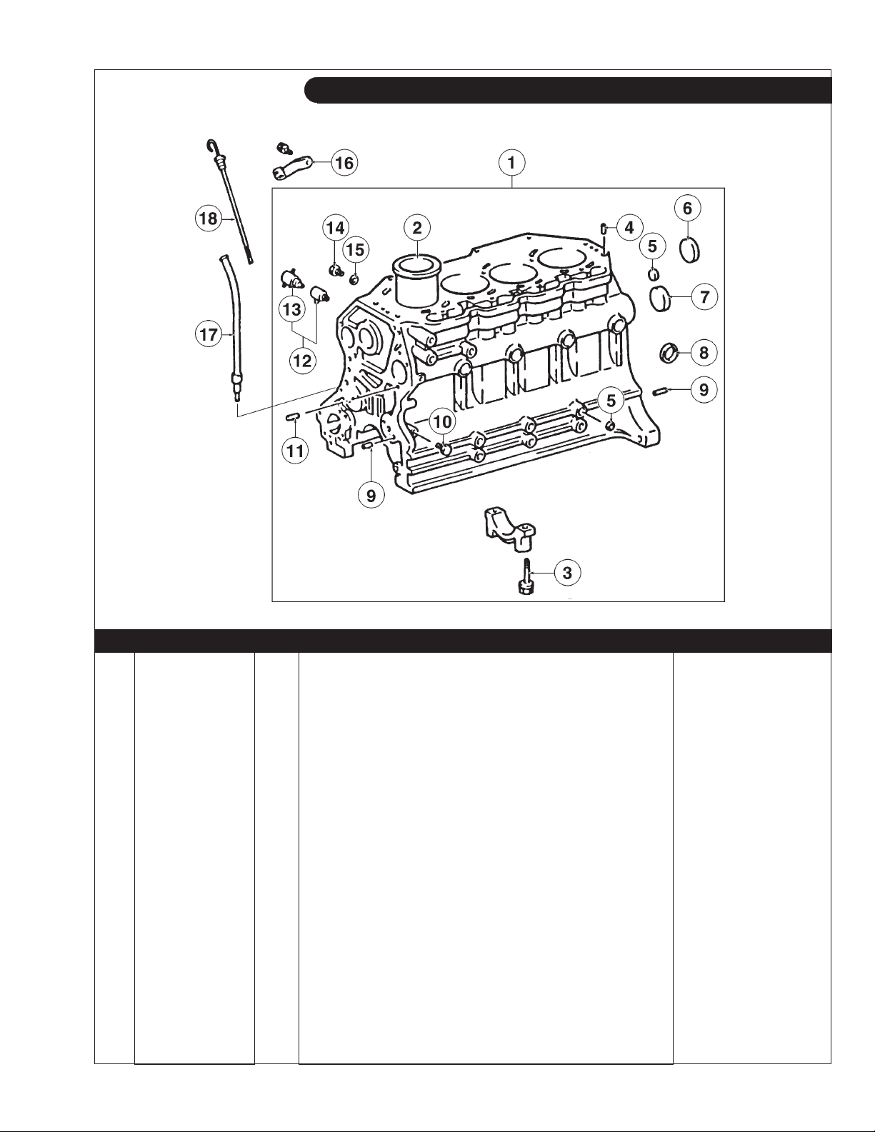
GROUP 1 – ENGINE
Cylinder Block
P984 01-00: 1105
KEY PART NUMBER QTY DESCRIPTION ENGINE BLOCK S/N
1 11401-78702-71 1 Cylinder Block Assembly
standard Crankshaft Bearings)
(includes Pressure Relief Valve & from S/N 0042813 -
2 11461-78700-71 4 Cylinder Liner (Dry Type) (Mark A) -
11461-78701-71 4 Cylinder Liner
11475-78300-71 ** Liner Shim T = 0.05"
11476-78300-71 ** Liner Shim T = 0.10"
(Dry Type) (Mark B) -
(not shown) -
(not shown) -
3 90105-14950-71 10 Bolt 4 90253-15950-71 2 Pin 5 90360-14950-71 2 Expansion Plug 6 96411-45000 2 Expansion Plug 7 90331-55950-71 1 Plug 8 96411-43500 7 Expansion Plug -
9 90250-08120 6 Pin 10 90345-51003 1 Plug 11 90250-06068 2 Pin 12 96431-53828 1 Drain Cock
(includes key #13) -
13 96432-23814 1 Drain Cock Plug 14 90341-10002 1 Plug 15 90430-10027 1 Gasket 16 11459-78301-71 1 Dipstick Tube Support 17 11452-78301-71 1 Dipstick Tube 18 15301-78700-71 1 Dipstick -
**As required
P984 09/05
1 - 1
GROUP 1 – ENGINE
Crankshaft, Pistons & Connecting Rods
P984 09/05
1 - 2
P984 01-02: A-5201 / B-3989 + 1301

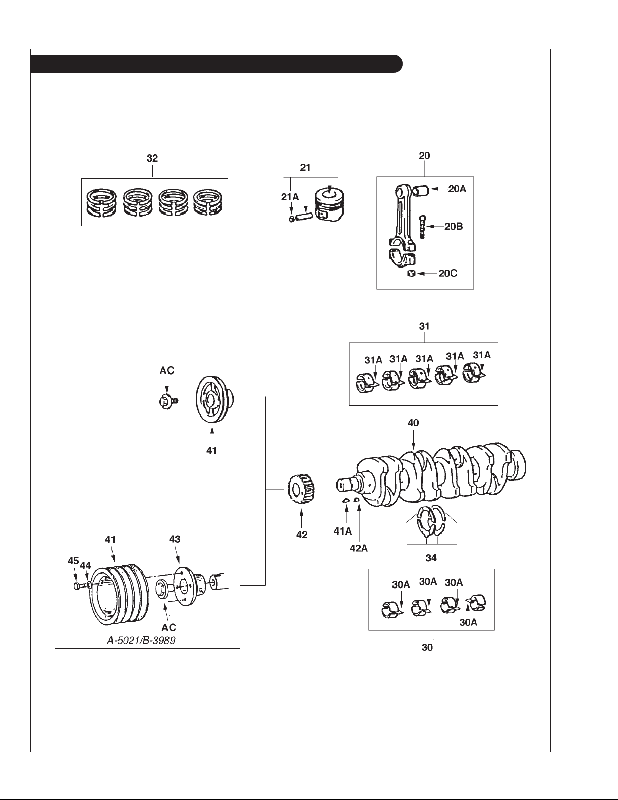
GROUP 1 – ENGINE
Crankshaft, Pistons & Connecting Rods
KEY PART NUMBER QTY DESCRIPTION ENGINE BLOCK S/N
20 13201-78300-71 4 Connecting Rod Assembly up to S/N - 0042812
20A 90384-32951-71 4 Wrist Pin Bushing 20B 13265-68010 8 Connecting Rod Bolt 20C 90179-12015 8 Nut -
21 13101-78700-71 4 Piston Assembly, Standard
13103-78700-71 4 Piston Assembly, 0.50 mm O/S
13105-78700-71 4 Piston Assembly, 1.00 mm O/S
21A 90521-34004 8 Snap Ring -
30 13204-78300-71 1 Connecting Rod Bearing Set, 0.25 mm, Undersize -
13205-78300-71 1 Connecting Rod Bearing Set, 0.50 mm, Undersize 13206-78300-71 1 Connecting Rod Bearing Set, 0.75 mm, Undersize 13207-78300-71 1 Connecting Rod Bearing Set, 1.00 mm, Undersize -
30A 13041-68040-01 4 Connecting Rod Bearing, Mark 1 - Standard -
13041-68040-02 4 Connecting Rod Bearing, Mark 2 - Standard -
Note: Standard size connecting rod bearings must be
Note: matched to rods stamped with Mark 1 or Mark 2.
31 11704-78700-71 1 Main Bearing Set, 0.25 mm, Undersize -
11705-78700-71 1 Main Bearing Set, 0.50 mm, Undersize 11706-78700-71 1 Main Bearing Set, 0.75 mm, Undersize 11707-78700-71 1 Main Bearing Set, 1.00 mm, Undersize -
31A 11701-78700-71 5 Main Bearing, Size 1 - Standard -
11701-78701-71 5 Main Bearing, Size 2 - Standard 11701-78702-71 5 Main Bearing, Size 3 - Standard -
Note: Standard size main bearings must be matched to cylinder blocks
Note: with bearing caps stamped with Mark 1, Mark 2 or Mark 3.
32 13011-78700-71 1 Piston Ring Set, Standard -
13013-78700-71 1 Piston Ring Set, 0.50 mm, Oversize 13015-78700-71 1 Piston Ring Set, 1.00 mm, Oversize -
34 11011-78300-71 1 Thrust Washer Set, Standard Only -
11012-78300-71 1 Thrust Washer Set O/S, 0.125 mm -
11013-78300-71 1 Thrust Washer Set O/S, 0.25 mm 40 13411-78700-71 1 Crankshaft 41 13471-78701-71 1 Crankshaft Pulley - Standard -
34-65401 1 Crankshaft Pulley - Optional -
41A 95161-10519 1 Key -
42 13521-78700-71 1 Crankshaft Timing Gear -
42A 95161-10519 1 Key -
43 34-65402 1 Mounting Flange 44 15-00701 4 Flat Washer M8 45 12-00712 4 Capscrew, Hex Head M8 x 1.25 x 25 mm -
AC 90105-16950-71 1 Retaining Bolt - Standard Pulley -
90105-16951-71 1 Retaining Bolt - Optional Pulley -
(includes Key #21A) -
(includes Key #21A) -
(includes Key #21A) -
P984 09/05
1 - 3
GROUP 1 – ENGINE
Crankshaft, Pistons & Connecting Rods
P984 09/05
1 - 4
A-5201 / B-3989 + 1301

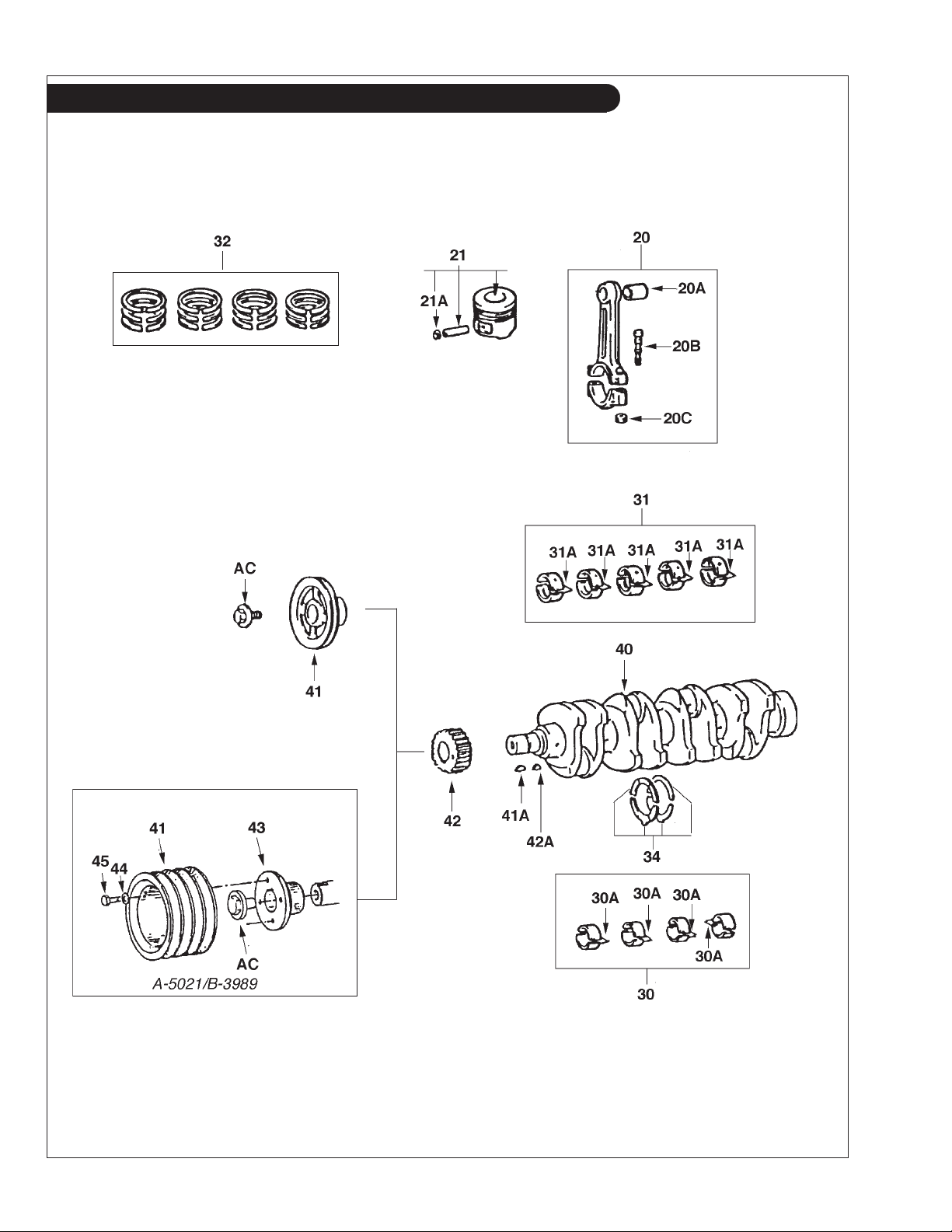
GROUP 1 – ENGINE
Crankshaft, Pistons & Connecting Rods
KEY PART NUMBER QTY DESCRIPTION ENGINE BLOCK S/N
20 13201-78300-71 4 Connecting Rod Assembly from S/N 0042813 20A 90384-32951-71 4 Wrist Pin Bushing 20B 13265-68010 8 Connecting Rod Bolt -
20C 90179-12015 8 Nut -
21 13101-78702-71 4 Piston Assembly, Standard
13103-78701-71 4 Piston Assembly, 0.50 mm O/S
13105-78701-71 4 Piston Assembly, 1.00 mm O/S
21A 90521-34004 8 Snap Ring -
30 13204-78300-71 1 Connecting Rod Bearing Set, 0.25 mm, Undersize -
13205-78300-71 1 Connecting Rod Bearing Set, 0.50 mm, Undersize 13206-78300-71 1 Connecting Rod Bearing Set, 0.75 mm, Undersize 13207-78300-71 1 Connecting Rod Bearing Set, 1.00 mm, Undersize -
30A 13041-68040-01 4 Connecting Rod Bearing, Mark 1 - Standard -
13041-68040-02 4 Connecting Rod Bearing, Mark 2 - Standard -
Note: Standard size connecting rod bearings must be
Note: matched to rods stamped with Mark 1 or Mark 2.
31 11704-78700-71 1 Main Bearing Set, 0.25 mm, Undersize -
11705-78700-71 1 Main Bearing Set, 0.50 mm, Undersize 11706-78700-71 1 Main Bearing Set, 0.75 mm, Undersize 11707-78700-71 1 Main Bearing Set, 1.00 mm, Undersize -
31A 11701-78703-71 5 Main Bearing, Size 1 - Standard -
11701-78704-71 5 Main Bearing, Size 2 - Standard 11701-78705-71 5 Main Bearing, Size 3 - Standard 11701-78706-71 5 Main Bearing, Size 4 - Standard 11701-78707-71 5 Main Bearing, Size 5 - Standard 11701-78708-71 5 Main Bearing, Size 6 - Standard -
Note: Standard size main bearings must be matched to cylinder blocks
Note: with bearing caps stamped with Mark 1 through Mark 6.
32 13011-78701-71 1 Piston Ring Set, Standard -
13013-78701-71 1 Piston Ring Set, 0.50 mm, Oversize 13015-78701-71 1 Piston Ring Set, 1.00 mm, Oversize -
34 11011-78300-71 1 Thrust Washer Set, Standard Only -
11012-78300-71 1 Thrust Washer Set O/S, 0.125 mm -
11013-78300-71 1 Thrust Washer Set O/S, 0.25 mm 40 13411-78701-71 1 Crankshaft 41 13471-78701-71 1 Crankshaft Pulley - Standard -
34-65401 1 Crankshaft Pulley - Optional -
41A 95161-10519 1 Key -
42 13521-78701-71 1 Crankshaft Timing Gear -
42A 95161-10519 1 Key -
43 34-65402 1 Mounting Flange 44 15-00701 4 Flat Washer M8 45 12-00712 4 Capscrew, Hex Head M8 x 1.25 x 25 mm AC 90105-16950-71 1 Retaining Bolt - Standard Pulley -
90105-16951-71 1 Retaining Bolt - Optional Pulley -
(includes key #21A) -
(includes key #21A) -
(includes key #21A) -
P984 09/05
1 - 5
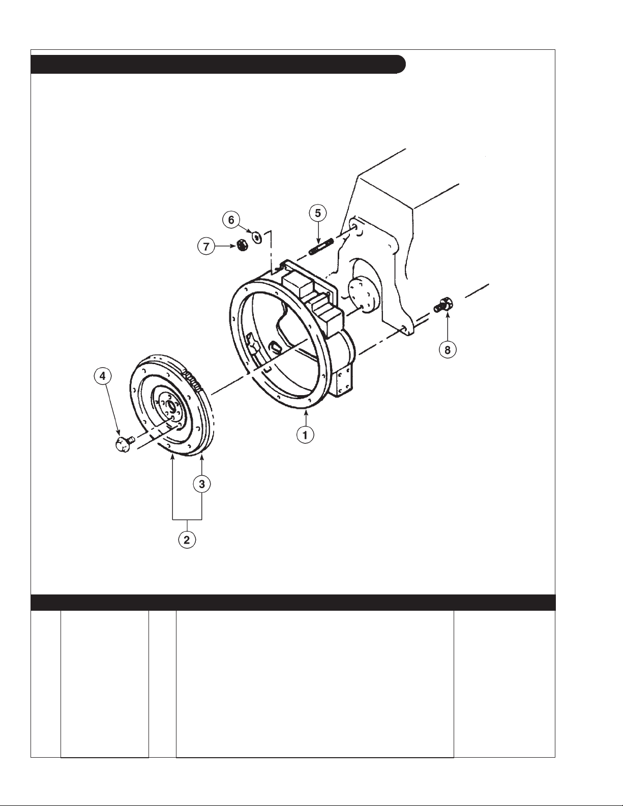
GROUP 1 – ENGINE
Flywheel and Housing
01-01: 3101
KEY PART NUMBER QTY DESCRIPTION SERIAL NUMBER
1 11351-78302-71 1 Flywheel Housing - SAE #4 2 13405-78302-71 1 Flywheel Assembly - SAE #10 3 13453-22060-71 1 Ring Gear - 108 Teeth 4 90105-12039 6 Washer Based Head Hexagon Bolt 5 90116-12950-71 2 Stud -
21-11002 ** Plug, 3/4-16
6 94512-01200 2 Washer 7 94115-51200 2 Nut 8 91619-61240 2 Bolt -
**As required.
(not shown) -
P984 09/05
1 - 6
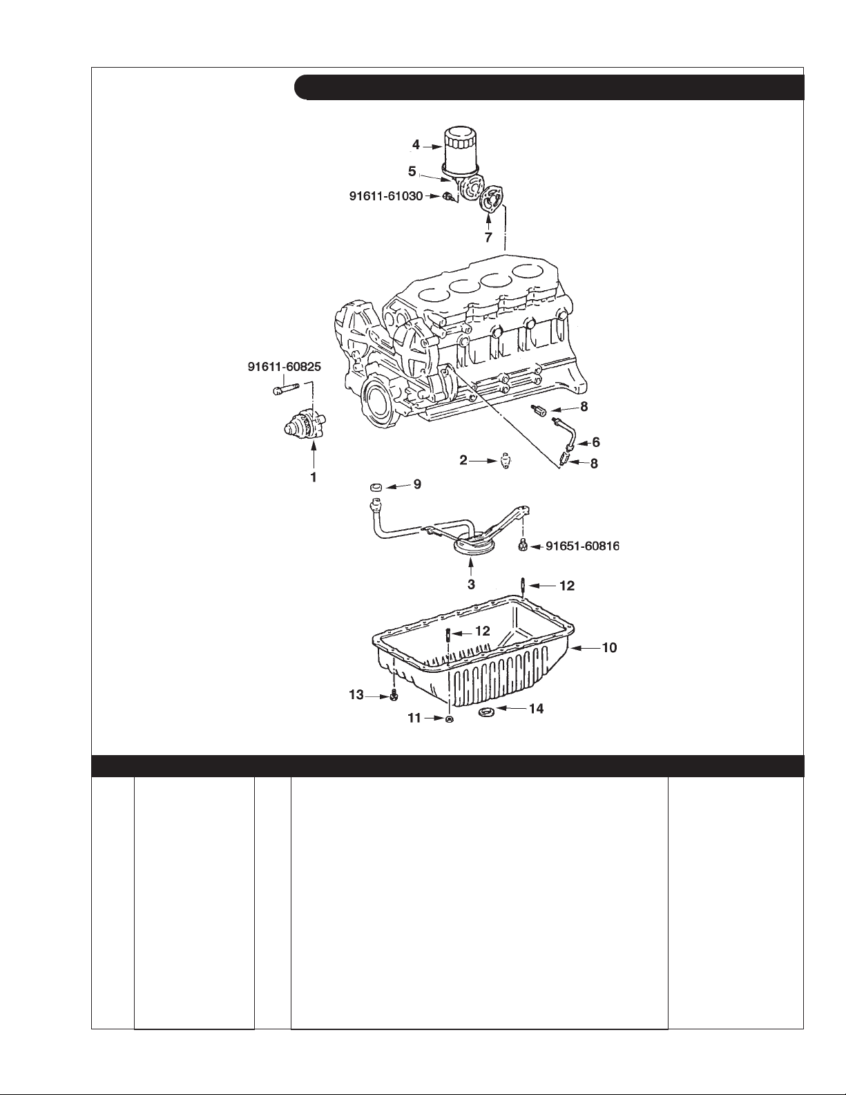
GROUP 1 – ENGINE
Lubrication System Components
01-04: 1105 / 1501 / 1502
KEY PART NUMBER QTY DESCRIPTION ENGINE BLOCK S/N
1 15100-78700-71 1 Oil Pump Assembly up to S/N - 004812
2 15310-78300-71 1 Oil Pressure Relief Valve (M18 Thread) 3 15104-78700-71 1 Strainer 4 24-05401 1 Oil Filter 5 15060-78300-71-A 1 Oil Filter Mount
6 15702-78700-71 1 Tube Assembly 7 15691-78301-71 1 Gasket 8 90404-10023 2 Fitting -
9 90430-17950-71 1 Gasket 10 12101-78700-71 1 Oil Pan 11 90179-08061 2 Nut 12 90116-08112 2 Stud 13 90119-08951 22 Bolt with Washer 14 90430-25003 1 Gasket -
(formerly #15060-78300-71) -
P984 09/05
1 - 7
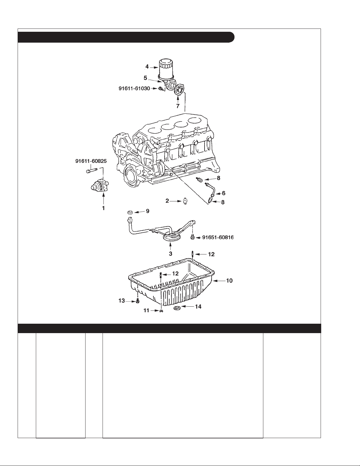
GROUP 1 – ENGINE
Lubrication System Components
01-04: 1105 / 1501 / 1502
KEY PART NUMBER QTY DESCRIPTION ENGINE BLOCK S/N
1 15100-78700-71 1 Oil Pump Assembly from S/N 0042813 2 15310-78700-71 1 Oil Pressure Relief Valve (M16 Thread) 3 15104-78700-71 1 Strainer 4 24-05401 1 Oil Filter 5 15608-78300-71 1 Oil Filter Mount -
6 15702-78700-71 1 Tube Assembly 7 15691-78301-71 1 Gasket 8 90404-10023 2 Fitting 9 90430-17950-71 1 Gasket -
10 12101-78700-71 1 Oil Pan 11 90179-08061 2 Nut 12 90116-08112 2 Stud 13 90119-08951 22 Bolt with Washer 14 90430-25003 1 Gasket -
P984 09/05
1 - 8
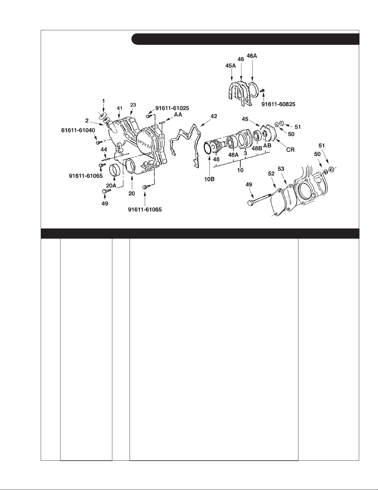
GROUP 1 – ENGINE
Timing Cover - P.T.O. & Rear Seal
A-5035 / C-2607 + 1106
KEY PART NUMBER QTY DESCRIPTION SERIAL NUMBER
1 12180-76002-71 1 Filler Cap 2 15773-78300-71 1 Filler Neck 3 11314-78700-71 1 PTO Housing -
10 11307-78302-71 1 PTO Assembly 9T
(includes keys #3, #48, #48A, #48B & #AB) -
10B 90301-81950-71 1 O-Ring -
20 11321-78306-71 1 Timing Gear Cover -
20A 90311-55950-71 1 Front Crankshaft Seal -
23 11311-78700-71 1 Timing Gear Case 41 11328-78700-71 1 Gasket, Timing Gear Cover 42 11312-78330-71 1 Gasket, Timing Gear Case 44 11391-46010 1 Timing Pointer 45 11-75401 1 Gasket, Hydraulic Pump Flange -
45A 11383-78700-71 1 Gasket, Rear Main Seal Retainer
46 11381-78700-71 1 Retainer, Rear Main Seal
(formerly #11381-78300-71) -
46A 00-05408 1 Wear Sleeve, Repair Type
90311-95951-71 1 Rear Main Seal
(previously #90311-95950-71) -
(formerly #11383-78330-71) -
(use with standard seal) -
48 13519-78302-71 1 PTO/Raw Water Pump Drive Gear 9T 48A 90363-35950-71 1 Bearing 48B 97103-06006 1 Bearing -
49 12-00837 2 Capscrew, Hex Head M10 x 1.5 x 150 mm -
50 15-00802 2 Lock Washer M10 -
51 14-00811 2 Hex Nut M10 x 1.5 -
52 28-75403 1 Cover, Keel Cooling without Raw Water Pump -
53 11-75402 1 Gasket -
AA 90250-08120 3 Dowel Pin AB 96150-03000 1 Snap Ring BC 90341-10002 1 Plug -
BJ 90340-11027 1 Gasket -
CR 28-75001 1 PTO Cover -
P984 09/05
1 - 9
GROUP 1 – ENGINE
Camshaft & Valve Train
P984 09/05
1 - 10
P984 01-06

GROUP 1 – ENGINE
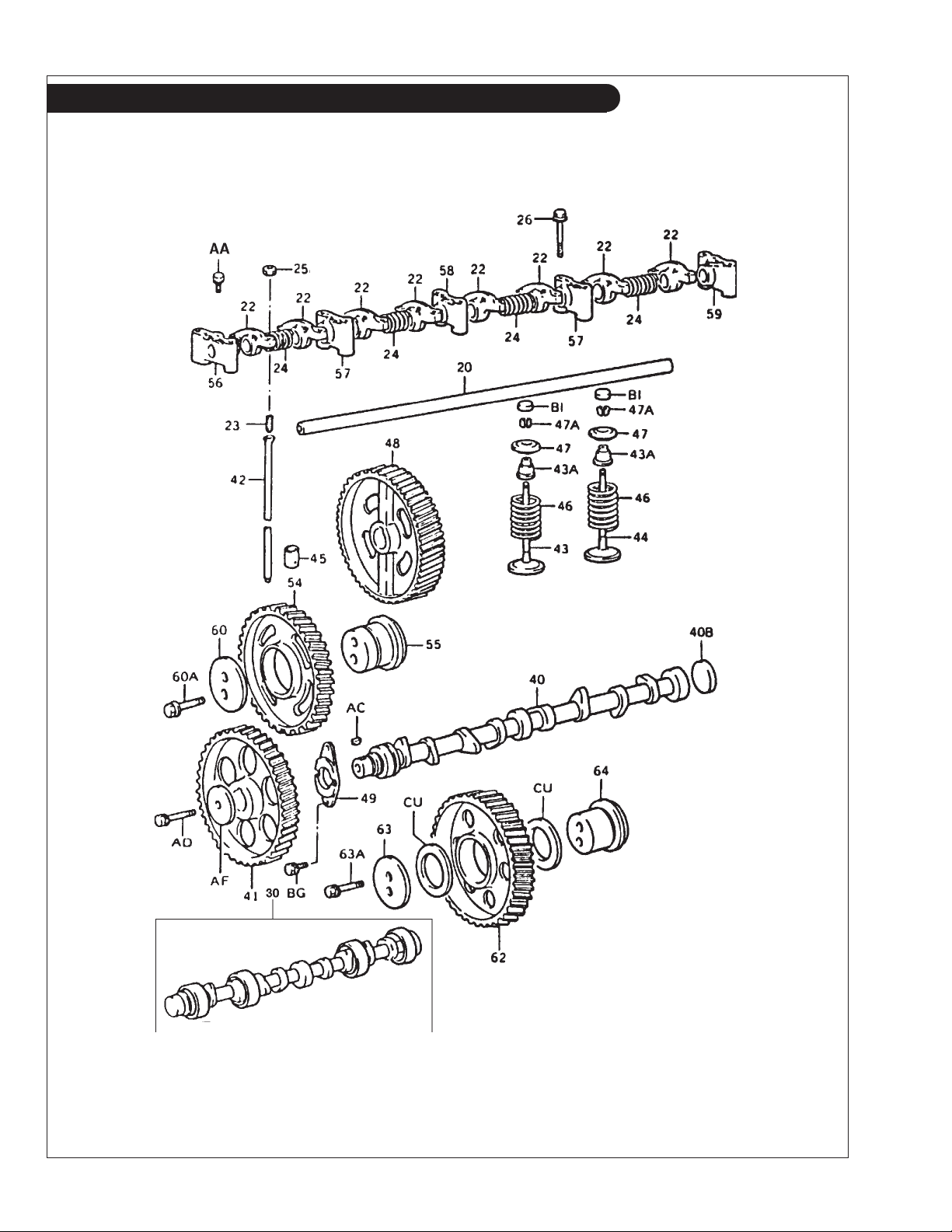
Camshaft & Valve Train
KEY PART NUMBER QTY DESCRIPTION ENGINE BLOCK S/N
20 13901-78300-71 1 Shaft up to S/N - 0042812
21 13810-78300-71 1 Rocker Shaft Assembly
22 13811-78300-71 8 Rocker Arm -
23 90913-05020 8 Valve Adjusting Screw -
24 90501-16163 4 Compression Spring -
25 90170-08094 8 Nut -
26 90099-04557 5 Capscrew, Hex Head M8 x 1.25 x 60 mm -
30 11802-78301-71 1 Camshaft Bearing Set, Standard -
11803-78300-71 1 Camshaft Bearing Set, 0.125 mm 11804-78300-71 1 Camshaft Bearing Set, 0.25 mm -
40 13511-78300-71 1 Camshaft 40B 90331-55950-71 1 Plug -
41 13523-78700-71 1 Camshaft Timing Gear -
42 13781-78300-71 8 Push Rod -
43 13711-78300-71 4 Intake Valve 43A 90913-02044 8 Valve Stem Oil Seal -
44 13715-78300-71 4 Exhaust Valve -
45 13751-44030 8 Lifter, Standard -
13755-47011 8 Lifter O/S, 0.05 mm 46 90501-45228 8 Valve Spring 47 13741-46010 8 Valve Spring Retainer -
47A 90913-03018 16 Valve Lock -
48 13613-78700-71 1 Injection Pump Drive Gear
13613-78701-71 1 Injection Pump Drive Gear
49 13571-68010 1 Camshaft Thrust Plate 54 13525-78700-71 1 #1 Idler Gear 55 13581-78300-71 1 #1 Idler Gear Shaft 56 13951-78300-71 1 #1 Valve Rocker Support 57 13952-78300-71 2 #2 Valve Rocker Support 58 13953-78300-71 1 #3 Valve Rocker Support 59 13954-78300-71 1 #4 Valve Rocker Support 60 13572-78300-71 1 Idler Gear Thrust Plate -
60A 90105-10950-71 2 Washer Based Head Hexagon Bolt -
62 13509-78700-71 1 #2 Idler Gear Sub-Assembly 63 13573-78301-71 1 #2 Idler Gear Thrust Plate -
63A 90105-10950-71 2 Washer Based Head Hexagon Bolt -
64 13582-78700-71 1 #2 Idler Gear Shaft -
AA 91611-40816 2 Bolt AC 95161-10519 1 Key AD 91619-61250 1 Bolt with Washer -
AF 90201-12006 1 Washer -
BG 91611-61020 2 Bolt with Washer -
BI 13716-78300-71 8 Valve Stem Cap -
CU 90201-50950-71 2 Washer -
(includes keys 20, 22-25, & 56-59) -
(Generator Drive Units) -
(Propulsion Units) -
P984 09/05
1 - 11
GROUP 1 – ENGINE
Camshaft & Valve Train
P984 09/05
1 - 12
P984 01-06

GROUP 1 – ENGINE
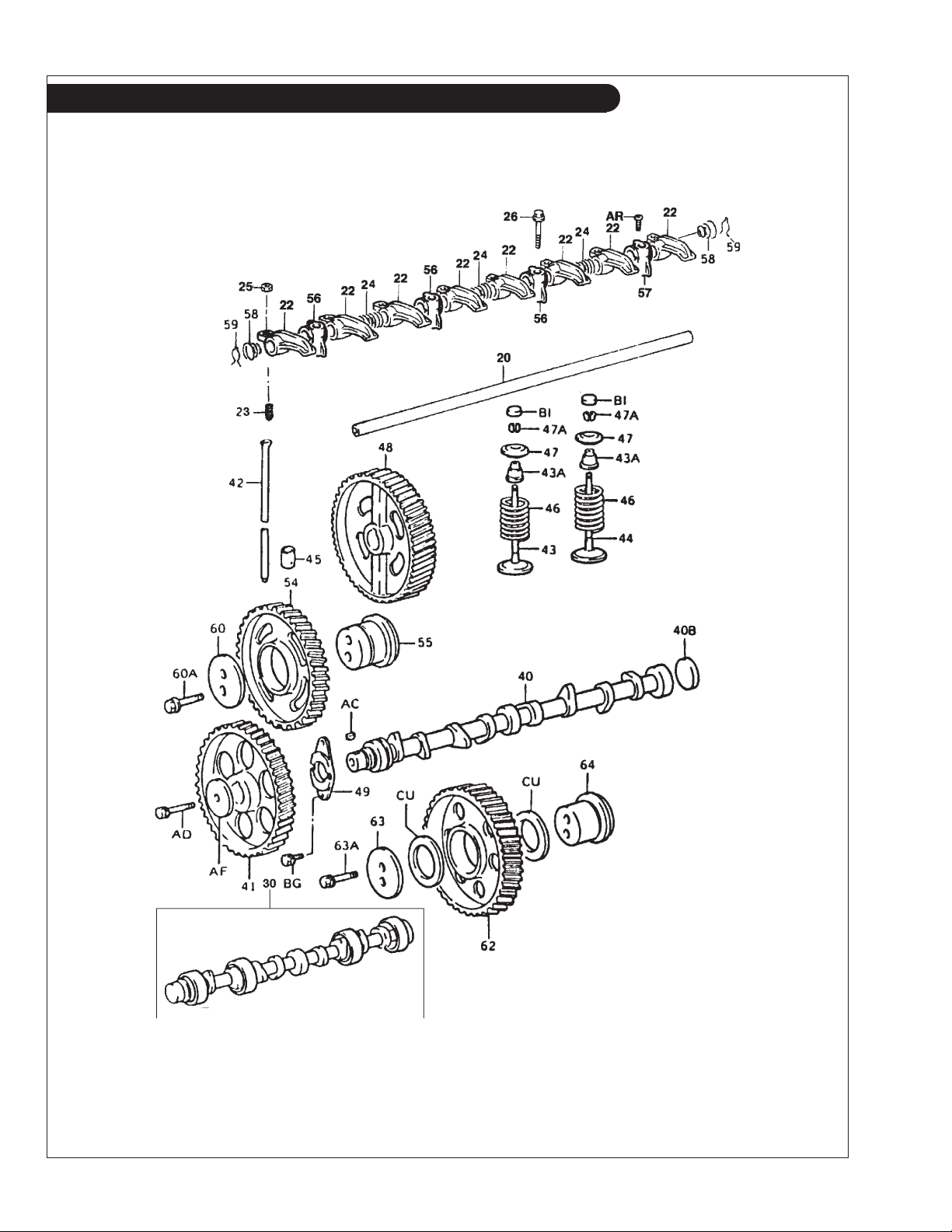
Camshaft & Valve Train
KEY PART NUMBER QTY DESCRIPTION ENGINE BLOCK S/N
20 13901-78700-71 1 Shaft from S/N 0042813 21 13810-78700-71 1 Rocker Shaft Assembly
22 13811-78300-71 8 Rocker Arm 23 90913-05020 8 Valve Adjusting Screw 24 90501-16098 3 Compression Spring 25 90170-08094 8 Nut 26 91512-61060 4 Capscrew, Hex Head M10 x 1.25 x 60 mm 30 11802-78301-71 1 Camshaft Bearing Set, Standard -
11803-78300-71 1 Camshaft Bearing Set, 0.125 mm -
11804-78300-71 1 Camshaft Bearing Set, 0.25 mm 40 13511-78700-71 1 Camshaft -
40B 90331-55950-71 1 Plug -
41 13523-78701-71 1 Camshaft Timing Gear 42 13781-78300-71 8 Push Rod 43 13711-78300-71 4 Intake Valve -
43A 90913-02044 8 Valve Stem Oil Seal -
44 13715-78300-71 4 Exhaust Valve 45 13751-78700-71 8 Lifter -
13755-47011 8 Lifter O/S, 0.05 mm 46 90501-40950-71 8 Valve Spring 47 13741-46010 8 Valve Spring Retainer -
47A 90913-03018 16 Valve Lock -
48 13613-78702-71 1 Injection Pump Drive Gear
13613-78703-71 1 Injection Pump Drive Gear
49 13571-68010 1 Camshaft Thrust Plate 54 13525-78701-71 1 #1 Idler Gear 55 13581-78300-71 1 #1 Idler Gear Shaft 56 13951-78700-71 3 Rocker Support 57 13952-78700-71 2 Rocker Support 58 90502-16004 1 Spring 59 90524-15008 2 Spring Clip 60 13572-78300-71 1 Idler Gear Thrust Plate -
60A 90105-10950-71 2 Washer Based Head Hexagon Bolt -
62 13525-78701-71 1 #2 Idler Gear 63 13573-78301-71 1 #2 Idler Gear Thrust Plate -
63A 90105-10950-71 2 Washer Based Head Hexagon Bolt -
64 13582-78700-71 1 #2 Idler Gear Shaft -
AR Bolt AA 91611-40816 2 Bolt AC 95161-10519 1 Key AD 91619-61250 1 Bolt with Washer -
AF 90201-12006 1 Washer -
BG 91611-61020 2 Bolt with Washer -
BI 13716-78300-71 8 Valve Stem Cap -
CU 90201-50950-71 2 Washer -
(includes keys 22-25, & 56-59) -
(Generator Drive Units) -
(Propulsion Units) -
P984 09/05
1 - 13
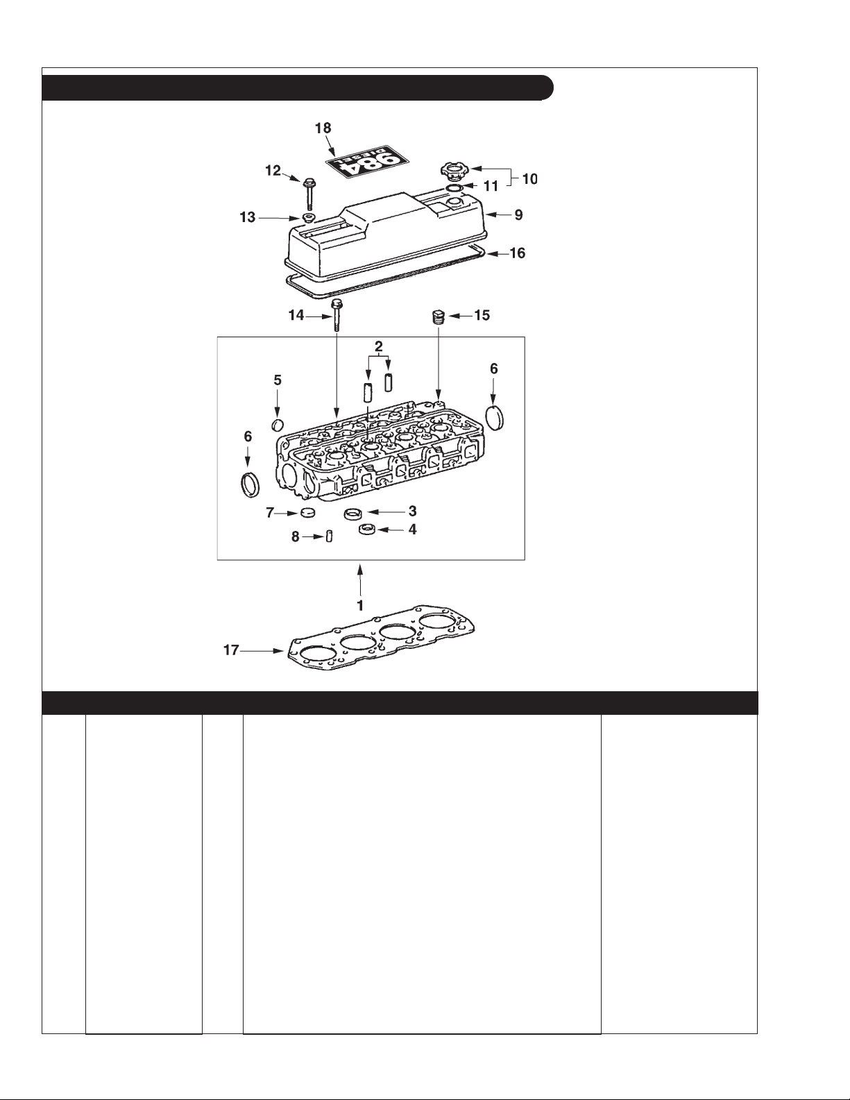
GROUP 1 – ENGINE
Cylinder Head & Valve Cover
P984 01-09: 1104
KEY PART NUMBER QTY DESCRIPTION ENGINE BLOCK S/N
1 11101-78302-71 1 Cylinder Head
(includes keys #2 - #8) up to S/N - 0042812
2 11122-46010 8 Valve Guide 3 11131-68020 4 Intake Valve Seat 4 11135-68010 4 Exhaust Valve Seat 5 96411-43000 8 Expansion Plug 6 96411-45000 2 Expansion Plug 7 96411-43000 3 Expansion Plug 8 90440-15141 4 Tube 9 11201-78300-71 1 Rocker Arm Cover -
10 12180-13030 1 Oil Filter Cap
(includes key #11) -
11 90430-37140 1 Gasket 12 91631-40840 4 Capscrew, Hex Head w/Washer M8 x 1.25 x 40 mm 13 90210-08007 4 Sealing Washer 14 90910-02070 18 Head Bolt M12 x 1.25 x 117 mm 15 90345-54005 1 Plug 16 11213-78300-71 1 Rocker Arm Cover Gasket 17 11115-78701-71 1 Cylinder Head Gasket
(formerly #11115-78700-71) -
18 00-05404 1 Label -
P984 09/05
1 - 14
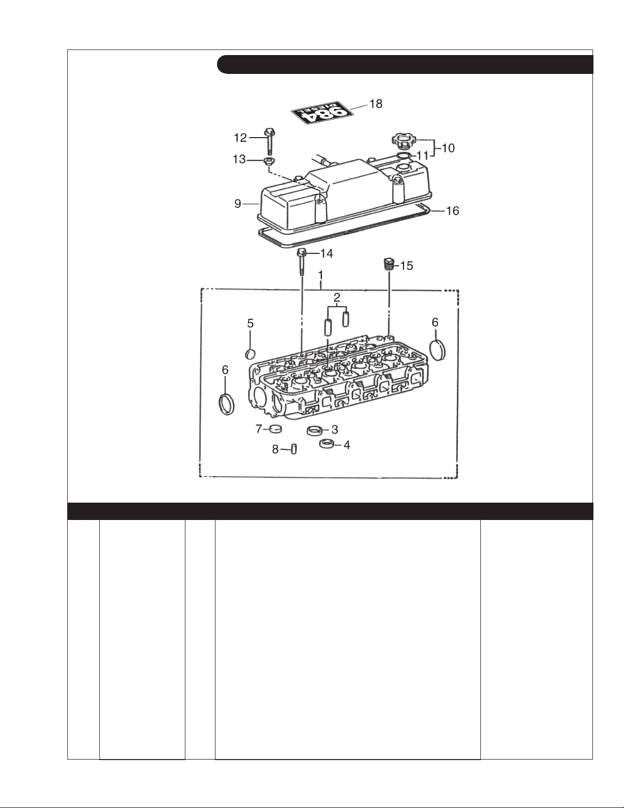
GROUP 1 – ENGINE
Cylinder Head & Valve Cover
P984: TOYOTAROCKERCOVER
KEY PART NUMBER QTY DESCRIPTION ENGINE BLOCK S/N
1 11101-78700-71 1 Cylinder Head
2 11122-46010 8 Valve Guide 3 11131-68020 4 Intake Valve Seat 4 11135-68010 4 Exhaust Valve Seat 5 96411-43000 8 Expansion Plug 6 96411-45000 2 Expansion Plug 7 96411-43000 3 Expansion Plug 8 90440-15141 4 Tube -
9 11201-78700-71 1 Rocker Arm Cover 10 12180-13030 1 Oil Filter Cap
11 90430-37140 1 Gasket 12 91621-60865 4 Capscrew, Hex Head w/Washer M8 x 1.25 x 65 mm 13 90210-08007 4 Sealing Washer 14 90910-02070 18 Head Bolt M12 x 1.25 x 117 mm 15 90345-54005 1 Plug 16 11213-78700-71 1 Rocker Arm Cover Gasket 17 11115-78701-71 1 Cylinder Head Gasket 18 00-05404 1 Label -
(includes keys #2 - #8) from S/N 0042813 -
(includes key #11) -
P984 09/05
1 - 15
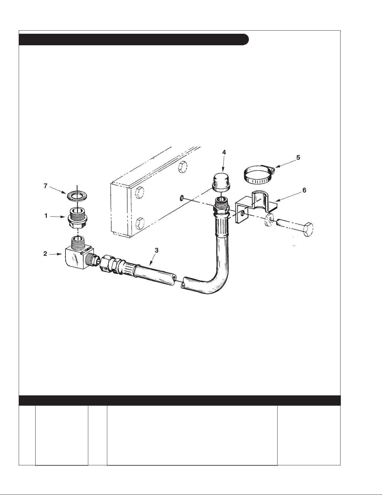
GROUP 1 – ENGINE
Oil Drain Kit
Northern Lights Application
A-4348 / B-3669
KEY PART NUMBER QTY DESCRIPTION SERIAL NUMBER
1 36-75402 1 Oil Pan Drain Fitting 2 21-62508 1 Male Elbow 90° 3/8 NPT x 1/2-37T -
3 18-75400 1 Hose Assembly 1/2" ID x 1/2 NPT x 1/2-37T 4 21-00003 1 Pipe Cap, 1/2 NPT 5 19-00010 1 Hose Clamp 6 23-75415 1 Oil Drain Hose Support Bracket 7 90430-25013 1 Gasket -
P984 09/05
1 - 16

GROUP 1 – ENGINE
Notes
P984 09/05
1 - 17
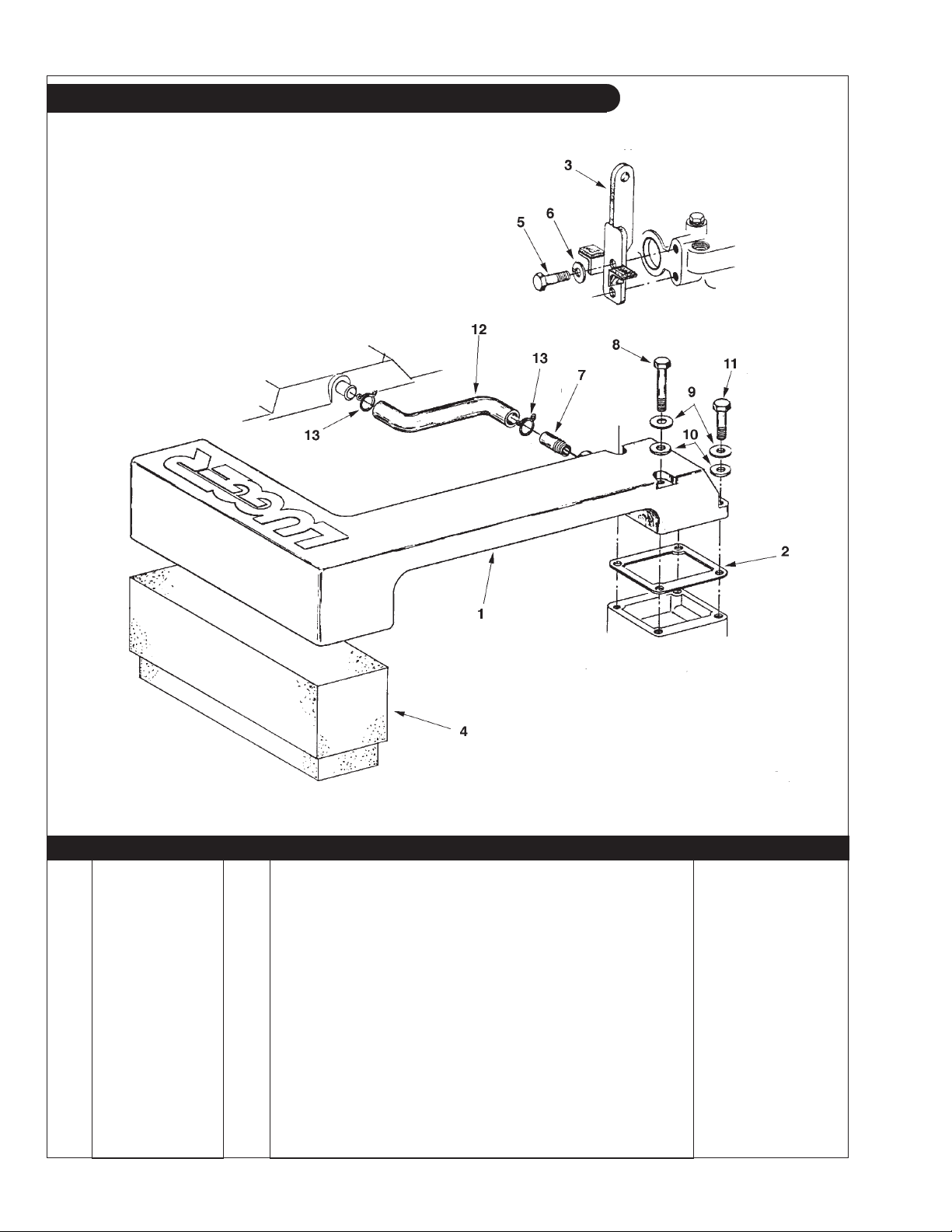
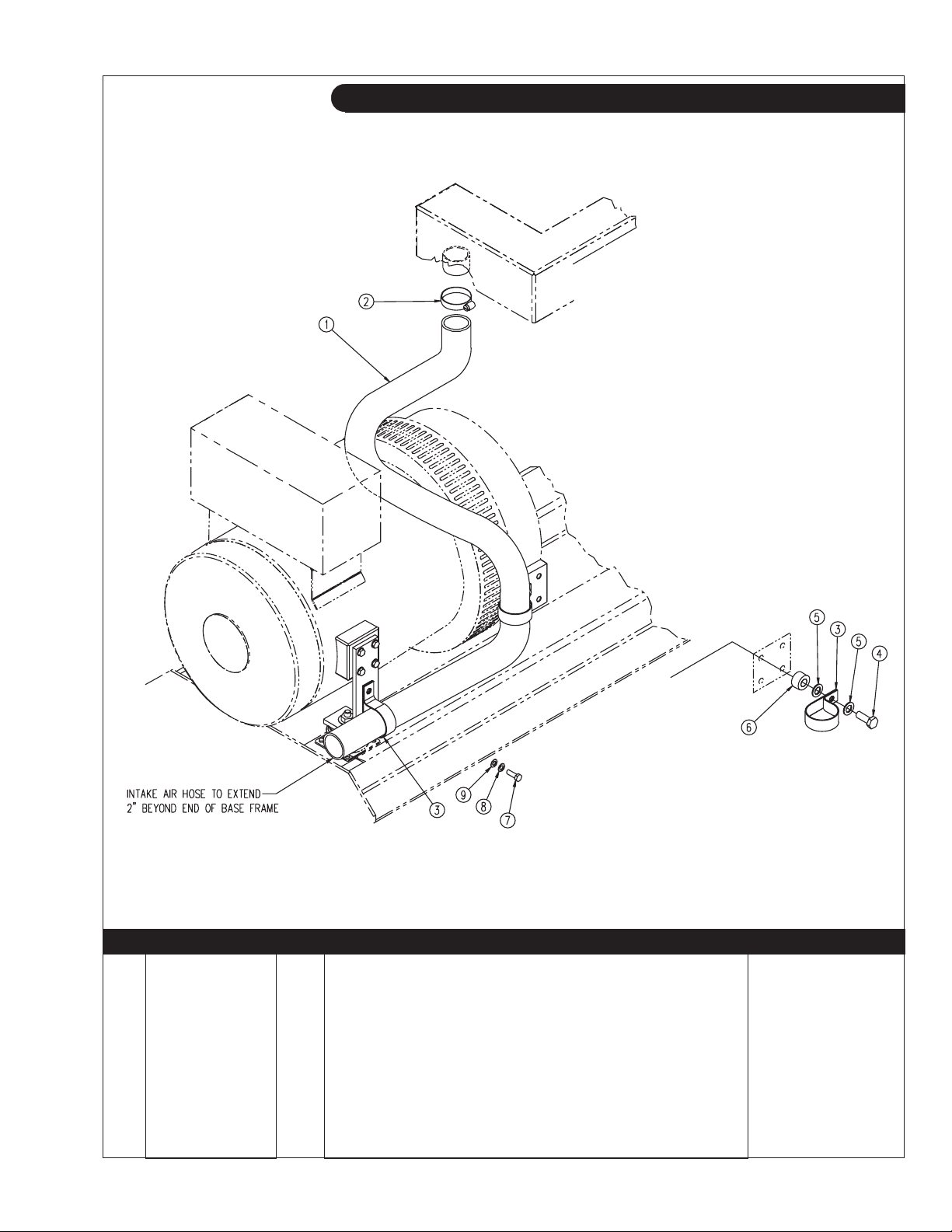
GROUP 2 – INTAKE & EXHAUST SYSTEM
Air Intake & Vent Hose
Early Production Generator Sets and L984D
A-7044, A-7378, A-7869 / C-2334A
KEY PART NUMBER QTY DESCRIPTION SERIAL NUMBER
1 10-25401 1 Air Intake Manifold
10-25402 1 Air Intake Manifold
(Marine) -
(Lugger) -
2 11-25400 1 Gasket 3 00-75402 1 Rear Lifting Eye 4 24-25401 1 Air Filter Element
24-25402 1 Air Filter Element
(Lugger) -
(Marine - see Intake Noise Reduction Assembly)
5 12-00809 2 Capscrew, Hex Head M10 x 1.25 x 25 mm 6 15-00802 2 Helical Lock Washer M10 7 21-25401 1 Male Connection 3/8 NPT x 5/8 HB 8 12-00754 2 Capscrew, Hex Head M8 x 1.25 x 85 mm -
9 15-00701 4 Flat Washer, M8 10 16-25400 4 O-Ring 11 12-00713 2 Capscrew, Hex Head M8 x 1.25 x 35 mm 12 12261-78301-71 1 Vent Hose 13 90467-23002 2 Hose Clamp -
P984 09/05
2 - 0
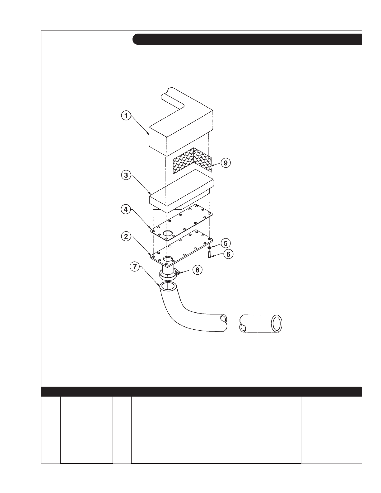
GROUP 2 – INTAKE & EXHAUST SYSTEM
Intake Noise Reduction
Marine Application - Early Production
P984 02-01: B-4821
KEY PART NUMBER QTY DESCRIPTION SERIAL NUMBER
1 10-25401 1 Intake Manifold 2 28-25401 1 Cover Plate 3 24-25402 1 Air Filter Element 4 11-25401 1 Gasket 7 18-25403 1 Hose, Air Intake 2" ID x 65" (1500 RPM units) -
18-25402 1 Hose, Air Intake 2" ID x 54" (1800 RPM units) 8 19-00032 1 Hose Clamp #32 9 24-25403 1 Screen -
P984 09/05
2 - 1
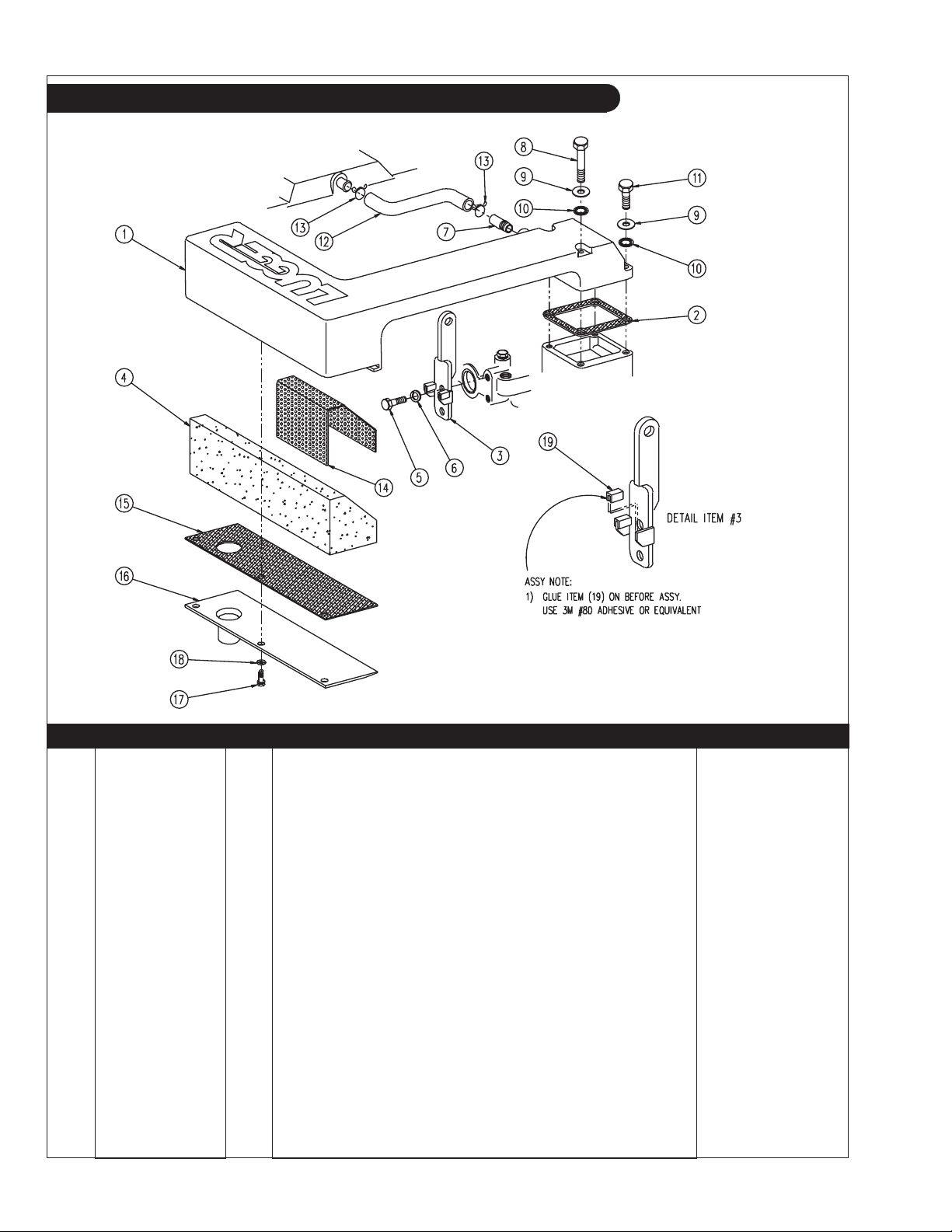
GROUP 2 – INTAKE & EXHAUST SYSTEM
Air Intake & Vent Hose
Marine Application - Late Production
A-7708 / C-4057
KEY PART NUMBER QTY DESCRIPTION SERIAL NUMBER
1 10-25402 1 Air Intake Manifold 2 11-25400 1 Gasket 3 00-75482 1 Lifting Eye, Rear 4 24-25402 1 Air Filter Element 5 12-00809 2 Capscrew, Hex Head M10 x 1.25 x 25 mm 6 15-00802 2 Lock Washer, Helical M10 7 21-25401 1 Nipple, Plain, BP, 3/8 NPT x 1-1/4 8 12-00754 2 Capscrew, Hex Head M8 x 1.25 x 85 mm -
9 15-00701 4 Flat Washer M8 10 16-25400 4 O-Ring, 8.5 mm x 18 mm x 3.2 mm 11 12-00713 2 Capscrew, Hex Head M8 x 1.25 x 35 mm 12 12261-78301-71 1 S-Hose 13 90467-23002 2 Hose Clamp 14 24-25405 1 Screen 15 11-25402 1 Gasket 16 28-25402 1 Plate 17 12-00209 3 Capscrew, Hex Head 5/16-18 x 3/4" 18 15-00203 3 Star Washer, Internal 5/16" 19 00-25401 ** Rubber Cushion Strip 7/8" LOA -
00-25402 ** Cushioned Steel U-Channel -
** As required.
P984 09/05
2 - 2
GROUP 2 – INTAKE & EXHAUST SYSTEM
Intake Noise Reduction
Marine Application - Late Production
A-8483, A-8498 / C-4063
KEY PART NUMBER QTY DESCRIPTION SERIAL NUMBER
1 18-25402 1 Air Intake Hose, 2" ID x 54" (1800 RPM units) -
18-25403 1 Air Intake Hose, 2" ID x 65" (1500 RPM units) 2 19-00032 1 Hose Clamp #32 3 19-71035 2 Adelle Clamp 2-14" ID x 1/2" Stud 4 12-09516 1 Capscrew, Hex Head 1/2-13 x 2" Stainless Steel 5 15-00508 2 Flat Washer 1/2 SAE Stainless Steel 6 21-21004 1 Spacer, BP. 1/2 SCHD 40 x 13/16" 7 12-00776 1 Capscrew, Hex Head M8 x 1.25 x 20 mm Stainless Steel 8 15-00705 1 Lock Washer, Helical M8 Stainless Steel 9 15-00706 1 Flat Washer M8 Stainless Steel -
P984 09/05
2 - 3
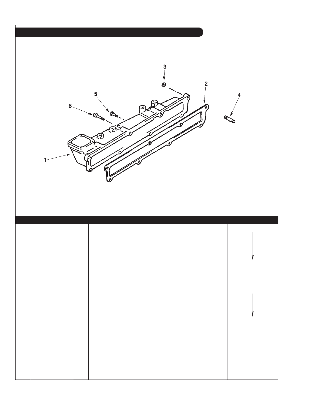
GROUP 2 – INTAKE & EXHAUST SYSTEM
Intake Manifold
P984 02-04: 1701
KEY PART NUMBER QTY DESCRIPTION ENGINE BLOCK S/N
1 17111-78300-71 1 Intake Manifold up to S/N -0042812
2 17171-78300-71 1 Intake Manifold Gasket
3 90179-08061 3 Lock Nut, Flanged M8 x 1.25
4 90116-08131 3 Stud M8 x 1.25 x 20 mm (30 mm LOA)
5 91611-60825 3 Capscrew, Hex Head with Washer M8 x 1.25 x 25 mm
6 91611-60865 3 Capscrew, Hex Head with Washer M8 x 1.25 x 65 mm
1 17111-78700-71 1 Intake Manifold from S/N 0042813 2 17171-78700-71 1 Intake Manifold Gasket
3 90179-08061 3 Lock Nut, Flanged M8 x 1.25
4 90116-08131 3 Stud M8 x 1.25 x 20 mm (30 mm LOA)
5 91611-60825 6 Capscrew, Hex Head with Washer M8 x 1.25 x 25 mm
P984 09/05
2 - 4

GROUP 2 – INTAKE & EXHAUST SYSTEM
Air Inlet
Commercial Application
A-5546/ C-2716
KEY PART NUMBER QTY DESCRIPTION SERIAL NUMBER
1 24-20001 1 Air Filter 2 31-25401 1 Air Inlet Adapter 3 11-25400 1 Gasket 4 12-00712 4 Capscrew, Hex Head M8 x 1.25 x 25 mm 5 15-00702 4 Lock Washer M8 6 18-71010 1 Hose, 5/8" ID x 11" 7 19-00008 2 Hose Clamp #8 8 19-00040 1 Hose Clamp #40 -
P984 09/05
2 - 5
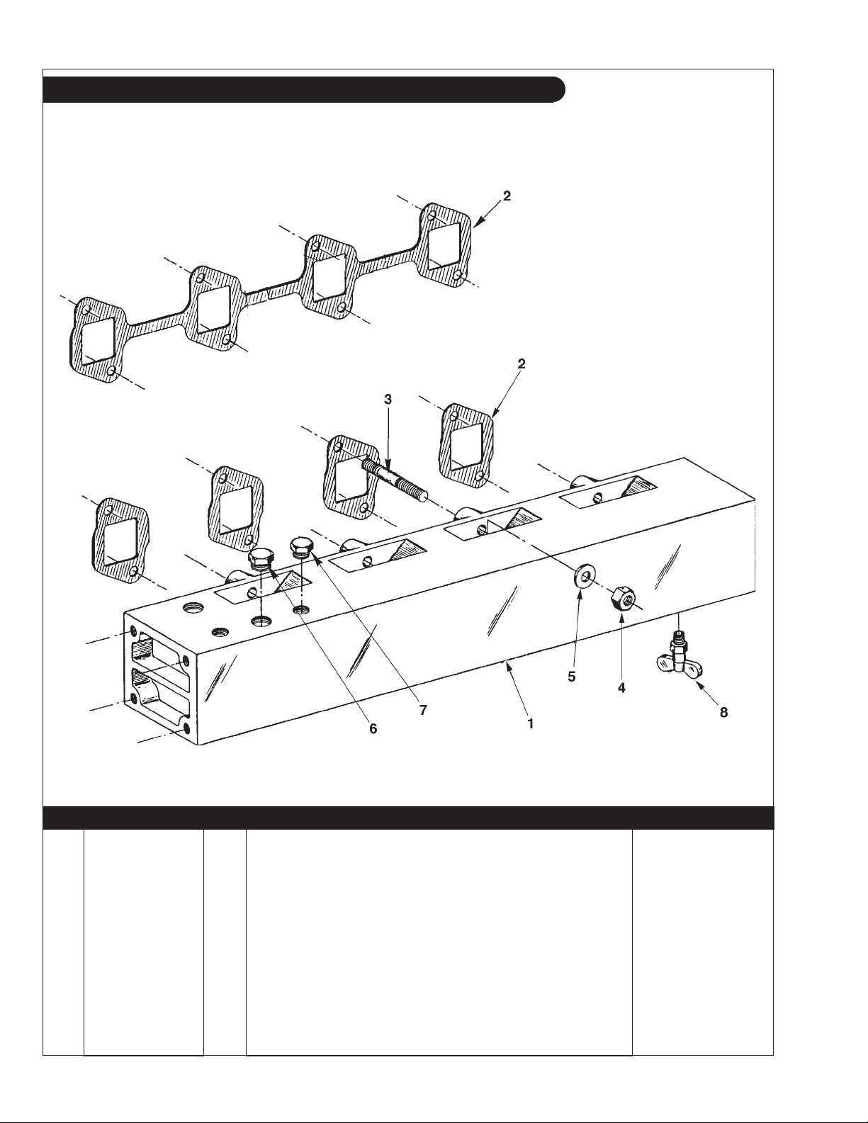
GROUP 2 – INTAKE & EXHAUST SYSTEM
Exhaust Manifold
A-4213 / C-2337
KEY PART NUMBER QTY DESCRIPTION SERIAL NUMBER
1 10-35400 1 Exhaust Manifold 2 11-35402 4 Exhaust Manifold Gasket -
17173-78300-71 1 Exhaust Manifold Gasket
(replaced by #11-35402)
3 13-35401 8 Stud, M10 x 1.25 x 35 mm (47 mm LOA) 4 14-00816 8 Hex Nut, M10 x 1.25
(14 mm Hex) -
5 15-00805 8 Flat Washer, M10 6 21-00530 ** Hex Plug, brass 1/2 NPT 7 21-31003 ** Hex Plug, brass 3/8 NPT 8 21-10002 1 Drain Cock 1/4 NPT 9 17-10006 1 Expansion Plug 3/4"
**As required
(not shown) -
P984 09/05
2 - 6
 Loading...