How it Works
Log In / Sign Up
Buy Points
How it Works
FAQ
Contact Us
Questions and Suggestions
Users
Northern Lights
Loading...
L
L1276A2
L6108
L6125
L6140A
2
L6140AL
L6140AL2
2
L6170A
L844D
L944D
3
L984
LC6108
Lugger 0844K
Lugger L984
Lugger M20CL
Lugger M20CR
Lugger M30C
Lugger M30CW
Lugger M33CW
Lugger M673D
Lugger M673L
Lugger M673M
Lugger M773LW
Lugger M773LW2
Lugger M773LW3
Lugger M843NW2
Lugger M843NW3
Lugger M844K
Lugger M844LK
Lugger M944W
Lugger M984K
Lugger M984W
Lugger ML984
Lugger OM673
Lugger OM773LW2
Lugger OM843NW2
Lugger OM944W
Lugger ONL753W2
Lugger P984
LX-E
LX-E 34E
M
M1064A
3
M1064D
3
M1064H
2
M1064T1
3
M1064T2
3
M1066A1
2
M1066A2
2
M1066A3
2
M1066H
M1066T
2
M1276A1
M1276A2
M175C2
M20CL
M20CR2
M20CRW2
M20CRW3
2
M30C
M30CW
2
M30CW3
2
M33C
M33CW
M38CR2
2
M40C2
3
M55C2
3
M6108
M6125
M6140AL
2
M6140AL2
M6170A
M65C13
M65C2
3
M673D
2
M673L
2
M673L2
M673L3
3
M673LD2
M673LD3
3
M673M
M753
M753W
M753W2
M773L
M773LK
3
M773LW
M773LW2
2
M773LW3
4
M843
M843JK
M843NK
M843NW2
M843NW3
4
M843W3
M844
M844DW3
M844K
M844K2
M844L
M844LK
M844LK2
Loading...
Loading...
Nothing found
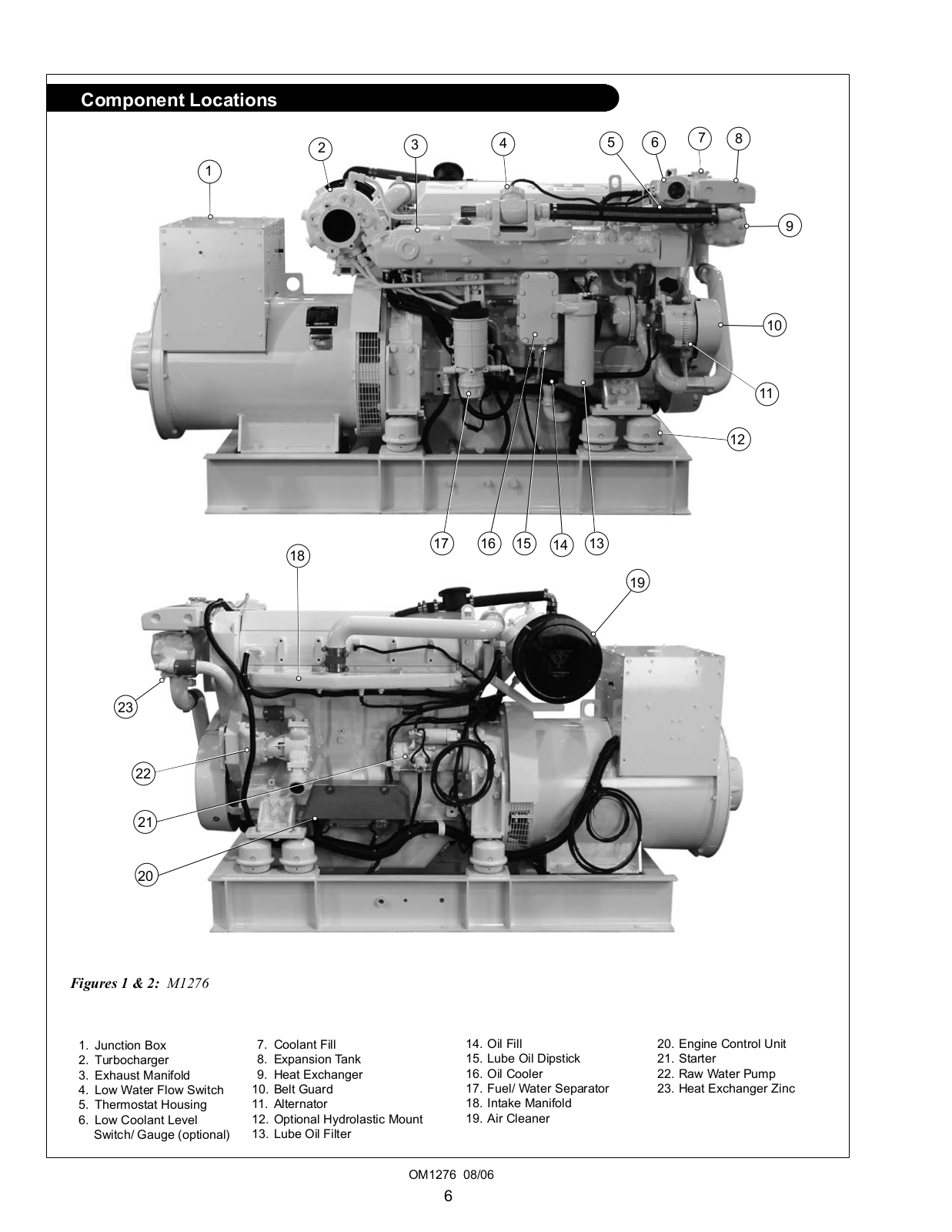
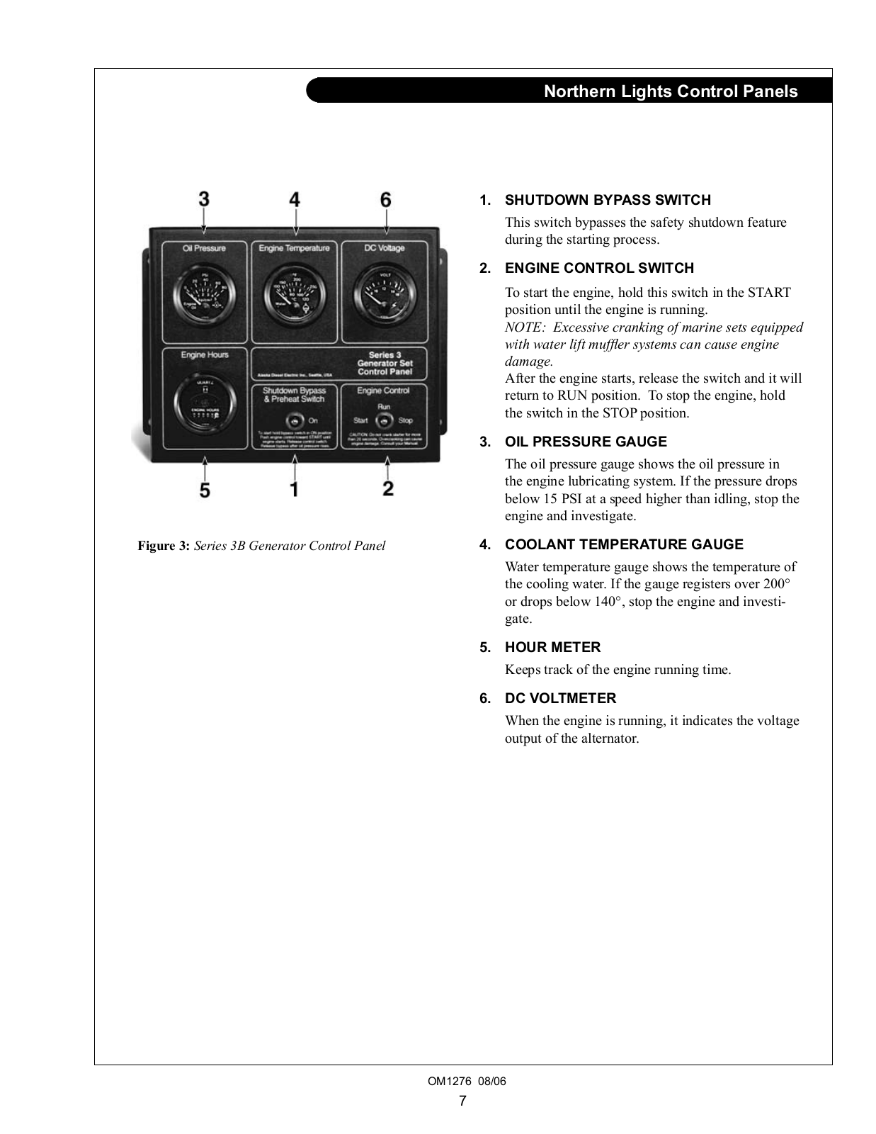
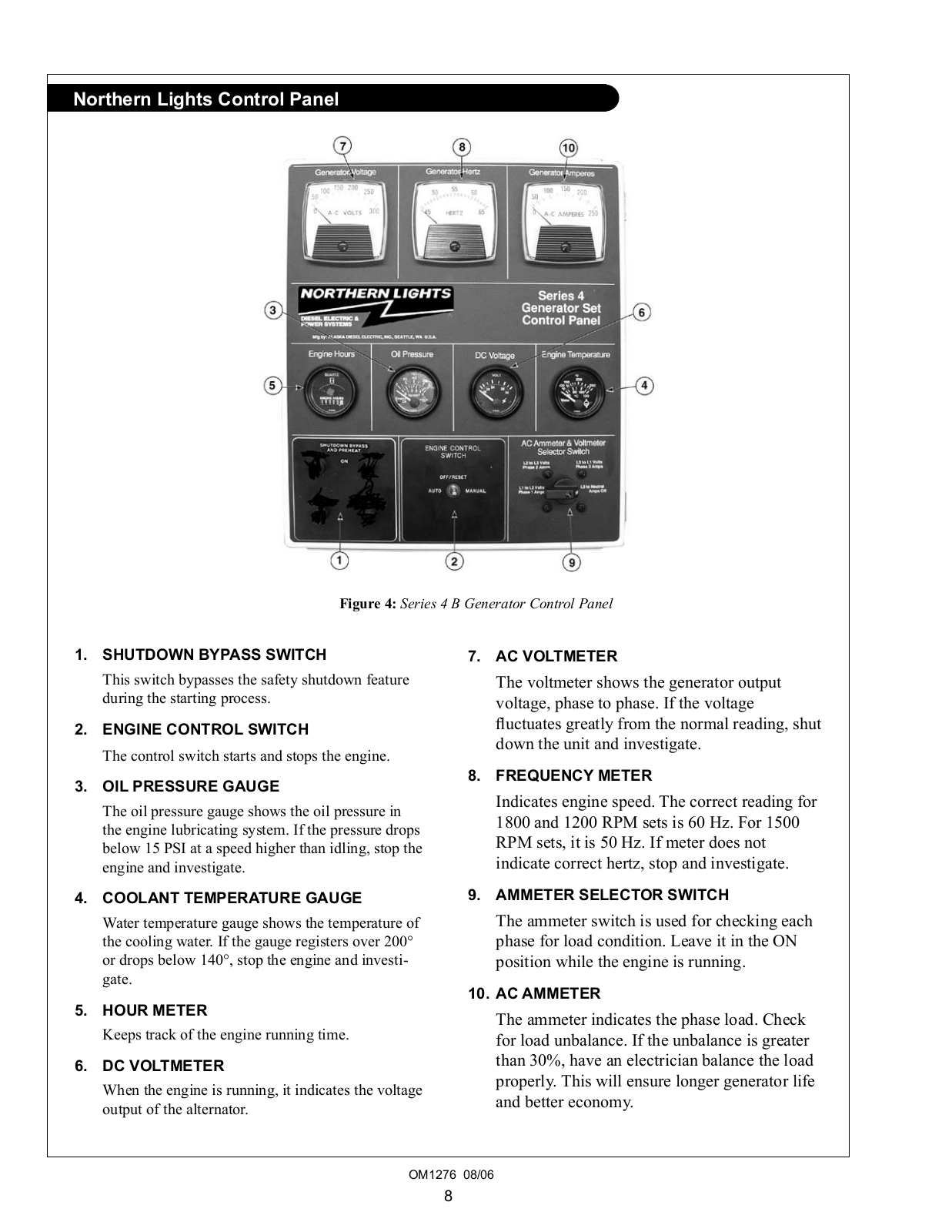
M1276A1
Operator's Manual
31 pgs
1.6 Mb
0
Table of contents
Loading...
Northern Lights M1276A1, M1276A2 Operator's Manual
...
Northern Lights Operator's Manual
Download
Specifications and Main Features
Frequently Asked Questions
User Manual
Download
Loading...
+
hidden pages
Unhide
You need points to download manuals.
1 point = 1 manual.
You can buy points or you can get point for every manual you upload.
Buy points
Upload your manuals