

Northern Lights LX-E, LX-E 34E Installation Manual
OPERATOR’S
OPERATOR’S
&
&
MANUAL
MANUAL
LX-E A.C. GENERATOR
For Generator Model:
LX-E 34 E
PARTS
PARTS
— CALIFORNIA —
Proposition 65 Warning:
Diesel engine exhaust and some of its constitu-
ents are known to the State of California to cause
cancer, birth defects, and other reproductive harm.
Northern Lights
4420 14th Avenue N.W.
Seattle, WA 98107
Tel: (206) 789-3880
Fax: (206) 782-5455
Copyright ©2010 Northern Lights, Inc.
All rights reserved. Northern Lights™, and
the Northern Lights logo are trademarks of
Northern Lights, Inc.
Printed in U.S.A.
PART NO.: OLXE 03/10

OPERATOR’S & PARTS
MANUAL OLXE
For Generator Model:
LX-E 34E
Read this manual thoroughly before starting your equipment.
This manual contains information needed to operate your set correctly and safely.
Table of Contents
Introduction. .....................................................................4
Safety Rules .....................................................................4
Models and Serial Numbers ...........................................5
Mechanical Construction .................................................6
INITIAL INSPECTION AND COUPLING
Initial Inspection..........................................................6
Coupling with Prime Mover........................................6
Grounding ...................................................................6
PERFORMANCE AND FUNCTION
Excitation System........................................................7
Automatic Voltage Regulator (AVR) ..........................7
Under Speed Protection...............................................7
Rotary Rectifi er and Surge Suppressor .......................7
CHARACTERISTICS
Voltage Regulation ......................................................8
Response .....................................................................8
Voltage Stability ..........................................................8
Short Circuit ................................................................8
Phase Rotation .............................................................8
OPERATION - GENERATOR SET
Starting ........................................................................9
Voltage Adjustment .....................................................9
Running .......................................................................9
Stopping ......................................................................9
OPERATION - VOLTAGE REGULATOR
Safety Rules ................................................................9
Operation ....................................................................9
Adjustment ..................................................................9
MAINTENANCE
Bearing Inspection ................................................... 10
Insulation Resistance Measurement Method ........... 10
Rotating Rectifi er Assembly ................................... 10
Parts Replacement Method ...............................10 - 11
Automatic Voltage Regulator Maintenance ..............11
SPECIFICATIONS
Generator Specifi cations.......................................... 12
Voltage Regulator Specifi cations ............................. 13
TROUBLESHOOTING ............................................. 14
STANDARD VOLTAGE SELECTION TABLE .........8
It may not be reproduced in whole or in part without the written permission of Northern Lights, Inc.
© Northern Lights, Inc. 2010. All rights reserved. Litho U.S.A. Publication number OLXE 03/10
PARTS LIST ....................................................... 15 - 16
WIRING DIAGRAM
AVR DST-100-2FAK ............................................. 17
Connection Schematic ............................................. 18
Proprietary Information
This publication is the property of Northern Lights, Inc.
OLXE 03/10
3

Introduction
This manual describes procedures for operation,
maintenance, inspection and adjustment. It will help the
operator realize peak performance through effective,
economical and safe operation.
• Read this manual carefully BEFORE operating the
generator.
• Study this manual until proper operation becomes
personal habit.
• Operation, inspection, and maintenance should be
carried out carefully. Safety must be given the fi rst .
priority.
Safety Rules
• To insure years of trouble-free operation, the
specifi ed maintenance is important and should be
performed.
• Electrical equipment should always be kept
clean. Oil, dust, moisture and salt are all harmful
to genera tors.
• Insulation Resistance and Dielectric: When
measuring insulation resistance and dielectric, be
sure to disconnect the AVR and rectifi er.
• Be sure that the regulator is shut off by switching the
CPR (circuit breaker) on the AVR to the off position
when the unit is run ning at less than rated speed, or
when the unit is to be run but no power generation is
required.
• Before starting your generator, be sure oper ating
conditions are safe.
• Ventilation: When selecting the installation site, be
sure that the area is well ventilated and that ambient
temperature does not exceed 40°C.
• Be sure to provide generator with cover and
protection when op erating outside.
LX-E Series AC generators are based on
BS 4999 part 20 and IEC34-5, IP22.
• Be careful with electricity. Do not touch rotating
parts.
• Ambient Environmental Conditions
a) Gas: Do not use in an environment of corrosive
or fl ammable gas (gasoline, hydrogen sulfi de,
meth ane gas, etc.)
b) Sandy Dust: Do not use equipment in places
with excessive sand and dust.
c) Humidity: Do not use in very humid
environments for long periods of time.
d) Salt/Seawater: Protect your generator from
exposure to salt, water, and water vapor.
OLXE 03/10
4
Model and Serial Numbers
GENERATOR END MODEL NUMBER
Generator Set Model No ....................... Generator Model
M944T ...........................................................LX-E 34E
SERIAL NUMBERS
• When referencing Northern Lights equip ment by serial
number, it is important to differentiate between the engine,
generator end, and generator set serial numbers.
• The engine serial number is either on a metal tag or stamped
directly into the engine block.
• The generator END serial number is on a metal tag attached
to the generator end.
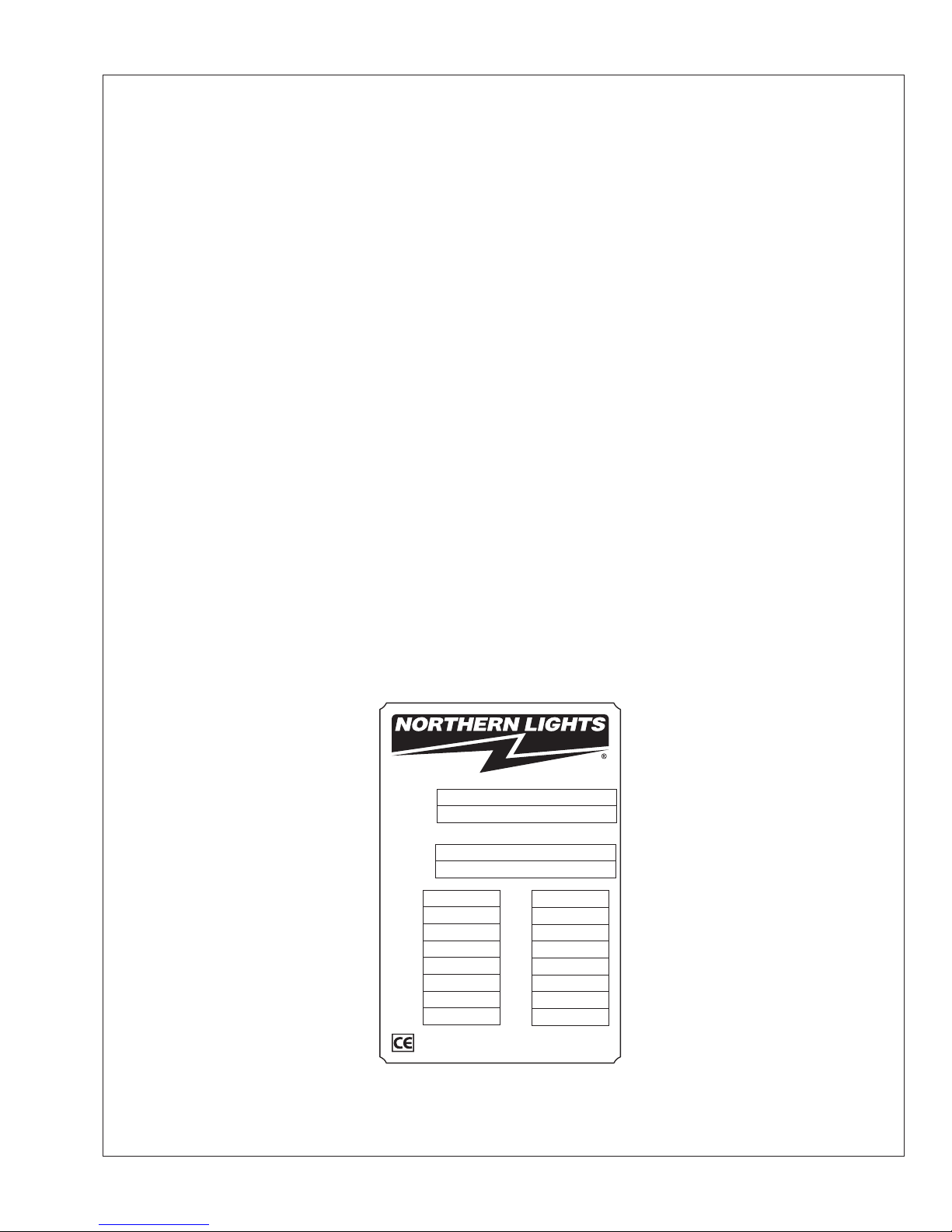
• The generator SET serial number is on a separate metal tag
attached to the generator end. It may be a fi ve by one inch tag
installed directly below the gen erator end tag. Or, it may look
like the illustrations below. Please use the generator SET number
in cor respondence or when ordering parts.
Generator Set Data
Set Serial
Set Model
AC Generator Data
Model No.
Serial No.
DUTY
KW
KVA
RPM
HERTZ
PHASE
°C RISE
RULE
Northern Lights, Inc., WA USA
www.northern-lights.com
WIRE
INSUL
AMB°C
PF
VOLTS
VOLTS
AMPS
AMPS
Figure 1: Generator Set Serial Number Plate
OLXE 03/10
5

Mechanical Construction
STATO R
The stator frame is fabricated from rolled steel. The
round construction provides rigidity and strength to
resist excessive mechanical shocks. The stator core is
made of high quality silicon steel plates coated with
insulating fi lm for prevention of eddy currents. The
core is positioned along the internal surface of the
frame. The exciter fi eld core is made of special steel
plates capable of retaining a high degree of residual
magnetism.
BEARINGS
The long-life ball bearings are sealed to prevent grease
from escaping and to keep dirt out.
ROTOR
The rotor shaft is made of high quality carbon steel,
and is designed and manufactured to be mechanically
durable. The rotor is a salient revolving fi eld type
with the main fi eld core made from special steel plates
having superior magnetic characteristics. The fi eld
core elements, exciter rotor, rotary rectifi er and
cooling fan are integral parts of the same shaft.
COUPLING WITH PRIME MOVER
LX-E series single bearing generators make centering and
direct coupling easy. Coupling bolt torque is 35 ft.-lb.
GROUNDING
The neutral is not grounded to the frame unless
specifi ed.
VENTILATION
Cooling is provided by the cooling fan of the rotor
through suction ports and exhausted through outlet
ports. Every machine conforms to the cooling code
ICO1 of BS.
Initial Inspection and Coupling
INITIAL INSPECTION
If the generator is stored for long periods of time, store
in a clean, dry, ventilated area. After extensive storage
time, check the resistance of the coil insulation in accordance with this manual (see MAINTENANCE, page
11) before operation. Be sure there are no abnormal
sounds or any overheating during operation.
OLXE 03/10
6
 Loading...