

Page 1
P6108
For Models: L6108, LC6108, and M6108
PARTS CATALOG
Marine Generators | Marine Diesel Engines | Land-Based Generators
Page 2

— CALIFORNIA —
Proposition 65 Warning:
Diesel engine exhaust and some of its constitu-
ents are known to the State of California to cause
cancer, birth defects, and other reproductive harm.
Northern Lights
4420 14th Avenue N.W.
Seattle, WA 98107
Tel: (206) 789-3880
Fax: (206) 782-5455
Copyright ©2002 Alaska Diesel Electric, Inc.
All rights reserved. Northern Lights™, and
the Northern Lights logo are trademarks of
Alaska Diesel Electric, Inc.
Printed in U.S.A.
PART NO.: P6108 06/02
Page 3

PARTS CATALOG
for Models L-6108, LC-6108, & M-6108
Please read thoroughly before aempting to use this manual:
Table of Contents ........................................................................................................................................... 1
Model Designation & Serial Numbers .............................................................................................................. 2
Reading a Parts Page ...................................................................................................................................... 3
Table of Contents
GROUP 1 - ENGINE
Cylinder Block Assembly .......................... 0 - 3
Crankshaft Assembly ................................ 4 - 5
Flywheel & Housing ................................. 6 - 7
Piston & Connecting Rod .......................... 8 - 9
Timing Gear Cover ............................... 10 - 13
Accessory Drive Assembly ........................... 14
Camshaft .................................................... 15
Oil Filter & Mounting .................................. 16
Oil Pan ....................................................... 17
Oil Drain .................................................... 18
Dipstick ...................................................... 19
Oil Pump & Suction Pick-up ................. 20 - 23
Cylinder Head ...................................... 24 - 27
Rocker Arm Cover ................................ 28 - 29
GROUP 2 - INTAKE & EXHAUST SYSTEM
Lower Manifold & Aftercooler ....................... 0
Intake Manifold - Upper Half ......................... 1
Air Filters & Mounting .............................2 - 8
Exhaust Manifold .......................................... 9
Turbocharger Application List ............... 10 - 11
Turbochargers & Mounting ................... 12 - 27
Turbochargers ...................................... 28 - 35
Dry Exhaust Elbows ............................. 36 - 40
Wet Exhaust Elbows .............................41 - 45
GROUP 3 - COOLING SYSTEM
Expansion Tank & Thermostat Housing ...... 0 - 1
Heat Exchangers & Gear Oil Coolers .........2 - 9
Coolant Pump ............................................. 10
Raw Water Pump & Mounting ...................... 11
Raw Water Pump Drive Assemblies .......12 - 15
Raw Water Pump ......................................... 16
Water Treatment Unit & Mounting ................ 17
Lubricating Oil Cooler .......................... 18 - 19
Gear Oil Coolers - Keel Cooling ............ 20 - 23
GROUP 4 - FUEL SYSTEM
Injection Pump & Fuel Lines .................... 0 - 3
Double Wall Fuel Lines ............................. 4 - 5
Injection Pump Application List ...................... 6
Injectors, Glow Plugs & Fuel Return Lines .. 8 - 11
Fuel Filters & Mounting ....................... 12 - 15
Fuel Line System, Standard Mounts .............. 16
Fuel Lines with USCG Approved Hose .......... 17
Fuel Feed Pump .................................. 18 - 19
Throttle Assembly ................................ 20 - 21
GROUP 5 - ELECTRICAL SYSTEM
Engine Electrical - 12 & 24 Volt ................. 0 - 9
Stop Solenoid & Mounting ..................... 10 - 17
Circuit Breaker & Relay Panels ................. 18 - 19
Relay Assembly Mounting Bracket ............... 20
Relay Logic Board - 12 & 24 Volt ................. 21
Alternators & Mounting ........................ 22 - 25
Drive Belt & Guard Applications .................. 26
Instrument Panels ................................. 27 - 37
GROUP 6 - GASKET SETS
Gaskets .......................................................... 0 - 1
GROUP 8 - FRAME & MOUNTING
Front & Rear Lifting Eyes ............................. 0
Base Frames ............................................. 1 - 5
GROUP 9 - ACCESSORIES
GROUP 9 - & OPTIONAL EQUIPMENT
Remote Alarm Horn ....................................... 0
Crankshaft Pulley .......................................... 1
PTO & Electric Clutch Mounting .................... 2
PTO Adapter ................................................. 3
Electric Clutch .............................................. 4
Oil Change Pump - Left Or Right Side Mtg. ... 5 - 6
Low Water Level Switch/Gauge ................. 7 - 8
Belt Guard .................................................... 9
Proprietary Information
This publication is the sole property of Alaska Diesel Electric, Inc.
It may not be reproduced in whole or part without the expressed written permission of Alaska Diesel Electric, Inc.
© Alaska Diesel Electric, Inc. 2002. All rights reserved. Litho U.S.A. Publication number: P6108 06/02
P6108 06/02
I
Page 4

INTRODUCTION
Model Designation
MODELS INCLUDED
This manual covers the operating instructions for:
L6108, LC6108, & M6108 which use the 6108 engine.
Refer to the category designations below to nd the correct parts pages for your model.
Model Numbers
Model numbers give the unit's application, block model, aspiration, and RPM:
L - M 6108 T, T2, A, A2, QA
L - Lugger Marine Propulsion Engine
M - Northern Lights Marine Generator Set
LC - Lugger Commercial Marine Propulsion
Engine
L 6108A2
M 6108T2
Lugger turbocharged and aftercooled marine propulsion engine.
Northern Lights turbocharged and aftercooled 1500 or 1800 RPM marine diesel generator set.
Model number of engine block
All Models
Turbocharged and
Aftercooled
*When no sufx appears, data will be applicable to all models unless otherwise indicated.
Serial Numbers
To reference Alaska Diesel Electric equipment by serial number, refer only to the Lugger or Northern Lights
serial number.
LUGGER number plates
on ywheel housing
NORTHERN LIGHTS
on ywheel housing or generator
plates
GROUP A GROUP B
Serial Numbers Serial Numbers
7146 - 8025 8026 - 8045
8046 - 8051 8052 - 8071
8072 - 8089 8090 -
P6108 06/02
8090
II
Page 5
INTRODUCTION
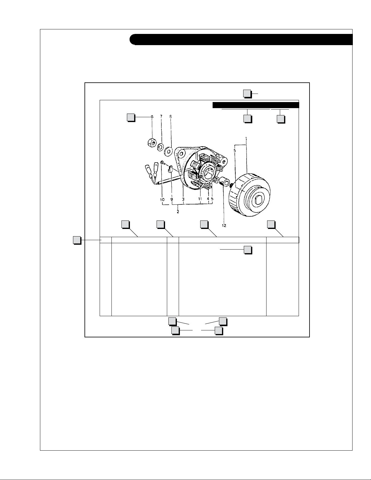
Reading a Parts Page
IMPORTANT:
Before selecting parts, be sure that you are choosing parts from the correct page.
Check the model designation at the page top.
Do not use this illustration for parts purchasing.
1
ELECTRICAL SYSTEM
ALTERNATOR ASSEMBLY: M - NL844
4
6
5
KEY PART NUMBER QTY. DESCRIPTION SERIALNUMBER
0 185046210 1 Alternator Assembly 1 185446219 1 Flywheel, complete 2 185446217 1 Plate, complete 3 185716200 1 Plate 4 185446218 1 Stator, complete 5 040126210 2 Bearing 6 020210010 1 Nut 7 027100010 1 Spring washer 8 026100010 1 Washer 9 185446220 1 Clamp 10 015140408 1 Screw 11 015140425 2 Screw 12 199236510 1 Collar -
7
8
10
3
2
9
13
11
P844 06/96
5 - 2
14
12
REFERENCES:
1. Grouping section title. 7. Quantity of parts used.
2. Model designation of equipment that uses parts 8. Description of each component part.
listedonthispage. 9. Serialnumberofunitthepartts.
3. Title and description of assembly. 10. Assembly or kit designated by Key 0 or ••/•.
4. Drawing numbers that correspond to key 11. Grouping index number.
columnnumbersforpartsidentication. 12. Pagenumberwithinthegroupingindex.
5. Key column for locating parts shown on drawing. 13. Manual title.
6. Part number. 14. Page publication date.
NOTE: a Arrows always point toward the front of the engine.
P6108 06/02
III
Page 6
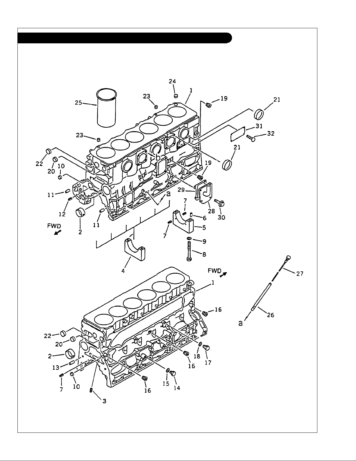
GROUP 1 - ENGINE
Cylinder Block L-M6108T-A-AQ
P6108 06/02
1 - 0
Figure 0201
Page 7
GROUP 1 - ENGINE
Cylinder Block L-M6108T-A-QA
KEY PART NUMBER QTY DESCRIPTION SERIAL NUMBER
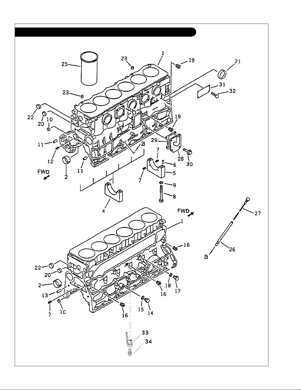
1 6222-21-1101 1 Cylinder Block Assembly (includes keys #2 - #24) 2 6221-21-1410 4 Camshaft Bushing 3 04025-00408 ** Spring Pin 4 6222-29-1210 6 Main Bearing Cap 5 6222-29-1250 1 Main Bearing Cap 6 04020-00514 2 Dowel Pin 7 04025-00408 6 Spring Pin 8 6221-21-1710 14 Bolt 9 6130-32-1361 14 Washer 10 07046-42216 2 Expansion Plug 11 6136-21-1911 2 Dowel Ring 12 04025-00512 1 Spring Pin 13 04020-01228 2 Dowel Pin 14 07040-11209 2 Plug 15 07005-01212 2 Gasket 16 07043-70108 3 Plug -
17 07040-11007 1 Plug 18 07005-01012 1 Gasket 19 07043-70211 2 Plug 20 07046-43016 2 Expansion Plug (064200030) 21 07046-46520 5 Expansion Plug 22 07046-43516 2 Expansion Plug 23 6221-21-1790 2 Bushing 24 07046-42010 1 Expansion Plug -
25 6222-23-2211 ** Cylinder Liner
6222-23-2221 ** Cylinder Liner
6222-23-2231 ** Cylinder Liner
26 6221-21-5410 1 Dipstick Tube
27 6206-21-5310 1 Dipstick
28 28-05701 1 Cover
6221-21-7210 1 Cover
(L-M) -
(NL) -
29 6136-21-7830 1 Gasket 30 01435-01025 4 Bolt 31 09605-01425 1 Name Plate
32 04418-02550 4 Screw -
***
See Dipstick & Tube for Heat Exchanged Units
(S) *
(M) *
(L) *
(Keel cooled Propulsion Units) *** -
(Keel cooled Propulsion Units) *** -
(limited supply) -
**As required
* *NOTE: For each cylinder, check that the mark on the
cylinder liner and the stamped mark (S, M or L)
on the top face of right side of the cylinder
block correctly coincide.
LINER MARK
BLOCK MARK LINER PART NO. Bottom Top
S 6222-23-2211 S I
M 6222-23-2221 M II
L 6222-23-2231 L III
P6108 06/02
1 - 1
Page 8
GROUP 1 - ENGINE
Cylinder Block L-M6108T2-A2
P6108 06/02
1 - 2
Figure 0201a
Page 9

GROUP 1 - ENGINE
Cylinder Block L-M6108T2-A2
KEY PART NUMBER QTY DESCRIPTION SERIAL NUMBER
1 6221-23-1120 1 Cylinder Block Assembly (includes keys #2 - #24) 2 6221-21-1410 4 Camshaft Bushing 4 6222-29-1210 6 Main Bearing Cap 5 6222-29-1250 1 Main Bearing Cap 6 04020-00514 2 Dowel Pin 7 04025-00408 6 Spring Pin 8 6221-21-1710 14 Bolt 9 6130-32-1361 14 Washer 10 07046-42216 2 Expansion Plug 11 6136-21-1911 2 Dowel Ring 12 04025-00512 1 Spring Pin 13 04020-01228 2 Dowel Pin 14 07040-11209 2 Plug 15 07005-01212 2 Gasket 16 07043-70108 3 Plug 17 07040-11007 1 Plug -
18 07005-01012 1 Gasket -
19 07043-70211 2 Plug -
20 07046-43016 2 Expansion Plug (064200030) -
21 07046-45016 3 Expansion Plug -
22 07046-43516 2 Expansion Plug -
23 6221-21-1790 2 Bushing -
25 6222-23-2211 ** Cylinder Liner
6222-23-2221 ** Cylinder Liner
6222-23-2231 ** Cylinder Liner
26 6221-21-5410 1 Dipstick Tube
27 6206-21-5310 1 Dipstick 28 28-05701 1 Cover
6221-21-7210 1 Cover
(L-M) -
(NL) -
29 6136-21-7830 1 Gasket 30 01435-01025 4 Bolt 31 09605-01425 1 Name Plate
32 04418-02550 1 Screw 33 6222-23-1810 6 Piston Cooling Nozzle 34 6222-23-1820 6 Check Valve -
(S) * -
(M) * -
(L) * -
(Keel Cooled) -
(limited supply) -
**As required
**NOTE: For each cylinder, check that the mark on the
cylinder liner and the stamped mark (S, M or L)
on the top face of right side of the cylinder
block correctly coincide.
LINER MARK
BLOCK MARK LINER PART NO. Bottom Top
S 6222-23-2211 S I
M 6222-23-2221 M II
L 6222-23-2231 L III
P6108 06/02
1 - 3
Page 10
GROUP 1 - ENGINE
Crankshaft Assembly
P6108 06/02
1 - 4
Figure 0231a
Page 11

GROUP 1 - ENGINE
Crankshaft Assembly
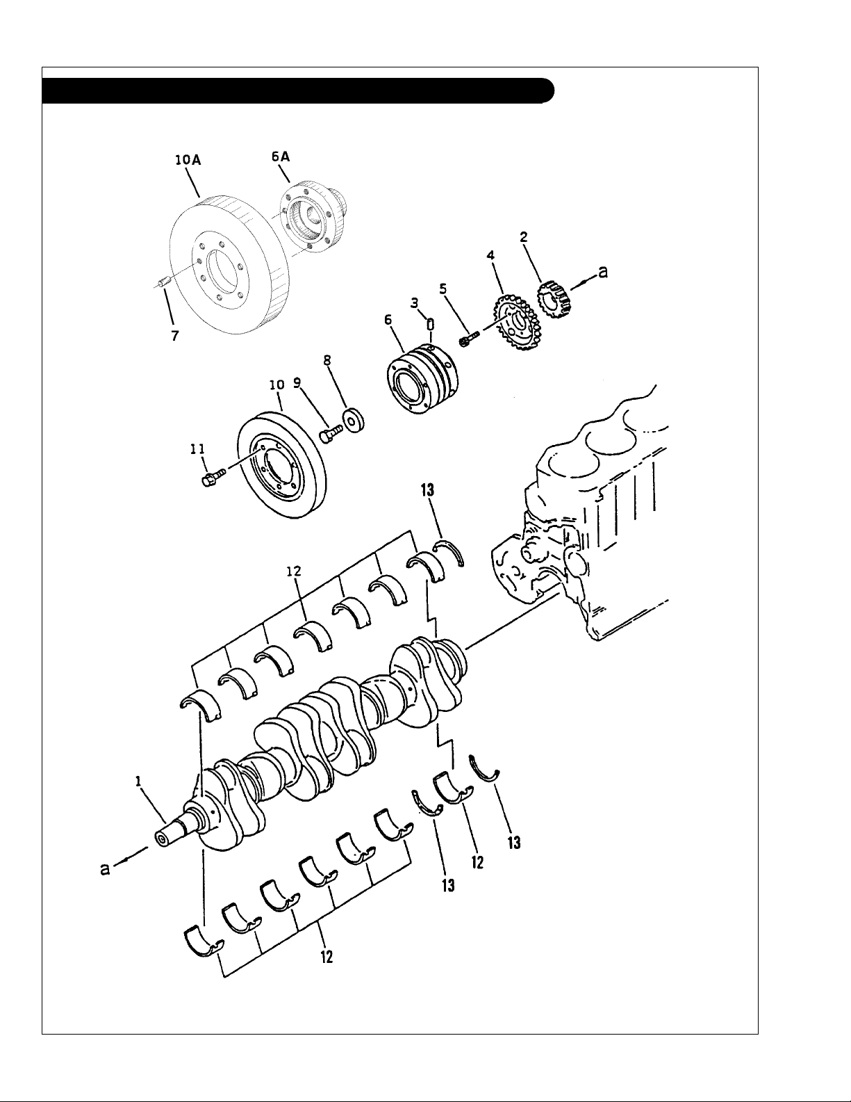
KEY PART NUMBER QTY DESCRIPTION KOMATSU S/N
1 6222-35-1900 1 Crankshaft Assembly (includes key #2) Up to - 17508
6222-35-1901 1 Crankshaft Assembly
2 6222-35-1920 1 Gear Up to - 17508
6222-35-1921 1 Gear From 17509 3 6138-31-1460 1 Pin From 12825 4 6222-35-1930 1 Gear, Oil Pump Drive 5 01252-30825 3 Bolt Up to - 17508
6136-31-1240 3 Bolt Up to - 22179
01437-00830 3 Bolt From 22180 6 6138-31-1452 1 Pulley (Early Production) Up to - 12824
6A 6222-35-1940 1 Adapter (Late Production) Up to - 17508
6222-35-1941 1 Adapter (Late Production) Up to - 22179
6222-35-1942 1 Adapter (Late Production) From 22180 7 04020-01228 1 Pin (used with #6A & #10A) From 12825 8 6136-31-1431 1 Plate 9 01050-31845 1 Bolt 10 6138-31-8100 1 Damper (Early Production) Up to - 12824
10A 6151-31-8300 1 Damper (Late Production) From 12825 11 01435-01220 6 Capscrew, Hex Head Flanged, M12 x 1.75 x 20 mm 12 6221-21-8010 7 Main Bearing Assembly, Std. 6221-29-8010 7 Main Bearing Assembly, undersize 0.25 mm 6221-28-8010 7 Main Bearing Assembly, undersize 0.50 mm 6221-27-8010 7 Main Bearing Assembly, undersize 0.75 mm 6221-26-8010 7 Main Bearing Assembly, undersize 1.00 mm 13 6221-21-8050 1 Thrust Bearing Assembly, Std. -
6221-29-8050 1 Thrust Bearing Assembly, oversize 0.25 mm -
6221-28-8050 1 Thrust Bearing Assembly, oversize 0.50 mm -
6221-27-8050 1 Thrust Bearing Assembly, oversize 0.75 mm -
6221-26-8050 1 Thrust Bearing Assembly, oversize 1.00 mm -
(includes key #2) From 17509 -
P6108 06/02
1 - 5
Page 12
GROUP 1 - ENGINE
Flywheel & Housing SAE #3/ #11-1/2 L6108
Figure 0221
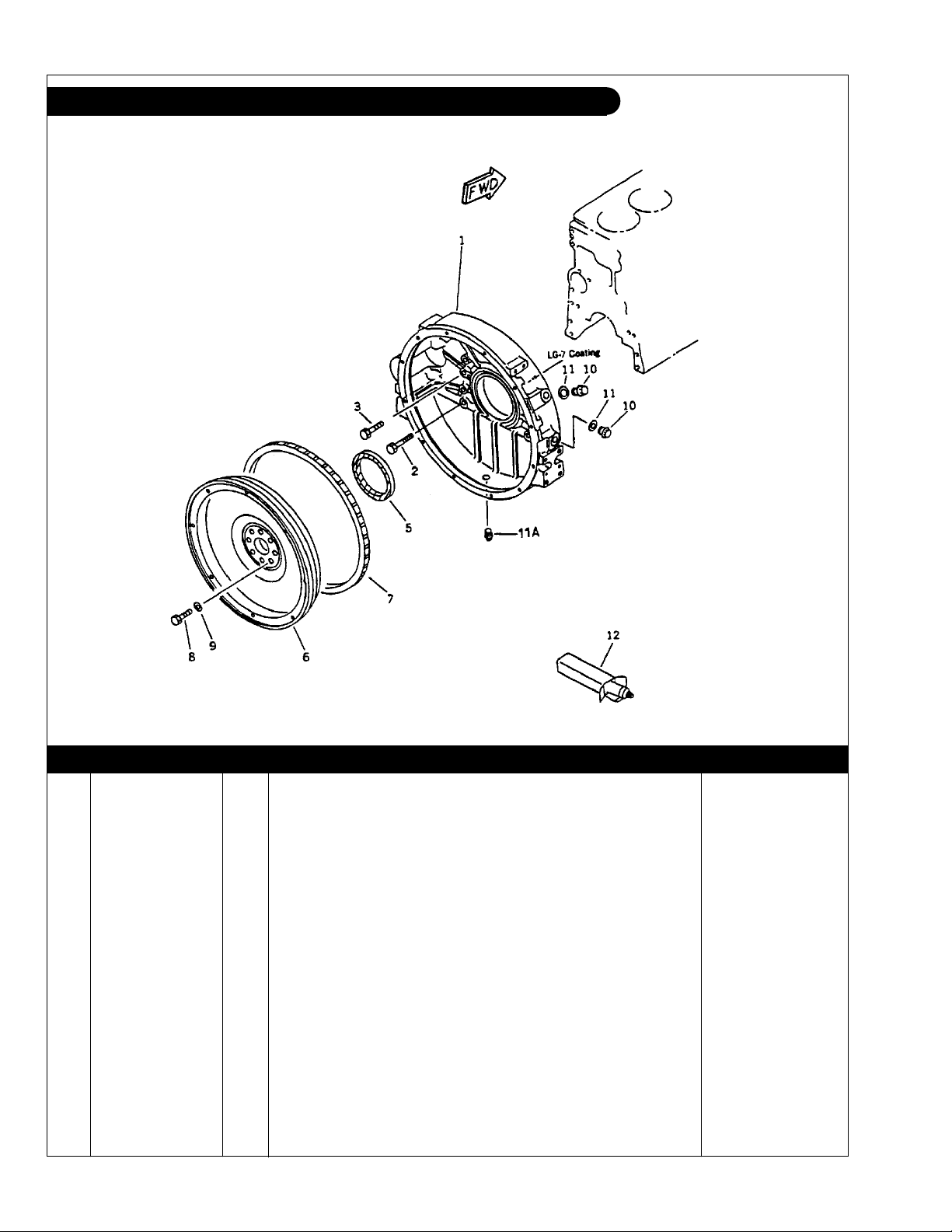
KEY PART NUMBER QTY DESCRIPTION SERIAL NUMBER
1 6221-21-4110 1 Flywheel Housing SAE#3 2 01435-01255 2 Capscrew, Hex Head Flanged, M12 x 1.75 x 55 mm,
3 01435-01245 9 Capscrew, Hex Head Flanged, M12 x 1.75 x 45 mm,
Grade 10.9 -
Grade 10.9 -
5 6221-21-4510 1 Rear Seal 6221-21-4520 1 Rear Main Seal (Repair Type) 6 31-65702 1 Flywheel Assembly SAE #11-1/2
7 6221-31-4190 1 Ring Gear
(122 Teeth) -
(includes key #7) -
8 01050-31435 8 Capscrew, Hex Head M14 x 1.5 x 35 mm 9 6130-32-1361 8 Flat Washer M14 Special 10 6114-11-8910 2 Plug 11 07005-02216 2 Gasket 11A 07042-00415 1 Plug 12 09920-00150 ** Liquid Gasket LG-7 -
**As required
P6108 06/02
1 - 6
Page 13
GROUP 1 - ENGINE
Flywheel & Housing SAE #1/ #14 L-M6108
Figure 0221 (ywheel6108)
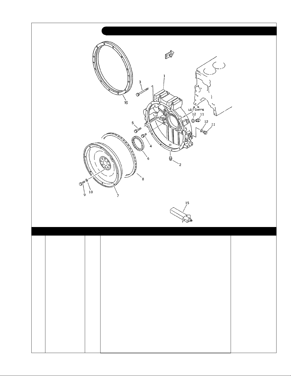
KEY PART NUMBER QTY DESCRIPTION SERIAL NUMBER
1 6222-21-4111 1 Flywheel Housing SAE#1 2 07042-00415 1 Plug 3 01436-01205 2 Capscrew, Hex Head Flanged M12 x 1.75 x 105 mm,
4 01435-01255 2 Capscrew, Hex Head Flanged M12 x 1.75 x 55 mm,
5 01435-01245 9 Capscrew, Hex Head Flanged M12 x 1.75 x 45 mm,
Grade 10.9 -
Grade 10.9 -
Grade 10.9 -
6 6221-21-4510 1 Rear Main Seal 6221-21-4520 1 Rear Main Seal
7 6221-31-4170 1 Flywheel Assembly SAE #14
8 6150-31-1351 1 Ring Gear
(Repair Type) -
(includes key #8) -
(148 Teeth) -
9 01050-31465 8 Capscrew, Hex Head M14 x 1.5 x 65 mm 10 6130-32-1361 8 Flat Washer M14 Special 11 6114-11-8910 2 Plug 12 07005-02216 2 Gasket 15 09920-00150 ** Liquid Gasket, LG-7 16 6221-21-4940 1 Adapter -
**As required
P6108 06/02
1 - 7
Page 14
GROUP 1 - ENGINE
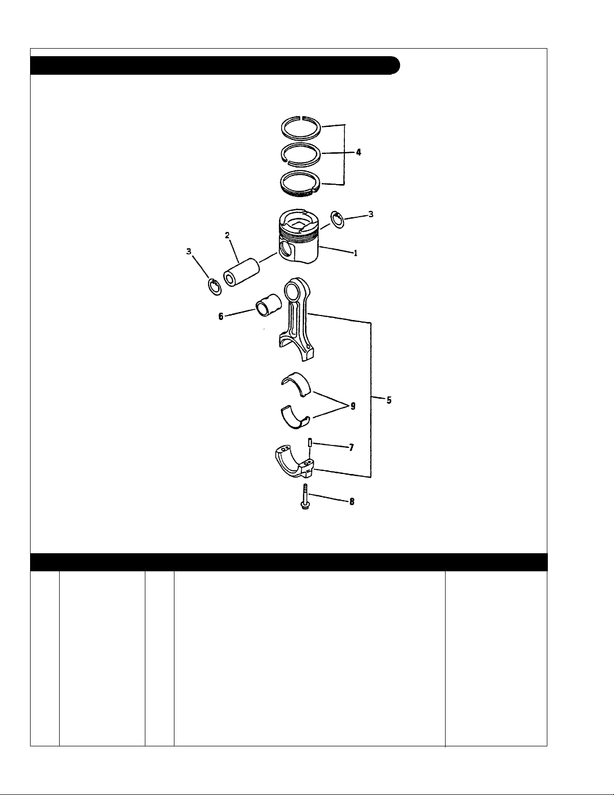
Piston & Connecting Rod L-M 6108T & A
Figure 0235
KEY PART NUMBER QTY DESCRIPTION SERIAL NUMBER
1 6222-31-2110 6 Piston 2 6221-31-2410 6 Piston Pin 3 04065-04518 12 Snap Ring 4 6221-31-2200 6 Piston Ring Set 5 6221-31-3100 6 Connecting Rod Assembly
6 6221-31-3130 1 Bushing 7 02400-10313 2 Dowel Pin 8 6221-31-3310 2 Bolt 9 6222-31-3040 6 Connecting Rod Bearing Assembly, Std. 6222-39-3040 6 Connecting Rod Bearing Assembly, undersize 0.25 mm 6222-38-3040 6 Connecting Rod Bearing Assembly, undersize 0.50 mm 6222-37-3040 6 Connecting Rod Bearing Assembly, undersize 0.75 mm 6222-36-3040 6 Connecting Rod Bearing Assembly, undersize 1.00 mm -
(includes keys #6 - #8) -
P6108 06/02
1 - 8
Page 15

GROUP 1 - ENGINE
Piston & Connecting Rod L-M 6108T2 & A2
Figure 0235
KEY PART NUMBER QTY DESCRIPTION SERIAL NUMBER
1 6222-35-2150 6 Piston 2 6221-31-2410 6 Piston Pin 3 04065-04518 12 Snap Ring 4 6221-31-2200 6 Piston Ring Set 5 6222-31-3100 6 Connecting Rod Assembly
6 6222-31-3130 1 Bushing 7 02400-10313 2 Dowel Pin 8 6221-31-3310 2 Bolt 9 6222-31-3050 6 Connecting Rod Bearing Assembly, Std. 6222-39-3050 6 Connecting Rod Bearing Assembly, undersize 0.25 mm 6222-38-3050 6 Connecting Rod Bearing Assembly, undersize 0.50 mm 6222-37-3050 6 Connecting Rod Bearing Assembly, undersize 0.75 mm 6222-36-3050 6 Connecting Rod Bearing Assembly, undersize 1.00 mm -
(includes keys #6 - #8) -
P6108 06/02
1 - 9
Page 16
GROUP 1 - ENGINE
Timing Cover L-M 6108
Without Accessory Drive
P6108 06/02
1 - 10
Figure 0205A
Page 17

GROUP 1 - ENGINE
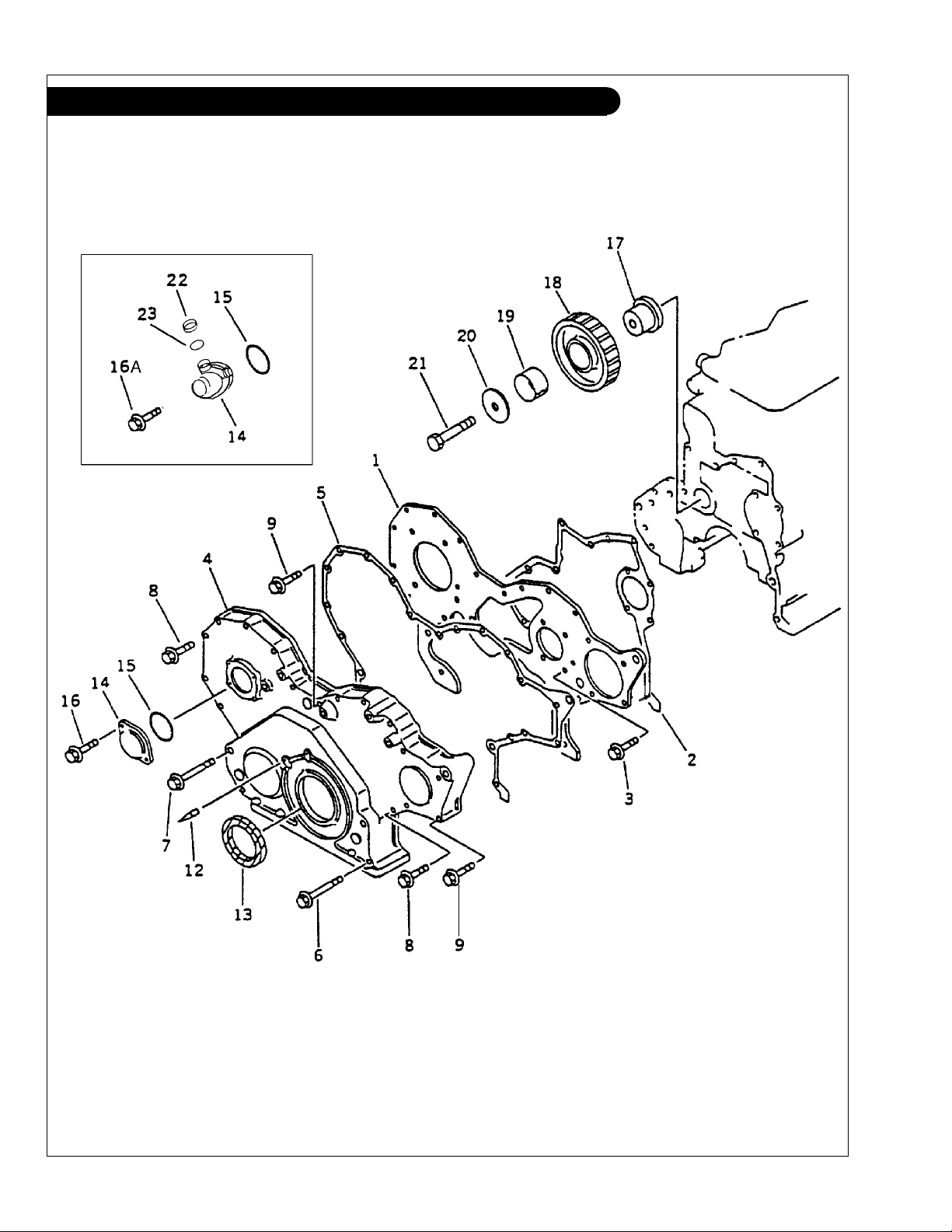
Timing Cover L-M 6108
Without Accessory Drive
KEY PART NUMBER QTY DESCRIPTION KOMATSU S/N
1 6222-21-3221 1 Cover Backing Plate Up to - 12824
2 6221-21-3820 1 Gasket
3 01435-00820 4 Capscrew, Hex Head Flanged M8 x 1.25 x 20 mm,
4 6221-21-3120 1 Timing Cover Up to - 12824
5 6221-21-3811 1 Gasket
6 01435-00885 2 Capscrew, Hex Head Flanged M8 x 1.25 x 85 mm,
7 01435-00895 2 Capscrew, Hex Head Flanged M8 x 1.25 x 95 mm,
8 01435-00855 8 Capscrew, Hex Head Flanged M8 x 1.25 x 55 mm,
9 01435-00865 4 Capscrew, Hex Head Flanged M8 x 1.25 x 65 mm,
12 6221-21-3910 1 Pin Up to - 12824
13 6136-22-3510 1 Front Seal
14 6144-81-5151 1 Cover Up to - 12824
6142-82-5112 1 Tachometer Drive 15 07000-03050 1 O-Ring Up to - 12824
16 01435-00612 2 Capscrew, Hex Head Flanged M6 x 1.0 x 12 mm,
16A 01435-00616 2 Capscrew, Hex Head Flanged M6 x 1.0 x 16 mm,
17 6221-21-2410 1 Idler Shaft Up to - 12824
18 6221-31-6300 1 Idler Gear Assembly
19 6221-31-6340 1 Bushing Up to - 12824
20 6221-21-2420 1 Washer Up to - 12824
21 01010-61480 1 Capscrew, Hex Head M14 x 2.0 x 80 mm Up to - 12824
22 6130-82-5260 1 Cap 23 6130-82-5270 1 Gasket -
(Formerly #6221-21-3890) Up to - 12824
Grade 10.9 Up to - 12824
(Formerly #6221-21-3810) Up to - 12824
Grade 10.9 Up to - 12824
Grade 10.9 Up to - 12824
Grade 10.9 Up to - 12824
Grade 10.9 Up to - 12824
(Formerly #6136-21-3510) Up to - 12824
Grade 10.9 Up to - 12824
Grade 10.9
(includes keys #19) Up to - 12824
P6108 06/02
1 - 11
Page 18
GROUP 1 - ENGINE
Timing Cover L-M 6108
With Accessory Drive
P6108 06/02
1 - 12
Figure 0205B
Page 19

GROUP 1 - ENGINE
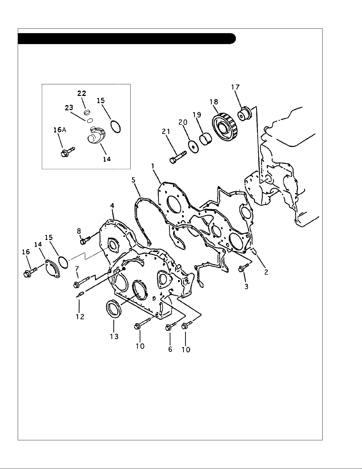
Timing Cover L-M 6108
With Accessory Drive
KEY PART NUMBER QTY DESCRIPTION KOMATSU S/N
1 6222-21-3221 1 Cover Backing Plate From 12825 2 6221-21-3820 1 Gasket
3 01435-00820 4 Capscrew, Hex Head Flanged M8 x 1.25 x 20 mm,
4 6222-25-3110 1 Timing Cover
5 6221-21-3811 1 Gasket
6 01435-00880 2 Capscrew, Hex Head Flanged M8 x 1.25 x 80 mm,
7 01436-00800 3 Capscrew, Hex Head Flanged M8 x 1.25 x 100 mm,
8 01435-00855 6 Capscrew, Hex Head Flanged M8 x 1.25 x 55 mm,
10 01435-00890 9 Capscrew, Hex Head Flanged M8 x 1.25 x 90 mm,
12 6221-21-3910 1 Pin
13 6136-22-3510 1 Front Seal
14 6144-81-5151 1 Cover
6142-82-5112 1 Tachometer Drive
15 07000-03050 1 O-Ring
16 01435-00612 2 Capscrew, Hex Head Flanged M6 x 1.0 x 12 mm,
16A 01435-00616 2 Capscrew, Hex Head Flanged M6 x 1.0 x 16 mm,
17 6221-21-2410 1 Idler Shaft
18 6221-31-6300 1 Idler Gear Assembly
19 6221-31-6340 1 Bushing
20 6221-21-2420 1 Washer
21 01010-61480 1 Capscrew, Hex Head M14 x 2.0 x 80 mm
22 6130-82-5260 1 Cap
23 6130-82-5270 1 Gasket
(Formerly #6221-21-3890)
Grade 10.9
(Formerly #6221-21-3810)
Grade 10.9
Grade 10.9
Grade 10.9
Grade 10.9
(Formerly #6136-21-3510)
Grade 10.9
Grade 10.9
(includes keys #19)
P6108 06/02
1 - 13
Page 20

GROUP 1 - ENGINE
Accessory Drive Assembly L-M6108
Figure 0208A
KEY PART NUMBER QTY DESCRIPTION SERIAL NUMBER
•• 6222-25-3401 1 Accessory Drive Assembly (includes keys 1 - 9) 1 6222-25-3411 1 Housing 2 6150-25-3422 1 Shaft 3 06030-05204 1 Bearing 4 04065-04718 1 Snap Ring 5 6222-25-3450 1 Gear
(23 Teeth) -
6 06030-06304 1 Bearing 7 07012-00035 1 Oil Seal 8 6222-25-3441 1 Hub -
9 07000-72060 1 O-Ring 10 01435-01035 3 Capscrew Hex Head Flanged M10 x 1.5 x 35 mm,
Grade 10.9 -
11 6222-25-3430 1 Pully 12 01435-00816 4 Capscrew Hex Head Flanged M8 x 1.25 x 16 mm,
Grade 10.9 -
13 6222-25-9330 1 Tube, Oil Supply 14 04434-50608 1 Clamp 15 01435-00816 1 Capscrew Hex Head Flanged M8 x 1.25 x 16 mm,
Grade 10.9 -
16 07206-30710 1 Banjo Bolt 17 07005-01012 2 Sealing Washer -
P6108 06/02
1 - 14
Page 21
GROUP 1 - ENGINE
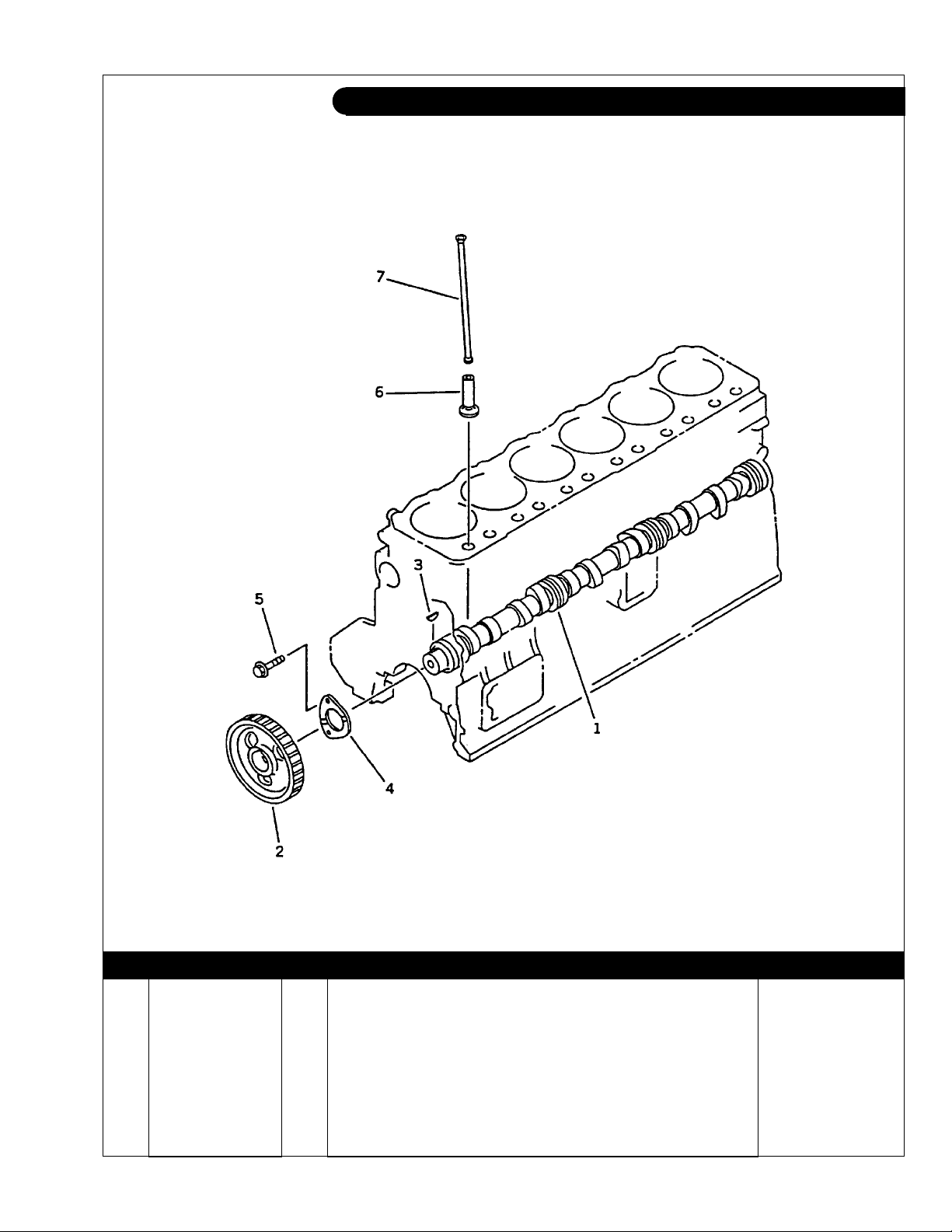
Camshaft L-M 6108
Figure 0241
KEY PART NUMBER QTY DESCRIPTION SERIAL NUMBER
•• 6221-41-1100 1 Camshaft Assembly (includes keys #1 - #4) 1 6221-41-1110 1 Camshaft 2 6221-41-1120 1 Gear 3 04010-00516 1 Key 4 6204-41-1131 1 Thrust Plate 5 01435-00820 2 Bolt 6 6221-41-2110 12 Tappet 7 6221-41-3110 12 Push Rod -
P6108 06/02
1 - 15
Page 22
GROUP 1 - ENGINE
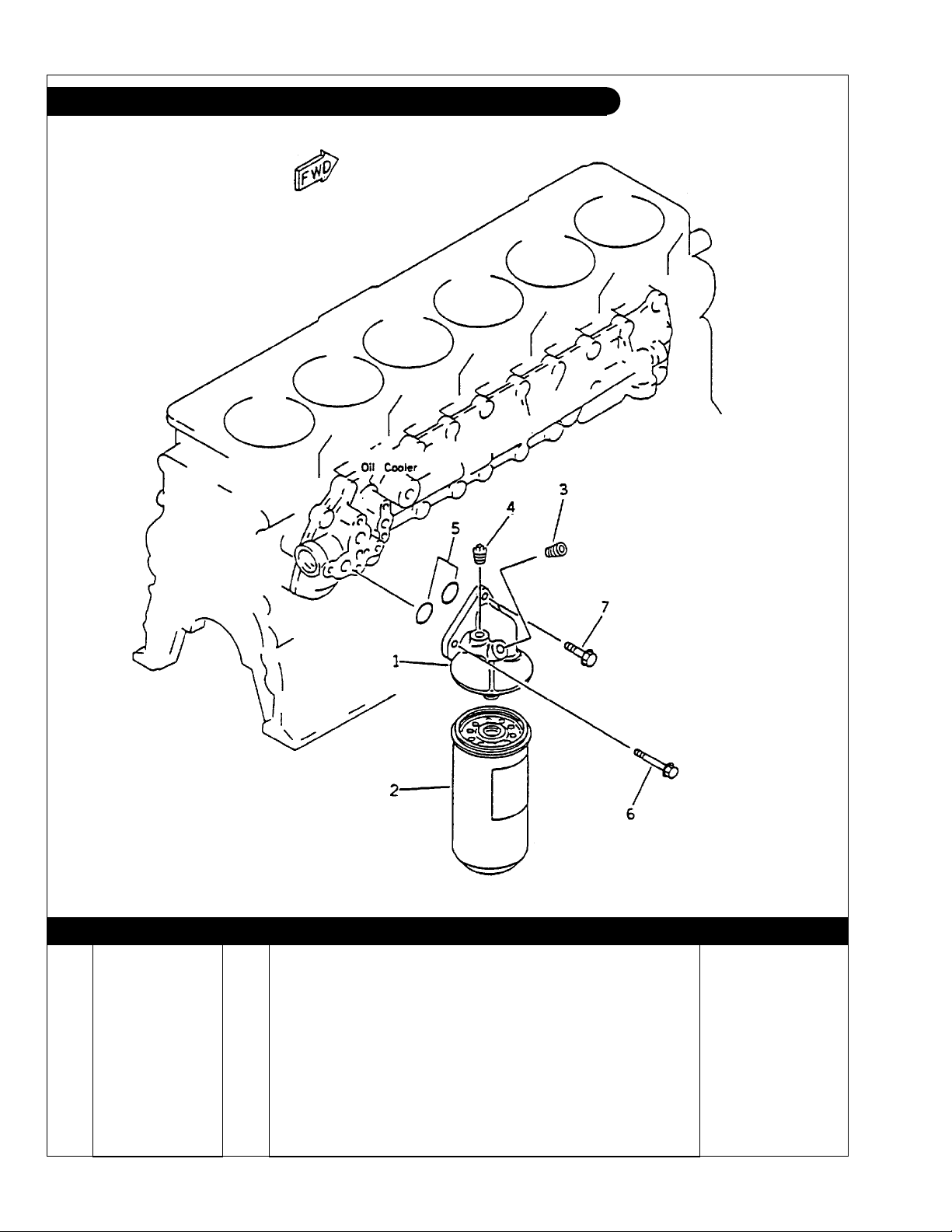
Oil Filter & Mounting L-M6108
Figure 0311
KEY PART NUMBER QTY DESCRIPTION SERIAL NUMBER
•• 6136-51-5102 1 Oil Filter Assembly (includes keys 1 - 3) 1 6136-51-5111 1 Bracket 2 24-05701 1 Oil Filter 3 07043-00108 ** Plug 4 07042-70108 ** Plug 5 07000-73028 2 O-Ring 6 01435-00885 1 Capscrew, Hex Head Flanged M8 x 1.25 x 85 mm,
7 01435-01030 2 Capscrew, Hex Head Flanged M10 x 1.5 x 30 mm,
**
As required
P6108 06/02
Grade 10.9 -
Grade 10.9 -
1 - 16
Page 23

GROUP 1 - ENGINE
Oil Pan L-M 6108
Figure 0211
KEY PART NUMBER QTY DESCRIPTION SERIAL NUMBER
1 36-75703 1 Oil Pan with Right Side Dipstick Tube 1 6136-21-5230 1 Oil Pan 2 36-75702 1 Bushing, M24 x 1.5 x 3/8 O-Ring Port 3 07000-13022 1 O-Ring
4 6136-21-5821 1 Gasket 5 01435-00816 38 Capscrew, Hex Head Flanged M8 x 1.25 x 16 mm,
6 36-75716 1 Dipstick, 0 Degree Down Angle 36-75723 1 Dipstick, 3 Degree Down Angle 36-75722 1 Dipstick, 5 Degree Down Angle 36-75726 1 Dipstick, 7 Degree Down Angle 36-75724 1 Dipstick, 10 Degree Down Angle -
(Can use 16-15004, formerly #07000-03022) -
Grade 10.9 -
P6108 06/02
1 - 17
Page 24
GROUP 1 - ENGINE
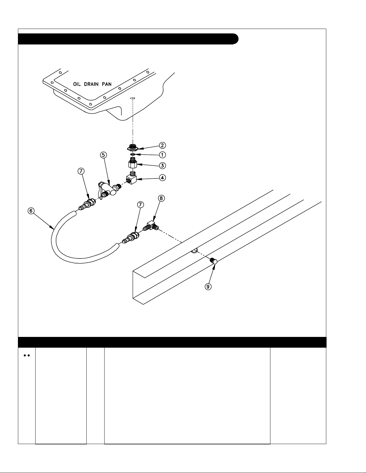
Oil Drain M-NL 6108
A-5870/ B-6498
KEY PART NUMBER QTY DESCRIPTION SERIAL NUMBER
36-75710 1 Oil Drain (includes all keys) 1 07000-03022 1 O-Ring 2 36-75702 1 Bushing, Stl. M24 x 1.5 x 3/8 OR Port 3 21-50001 1 Adapter, Stl. 3/8 NPT x 3/8 OR Port 4 21-51097 1 Elbow, 90 Degrees 3/8 NPT x 3/8 NPT 5 36-71002 1 Valve, Shut-Off, 3/8 NPT x 1/2-45T 6 18-71035 1 Hose, 1/2"ID x 18" 7 21-71042 1 Female Swivel Brass, 1/2 HB x 1/2-45T 8 21-01016 1 Male Elbow, 90 Degrees Brass, 1/2 NPT x 1/2-45T 9 21-10005 1 Plug, Hex Head, Stl. 1/2 NPT -
P6108 06/02
1 - 18
Page 25
GROUP 1 - ENGINE
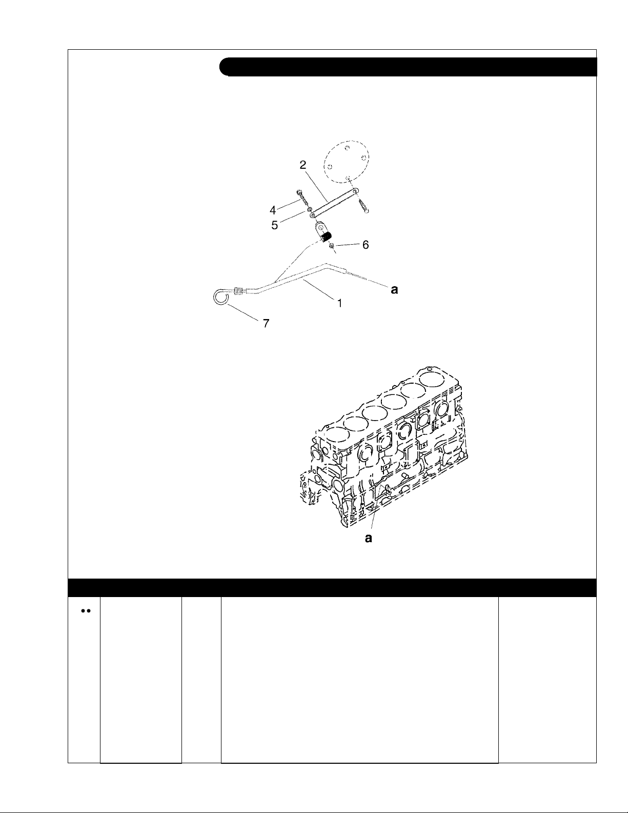
Dipstick L/M 6108
Heat Exchanged Units
6108dipstick
KEY PART NUMBER QTY DESCRIPTION SERIAL NUMBER
36-75706 1 Dipstick/ Tube Assembly 1 27-75703 1 Tube 2 23-75703 1 Bracket, Tube Support 3 19-53200 1 Adelle Clamp .50" I.D. 4 12-01131 1 Cap Screw, Hex Head M6 x 1.0 x 20 mm 5 15-00008 2 Flat Washer, M6 6 14-04803 1 Hex Nut, Nylock M6 x 1.0 7 36-75717 1 Dipstick Only -
P6108 06/02
1 - 19
Page 26
GROUP 1 - ENGINE
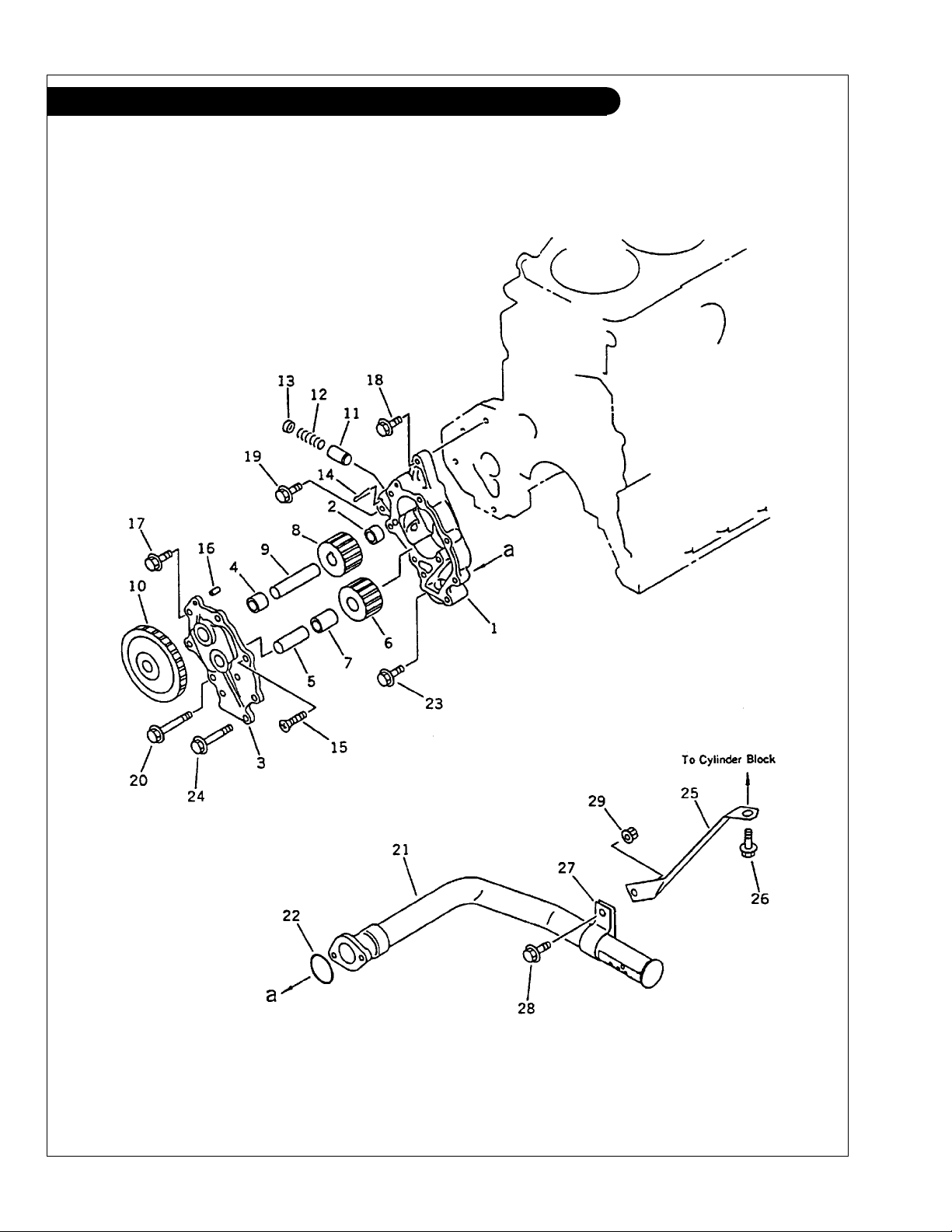
Oil Pump & Suction Pick-up L-M6108T-A-AQ
P6108 06/02
1 - 20
Figure 0301
Page 27

GROUP 1 - ENGINE
Oil Pump & Suction Pick-up L-M6108T-A-AQ
KEY PART NUMBER QTY DESCRIPTION SERIAL NUMBER
•• 6221-51-1100 1 Oil Pump Assembly (includes keys #1 - #17) 1 6222-55-1200 1 Body Assembly
2 6136-52-1220 1 Bushing 3 6221-51-1300 1 Cover Assembly
4 6136-52-1330 1 Bushing 5 6136-52-1320 1 Shaft -
•• 6136-52-1400 1 Gear Assembly
6 6136-52-1410 1 Gear 7 6136-52-1420 1 Bushing -
•• 6221-51-1500 1 Shaft Sub-Assembly
8 6136-52-1510 1 Gear 9 6221-51-1520 1 Shaft 10 6221-51-1610 1 Gear 11 6222-55-1640 1 Valve 12 6222-55-1650 1 Spring 13 6222-55-1660 1 Retainer 14 04050-14035 1 Cotter Pin 15 01236-40820 1 Screw 16 6136-52-1620 1 Pin 17 01435-00820 6 Capscrew, Hex Head, Flanged M8 x 1.25 x 20 mm
18 01435-00825 1 Capscrew, Hex Head, Flanged M8 x 1.25 x 25 mm
19 01435-00840 1 Capscrew, Hex Head, Flanged M8 x 1.25 x 40 mm
20 01435-00855 1 Capscrew, Hex Head, Flanged M8 x 1.25 x 55 mm
21 6221-51-6210 1 Oil Suction Pick-up 22 07000-73035 1 O-Ring 23 01435-00820 1 Capscrew, Hex Head, Flanged M8 x 1.25 x 20 mm
24 01435-00850 1 Capscrew, Hex Head, Flanged M8 x 1.25 x 50 mm
25 6221-51-6110 1 Bracket 26 01435-01020 1 Capscrew, Hex Head, Flanged M10 x 1.5 x 20 mm
27 6136-51-6230 1 Clamp 28 01435-00820 1 Capscrew, Hex Head, Flanged M8 x 1.25 x 20 mm
29 01584-00806 1 Nut -
(includes key #2) -
(includes keys #4 - #5) -
(includes keys #6 - #7) -
(includes keys #8 - #9) -
(Grade 10.9) -
(Grade 10.9) -
(Grade 10.9) -
(Grade 10.9) -
(Grade 10.9) -
(Grade 10.9) -
(Grade 10.9) -
(Grade 10.9) -
P6108 06/02
1 - 21
Page 28

GROUP 1 - ENGINE
Oil Pump & Suction Pick-up L-M6108T2-A2
P6108 06/02
1 - 22
Figure 0301
Page 29

GROUP 1 - ENGINE
Oil Pump & Suction Pick-up L-M6108T2-A2
KEY PART NUMBER QTY DESCRIPTION SERIAL NUMBER
•• 6222-55-1100 1 Oil Pump Assembly (includes keys #1 - #17) 1 6221-55-1200 1 Body Assembly
2 6136-52-1220 1 Bushing 3 6221-51-1300 1 Cover Assembly
4 6136-52-1330 1 Bushing 5 6136-52-1320 1 Shaft -
•• 6136-52-1400 1 Gear Assembly
6 6136-52-1410 1 Gear 7 6136-52-1420 1 Bushing -
•• 6221-51-1500 1 Shaft Sub-Assembly
8 6136-52-1510 1 Gear 9 6221-51-1520 1 Shaft 10 6221-51-1610 1 Gear 11 6222-55-1640 1 Valve 12 6222-55-1650 1 Spring 13 6222-55-1660 1 Retainer 14 04050-14035 1 Cotter Pin 15 01236-40820 1 Screw 16 6136-52-1620 1 Pin 17 01435-00820 6 Capscrew, Hex Head, Flanged M8 x 1.25 x 20 mm
18 01435-00825 1 Capscrew, Hex Head, Flanged M8 x 1.25 x 25 mm
19 01435-00840 1 Capscrew, Hex Head, Flanged M8 x 1.25 x 40 mm
20 01435-00855 1 Capscrew, Hex Head, Flanged M8 x 1.25 x 55 mm
21 6221-51-6210 1 Oil Suction Pick-up 22 07000-73035 1 O-Ring 23 01435-00820 1 Capscrew, Hex Head, Flanged M8 x 1.25 x 20 mm
24 01435-00850 1 Capscrew, Hex Head, Flanged M8 x 1.25 x 50 mm
25 6221-51-6110 1 Bracket 26 01435-01020 1 Capscrew, Hex Head, Flanged M10 x 1.5 x 20 mm
27 6136-51-6230 1 Clamp 28 01435-00820 1 Capscrew, Hex Head, Flanged M8 x 1.25 x 20 mm
29 01584-00806 1 Nut -
(includes key #2) -
(includes keys #4 - #5) -
(includes keys #6 - #7) -
(includes keys #8 - #9) -
(Grade 10.9) -
(Grade 10.9) -
(Grade 10.9) -
(Grade 10.9) -
(Grade 10.9) -
(Grade 10.9) -
(Grade 10.9) -
(Grade 10.9) -
P6108 06/02
1 - 23
Page 30
GROUP 1 - ENGINE
Cylinder Head & Valve Train L-M6108T-A-QA
P6108 06/02
1 - 24
Figure 0101& 0111
Page 31

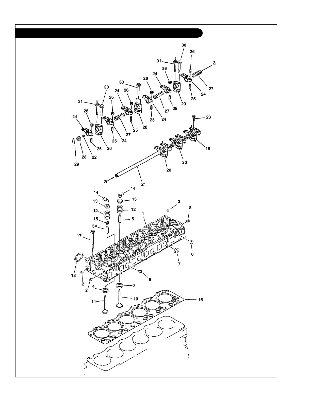
GROUP 1 - ENGINE
Cylinder Head & Valve Train L-M6108T-A-QA
KEY PART NUMBER QTY DESCRIPTION SERIAL NUMBER
1 6221-11-1102 1 Cylinder Head Assembly (former #6221-11-1100, includes keys #2 -#9) -
2 07046-41810 8 Plug 3 6221-13-1360 6 Intake Valve Seat -Std. 6221-19-1360 6 Intake Valve Seat, oversize 0.25 mm 6221-18-1360 6 Intake Valve Seat, oversize 0.50 mm 6221-17-1360 6 Intake Valve Seat, oversize 0.75 mm 6221-16-1360 6 Intake Valve Seat, oversize 1.00 mm 4 6221-11-1320 6 Exhaust Valve Seat - Std. 6221-19-1320 6 Exhaust Valve Seat, oversize 0.25 mm 6221-18-1320 6 Exhaust Valve Seat, oversize 0.50 mm 6221-17-1320 6 Exhaust Valve Seat, oversize 0.75 mm 6221-16-1320 6 Exhaust Valve Seat, oversize 1.00 mm 5 6221-19-1311 6 Intake Valve Guide 5A 6221-19-1340 6 Exhaust Valve Guide 6 07046-42816 17 Plug 7 07046-44016 4 Plug 8 07043-70108 1 Plug 9 07043-70108 6 Plug 10 6221-41-4110 6 Intake Valve 11 6221-41-4211 6 Exhaust Valve 12 6221-41-4410 12 Spring Valve 13 6221-41-4510 12 Spring Retainer 14 6136-42-4520 24 Valve Keeper 15 6140-41-4540 6 Exhaust Valve Guide Seal -
16 6221-17-1810 1 Head Gasket,
17 6221-11-1610 26 Head Bolt 18 6221-11-6820 1 Gasket 6221-41-5101 1 Rocker Arm Assembly
19 6221-41-5120 1 Rocker Arm Stand 20 6221-41-5110 5 Rocker Arm Stand 21 6221-41-5201 1 Shaft Assembly
22 6221-41-5540 2 Plug 23 6221-41-5310 1 Bolt 24 6221-41-5510 12 Rocker Arm 25 6221-41-5410 12 Adjusting Screw 26 6221-41-5420 12 Nut 27 6221-41-5550 5 Spring 28 6221-41-5520 2 Spring 29 6136-41-5330 2 Clip 30 01435-00875 8 Capscrew, Hex Head Flanged, M8 x 1.25 x 75 mm
31 6221-41-5130 4 Bolt -
(formerly #6221-11-1811) -
(includes keys #19 - 29) -
(includes key 22) -
(Grade 10.9) -
P6108 06/02
1 - 25
Page 32

GROUP 1 - ENGINE
Cylinder Head & Valve Train L-M6108T2-A2
P6108 06/02
1 - 26
Figure 0101& 0111
Page 33

GROUP 1 - ENGINE
Cylinder Head & Valve Train L-M6108T2-A2
KEY PART NUMBER QTY DESCRIPTION SERIAL NUMBER
1 6222-15-1100 1 Cylinder Head Assembly 2 07046-41810 8 Plug 3 6221-13-1360 6 Intake Valve Seat -Std. 6221-19-1360 6 Intake Valve Seat, oversize 0.25 mm 6221-18-1360 6 Intake Valve Seat, oversize 0.50 mm 6221-17-1360 6 Intake Valve Seat, oversize 0.75 mm 6221-16-1360 6 Intake Valve Seat, oversize 1.00 mm 4 6221-11-1320 6 Exhaust Valve Seat - Std. 6221-19-1320 6 Exhaust Valve Seat, oversize 0.25 mm 6221-18-1320 6 Exhaust Valve Seat, oversize 0.50 mm 6221-17-1320 6 Exhaust Valve Seat, oversize 0.75 mm 6221-16-1320 6 Exhaust Valve Seat, oversize 1.00 mm 5 6221-19-1311 12 Valve Guide 6 07046-42816 17 Plug 7 07046-44016 4 Plug 8 07043-70108 1 Plug 9 07043-70108 6 Plug 10 6221-41-4110 6 Intake Valve 11 6221-41-4220 6 Exhaust Valve 12 6221-41-4410 12 Spring Valve 13 6221-41-4510 12 Spring Retainer 14 6136-42-4520 24 Valve Keeper 15 6140-41-4540 6 Exhaust Valve Guide Seal 16 6221-17-1810 1 Head Gasket -
17 6221-11-1610 26 Head Bolt -
18 6221-11-6820 1 Gasket -
•• 6221-41-5101 1 Rocker Arm Assembly
19 6221-41-5120 1 Rocker Arm Stand 20 6221-41-5110 5 Rocker Arm Stand 21 6221-41-5201 1 Shaft Assembly
22 6221-41-5540 2 Plug 23 6221-41-5310 1 Bolt 24 6221-41-5510 12 Rocker Arm 25 6221-41-5410 12 Adjusting Screw 26 6221-41-5420 12 Nut 27 6221-41-5550 5 Spring 28 6221-41-5520 2 Spring 29 6136-41-5330 2 Clip 30 01435-00875 8 Capscrew, Hex Head Flanged, M8 x 1.25 x 75 mm
31 6221-41-5130 4 Bolt -
(includes keys #19 - 29) -
(includes key 22) -
(Grade 10.9) -
P6108 06/02
1 - 27
Page 34

GROUP 1 - ENGINE
Rocker Arm Cover L-M6108
A-5244 / C-2629
KEY PART NUMBER QTY DESCRIPTION SERIAL NUMBER
1 10-75700 1 Rocker Arm Cover 2 6136-11-8814 1 Gasket 3 6130-12-8610 1 Oil Filler Cap 4 1 Crank Case Vent Tube - Lugger
5 14-75700 4 Blind Hex Nut, M8 x 1.25 x 35 6 6136-11-8130 4 Washer 7 6136-11-8142 4 Packing 8 16-15704 1 O-Ring -
P6108 06/02
(see Air Filter Parts Detail) -
1 - 28
Page 35

GROUP 1 - ENGINE
Rocker Arm Cover LC6108
Figure 0115
KEY PART NUMBER QTY DESCRIPTION SERIAL NUMBER
1 6136-11-8112 1 Rocker Arm Cover 2 6136-11-8814 1 O-ring 3 6136-11-8120 4 Blind Hex Nut, M8 x 1.25 x 10 mm 4 6136-11-8130 4 Washer 5 6136-11-8142 4 Packing 6 6130-12-8610 1 Cap 7 6150-21-6750 1 Breather 8 6114-21-5190 1 O-ring -
P6108 06/02
1 - 29
Page 36

GROUP 2 - INTAKE & EXHAUST SYSTEM
Lower Intake Manifold & Aftercooler L-M6108
Figure 0131
KEY PART NUMBER QTY DESCRIPTION SERIAL NUMBER
1 6222-11-4110 1 Intake Manifold, Lower Half 2 6222-15-4710 1 Gasket
(formerly #6222-11-4710) -
3 6222-61-6111 1 Aftercooler Element 4 6222-61-6240 4 O-Ring 5 01435-20830 2 Capscrew, Hex Head Flanged, M8 x 1.25 x 30 mm 6 6138-61-6461 1 Gasket 7 6222-61-6420 1 Tube 8 6221-11-4890 6 Gasket 9 6222-11-4910 11 Capscrew, Hex Head Flanged, M8 x 1.25 x 125 mm
(Grade 10.9) -
10 6222-11-4920 1 Bolt 11 01435-00875 5 Capscrew, Hex Head Flanged, M8 x 1.25 x 75 mm
(Grade 10.9) -
12 01435-20820 2 Capscrew, Hex Head Flanged, M8 x 1.25 x 20 mm 13 01435-00890 1 Capscrew, Hex Head Flanged, M8 x 1.25 x 90 mm
(Grade 10.9) -
14 6221-71-5980 1 Bracket 15 6131-71-5760 1 Spacer 16 07043-70108 2 Plug 17 6222-61-6480 1 O-Ring 18 6222-61-6410 1 Connector 19 6222-11-6880 2 Gasket -
P6108 06/02
2 - 0
Page 37

GROUP 2 - INTAKE & EXHAUST SYSTEM
Intake Manifold - Upper Half L-M6108
A-5207 / D-2184
KEY PART NUMBER QTY DESCRIPTION SERIAL NUMBER
1 10-25703 1 Aftercooler Cover 2 1 Air Inlet Connector
(see applicable Turbocharger Assembly) -
3 11-25701 1 Gasket 4 27-15705 1 Tube, Aftercooler Outlet 5 6222-11-6810 1 Gasket 6 145536340 1 Hose 7 28-15701 1 Plate
00-75721 1 Plate (Late Production) -
8 6222-15-4710 1 Gasket
(Early Production - use 00-75721 & 27-15721) -
(formerly #6222-11-4710) -
11-25702 1 Gasket 9 19-00016 2 Hose Clamp #16 10 6221-11-6890 1 Gasket 11 21-71049 2 Male Elbow, 90° Steel 1/4 NPT x 1/4-37T 12 27-15707 1 Tube Assembly
27-15721 1 Tube Assembly (Late Production) -
(Early Production - use 27-15721 & 00-75721) -
13 12-00710 24 Capscrew, Hex Head M8 x 1.25 x 90mm 14 12-00071 2 Capscrew, Hex Head M10 x 1.5 x 70mm 15 01140-61025 2 Stud, M10 x 1.25 x 25 mm
(32 mm LOA) * -
16 12-00831 2 Capscrew, Hex Head M10 x 1.5 x 25mm 17 12-00753 2 Capscrew, Hex Head M8 x 1.25 x 30mm 18 15-00701 24 Flat Washer, M8 19 15-00805 4 Flat Washer, M10 20 15-00802 2 Lock Washer, Helical M10 21 15-00702 2 Lock Washer, Helical M8 22 14-00816 2 Hex Nut M10 x 1.25 * 23 6222-61-6460 1 Connector 24 07062-00000 1 Drain Cock 1/8 NPT 25 6222-61-6111 1 Aftercooler Element
*
Former stud #15 & nut #22 replaced by items listed. Replace together.
P6108 06/02
2 - 1
Page 38

GROUP 2 - INTAKE & EXHAUST SYSTEM
Air Filter & Mounting L-LC6108A SAE #3
A-6739, A-5512/ B-6590
KEY PART NUMBER QTY DESCRIPTION SERIAL NUMBER
1 24-25701 1 Air Filter (includes key #11) -
2 31-25701 1 Adapter, Filter & Breather Connection L6108 31-25702 1 Adapter, Filter Connection, LC6108 3 23-05701 1 Bracket, Filter & Relay Mounting 4 24-25702 1 Filter Sleeve 5 19-00048 2 Hose Clamp #48 6 18-25702 1 Hose, 3" x 2-3/4" 7 19-00008 2 Hose Clamp #8, L6108 8 18-11010 1 Hose, 3/4" x 4-1/4", L6108 9 12-00911 2 CS, Hex Head M12 x 1.75 x 20mm 10 15-00912 2 Lock Washer, Helical M12 11 19-00048 1 Hose Clamp #48 12 27-75701 1 Tube, Crank Case Vent -
*Note: Keys 7, 8, & 12 are not used on LC6108
P6108 06/02
2 - 2
Page 39

GROUP 2 - INTAKE & EXHAUST SYSTEM
Air Filter & Mounting L6108A SAE #1
A-5850/ B-6597
KEY PART NUMBER QTY DESCRIPTION SERIAL NUMBER
1 24-25701 1 Air Filter (includes key #11) -
2 31-25701 1 Adapter, Filter & Breather Connection 3 23-25702 1 Bracket, Filter Mounting 4 24-25702 1 Filter Sleeve 5 19-00048 2 Hose Clamp #48 6 18-25702 1 Hose, 3" x 2-3/4" 7 19-00008 2 Hose Clamp #8, L6108 8 18-11010 1 Hose, 3/4" ID x 4-1/4", L6108 9 12-00922 2 Capscrew, Hex Head M12 x 1.75 x 90 mm 10 15-00912 2 Lock Washer, Helical M12 11 19-00048 1 Hose Clamp #48 12 27-75701 1 Tube, Crank Case Vent -
P6108 06/02
2 - 3
Page 40

GROUP 2 - INTAKE & EXHAUST SYSTEM
Cleanable Air Filter/Sleeve & Mounting L6108A2 SAE #3
A-7417/ B-6529
KEY PART NUMBER QTY DESCRIPTION SERIAL NUMBER
1 24-25701 1 Air Filter Element 2 31-25702 1 Adapter, Air Filter Mounting 3 23-05701 1 Bracket, Filter & Circuit Breaker Mounting 4 24-25702 1 Air Filter Sleeve 5 19-00048 1 Hose Clamp #48 6 18-25704 1 Hump Hose, 4" x 3" x 5" LOA (with vent) 7 19-00072 1 Hose Clamp #72 8 27-25703 1 Crankcase Vent Tube 9 12-00911 2 Capscrew, Hex Head M12 x 1.75 x 20 mm 10 15-00912 2 Lock Washer, Helical M12 11 19-00048 1 Hose Clamp #48 12 15-00111 2 Flat Washer 1/4" 13 15-00702 2 Lock Washer, Helical M8 14 12-00751 2 Capscrew, Hex Head M8 x 1.25 x 16 mm -
P6108 06/02
2 - 4
Page 41

GROUP 2 - INTAKE & EXHAUST SYSTEM
Cleanable Air Filter/Sleeve & Mounting L6108A2 SAE #1
A-7441/ B-6596
KEY PART NUMBER QTY DESCRIPTION SERIAL NUMBER
1 24-25701 1 Air Filter Element 2 31-25702 1 Adapter, Air Filter Mounting 3 23-25702 1 Bracket, Filter Mounting 4 24-25702 1 Air Filter Sleeve 5 19-00048 1 Hose Clamp #48 6 18-25704 1 Hump Hose, 4" x 3" x 5" LOA (with vent) 7 19-00072 1 Hose Clamp #72 8 27-25703 1 Crankcase Vent Tube 9 12-00912 2 Capscrew, Hex Head M12 x 1.75 x 25 mm 10 15-00912 2 Lock Washer, Helical M12 11 19-00048 1 Hose Clamp #48 -
P6108 06/02
2 - 5
Page 42

GROUP 2 - INTAKE & EXHAUST SYSTEM
Disposable Air Filter & Mounting L6108A2 SAE #3
A-8787/ C-4669
KEY PART NUMBER QTY DESCRIPTION SERIAL NUMBER
1 24-25706 1 Air Filter Element 2 23-05703 1 Bracket, Air Filter Mounting 3 12-00911 2 Capscrew, Hex Head M12 x 1.75 x 20 mm 4 15-00912 2 Lock Washer, Helical M12 5 27-25705 1 Tube, Air Inlet 4" OD
6 18-25706 1 Hose, 4" ID x 2" 7 19-00072 3 Hose Clamp #72 8 27-25706 1 Crankcase Vent Tube 9 18-11010 1 Hose 3/4" ID x 4-1/4" 10 19-00008 2 Hose Clamp #8 -
(with 3/4 HB Breather Connection) -
P6108 06/02
2 - 6
Page 43

GROUP 2 - INTAKE & EXHAUST SYSTEM
Disposable Air Filter & Mounting L6108A2 SAE #1
A-8787/ C-4396
KEY PART NUMBER QTY DESCRIPTION SERIAL NUMBER
1 24-25706 1 Air Filter Element 2 23-25706 1 Bracket, Air Filter Mounting 3 12-00912 2 Capscrew, Hex Head M12 x 1.75 x 25 mm 4 15-00912 2 Lock Washer, Helical M12 5 27-25705 1 Tube, Air Inlet 4" OD
6 18-25706 1 Hose, 4" ID x 2" 7 19-00072 3 Hose Clamp #72 8 27-25706 1 Crankcase Vent Tube 9 18-11010 1 Hose 3/4" ID x 4-1/4" 10 19-00008 2 Hose Clamp #8 11 15-00007 2 Flat Washer M12 -
(with 3/4 HB Breather Connection) -
P6108 06/02
2 - 7
Page 44

GROUP 2 - INTAKE & EXHAUST SYSTEM
Air Filter and Mounting M6108
A-5946/ C-2641A
KEY PART NUMBER QTY DESCRIPTION SERIAL NUMBER
1 24-21000 1 Air Filter 2 18-21004 1 Hump Hose 4" x 2" x 4-3/4" LOA
18-21003 1 Hump Hose 4" x 2-3/4" x 4" LOA
3 23-25703 1 Bracket, Air Filter Support
23-25704 1 Bracket, Air Filter Support
(K26 Turbo)* -
(K27 Turbo)* -
(K26 Turbo)* -
(K27 Turbo)* -
4 19-00128 1 Hose Clamp #128 5 19-00072 1 Hose Clamp #72 6 19-00036 1 Hose Clamp #36
19-00044 1 Hose Clamp #44
(K26 Turbo) -
(K27 Turbo) -
7 12-00912 2 Capscrew, Hex Head M12 x 1.75 x 25 mm 8 15-00912 2 Lock Washer, Helical M12 9 27-25702 1 Crankcase Vent Tube 10 18-11010 1 Hose, 3/4" ID x 4-1/4" 11 19-00008 2 Hose Clamp #8 12 21-00025 1 M. Elbow, 90
*
Bracket selection
See Turbocharger Application Chart to verify Hump Hose and
0
, PVC 3/4 HB x 3/4 HB -
P6108 06/02
2 - 8
Page 45

GROUP 2 - INTAKE & EXHAUST SYSTEM
Exhaust Manifold L-M6108
A-6651, A-6652, A5199 / D-2181A
KEY PART NUMBER QTY DESCRIPTION SERIAL NUMBER
1 10-35701 1 Exhaust Manifold (Schwitzer S-3A Turbo) L6108 (includes keys 8-11)* -
10-35702 1 Exhaust Manifold (K26 Turbo) M6108
10-35703 1 Exhaust Manifold (K27 & K31 Turbos) L-M6108
(includes keys 8-11)* -
(includes keys 8-11)* -
2 11-35705 1 Exhaust Manifold Gasket 3 11-35700 4 Exhaust Manifold Gasket 4 12-35701 12 Capscrew, Hex Head M10 x 1.5 x 120 mm
Grade 10.9 -
5 15-00802 12 Lock Washer, Helical M10 6 10-15703 1 Exhaust Manifold Connector
(includes keys 11-13) -
7 16-15007 2 O-Ring 8 17-14802 1 Expansion Plug 2"
9 17-10054 3 Expansion Plug 1-1/4"
10 21-51098 1 Street Elbow, 90
(not shown) -
(not shown) -
0
Brass 1/4 NPT 11 21-10002 2 Drain Cock, Brass 1/4 NPT 12 21-31003 1 Plug, Hex Head, Brass 3/8 NPT 13 21-00530 1 Plug, Hex Head, Brass 1/2 NPT -
*Note:
selection.
See Turbocharger Application Chart to verify Exhaust Manifold
P6108 06/02
2 - 9
Page 46

GROUP 2 - INTAKE & EXHAUST SYSTEM
Turbocharger Application List
Propulsion Engines
Pre-Emissions Compliant, year 1999 and older
Part Number
30-35701 S-3AW080 Schwitzer/ Borg-Warner, 3" Air Inlet (ID Tag # 199207)
L6108A to 350 Hp
L6108A2 @ 270 Hp
LC6108A All Ratings
30-35702 S-3ALW-155 Schwitzer/ Borg-Warner, 4" Inlet (ID Tag # 168859)
L6108A2 to 410 Hp
Description
Propulsion Engines
Emissions Compliant, year 2000 and newer
Part Number
30-35703 K31 KKK/ Borg-Warner, 4 -1/8" Air Inlet (Compresser Housing
Casting # 5328 101 50 85)
L6108A2 to 410 Hp
Description
Note: Also supplied in retrot assemblies on earlier L6108A2 @ 410 Hp
Generator Drive Engines
Emissions Compliant, year 2000 and newer
DescriptionPart Number
30-31627-1 K27 KKK/ Borg-Warner, 2 -3/4" Air Inlet (ID Tag #5327 970 70 90 or
5327 988 70 90)
M6108A2 150 kW @ 1800 RPM
M6108T2 125 kW @ 1800 RPM
P6108 06/02
2 - 10
Page 47

GROUP 2 - INTAKE & EXHAUST SYSTEM
Turbocharger Application List
Generator Drive Engines
Pre-Emissions Compliant, year 1999 and older
Part Number
30-31426-1 K26 KKK/ Borg-Warner, 2" Air Inlet (ID Tag #5326 970 64 93 or
5326 988 64 93)
M6108A 150 kW @ 1800 RPM
M6108A 125 kW @ 1500 RPM
M6108T 125 kW @ 1800 RPM
M6108T 104 kW @ 1500 RPM
M6108A2 125 kW @ 1500 RPM
Description
Generator Drive Engines
Part Number
30-31426-1 K26 KKK/ Borg-Warner, 2" Air Inlet (ID Tag #5326 970 64 93 or
5326 988 64 93)
M6108A2 125 kW @ 1500 RPM
Emissions Compliant, year 2000 and newer
Description
Generator Drive Engines
No Emissions Compliance Required
Part Number
30-31426-1 K26 KKK/ Borg-Warner, 2" Air Inlet (ID Tag #5326 970 64 93 or
5326 988 64 93)
M6108T2 104 kW @ 1500 RPM
30-21400-1 K26 KKK/ Borg-Warner, 2" Inlet (ID Tag #5326 970 60 90 or 5326 988 60 90)
M6108QA to 96 kW @ 1200 RPM
M6108QA2 to 96 kW @ 1200 RPM
P6108 06/02
Description
2 - 11
Page 48

GROUP 2 - INTAKE & EXHAUST SYSTEM
S3 Turbocharger & Mounting SAE #3 Flywheel Hsg L6108A-A2
All Models Non-Emissions Certied through year 1999
P6108 06/02
2 - 12
A-5211, A-7343/ D-2185B
Page 49

GROUP 2 - INTAKE & EXHAUST SYSTEM
S3 Turbocharger & Mounting SAE #3 Flywheel Hsg L6108A-A2
All Models Non-Emissions Certied through year 1999
KEY PART NUMBER QTY DESCRIPTION SERIAL NUMBER
1 30-35701 1 Turbocharger, S3AW L6108A to 350 Hp & L6108A2 to 270 Hp
30-35702 1 Turbocharger, S3ALW L6108A2 to 410 Hp
2 10-25702 1 Air Inlet Tube 3 16-25701 2 O-Ring 4 18-25702 1 Hose #" ID x 2-3/4" Silicone 5 27-15702 1 Tube Assembly, Turbo Coolant Return 6 27-15706 1 Tube Assembly, Turbo Coolant Supply 7 27-35705 1 Tube Assembly, Turbo Oil Supply 8 27-35703 1 Tube Assembly, Turbo Oil Return 9 18-05000 1 Hose, 7/8 ID x 2-3/4" 10 21-35003 1 Male Elbow 90°, Steel 7/8-14 O-Ring x 3/4-37T 11 21-62600 2 Male Elbow 90°, 7/8-14 O-Ring x 3/4-37T 12 21-03459 1 Female Elbow, 90°, 7/8-14 O-Ring x 1/2 NPT 13 19-00016 2 Hose Clamp #16 14 21-00606 1 Male Elbow 90°, Steel 3/8 NPT x 3/8-37T 15 21-05701 1 Male Elbow 90°, Steel 1/4 BSPT x 3/8-37T 16 10-25701 1 Connector, Air Inlet 17 19-00052 2 Hose Clamp #52 18 11-35702 1 Gasket 19 R41285 1 O-Ring Fitting 20 16-01000 1 O-Ring
21 R43928 1 Oil Feed Adapter 22 21-10001 1 Vent Cock, Brass 1/8 NPT 23 11-31014 1 Gasket 24 11-31031 1 Gasket 25 11-25701 1 Gasket, Inlet Connector Mounting 26 14-00816 2 Hex Nut M10 x 1.25
27 31-15701 1 Adapter, Turbo Coolant Connection 28 16-15702 1 O-Ring 29 12-00812 4 Capscrew, Hex Head M10 x 1.5 x 40 mm 30 12-00708 2 Capscrew, Hex Head 5/16-18 x 1-3/4" 31 12-00712 2 Capscrew, Hex Head 3/8-16 x 1-1/4" 32 12-00953 1 Capscrew, Hex Head M12 x 1.75 x 30 mm 33 12-00071 2 Capscrew, Hex Head M10 x 1.5 x 70 mm 34 13-00814 4 Stud, M10 x 1.5 x 30mm 35 15-00912 1 Lock Washer M12 36 15-00802 4 Lock Washer M10 37 15-00804 4 Wave Washer M10 38 15-00202 2 Lock Washer 5/16 39 14-00811 4 Hex Nut M10 x 1.5 40 14-00817 4 Hex Nut M10 x 1.5, Stainless Steel 41 15-00805 4 Flat Washer, M10 42 28-25701 1 Clamp, Air Inlet Tube Retaining 43 12-04406 2 Capscrew, Hex Head M5 x 0.8 x 12 mm 44 15-00302 2 Lock Washer 3/8 45 28-05701 1 Cover 46 6136-21-7811 1 Gasket 47 01435-21025 4 Capscrew, Hex Head Flanged M10 x 1.5 x 25 mm 48 15-00027 2 Flat Washer M5 49 01140-61025 2 Stud M10 x 1.5 x M10 x 1.25 x 25mm
*
(see parts detail) -
(see parts detail) -
(can use R72328) -
(formerly #14-00818)* -
(35 mm LOA, formerly 13-05001)*
Stud #49 & Nut #26 replaced by items above. Replace together.
P6108 06/02
2 - 13
Page 50

GROUP 2 - INTAKE & EXHAUST SYSTEM
S3 Turbocharger & Mounting SAE #1 Flywheel Hsg. L6108A-A2
All Models Non-Emissions Certied through year 1999
P6108 06/02
2 - 14
A-5856, A-7440A / D-3435
Page 51

GROUP 2 - INTAKE & EXHAUST SYSTEM
S3 Turbocharger & Mounting SAE #1 Flywheel Hsg. L6108A-A2
All Models Non-Emissions Certied through year 1999
KEY PART NUMBER QTY DESCRIPTION SERIAL NUMBER
1 30-35701 1 Turbocharger S3AW L6108A to 350 Hp (see parts detail) -
30-35702 1 Turbocharger S3ALW L6108A2 to 410 Hp
2 10-25702 1 Connector, Air Inlet 3 16-25701 2 O-Ring 4 18-25702 1 Hose 3" ID x 2-3/4" Silicone 5 27-15702 1 Tube Assembly, Turbo Coolant Return 6 27-15716 1 Tube Assembly, Turbo Coolant Supply 7 27-35711 1 Tube Assembly, Turbo Oil Supply 8 27-35709 1 Tube, Turbo Oil Return 9 18-05000 1 Hose, 7/8" ID x 2-3/4" 10 21-35003 1 Male Elbow 90°, Steel 5/8 O-R Port x 3/4-37T 11 21-62600 1 Male Elbow 90°, Steel 5/8 O-R Port x 3/4-37T 12 21-03459 1 Female Elbow, 90°,Steel 5/8 O-R Port x 1/2 NPT 13 19-00016 2 Hose Clamp #16 14 21-00606 1 Male Elbow 90
0
, Steel 3/8 NPT x 3/8-37T 15 21-05703 1 Male Connector, Steel 1/4 BSPT x 3/8-37T 16 10-25701 1 Connector, Air Inlet 17 19-00052 2 Hose Clamp #52 18 11-35702 1 Gasket 19 R41285 1 Adapter 20 16-01000 1 O-Ring 21 R43928 1 Oil Feed Adapter 22 21-10001 1 Drain Cock, Brass 1/8 NPT 23 11-31014 1 Gasket 24 11-31031 1 Gasket 25 11-25701 1 Gasket, Inlet Connector Mounting 26 14-00816 2 Hex Nut M10 x 1.25* 27 21-15712 1 Street Tee, Steel, 5/8-37T x 1/2 NPT 28 21-35002 1 Male Connector, Steel 1/2 NPT x 3/4-37T 29 12-00812 4 Capscrew, Hex Head M10 x 1.5 x 40 mm 30 12-00215 2 Capscrew, Hex Head 5/16-18 x 1-3/4" 31 12-00313 2 Capscrew, Hex Head 3/8-16 x 1-1/4" 32 21-00134 1 Bushing -
33 21-15711 1 Female Connector, Steel 5/8-37T Swivel x 3/8 NPT 34 13-00814 4 Stud, M10 x 1.5 x 30 mm 35 12-00071 2 Capscrew, Hex Head M10 x 1.5 x 70 mm 36 15-00802 4 Lock Washer, Helical M10 37 15-00804 4 Wave Washer M10 38 15-00702 2 Lock Washer, Helical M8 39 14-00811 4 Hex Nut M10 x 1.5 40 14-00817 4 Hex Nut M10 x 1.5 S/S 41 15-00805 4 Flat Washer M10 42 28-25701 1 Clamp, Air Inlet Tube Retaining 43 12-04406 2 Capscrew, Hex Head M5 x 0.8 x 12 mm 44 15-00302 2 Lock Washer 3/8 45 28-05701 1 Cover 46 6136-21-7811 1 Gasket 47 01435-21025 4 Capscrew, Hex Head Flanged M10 x 1.5 x 25 mm 48 15-00027 2 Flat Washer M5 -
49 01140-61025 2 Stud M10 x 1.5 x M10 x 1.25 x 25 mm (32mm LOA),
50 6140-61-6512 1 Drain Cock *
Stud #49 & Nut #26 replaced by items listed, replace together
(see parts detail) -
formerly 13-05001* -
P6108 06/02
2 - 15
Page 52

GROUP 2 - INTAKE & EXHAUST SYSTEM
K31 Turbocharger & Mounting SAE #3 Flywheel Hsg. L6108A2
All Models Emissions Certied from year 2000
P6108 06/02
2 - 16
A-5856, A-7440A / D-3436
Page 53

GROUP 2 - INTAKE & EXHAUST SYSTEM
K31 Turbocharger & Mounting SAE #3 Flywheel Hsg. L6108A2
All Models Emissions Certied from year 2000
KEY PART NUMBER QTY DESCRIPTION SERIAL #
1 30-35703 1 Turbocharger Assembly K31 (parts not listed separately - contact -
dealer or factory) -
2 10-25706 1 Air Inlet Connector 3 16-25701 2 O-Ring 4 18-25702 1 Hose 3" ID x 2-3/4" Silicone 5 27-15724 1 Tube Assembly, Turbo Coolant Supply 6 27-15726 1 Tube Assembly, Turbo Coolant Return 7 27-35724 1 Tube Assembly, Turbo Oil Supply 8 27-35726 1 Tube, Turbo Oil Return 9 18-05000 1 Hose, 7/8" ID x 2-3/4" 10 21-15716 1 Male Elbow 45°, Steel 5/8 O-Ring Port x 3/4-37T 11 21-14801 1 Male Elbow 90°, Steel M22 x 1.5 x 3/4-37T 12 21-03459 1 Female Elbow, 90°, 5/8 O-Ring Port x 1/2 NPT 13 19-00016 2 Hose Clamp #16 14 21-52800 1 Male Connector, Steel, 3/8 NPT x 3/8-37T 15 21-05703 1 Male Connector, Steel 1/4 BSPT x 3/8-37T 16 10-25701 1 Connector, Air Inlet 17 19-02048 2 Hose Clamp #48
18 11-31615 1 Gasket 19 R41285 1 Adapter 20 16-01000 1 O-Ring 21 R43928 1 Oil Feed Adapter 22 21-10001 1 Drain Cock, Brass 1/8 NPT 23 11-31012 1 Gasket 24 11-31031 1 Gasket 25 11-25701 1 Gasket, Inlet Connector Mounting 26 14-00816 2 Hex Nut M10 x 1.25 27 31-15701 1 Adapter, Turbo Coolant Connection 28 16-15702 1 O-Ring 29 13-00814 4 Stud, M10 x 1.5 x 30 mm 30 12-00714 2 Capscrew, Hex Head M8 x 1.25 x 40 mm 31 12-00712 2 Capscrew, Hex Head M8 x 1.25 x 25 mm 32 12-00953 1 Capscrew, Hex Head M12 x 1.75 x 30 mm 33 21-62600 1 Male Elbow, 90
34 12-00071 2 Capscrew, Hex Head M10 x 1.5 x 70 mm 35 15-00805 4 Flat Washer M10 36 15-00702 4 Lock Washer, Helical M8 37 14-00810 4 Hex Nut M10 x 1.5 38 15-00803 4 Lock Washer, Hi-Collar M10 39 31-15703 1 Adapter 40 11-15704 1 Gasket 41 12-11131 2 Capscrew, Flat Head Socket M6 x 1.0 x 20 mm
42 28-25701 1 Strap 43 12-04406 2 Capscrew, Hex Head M5 x 0.8 x 12 mm 44 15-00027 2 Flat Washer M5 45 28-05701 1 Cover 46 6136-21-7811 1 Gasket 47 01435-21025 4 Capscrew, Hex Head, Flanged M10 x 1.5 x 25 mm 48 01140-61025 2 Stud, M10 x 1.5 x M10 x 1.25 x 25 mm (32 mm LOA) -
(Constant Tension type) -
0
Steel 5/8 OR Port x 3/4-37T -
(formerly 25 mm LOA) -
P6108 06/02
2 - 17
Page 54

GROUP 2 - INTAKE & EXHAUST SYSTEM
K31 Turbocharger & Mounting SAE #1 Flywheel Hsg. L6108A2
All Models Emissions Certied from year 2000
P6108 06/02
2 - 18
A-5856, A-7440A / D-3437
Page 55

GROUP 2 - INTAKE & EXHAUST SYSTEM
K31 Turbocharger & Mounting SAE #1 Flywheel Hsg. L6108A2
All Models Emissions Certied from year 2000
KEY PART NUMBER QTY DESCRIPTION S/N
1 30-35703 1 Turbocharger Assembly K31 (parts not listed separately - contact dealer or factory) -
2 10-25706 1 Air Inlet Connector 3 16-25701 2 O-ring 4 18-25702 1 Hose 3" ID x 2-3/4" Silicone 5 27-15727 1 Tube Assembly, Turbo Coolant Supply 6 27-15726 1 Tube Assembly, Turbo Coolant Return 7 27-35724 1 Tube Assembly, Turbo Oil Supply 8 27-35726 1 Tube, Turbo Oil Return 9 18-05000 1 Hose, 7/8 ID x 2-3/4" 10 21-15716 1 Male Elbow 45°, Steel 5/8 O-ring Port x 1.5 x 3/4-37T
11 21-14801 1 Male Elbow 90°, Steel M22 x 1.5 x 3/4-37T 12 21-03459 1 Female Elbow, 90°,Steel 5/8 O-ring Port x 1/2 NPT 13 19-00016 2 Hose Clamp #16 14 21-52800 1 Male Connector, Steel 3/8 NPT x 3/8-37T 15 21-05703 1 Male Connector, Steel 1/4 BSPT x 3/8-37T 16 10-25701 1 Connector, Air Inlet 17 19-02048 2 Hose Clamp #48
18 11-31615 1 Gasket 19 R41285 1 Adapter 20 16-01000 1 O-Ring 21 R43928 1 Oil Feed Adapter 22 21-10001 1 Drain Cock, Brass 1/8 NPT 23 11-31012 1 Gasket 24 11-31031 1 Gasket 25 11-25701 1 Gasket, Inlet Connector Mounting 26 14-00816 2 Hex Nut M10 x 1.25 27 21-15712 1 Street Tee, Steel 5/8-37T x 1/2 NPT 28 21-35002 1 Male Connector, Steel 1/2 NPT x 3/4-37T 29 12-00814 4 Stud, M10 x 1.5 x 30 mm 30 12-00714 2 Capscrew, Hex Head M8 x 1.25 x 40 mm 31 12-00712 2 Capscrew, Hex Head M8 x 1.25 x 25 mm 32 21-00134 1 Bushing 33 21-15711 1 Female Connector, Steel 5/8-37T Swivel x 3/8 NPT 34 12-00071 2 Capscrew, Hex Head M10 x 1.5 x 70 mm -
35 15-00805 8 Flat Washer M10 -
36 15-00702 4 Lock Washer, Helical M8 -
37 14-00810 4 Hex Nut M10 x 1.5 -
38 15-00803 4 Lock Washer, Hi-collar M10 -
39 31-15703 1 Adapter -
40 11-15704 1 Gasket -
41 12-11131 2 Capscrew, Flathead Socket M6 x 1.0 x 20 mm
42 28-25701 1 Strap 43 12-04406 2 Capscrew, Hex Head M5 x 0.8 x 12 mm 44 15-00027 2 Flat Washer M5 45 28-05701 1 Cover 46 6136-21-7811 1 Gasket 47 01435-21025 4 Capscrew, Hex Head, Flanged M10 x 1.5 x 25 mm 48 01140-61025 2 Stud, M10 x 1.5 x M10 x 1.25 x 25 mm (32 mm LOA) 49 6140-61-6512 1 Drain Cock -
(constant tension type) -
(tapped 1/8 NPT) -
(formerly 25 mm LOA) -
P6108 06/02
2 - 19
Page 56

GROUP 2 - INTAKE AND EXHAUST SYSTEMS
K27 Turbocharger Assembly M6108T2 & A2 @1800 RPM
All Models Emissions Certied from year 2000
P6108 06/02
2 - 20
A-8924/ D-3440
Page 57

GROUP 2 - INTAKE AND EXHAUST SYSTEMS
K27 Turbocharger Assembly M6108T2 & A2 @1800 RPM
All Models Emissions Certied from year 2000
KEY PART NUMBER QTY DESCRIPTION SERIAL NUMBER
1 30-31627-1 1 Turbocharger K27 (see parts detail) 2 10-25705 1 Connector, Air Inlet 3 16-25701 2 O-ring 4 18-21016 1 Hose, 2" I.D. x 1-3/4" Silicone 5 27-15727 1 Tube Assembly, Turbo Coolant Supply 6 27-15729 1 Tube Assembly, Turbo Coolant Return 7 27-35724 1 Tube Assembly, Turbo Oil Return 8 27-35726 1 Tube, Turbo Oil Return 9 18-05000 1 Hose, 7/8" I.D. x 2-3/4" 2 Ply 10 21-14817 1 Male Elbow, 90
11 21-14801 1 Male Elbow, 90
12 21-03459 1 Female Elbow, 90
13 19-00016 2 Hose Clamp #16 14 21-52800 1 Male Connector, Steel 3/8 NPT x 3/8-37T 15 21-05703 1 Male Connector, Steel 1/4 BSPT x 3/8-37T 16 10-25701 1 Connector, Air Inlet 17 19-00032 2 Hose Clamp #32 18 11-31615 1 Gasket 19 R41285 1 Adapter, O-ring Seal x 1/2 NPT 20 16-01000 1 O-ring 21 R43928 1 Adapter, Turbo Oil Supply 22 21-10001 1 Drain Cock, Brass, 1/8 NPT 23 11-31012 1 Gasket 24 11-31031 1 Gasket 25 11-25701 1 Gasket 26 14-00816 2 Hex Nut M10 x 1.25 27 21-15712 1 Street Tee, Steel 5/8-37T x 1/2 NPT 28 21-35002 1 Male Connector, Steel 1/2 NPT x 3/4-37T 29 13-00814 4 Stud, M10 x 1.5 x 30 mm (42 mm LOA) 30 12-00714 2 Capscrew, Hex Head M8 x 1.25 x 40 mm 31 12-00712 2 Capscrew, Hex Head M8 x 1.25 x 25 mm 32 21-00134 1 Bushing, Brass 1/2 NPT x 3/8 NPT 33 21-15711 1 Female Connector, Steel 5/8-37T Swivel x 3/8 NPT 34 12-00071 2 Capscrew, Hex Head M10 x 1.5 x 70 mm 35 15-00805 4 Flat Washer M10 36 15-00702 4 Lock Washer, Helical M8 37 14-00810 4 Hex Nut M10 x 1.5 38 15-00803 4 Lock Washer, Hi-Collar M10 39 13-00814 4 Stud, M10 x 1.5 x 30 mm (42 mm LOA) 40 15-00804 4 Wave Washer M10 41 14-00818 4 Hex Nut, M10 x 1.5 S/S 42 28-25701 1 Strap, Air Inlet Connector Retaining 43 12-04406 2 Capscrew, Hex Head M5 x 0.8 x 12 mm 44 15-00027 2 Flat Washer M5 45 28-05701 1 Cover 46 6136-21-7811 1 Gasket 47 01435-21025 4 Capscrew, Hex Head Flanged M10 x 1.5 x 25 mm 48 01140-61025 2 Stud, M10 x 1.5 x 25 mm (32 mm LOA) 49 6140-61-6512 1 Drain Cock -
0
Steel M22 x 1.5 x 3/4-37T (Tapped 1/8 NPT) -
0
Steel M22 x 1.5 x 3/4-37T -
0
Steel 5/8 O-R Port x 1/2 NPT -
P6108 06/02
2 - 21
Page 58

GROUP 2 - INTAKE & EXHAUST SYSTEM
Turbocharger & Mounting M6108QT-QA-T-A @ 1500 RPM
Early Production
P6108 06/02
2 - 22
A-5917, A-5918/ D-2339
Page 59

GROUP 2 - INTAKE & EXHAUST SYSTEM
Turbocharger & Mounting M6108QT-QA-T-A @ 1500 RPM
Early Production
KEY PART NUMBER QTY DESCRIPTION SERIAL NUMBER
1 30-21400-1 1 Turbocharger, K26 for M6108QT-QA (ID Tag# 5326 970 60 90, -
see parts detail) -
30-31426-1 1 Turbocharger, K26 for M6108T-A @ 1500 RPM
(ID Tag# 5326 970 64 93, see parts detail) -
2 27-25701 1 Air Inlet Connector
(without ring grooves)* -
3 16-25702 2 O-Ring 4 18-21016 1 Hose 2" ID x 1-3/4" 5 27-15717 1 Tube Assembly, Turbo Coolant Return 6 27-15718 1 Tube Assembly, Turbo Coolant Supply 7 27-35712 1 Tube Assembly, Turbo Oil Supply 8 27-35713 1 Tube Assembly, Turbo Oil Return 9 18-05000 1 Hose, 7/8" ID x 2-3/4" 10 21-14817 1 Male Elbow 90°, Steel M22 x 1.5 x 3/4-37T, 1/8 NPT 11 21-14801 1 Male Elbow 90°, Steel M22 x 1.5 x 3/4-37T 12 21-03459 1 Female Elbow, 90°, 5/8 O-Ring Port x 1/2 NPT 13 19-00016 2 Hose Clamp #16 14 21-00606 1 Male Elbow 90°, Steel 3/8 NPT x 3/8-37T 15 21-05703 1 Male Connector, Steel 1/4 BSPT x 3/8-37T 16 10-25704 1 Connector, Air Inlet
(with O-ring grooves)* -
17 19-00032 2 Hose Clamp #32 18 11-35704 1 Gasket 19 R41285 1 Adapter, O-ring Seal x 1/2 NPT 20 16-01000 1 O-Ring 3/4" ID x 3/32" 21 R43928 1 Adapter 22 21-10001 1 Drain Cock, Brass 1/8 NPT 23 11-31012 1 Gasket 24 11-31031 1 Gasket 25 11-25701 1 Gasket, Inlet Connector Mounting
(not shown) -
26 14-00818 2 Hex Nut M10 x 1.5 27 31-15712 1 Street Tee, Steel, 5/8-37T x 1/2 NPT* 28 21-35002 1 Male Connector, Steel, 1/2 NPT x 3/4-37T 29 13-00814 4 Stud, M10 x 1.5 x 30 mm
30 12-00714 2 Capscrew, Hex Head M8 x 1.25 x 40 mm 31 12-00712 2 Capscrew, Hex Head M8 x 1.25 x 25 mm 32 21-00134 1 Bushing, Brass 1/2 NPT x 3/8 NPT 33 21-15711 1 Female Connector, Steel 5/8-37T Swivel x 3/8 NPT* 34 12-00071 2 Capscrew, Hex Head M10 x 1.5 x 70 mm 35 15-00804 8 Wave Washer M10 36 15-00702 4 Lock Washer, Helical M8 37 14-00817 4 Hex Nut M10 x 1.5 S/S -
*Note:
Fittings listed at #27 & #33 supercede early production pieces and must
be ordered together if replacement is required.
-
**As required
P6108 06/02
2 - 23
Page 60

GROUP 2 - INTAKE & EXHAUST SYSTEM
K26 Turbocharger & Mounting
M6108QT-QA @ 1200 RPM, M6108T-T2-A-A2 @ 1500 or 1800 RPM
All Late Production Models Non-Emissions Certied Through year 1999
P6108 06/02
2 - 24
A-5917, A-5918/ D-2729
Page 61

GROUP 2 - INTAKE & EXHAUST SYSTEM
K26 Turbocharger & Mounting
M6108QT-QA @ 1200 RPM, M6108T-T2-A-A2 @ 1500 or 1800 RPM
All Late Production Models Non-Emissions Certied Through year 1999
KEY PART NUMBER QTY DESCRIPTION SERIAL NUMBER
1 30-21400-1 1 Turbocharger, K26 for M6108QT-QA (ID Tag# 5326 970 60 90, -
see parts detail) -
30-31426-1 1 Turbocharger, K26 for M6108T-A @ 1500 RPM
(ID Tag# 5326 970 64 93, see parts detail) -
2 10-25705 1 Air Inlet Connector
3 16-25701 2 O-Ring 4 18-21016 1 Hose 2" ID x 1-3/4" 5 27-15717 1 Tube Assembly, Turbo Coolant Return 6 27-15718 1 Tube Assembly, Turbo Coolant Supply 7 27-35712 1 Tube Assembly, Turbo Oil Supply 8 27-35713 1 Tube Assembly, Turbo Oil Return 9 18-05000 1 Hose, 7/8" ID x 2-3/4" 10 21-14817 1 Male Elbow 90°, Steel M22 x 1.5 x 3/4-37T, 1/8 NPT 11 21-14801 1 Male Elbow 90°, Steel M22 x 1.5 x 3/4-37T 12 21-03459 1 Female Elbow, 90°, 5/8 O-Ring Port x 1/2 NPT 13 19-00016 2 Hose Clamp #16 14 21-00606 1 Male Elbow 90°, Steel 3/8 NPT x 3/8-37T 15 21-05703 1 Male Connector, Steel 1/4 BSPT x 3/8-37T 16 10-25701 1 Connector, Air Inlet
17 19-00032 2 Hose Clamp #32 18 11-35704 ** Gasket 19 R41285 1 Adapter, O-ring Seal x 1/2 NPT 20 16-01000 1 O-Ring 3/4" ID x 3/32" 21 R43928 1 Adapter 22 21-10001 1 Drain Cock, Brass 1/8 NPT 23 11-31012 1 Gasket 24 11-31031 1 Gasket 25 11-25701 1 Gasket, Inlet Connector Mounting 26 14-00818 2 Hex Nut M10 x 1.5 27 31-15712 1 Street Tee, Steel, 5/8-37T x 1/2 NPT 28 21-35002 1 Male Connector, Steel, 1/2 NPT x 3/4-37T 29 13-34801 4 Stud, M10 x 1.5 x 35 mm
13-00814 4 Stud, M10 x 1.5 x 30 mm
30 12-00714 2 Capscrew, Hex Head M8 x 1.25 x 40 mm 31 12-00712 2 Capscrew, Hex Head M8 x 1.25 x 25 mm 32 21-00134 1 Bushing, Brass 1/2 NPT x 3/8 NPT 33 21-15711 1 Female Connector, Steel 5/8-37T Swivel x 3/8 NPT 34 12-00071 2 Capscrew, Hex Head M10 x 1.5 x 70 mm 35 15-00804 8 Wave Washer M10 36 15-00702 4 Lock Washer, Helical M8 37 14-00817 4 Hex Nut M10 x 1.5 S/S 38 31-35706 ** Adapter, Turbo Mounting -
**As required
(with ring grooves) -
(without O-ring grooves) -
(use with key #38) -
-
P6108 06/02
2 - 25
Page 62

GROUP 2 - INTAKE & EXHAUST SYSTEM
Turbocharger & Mounting M6108T2-A2 @ 1500 RPM
All Models Emissions Certied from year 2000
P6108 06/02
2 - 26
A-5917, A-5918/ D-2729
Page 63

GROUP 2 - INTAKE & EXHAUST SYSTEM
Turbocharger & Mounting M6108T2-A2 @ 1500 RPM
All Models Emissions Certied from year 2000
KEY PART NUMBER QTY DESCRIPTION SERIAL NUMBER
1 30-31426-1 1 Turbocharger, K26 (ID Tag# 5326 970 64 93, see parts detail) -
2 10-25705 1 Air Inlet Connector
3 16-25701 2 O-Ring 4 18-21016 1 Hose 2" ID x 1-3/4" 5 27-15717 1 Tube Assembly, Turbo Coolant Return 6 27-15718 1 Tube Assembly, Turbo Coolant Supply 7 27-35712 1 Tube Assembly, Turbo Oil Supply 8 27-35713 1 Tube Assembly, Turbo Oil Return 9 18-05000 1 Hose, 7/8" ID x 2-3/4" 10 21-14817 1 Male Elbow 90°, Steel M22 x 1.5 x 3/4-37T, 1/8 NPT 11 21-14801 1 Male Elbow 90°, Steel M22 x 1.5 x 3/4-37T 12 21-03459 1 Female Elbow, 90°, 5/8 O-Ring Port x 1/2 NPT 13 19-00016 2 Hose Clamp #16 14 21-00606 1 Male Elbow 90°, Steel 3/8 NPT x 3/8-37T 15 21-05703 1 Male Connector, Steel 1/4 BSPT x 3/8-37T 16 10-25701 1 Connector, Air Inlet
17 19-00032 2 Hose Clamp #32 18 11-35704 2 Gasket 19 R41285 1 Adapter, O-ring Seal x 1/2 NPT 20 16-01000 1 O-Ring 3/4" ID x 3/32" 21 R43928 1 Adapter 22 21-10001 1 Drain Cock, Brass 1/8 NPT 23 11-31012 1 Gasket 24 11-31031 1 Gasket 25 11-25701 1 Gasket, Inlet Connector Mounting 26 14-00816 2 Hex Nut M10 x 1.5 27 31-15712 1 Street Tee, Steel, 5/8-37T x 1/2 NPT 28 21-35002 1 Male Connector, Steel, 1/2 NPT x 3/4-37T 29 13-34801 4 Stud, M10 x 1.5 x 35 mm 30 12-00714 2 Capscrew, Hex Head M8 x 1.25 x 40 mm 31 12-00712 2 Capscrew, Hex Head M8 x 1.25 x 25 mm 32 21-00134 1 Bushing, Brass 1/2 NPT x 3/8 NPT 33 21-15711 1 Female Connector, Steel 5/8-37T Swivel x 3/8 NPT 34 12-00071 2 Capscrew, Hex Head M10 x 1.5 x 70 mm -
35 15-00804 4 Wave Washer M10 -
36 15-00702 4 Lock Washer, Helical M8 -
37 14-00810 4 Hex Nut M10 x 1.5 -
38 31-35706 1 Adapter, Turbo Mounting -
39 15-00803 4 Lock Washer, Hi-collar M10 -
(with ring grooves) -
(without O-ring grooves) -
P6108 06/02
2 - 27
Page 64

GROUP 2 - INTAKE & EXHAUST SYSTEM
Borg-Warner/Schwitzer S3AW Turbocharger L6108A
P6108 06/02
2 - 28
Page 65

GROUP 2 - INTAKE & EXHAUST SYSTEM
Borg-Warner/Schwitzer S3AW Turbocharger L6108A
KEY PART NUMBER QTY DESCRIPTION SERIAL NUMBER
•• 30-35701 1 Turbocharger (ID Tag stamped S3AWO8O -includes all keys) -
• 30-05721 1 Center Section Assembly (includes keys 2-9,12-16,18, 20, 21, 26 & 27) -
• 30-05725 1 Repair Kit 1 30-05701 1 Compressor Cover 2 30-05702 1 Lock Nut 3 30-05703 1 Compressor Wheel 4 30-05704 1 Flinger Sleeve 5 30-05705 1 Piston Ring -
6 30-05706 1 Oil Deector -
7 30-00004 1 Snap Ring 8 30-05707 1 Compressor Insert 9 30-00006 1 O-Ring 10 30-05720 1 Filter Cup
11 30-05708 1 V-Clamp 12 30-05709 1 Thrust Bearing 13 30-05710 1 Spacer Sleeve 14 30-00009 1 Pin 15 30-05711 1 Bearing 16 30-05712 1 Spring Clamp 17 30-05713 1 V-Clamp 18 30-05714 1 Bearing Housing Assembly
19 30-05715 1 Turbine Housing Assembly
20 30-05716 1 Shaft & Turbine Wheel Assembly 21 30-05717 2 Thrust Ring 22 30-00020 1 Rivet
23 30-00015 1 Nameplate
24 30-00016 1 Clamp Nut 25 30-04808 7 Expansion Plug
26 30-05718 1 Turbine Backplate 27 30-05719 1 Piston Ring 29 30-05720 1 Filter Cup
(not shown) -
(includes key 14) -
(includes key 25) -
(not shown) -
(not shown) -
(not shown)
(not shown) -
P6108 06/02
2 - 29
Page 66

GROUP 2 - INTAKE & EXHAUST SYSTEM
Borg-Warner/Schwitzer S3ALW Turbocharger L6108A2
P6108 06/02
2 - 30
Page 67

GROUP 2 - INTAKE & EXHAUST SYSTEM
Borg-Warner/Schwitzer S3ALW Turbocharger L6108A2
KEY PART NUMBER QTY DESCRIPTION SERIAL NUMBER
•• 30-35702 1 Turbocharger (ID Tag stamped S3ALW155 -includes all keys) -
• 30-05725 1 Repair Kit -
• 30-05729 1 Center Section Assembly (includes keys 2-10, 12-16,18,20, 21, 26 & 27) 1 30-05722 1 Compressor Cover 2 30-05728 1 Lock Nut 3 30-05723 1 Compressor Wheel 4 30-05704 1 Flinger Sleeve 5 30-05705 1 Piston Ring -
6 30-05706 1 Oil Deector -
7 30-00004 1 Snap Ring 8 30-05724 1 Compressor Insert 9 30-00006 1 O-Ring 10 30-05720 1 Filter Cup
11 30-05708 1 V-Clamp 12 30-05709 1 Thrust Bearing 13 30-05710 1 Spacer Sleeve 14 30-00009 1 Pin 15 30-05711 1 Bearing 16 30-05712 1 Spring Clamp 17 30-05713 1 V-Clamp 18 30-05714 1 Bearing Housing Assembly
19 30-05726 1 Turbine Housing Assembly
20 30-05727 1 Shaft & Turbine Wheel Assembly 21 30-05717 2 Thrust Ring 22 30-00020 1 Rivet
23 30-00015 1 Nameplate
24 30-00016 1 Clamp Nut 25 30-04808 7 Expansion Plug
26 30-05718 1 Turbine Backplate 27 30-05719 1 Piston Ring -
(not shown) -
(includes key 14) -
(includes key 25) -
(not shown) -
(not shown) -
(not shown) -
P6108 06/02
2 - 31
Page 68

GROUP 2 - INTAKE & EXHAUST SYSTEM
K27 Turbocharger Assembly M6108
P6108 06/02
2 - 32
K27Turbo
Page 69

GROUP 2 - INTAKE AND EXHAUST SYSTEMS
K27 Turbocharger Assembly M6108
KEY PART NUMBER QTY DESCRIPTION SERIAL NUMBER
•• 30-31627-1 1 Turbocharger Assembly (Includes all keys 1-27) -
• 30-31630 1 Repair Kit (Includes keys 3, 4, 6, 8, 9, 11, 12, 14, 15, 17, 22-27) -
• 30-00027 1 Cartridge Assembly 1 30-31628 1 Turbine Housing 2 30-31631 6 Plug, Socket Head, Steel, M22 x 1.5 3 30-31445 4 Cap Screw, Socket Head, M6 x 1.0 x 16 mm Grade 10.9 4 30-31453 4 Flat Washer, M6 5 30-31633 1 Bearing Housing 6 30-31434 2 Bushing 7 30-31637 1 Shaft & Turbine Wheel Assembly 8 30-31441 4 Piston Ring 9 30-31442 1 Thrust Bearing 10 30-31438 1 Thrust Ring -
11 30-31443 1 Oil Deector -
12 30-31439 1 Flinger Sleeve 13 30-31643 1 Backing Plate 14 30-31644 1 O-ring 15 30-31435 4 Snap Ring -
16 30-31646 1 Compressor Wheel -
17 30-31446 1 Lock Nut -
18 30-31454 1 Name Plate -
19 30-31649 2 Screw, Self Tapping -
20 30-31659 1 Heat Shield -
21 30-31629 1 Compressor Housing -
22 12-00030 8 Cap Screw, Hex Head, M6 x 1.0 x 16 mm -
23 30-31657 4 Clamp Plate -
24 30-31654 3 Clamp Plate -
25 30-31655 6 Bolt -
26 30-31428 1 O-ring -
27 30-31662 1 Spacer Sleeve -
28 13-00814 4 Stud, M10 x 1.5 x 30 mm -
P6108 06/02
2 - 33
Page 70

GROUP 2 - INTAKE & EXHAUST SYSTEM
K26 Turbocharger Assembly M6108
P6108 06/02
2 - 34
K26Turbo
Page 71

GROUP 2 - INTAKE & EXHAUST SYSTEM
K26 Turbocharger Assembly M6108
KEY PART NUMBER QTY DESCRIPTION SERIAL NUMBER
30-21400-1 1 Turbocharger Assembly (ID Tag #5326 970 60 90 - includes all keys) -
30-31426-1 1 Turbocharger Assembly
30-31430 1 Repair Kit
(includes keys 4, 5, 11-17, 19-22, 24, and 28) -
1 30-31429 1 Spacer Sleeve 2 30-31431 1 Turbine Housing 3 30-31433 1 Bearing Housing 4 30-31434 2 Bushing 5 30-31435 4 Snap Ring 6 30-31436 1 Heat Shield 7 30-31437 1 Shaft & Turbine Wheel Assembly 8 30-31438 1 Thrust Ring 9 30-31439 1 Flinger Sleeve 10 30-31440 1 Compressor Wheel
30-21401 1 Compressor Wheel
11 30-31441 4 Piston Ring 12 30-31442 1 Thrust Bearing -
13 30-31443 1 Oil Deector -
14 30-31444 1 Backing Plate 15 30-31445 4 Capscrew, Socket Head M6 x 1.0 x 16 mm, Grade 10.9 16 30-31446 1 Nut 17 30-31447 1 O-ring 18 30-31432 1 Compressor Housing
30-21402 1 Compressor Housing
19 30-31448 3 Clamp Plate 20 12-00030 6 Capscrew, Socket Head M6 x 1.0 x 16 mm 21 30-31450 3 Clamp Plate 22 14-01131 6 Hex Nut M6 x 1.0 23 30-31452 6 Stud M6 x 1.0 24 30-31453 4 Lock Washer M6 25 13-00814 4 Stud M10 x 1.5 x 30 mm 26 30-31454 1 Plate 27 30-31455 2 Rivet 28 30-14828 1 O-ring 29 30-31631 2 Plug, Socket Head M22 x 1.5 -
(ID Tag #5326 970 64 93 - includes all keys) -
(for Turbo 30-31426) -
(for Turbo 30-21400) -
(for Turbo 30-31426) -
(for Turbo 30-21400) -
P6108 06/02
2 - 35
Page 72

GROUP 2 - INTAKE & EXHAUST SYSTEM
Dry Exhaust Elbow 5" L-LC6108A-A2 w/ S3AW or S3ALW Turbo
A-5355 / C-2673
KEY PART NUMBER QTY DESCRIPTION SERIAL NUMBER
1 27-35702 1 Dry Exhaust Elbow 5" 2 11-35703 1 Gasket 3 00-30005 4 Clip 4 21-10003 1 Hex Plug, Steel 1/4 NPT 5 28-32801 1 Companion Flange 6 11-31096 1 Gasket 7 12-01217 8 Capscrew, Hex Head 3/4-10 x 2-1/2 " 8 15-01202 8 Lock Washer, Helical 3/4 9 14-01211 8 Hex Nut 3/4-10 10 14-00817 4 Hex Nut M10 x 1.5 Stainless Steel 11 15-00804 4 Wave Washer M10 -
P6108 06/02
2 - 36
Page 73

GROUP 2 - INTAKE & EXHAUST SYSTEM
Dry Exhaust Elbow 5" L6108A2 w/ K31 Turbo
A-8785 / C-4245
KEY PART NUMBER QTY DESCRIPTION SERIAL NUMBER
1 27-35727 1 Dry Exhaust Elbow 5" 2 19-35701 1 V-Clamp 3 21-31624 1 Plug, Hex Head, Brass 1/4 NPT 4 11-31096 1 Gasket 5 12-01217 8 Capscrew, Hex Head 3/4-10 x 2-1/2" 6 15-01202 8 Lock Washer, Helical 3/4 7 14-01211 8 Hex Nut, 3/4-10 -
P6108 06/02
2 - 37
Page 74

GROUP 2 - INTAKE & EXHAUST SYSTEM
4" Dry Exhaust Elbow M6108T2-A2 with K27 Turbo
A-1102C/ B-2614B
KEY PART NUMBER QTY DESCRIPTION SERIAL NUMBER
1 27-32511 1 Dry Exhaust Elbow 4" 2 21-31002 1 Plug, Square Head Brass 3/8 NPT 3 11-31635 1 Gasket 4 13-00814 4 Stud, M10 x 1.5 x 30 mm 5 15-00804 4 Wave Washer, M10 6 14-00817 4 Hex Nut, Stainless Steel, M10 x 1.5 mm 7 11-31099 1 Gasket 8 12-00916 8 Capscrew, Hex Head 5/8-11 x 2.0" 9 15-00902 8 Lock Washer, Helical 5/8 10 14-00911 8 Hex Nut, 5/8-11 -
P6108 06/02
2 - 38
Page 75

GROUP 2 - INTAKE & EXHAUST SYSTEM
Dry Exhaust Elbow M6108T-T2-QT-QA with K26 Turbo
A-6410 & A-6417/ B-4638
KEY PART NUMBER QTY DESCRIPTION SERIAL NUMBER
1 19-31401 1 V-Clamp 2 21-31002 1 Plug, 3/8 NPT 3 27-35706 1 Dry Exhaust Elbow 4" x 6-1/2" 27-35716 1 Dry Exhaust Elbow 4" x 18-3/8"
(used with sound enclosure) -
4 12-00916 8 Capscrew, Hex Head 5/8-11 x 2" 5 15-00902 8 Lock Washer 5/8 6 14-00911 8 Hex Nut 5/8-11 7 11-31099 1 Gasket 8 00-30017 ** Lagging, Upper Half* 9 00-30018 ** Lagging, Lower Half* -
*
Used with Elbow 27-35716, not shown
**As required
P6108 06/02
2 - 39
Page 76

GROUP 2 - INTAKE & EXHAUST SYSTEM
Dry Exhaust Elbow 5" L6108A2 with K31 Turbo
A-8785/ C-4245
KEY PART NUMBER QTY DESCRIPTION SERIAL NUMBER
1 27-35727 1 Dry Exhaust Elbow 5" 2 19-35701 1 V-Clamp 3 21-31624 1 Plug, Hex Head, Brass, 1/4 NPT 4 11-31096 1 Gasket, Exhaust 5" Flange 5 12-01217 8 Capscrew, Hex Head 3/4-10 x 2-1/2" 6 15-01202 8 Lock Washer, Helical 3/4 7 14-01211 4 Hex Nut 3/4-10 -
P6108 06/02
2 - 40
Page 77

GROUP 2 - INTAKE & EXHAUST SYSTEM
Wet Exhaust Elbow 6" (Stainless Steel) L-LC6108A-A2
With S3AW or S3ALW Turbo
A-5280/ B-4091
KEY PART NUMBER QTY DESCRIPTION SERIAL NUMBER
1 27-35701 1 Wet Exhaust Elbow 6" 2 11-35703 1 Gasket 3 00-30005 4 Mounting Clip 4 18-25703 1 Hose, 1 5/8" ID X 18" 5 19-00024 2 Hose Clamp 6 21-10003 1 Hex Plug, Steel 1/4 NPT 7 14-00817 4 Hex Nut M10 x 1.5 Stainless Steel 8 15-00804 4 Wave Washer M10 -
P6108 06/02
2 - 41
Page 78

GROUP 2 - INTAKE & EXHAUST SYSTEM
Wet Exhaust Elbow 6" (Cast Iron) L-LC6108A-A2
With S3AW or S3ALW Turbo
A-5451 / B-4153
KEY PART NUMBER QTY DESCRIPTION SERIAL NUMBER
1 27-35704 1 Wet Exhaust Elbow 6" 2 11-35703 1 Gasket 3 00-35700 4 Mounting Clip 4 18-25703 1 Hose, 1-5/8" X 18" 5 19-00024 2 Hose Clamp #24 6 21-15706 1 Connector, 1-1/4 NPT x 1-5/8 HB 7 14-00817 4 Hex Nut M10 x 1.5 Stainless Steel 8 15-00804 4 Wave Washer M10 -
P6108 06/02
2 - 42
Page 79

GROUP 2 - INTAKE & EXHAUST SYSTEM
Wet Exhaust Elbow 6" L6108A2 with K31 Turbo
A-8786 / C-4240
KEY PART NUMBER QTY DESCRIPTION SERIAL NUMBER
1 27-35728 1 Wet Exhaust Elbow 6" (0
27-35732 1 Wet Exhaust Elbow 6"
0
- 150 Installation Angle) -
(150 - 750 Installation Angle) -
2 19-35701 1 V-Clamp 3 18-25703 1 Hose, 1-5/8" ID x 18" 4 19-00024 2 Hose Clamp #24 -
P6108 06/02
2 - 43
Page 80

GROUP 2 - INTAKE & EXHAUST SYSTEM
Wet Exhaust Elbow 5" M6108T2-A2 with K27 Turbo
A-6569 / B-6678
KEY PART NUMBER QTY DESCRIPTION SERIAL NUMBER
1 27-31605 1 Wet Exhaust Elbow 5" S/S (0
27-30031 1 Wet Exhaust Elbow 5" S/S
0
- 150 Installation Angle) -
(150 - 750 Installation Angle) -
2 13-00814 4 Stud, M10 x 1.5 x 30 mm (42 mm LOA) 3 11-31635 1 Gasket
-
4 14-00817 4 Hex Nut, M10 x 1.5 S/S 5 15-00804 4 Wave Washer, M10 6 21-31015 1 Male Elbow, 90
0
, Copper 1-1/4 NPT x 1-5/8" Hose Barb 7 18-44800 1 Hose, 1-5/8" ID x 24" Wire Reinforced 8 19-00024 2 Hose Clamp #24 -
P6108 06/02
2 - 44
Page 81

GROUP 2 - INTAKE & EXHAUST SYSTEM
Wet Exhaust Elbow 4"& 5" M6108T-T2-QT-QA-A2 w/ K26 Turbo
A-6566 & A-6567 / B-2918
KEY PART NUMBER QTY DESCRIPTION SERIAL NUMBER
1 27-31412 1 Wet Exhaust Elbow 4" 27-35721 1 Wet Exhaust Elbow 5" * 2 19-31401 1 V-Clamp 3 21-31005 1 Male Elbow 90
4" Exhaust Elbow) -
21-31015 1 Male Elbow 90
5" Exhaust Elbow) -
0
, Copper 1" NPT x 1-5/8" Hose Barb (used with -
0
, Copper 1-1/4 NPT x 1-5/8" Hose Barb (used with -
4 18-04801 1 Hose, 1-5/8" ID x 23" 5 19-00024 2 Hose Clamp #24 -
*
#31-35704.
Note: Replaces former Exhaust Elbow #27-31612 & Adapter
P6108 06/02
2 - 45
Page 82

GROUP 3 - COOLING SYSTEM
Expansion Tank & Thermostat Housing L-M6108
A-5588, A-6836, A-5205D / D-2183D
KEY PART NUMBER QTY DESCRIPTION SERIAL NUMBER
1 10-15702 1 Expansion Tank 2 10-15701 1 Thermostat Housing 3 20-15701 1 Thermostat Cover/ Coolant Outlet 4 28-15703 1 Cover Plate (Aluminum) from S/N xxxx-0970
00-75702 1 Cover Plate (Steel) up to S/N xxxx-0969
5 11-15703 1 Gasket 6 23-15704 1 Expansion Tank Support (Aluminum) from S/N xxxx-0970
23-15701 1 Expansion Tank Support (Steel) up to S/N xxxx-0969
7 35-15702 1 Thermostat 82
35-15701 1 Thermostat 76
35-10002 1 Thermostat 82
0
C/ 1800F (see Application Note) -
0
C/ 1700F (see Application Note) -
0
C/ 1800C (see Application Note) -
P6108 06/02
3 - 0
Page 83

GROUP 3 - COOLING SYSTEM
Expansion Tank & Thermostat Housing L-M6108
KEY PART NUMBER QTY DESCRIPTION SERIAL NUMBER
8 16-15004 3 O-Ring 9 11-10015 2 Seal Ring 10 21-15701 1 Connector 11 16-14804 1 O-Ring 12 16-15701 1 O-Ring 13 10-14811 1 Filler Neck Assembly 14 21-10007 1 Filler Cap 7 lbs. 15 12-00819 3 Capscrew, Hex Head M10 x 1.5 x 75 mm 16 12-00048 1 Capscrew, Hex Head M10 x 1.5 x 60 mm 17 12-00049 1 Capscrew, Hex Head M10 x 1.5 x 80 mm 18 12-00070 1 Capscrew, Hex Head M10 x 1.5 x 100 mm 19 12-00088 1 Capscrew, Hex Head M10 x 1.5 x 95 mm 20 12-00834 1 Capscrew, Hex Head M10 x 1.5 x 135 mm 21 12-00832 6 Capscrew, Hex Head M10 x 1.5 x 30 mm 22 12-00751 3 Capscrew, Hex Head M8 x 1.25 x 16 mm 23 12-00715 5 Capscrew, Hex Head M8 x 1.25 x 50 mm 24 15-00805 8 Flat Washer M10 25 15-00802 8 Lock Washer M10 26 15-00701 5 Flat Washer M8 27 15-00702 3 Lock Washer M8 28 14-00811 2 Hex Nut M10 x 1.5 (Aluminum Support) 14-00811 6 Hex Nut M10 x 1.5 (Steel Support) 29 18-14804 1 Hose, PVC 3/8" ID x 42" 30 12-00030 4 Capscrew, Hex Head M6 x 1.0 x 15 mm (Aluminum Cover) 12-00030 2 Capscrew, Hex Head M6 x 1.0 x 15 mm (Steel Cover) 12-00751 2 Capscrew, Hex Head M8 x 1.25 x 16 mm (Steel Cover) 31 15-00008 4 Flat Washer, M6 (Aluminum Cover) 15-00008 2 Flat Washer, M6 (Steel Cover) 15-00701 2 Flat Washer, M8 (Steel Cover) 32 21-00027 ** Plug, Socket Head 1/8 NPT 33 21-31624 1 Plug, Hex Head 1/4 NPT 34 21-00530 1 Plug, Hex Head, Brass 1/2 NPT 35 17-15701 ** Expansion Plug, Stainless Steel, 2" Shallow Cup
36 17-10054 ** Expansion Plug, Brass, 1-1/4" Shallow Cup
37 21-71053 1 Male Elbow, 90
0
Steel 1/8 NPT x 1/4-37T * 38 27-15720 1 Vent Tube Assembly * 39 21-15710 1 Male Elbow 90
40 21-71053 1 Male Elbow 90
Exchanger parts detail)
**As required.
*Formerly on Keel Cooled Units only - now all applications.
Thermostat Applications:
L6108A2 & M6108T2-A2; All now use 1 ea. 35-15701 and 1 ea.
35-15702.
L6108A & M6108T-A-QA; All now use 1 ea. 35-15701 and 1 ea.
35-10002.
Both thermostats must be replaced (when required) to assure proper
application to models listed.
0
Steel, Long 1/8 NPT x 1/4-37T * -
0
Steel, 1/8 NPT x 1/4-37T * -
(not shown) -
(not shown) -
P6108 06/02
3 - 1
Page 84

GROUP 3 - COOLING SYSTEM
Heat Exchanger & Gear Cooler L6108
P6108 06/02
3 - 2
A-5256 / D-2751
Page 85

GROUP 3 - COOLING SYSTEM
Heat Exchanger & Gear Cooler L6108
KEY PART NUMBER QTY DESCRIPTION SERIAL NUMBER
1 10-15704 1 Housing* 2 23-15702 1 Bracket 3 20-15702 1 End Cover 4 20-15704 1 Connector 5 20-15705 1 End Cover
6 20-15709 1 End Cover
7 20-14813 1 Heat Exchanger Element -
•• 20-15703 1 Gear Oil Cooler Assembly
8 10-05701 1 Housing 9 27-15703 1 Tube 10 27-15704 1 Tube 11 27-15712 1 Tube 12 21-15703 1 Connector 13 11-15703 1 Gasket 14 11-15701 1 Gasket 15 11-14804 1 Gasket 16 16-14802 2 O-Ring 17 16-13101 2 O-Ring* 18 16-15703 2 O-Ring 19 18-15702 2 Hose 2-3/8" ID x 3" 20 19-00040 4 Hose Clamp #40 21 19-00028 4 Hose Clamp #28 22 21-31624 3 Hex Plug 1/4 NPT 23 12-00712 16 Capscrew, Hex Head M8 x 1.25 x 25 mm 24 12-00753 3 Capscrew, Hex Head M8 x 1.25 x 30 mm* -
25 12-00713 3 Capscrew, Hex Head M8 x 1.25 x 35 mm 26 12-00831 4 Capscrew, Hex Head M10 x 1.5 x 25 mm 27 12-00832 8 Capscrew, Hex Head M10 x 1.5 x 30 mm 28 15-00702 22 Lock Washer, Helical M8* 29 15-00804 12 Wave Washer, M10 30 21-15704 2 Adapter, 1" NPT x 1/2 NPT 31 21-10000 2 Zinc Plug 32 21-10010 2 Zinc
33 18-21018 2 Hose, 2" ID x 3-1/2" Silicone 34 21-10021 1 Drain Cock 3/8 NPT 35 21-31003 1 Hex Plug 3/8 NPT 36 28-15704 1 Plate* 37 20-15706 1 Gear Oil Cooler Element 38 12-34803 4 Capscrew, Socket Head M10 x 1.5 x 25 mm 39 15-00803 4 Lock Washer, Hi-collar M10 40 12-34805 2 Capscrew, Socket Head M10 x 1.5 x 25 mm S/S 41 15-00801 2 Lock Washer, Hi-collar M10 S/S 42 20-15706 1 Gear Oil Cooler Element
(includes keys #31 & 32) -
(includes keys #22, 31, & 32) -
(includes keys #8, 18, & 42) -
* -
(included with gear oil cooler assembly) -
* NOTE: Several early production units have zincs installed in #11 tube.
See raw water pump and mounting.
Revised Heat Exchanger Housing requires new plate #36,
additional O-Ring #17 and fasteners #23 & #28 when
replacement is required. Quantities listed are for revised
housing.
P6108 06/02
3 - 3
Page 86

GROUP 3 - COOLING SYSTEM
Heat Exchanger & Gear Cooler (One Piece) L6108
P6108 06/02
3 - 4
A-7338 / D-3427
Page 87

GROUP 3 - COOLING SYSTEM
Heat Exchanger & Gear Cooler (One Piece) L6108
KEY PART NUMBER QTY DESCRIPTION SERIAL NUMBER
1 10-15704 1 Housing* 2 20-14813 1 Heat Exchanger Element 3 16-14802 1 O-Ring, 5-3/4" ID x 1/4" 4 20-15709 1 End Cover
5 20-15705 1 End Cover
6 23-15711 1 Bracket, Heat Exchanger Support 7 28-15704 1 Plate, Heat Exchanger Cover 8 20-65702 1 Gear Oil Cooler
9 27-15703 1 Tube 10 27-15733 1 Tube, Thermostat Housing Inlet 11 27-15712 1 Tube 12 21-15703 1 Connector 13 11-15703 1 Gasket 14 11-15701 1 Gasket 15 11-14804 1 Gasket 16 21-31003 1 Plug, Hex Head, Brass 3/8 NPT 17 16-13101 2 O-Ring 18 21-10021 1 Drain Cock, Brass 3/8 NPT 19 18-15702 3 Hose 2-3/8" ID x 3" 20 19-00040 6 Hose Clamp #40 21 19-00028 4 Hose Clamp #28 22 21-31624 3 Hex Plug 1/4 NPT 23 12-00712 12 Capscrew, Hex Head M8 x 1.25 x 25 mm 24 12-00753 4 Capscrew, Hex Head M8 x 1.25 x 30 mm 25 18-21018 2 Hose, 2" ID x 3-1/2" 26 12-00831 4 Capscrew, Hex Head M10 x 1.5 x 25 mm -
27 12-00814 12 Capscrew, Hex Head M10 x 1.5 x 35 mm 28 15-00702 16 Lock Washer, Helical M8 29 15-00804 16 Wave Washer, M10 30 21-10010 2 Zinc Electrode 5/8" OD x 2" x 7/16 31 21-10000 2 Zinc Plug, Brass 1/2 NPT x 7/16-14 32 28-15705 1 Plate, Port Block Off 33 11-15702 2 Gasket, Port Block Off 34 21-10024 1 Plug, Hex Head, Steel 1/4 O-ring Port 35 23-15714 1 Bracket, Gear Oil Cooler Support 36 19-15703 1 T-Bolt Clamp 37 12-00812 3 Capscrew, Hex Head M10 x 1.5 x 40 mm 38 12-34805 2 Capscrew, Socket Head M10 x 1.5 x 25 mm S/S 39 15-00801 2 Lock Washer, Hi-Collar M10 S/S 40 12-34803 4 Capscrew, Socket Head, M10 x 1.5 x 25 mm 41 15-00803 4 Lock Washer, Hi-collar M10 42 27-15732 1 Tube, Gear Oil Cooler Outlet -
(includes keys #22, 31, & 32) -
(includes keys #31 & 32) -
(One piece unit) -
P6108 06/02
3 - 5
Page 88

GROUP 3 - COOLING SYSTEM
Heat Exchanger M6108 (Early Production)
P6108 06/02
3 - 6
A-5587 / D-2261B
Page 89

GROUP 3 - COOLING SYSTEM
Heat Exchanger M6108 (Early Production)
KEY PART NUMBER QTY DESCRIPTION SERIAL NUMBER
1 10-15704 1 Housing* 2 23-15702 1 Bracket 3 27-15715 1 Tube 4 23-15708 1 Bracket 5 20-15705 1 End Cover
6 20-15709 1 End Cover
7 20-14813 1 Heat Exchanger Element 8 19-71034 1 Adelle Clamp 9 27-15703 1 Tube 10 27-15704 1 Tube 11 27-15712 1 Tube 12 21-15703 1 Connector 13 11-15703 1 Gasket 14 11-15701 1 Gasket 15 11-14804 1 Gasket 16 16-14802 2 O-Ring 17 16-13101 2 O-Ring* 18 14-00812 1 Hex Nut, Nylock M10 x 1.5 19 18-15702 2 Hose 2-3/8" ID x 3" 20 19-00040 4 Hose Clamp #40 21 19-00028 4 Hose Clamp #28 22 21-31624 2 Plug, Hex Head, Brass 1/4 NPT 23 12-00712 12 Capscrew, Hex Head M8 x 1.25 x 25 mm -
24 12-00753 4 Capscrew, Hex Head M8 x 1.25 x 30 mm* 25 12-00812 2 Capscrew, Hex Head M8 x 1.5 x 40 mm 26 12-00831 7 Capscrew, Hex Head M10 x 1.5 x 25 mm 27 12-00814 10 Capscrew, Hex Head M10 x 1.5 x 35 mm 28 15-00702 20 Lock Washer, Helical M8* 29 15-00804 12 Wave Washer, M10 30 15-00805 1 Flat Washer, M10 31 21-10000 2 Zinc Plug 32 21-10010 2 Zinc 33 18-21018 2 Hose, 2" ID x 3-1/2" 34 21-10013 1 Drain Cock 3/8 NPT 35 21-31003 1 Hex Plug 3/8 NPT 36 28-15704 1 Plate* 37 21-10024 1 Plug, Hex Head 1/4 O-ring Port 38 12-34805 2 Capscrew, Socket Head M10 x 1.5 x 25 mm S/S 39 15-00801 2 Lock Washer, Hi-collar, M10 S/S 40 12-34803 4 Capscrew, Socket Head M10 x 1.5 41 15-00803 4 Lock Washer, Hi-collar M10 -
* NOTE:
Revised Heat Exchanger Housing requires new plate #36,
additional O-Ring #17 and fasteners #23 & #28 when
replacement is required. Quantities listed are for revised
housing.
(includes keys #31 & 32) -
(includes keys #22, 31, & 32) -
P6108 06/02
3 - 7
Page 90

GROUP 3 - COOLING SYSTEM
Heat Exchanger M6108
P6108 06/02
3 - 8
A-7077B / D-2719A
Page 91

GROUP 3 - COOLING SYSTEM
Heat Exchanger M6108
KEY PART NUMBER QTY DESCRIPTION SERIAL NUMBER
1 10-15704 1 Housing 2 23-15711 1 Bracket 3 10-15707 1 Heat Exchanger Outlet Connector 4 16-14905 1 O-ring 5 20-15705 1 End Cover
6 20-15709 1 End Cover
7 20-14813 1 Heat Exchanger Element 8 28-15704 1 Plate 9 27-15703 1 Tube 10 27-15719 1 Tube 11 27-15712 1 Tube 12 21-15703 1 Connector 13 11-15703 1 Gasket 14 11-15701 1 Gasket 15 11-14804 1 Gasket 16 16-14802 2 O-Ring 17 16-13101 2 O-Ring* 18 21-10021 1 Drain Cock 19 18-15702 1 Hose 2-3/8" ID x 3" 20 19-00040 2 Hose Clamp #40 21 19-00028 4 Hose Clamp #28 22 21-31624 1 Plug, Hex Head, Brass 1/4 NPT 23 12-00712 16 Capscrew, Hex Head M8 x 1.25 x 25 mm -
24 12-34805 4 Capscrew, Socket Head M10 x 1.5 x 25 mm S/S 25 15-00801 2 Lock Washer, Hi-collar M10 S/S 26 12-00831 4 Capscrew, Hex Head M10 x 1.5 x 25 mm 27 12-00814 12 Capscrew, Hex Head M10 x 1.5 x 35 mm 28 15-00702 16 Lock Washer, Helical M8 29 15-00804 16 Wave Washer M10 30 21-10000 2 Zinc Plug 31 21-10010 2 Zinc Electrode 32 18-21018 2 Hose, 2" ID x 3-1/2" 33 21-10024 1 Plug, Hex Head Steel 1/4 OR Port 34 28-15705 1 Plate 35 11-15702 2 Gasket 36 12-00812 1 Capscrew, Hex Head M10 x 1.5 x 40 mm 37 12-34803 4 Capscrew, Socket Head M10 x 1.5 x 25 mm 38 15-00803 4 Lock Washer, Hi-collar M10 -
(includes keys #31 & 32) -
(includes keys #22, 31, & 32) -
P6108 06/02
3 - 9
Page 92

GROUP 3 - COOLING SYSTEM
Coolant Pump L-M6108
Figure 0501
KEY PART NUMBER QTY DESCRIPTION SERIAL NUMBER
•• 6222-65-1700 1 Coolant Pump Assembly (includes keys #1 - #12, -
formerly #6222-65-1900) -
1 1 Pump Housing
(not available separately) -
2 6136-61-1311 1 Shaft 3 6136-61-1331 1 Impeller 4 6150-61-1520 1 Seal 5 06037-06304 2 Bearing 6 6136-61-1190 1 Snap Ring 7 6136-61-1120 1 Cover 8 07000-02145 1 O-Ring 9 6136-61-1130 1 Snap Ring 10 6138-61-3230 1 Pulley 11 01839-01416 1 Nut 12 01643-31445 1 Washer 13 07042-20312 1 Plug 14 6136-61-1820 1 Gasket 15 01435-01080 4 Capscrew, Hex Head Flanged M10 x 1.5 x 80 mm 16 21-51905 1 Plug, Socket Head 1" NPT 17 16-15701 1 O-Ring -
P6108 06/02
3 - 10
Page 93

GROUP 3 - COOLING SYSTEM
Raw Water Pump & Mounting L-M6108
A-5354B / C-2685
KEY PART NUMBER QTY DESCRIPTION SERIAL NUMBER
1 25-15700 1 Raw Water Pump (see parts detail) 2 21-10002 1 Drain Cock 1/4 NPT
21-10021 1 Drain Cock 3/8 NPT
3 27-15712 1 Tube 4 18-21018 2 Hose, 2" ID x 3-1/2" 5 19-00028 4 Hose Clamp #28 6 15-00805 2 Flat Washer M10 7 12-34803 2 Capscrew, Socket Head M10 x 1.5 x 25mm 8 16-00004 1 O-Ring 9 21-10000 1 Hex Plug 3/8 NPT
21-31003 1 Zinc Plug 1/2 NPT x 7/16-14
10 21-10010 1 Zinc -
(fabricated tube) -
(cast tube) -
(cast tube) -
-
}
fabricated tube
P6108 06/02
3 - 11
Page 94

GROUP 3 - COOLING SYSTEM
Raw Water Pump Drive Assembly L-M6108
Without Accessory Drive
P6108 06/02
3 - 12
Figure 0225
Page 95

GROUP 3 - COOLING SYSTEM
Raw Water Pump Drive Assembly
Without Accessory Drive
KEY PART NUMBER QTY DESCRIPTION Komatsu S/N
•• 6222-25-9200 1 Drive Assembly (includes keys #1 - #6) up to 12824 1 6222-25-9211 1 Housing
2 6222-25-9220 1 Shaft
3 6221-21-9120 1 Gear
4 06000-06308 1 Bearing
5 06000-06907 1 Bearing
6 04064-03515 1 Snap Ring
7 07000-62100 1 O-Ring
8 01435-00865 4 Capscrew, Hex Head Flanged M8 x 1.25 x 65 mm
9 07000-63022 1 O-Ring
10 01435-00820 1 Capscrew, Hex Head Flanged M8 x 1.25 x 20 mm
11 16-00004 1 O-Ring
12 6222-25-9250 1 Cover Plate
13 01435-01020 2 Bolt
14 6110-81-9670 1 Nipple
15 6222-25-9230 1 Tube, Oil Supply
27-15713 1 Tube Assembly, Oil Supply
16 07206-30710 2 Banjo Bolt
07206-30710 1 Banjo Bolt
17 07005-01012 4 Washer
07005-01012 2 Washer
18 21-05702 1 Male Elbow, 90° Steel 1/4 BSPT x 1/4-37T
19 23-05702 1 Bracket
20 19-72251 1 Adelle Clamp
21 12-00805 2 Capscrew, Hex Head, M10 x 1.5 x 20 mm
22 15-00802 1 Lock Washer, M10
23 14-00812 1 Nylock Nut, M10 x 1.5
(Keel Cooled)
(Keel Cooled)
(Keel Cooled)
(Keel Cooled)
(Keel Cooled)
(Heat Exchanged)
(Keel Cooled)
(Heat Exchanged)
(Heat Exchanged)
}
(Heat Exchanged)
Tube Support
Hardware - Not
Shown
Note:
All units now use Tube #27-15713, Elbow #21-05701, Sealing
Washers as required, and support hardware items #19-23.
When converting to new tube also order Plug #07043-70211 to
replace nipple in forward oil galley port.
P6108 06/02
3 - 13
Page 96

GROUP 3 - COOLING SYSTEM
Raw Water Pump Drive Assembly L-M6108
With Accessory Drive
P6108 06/02
3 - 14
Figure 0225a
Page 97

GROUP 3 - COOLING SYSTEM
Raw Water Pump Drive Assembly L-M6108
With Accessory Drive
KEY PART NUMBER QTY DESCRIPTION Komatsu S/N
•• 6222-25-9300 1 Drive Assembly (includes keys #1 - #6) 1 6222-25-9211 1 Housing 2 6222-25-9320 1 Shaft 3 6221-25-9120 1 Gear 4 06000-06308 1 Bearing 5 06000-06907 1 Bearing 6 04064-03515 1 Snap Ring 7 07000-62100 1 O-Ring 8 01435-00865 4 Capscrew, Hex Head Flanged M8 x 1.25 x 65 mm 9 07000-63022 1 O-Ring 10 01435-00820 1 Capscrew, Hex Head Flanged M8 x 1.25 x 20 mm 11 16-00004 1 O-Ring
07000-62085 1 O-Ring (with cover mounted) -
12 6222-25-9250 1 Cover Plate
13 01435-01020 2 Capscrew, Hex Head Flanged M10 x 1.5 x 20 mm
14 07043-70211 1 Plug 15 27-15713 1 Tube Assembly, Oil Supply
6222-25-9271 1 Tube Assembly, Oil Supply from 17509 -
16 6152-55-3480 1 Banjo Bolt -
17 07005-01012 3 Washer -
18 21-05702 1 Male Elbow, 90° Steel 1/4 BSPT x 1/4-37T
6222-25-9280 1 Male Elbow, 90
19 23-05702 1 Bracket -
20 19-72251 1 Adelle Clamp 21 12-00805 2 Capscrew, Hex Head M10 x 1.5 x 20 mm 22 15-00802 1 Lock Washer M10 23 14-00812 1 Nylock Nut M10 x 1.5 -
(with Raw Water Pump mounted) -
(Keel Cooled) -
(Keel Cooled) -
(Heat Exchanged) - up to 17508
0
Steel 1/4 BSPT x M14 x 1.5 JIS 30 from 17509 -
- up to 17508
Tube SupportNot Shown
}
P6108 06/02
3 - 15
Page 98

GROUP 3 - COOLING SYSTEM
Raw Water Pump L-M6108
A-5438 / D-2259A
KEY PART NUMBER QTY DESCRIPTION SERIAL NUMBER
•• 25-15700 1 Raw Water Pump (includes all keys) 1 25-15702 1 Pump Housing 2 25-15703 1 Cam 3 25-15701 1 Adapter 4 25-15704 1 Impeller 5 25-15705 1 End Cover 6 25-15706 1 Wear Plate 7 25-15707 1 Shaft 8 25-15708 2 Bearing 9 25-15709 1 Mechanical Seal 10 25-15711 1 O-Ring 11 25-15712 1 O-Ring 12 25-15713 1 O-Ring 13 25-15714 1 O-Ring 14 25-15715 1 Snap Ring 15 25-15716 3 Snap Ring 16 25-15717 6 Capscrew, Socket Head M6 x 1.0 x 25mm Stainless Steel 17 25-15718 5 Capscrew, Hex Head M6 x 1.0 x 16mm Stainless Steel 18 15-00610 10 Lock Washer, M6 Stainless Steel 19 25-15726 1 Oil Seal 20 25-15723 1 Spacer -
P6108 06/02
3 - 16
Page 99

GROUP 3 - COOLING SYSTEM
Water Treatment Unit & Mounting L-M6108
A-5430 / C-2684A
KEY PART NUMBER QTY DESCRIPTION SERIAL NUMBER
•• 600-411-2010 1 Head Assembly (includes keys #1, #14 & #16 - #19) 1 600-411-2210 1 Head 2 23-15707 1 Bracket, Treatment Unit Mounting 3 27-15710 1 Tube, Water Supply 4 27-15711 1 Tube, Water Return 5 12-00812 2 Capscrew, Hex Head M10 x 1.5 x 40 mm 6 15-00805 2 Flat Washer, M10 7 15-00802 2 Lock Washer, Helical M10 8 14-00811 2 Hex Nut, M10 1.5 9 21-52800 1 Male Connection, Steel 3/8 NPT x 3/8-37T 10 21-00606 1 Male Elbow, 90° Steel 3/8 NPT x 3/8-37T 11 19-53200 1 Adelle Clamp 12 Capscrew, Hex Head M8 x 1.25 x 135 mm
Use 12-00728 & Spacer #20)
12-00728 2 Capscrew, Hex Head M8 x 1.25 x 140 mm 13 15-00802 2 Lock Washer, Helical M8 14 07005-01412 6 Washer 15 07206-11014 2 Banjo Bolt 16 600-411-2130 2 Gasket 17 600-411-2120 2 Valve 18 600-311-6710 2 Plug 19 24-14802 1 Water Treatment Element 20 21-75015 2 Spacer -
(No longer available -
P6108 06/02
3 - 17
Page 100

GROUP 3 - COOLING SYSTEM
Lubricating Oil Cooler L-M6108
P6108 06/02
3 - 18
Figure 0331
 Loading...