

Northern Lights L6108, LC6108, M6108 Parts Manual
P6108
For Models: L6108, LC6108, and M6108
PARTS CATALOG
Marine Generators | Marine Diesel Engines | Land-Based Generators

— CALIFORNIA —
Proposition 65 Warning:
Diesel engine exhaust and some of its constitu-
ents are known to the State of California to cause
cancer, birth defects, and other reproductive harm.
Northern Lights
4420 14th Avenue N.W.
Seattle, WA 98107
Tel: (206) 789-3880
Fax: (206) 782-5455
Copyright ©2002 Alaska Diesel Electric, Inc.
All rights reserved. Northern Lights™, and
the Northern Lights logo are trademarks of
Alaska Diesel Electric, Inc.
Printed in U.S.A.
PART NO.: P6108 06/02

PARTS CATALOG
for Models L-6108, LC-6108, & M-6108
Please read thoroughly before aempting to use this manual:
Table of Contents ........................................................................................................................................... 1
Model Designation & Serial Numbers .............................................................................................................. 2
Reading a Parts Page ...................................................................................................................................... 3
Table of Contents
GROUP 1 - ENGINE
Cylinder Block Assembly .......................... 0 - 3
Crankshaft Assembly ................................ 4 - 5
Flywheel & Housing ................................. 6 - 7
Piston & Connecting Rod .......................... 8 - 9
Timing Gear Cover ............................... 10 - 13
Accessory Drive Assembly ........................... 14
Camshaft .................................................... 15
Oil Filter & Mounting .................................. 16
Oil Pan ....................................................... 17
Oil Drain .................................................... 18
Dipstick ...................................................... 19
Oil Pump & Suction Pick-up ................. 20 - 23
Cylinder Head ...................................... 24 - 27
Rocker Arm Cover ................................ 28 - 29
GROUP 2 - INTAKE & EXHAUST SYSTEM
Lower Manifold & Aftercooler ....................... 0
Intake Manifold - Upper Half ......................... 1
Air Filters & Mounting .............................2 - 8
Exhaust Manifold .......................................... 9
Turbocharger Application List ............... 10 - 11
Turbochargers & Mounting ................... 12 - 27
Turbochargers ...................................... 28 - 35
Dry Exhaust Elbows ............................. 36 - 40
Wet Exhaust Elbows .............................41 - 45
GROUP 3 - COOLING SYSTEM
Expansion Tank & Thermostat Housing ...... 0 - 1
Heat Exchangers & Gear Oil Coolers .........2 - 9
Coolant Pump ............................................. 10
Raw Water Pump & Mounting ...................... 11
Raw Water Pump Drive Assemblies .......12 - 15
Raw Water Pump ......................................... 16
Water Treatment Unit & Mounting ................ 17
Lubricating Oil Cooler .......................... 18 - 19
Gear Oil Coolers - Keel Cooling ............ 20 - 23
GROUP 4 - FUEL SYSTEM
Injection Pump & Fuel Lines .................... 0 - 3
Double Wall Fuel Lines ............................. 4 - 5
Injection Pump Application List ...................... 6
Injectors, Glow Plugs & Fuel Return Lines .. 8 - 11
Fuel Filters & Mounting ....................... 12 - 15
Fuel Line System, Standard Mounts .............. 16
Fuel Lines with USCG Approved Hose .......... 17
Fuel Feed Pump .................................. 18 - 19
Throttle Assembly ................................ 20 - 21
GROUP 5 - ELECTRICAL SYSTEM
Engine Electrical - 12 & 24 Volt ................. 0 - 9
Stop Solenoid & Mounting ..................... 10 - 17
Circuit Breaker & Relay Panels ................. 18 - 19
Relay Assembly Mounting Bracket ............... 20
Relay Logic Board - 12 & 24 Volt ................. 21
Alternators & Mounting ........................ 22 - 25
Drive Belt & Guard Applications .................. 26
Instrument Panels ................................. 27 - 37
GROUP 6 - GASKET SETS
Gaskets .......................................................... 0 - 1
GROUP 8 - FRAME & MOUNTING
Front & Rear Lifting Eyes ............................. 0
Base Frames ............................................. 1 - 5
GROUP 9 - ACCESSORIES
GROUP 9 - & OPTIONAL EQUIPMENT
Remote Alarm Horn ....................................... 0
Crankshaft Pulley .......................................... 1
PTO & Electric Clutch Mounting .................... 2
PTO Adapter ................................................. 3
Electric Clutch .............................................. 4
Oil Change Pump - Left Or Right Side Mtg. ... 5 - 6
Low Water Level Switch/Gauge ................. 7 - 8
Belt Guard .................................................... 9
Proprietary Information
This publication is the sole property of Alaska Diesel Electric, Inc.
It may not be reproduced in whole or part without the expressed written permission of Alaska Diesel Electric, Inc.
© Alaska Diesel Electric, Inc. 2002. All rights reserved. Litho U.S.A. Publication number: P6108 06/02
P6108 06/02
I

INTRODUCTION
Model Designation
MODELS INCLUDED
This manual covers the operating instructions for:
L6108, LC6108, & M6108 which use the 6108 engine.
Refer to the category designations below to nd the correct parts pages for your model.
Model Numbers
Model numbers give the unit's application, block model, aspiration, and RPM:
L - M 6108 T, T2, A, A2, QA
L - Lugger Marine Propulsion Engine
M - Northern Lights Marine Generator Set
LC - Lugger Commercial Marine Propulsion
Engine
L 6108A2
M 6108T2
Lugger turbocharged and aftercooled marine propulsion engine.
Northern Lights turbocharged and aftercooled 1500 or 1800 RPM marine diesel generator set.
Model number of engine block
All Models
Turbocharged and
Aftercooled
*When no sufx appears, data will be applicable to all models unless otherwise indicated.
Serial Numbers
To reference Alaska Diesel Electric equipment by serial number, refer only to the Lugger or Northern Lights
serial number.
LUGGER number plates
on ywheel housing
NORTHERN LIGHTS
on ywheel housing or generator
plates
GROUP A GROUP B
Serial Numbers Serial Numbers
7146 - 8025 8026 - 8045
8046 - 8051 8052 - 8071
8072 - 8089 8090 -
P6108 06/02
8090
II
INTRODUCTION
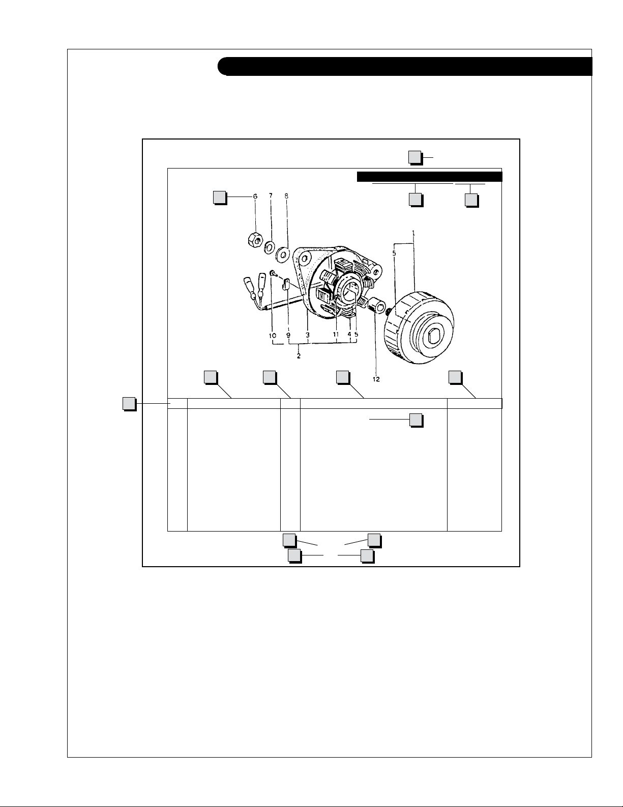
Reading a Parts Page
IMPORTANT:
Before selecting parts, be sure that you are choosing parts from the correct page.
Check the model designation at the page top.
Do not use this illustration for parts purchasing.
1
ELECTRICAL SYSTEM
ALTERNATOR ASSEMBLY: M - NL844
4
6
5
KEY PART NUMBER QTY. DESCRIPTION SERIALNUMBER
0 185046210 1 Alternator Assembly 1 185446219 1 Flywheel, complete 2 185446217 1 Plate, complete 3 185716200 1 Plate 4 185446218 1 Stator, complete 5 040126210 2 Bearing 6 020210010 1 Nut 7 027100010 1 Spring washer 8 026100010 1 Washer 9 185446220 1 Clamp 10 015140408 1 Screw 11 015140425 2 Screw 12 199236510 1 Collar -
7
8
10
3
2
9
13
11
P844 06/96
5 - 2
14
12
REFERENCES:
1. Grouping section title. 7. Quantity of parts used.
2. Model designation of equipment that uses parts 8. Description of each component part.
listedonthispage. 9. Serialnumberofunitthepartts.
3. Title and description of assembly. 10. Assembly or kit designated by Key 0 or ••/•.
4. Drawing numbers that correspond to key 11. Grouping index number.
columnnumbersforpartsidentication. 12. Pagenumberwithinthegroupingindex.
5. Key column for locating parts shown on drawing. 13. Manual title.
6. Part number. 14. Page publication date.
NOTE: a Arrows always point toward the front of the engine.
P6108 06/02
III
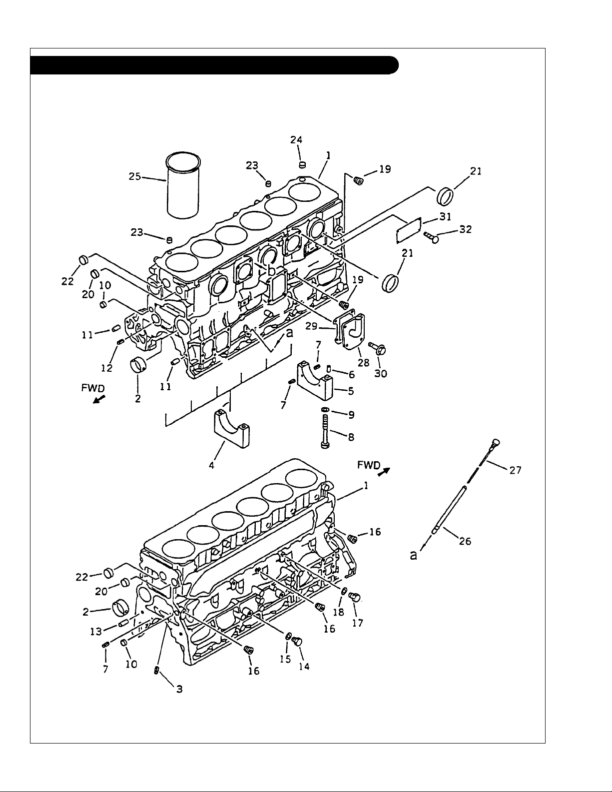
GROUP 1 - ENGINE
Cylinder Block L-M6108T-A-AQ
P6108 06/02
1 - 0
Figure 0201
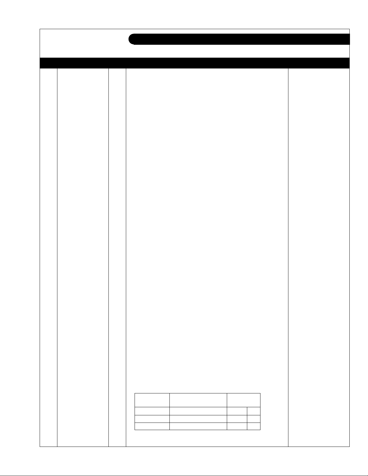
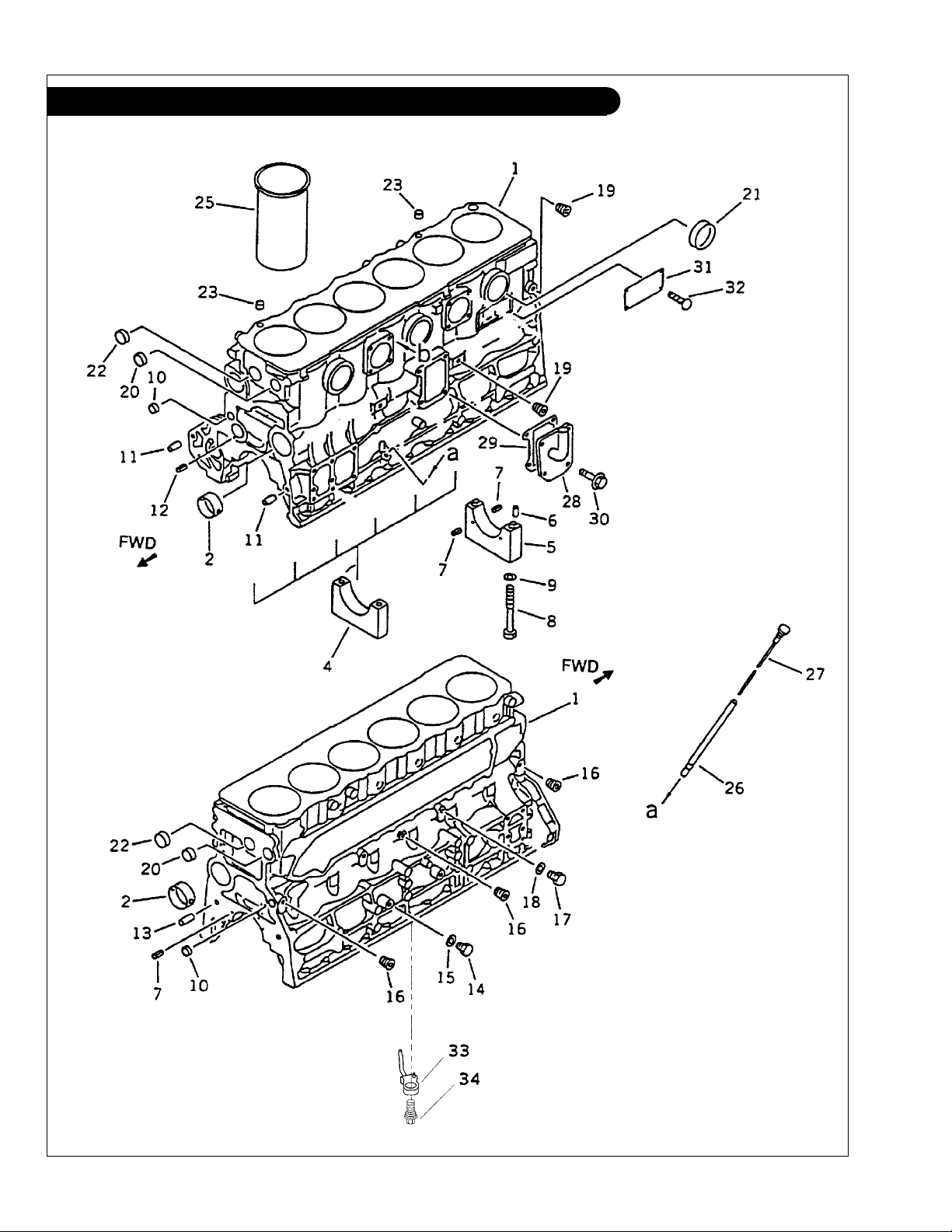
GROUP 1 - ENGINE
Cylinder Block L-M6108T-A-QA
KEY PART NUMBER QTY DESCRIPTION SERIAL NUMBER
1 6222-21-1101 1 Cylinder Block Assembly (includes keys #2 - #24) 2 6221-21-1410 4 Camshaft Bushing 3 04025-00408 ** Spring Pin 4 6222-29-1210 6 Main Bearing Cap 5 6222-29-1250 1 Main Bearing Cap 6 04020-00514 2 Dowel Pin 7 04025-00408 6 Spring Pin 8 6221-21-1710 14 Bolt 9 6130-32-1361 14 Washer 10 07046-42216 2 Expansion Plug 11 6136-21-1911 2 Dowel Ring 12 04025-00512 1 Spring Pin 13 04020-01228 2 Dowel Pin 14 07040-11209 2 Plug 15 07005-01212 2 Gasket 16 07043-70108 3 Plug -
17 07040-11007 1 Plug 18 07005-01012 1 Gasket 19 07043-70211 2 Plug 20 07046-43016 2 Expansion Plug (064200030) 21 07046-46520 5 Expansion Plug 22 07046-43516 2 Expansion Plug 23 6221-21-1790 2 Bushing 24 07046-42010 1 Expansion Plug -
25 6222-23-2211 ** Cylinder Liner
6222-23-2221 ** Cylinder Liner
6222-23-2231 ** Cylinder Liner
26 6221-21-5410 1 Dipstick Tube
27 6206-21-5310 1 Dipstick
28 28-05701 1 Cover
6221-21-7210 1 Cover
(L-M) -
(NL) -
29 6136-21-7830 1 Gasket 30 01435-01025 4 Bolt 31 09605-01425 1 Name Plate
32 04418-02550 4 Screw -
***
See Dipstick & Tube for Heat Exchanged Units
(S) *
(M) *
(L) *
(Keel cooled Propulsion Units) *** -
(Keel cooled Propulsion Units) *** -
(limited supply) -
**As required
* *NOTE: For each cylinder, check that the mark on the
cylinder liner and the stamped mark (S, M or L)
on the top face of right side of the cylinder
block correctly coincide.
LINER MARK
BLOCK MARK LINER PART NO. Bottom Top
S 6222-23-2211 S I
M 6222-23-2221 M II
L 6222-23-2231 L III
P6108 06/02
1 - 1
GROUP 1 - ENGINE
Cylinder Block L-M6108T2-A2
P6108 06/02
1 - 2
Figure 0201a

GROUP 1 - ENGINE
Cylinder Block L-M6108T2-A2
KEY PART NUMBER QTY DESCRIPTION SERIAL NUMBER
1 6221-23-1120 1 Cylinder Block Assembly (includes keys #2 - #24) 2 6221-21-1410 4 Camshaft Bushing 4 6222-29-1210 6 Main Bearing Cap 5 6222-29-1250 1 Main Bearing Cap 6 04020-00514 2 Dowel Pin 7 04025-00408 6 Spring Pin 8 6221-21-1710 14 Bolt 9 6130-32-1361 14 Washer 10 07046-42216 2 Expansion Plug 11 6136-21-1911 2 Dowel Ring 12 04025-00512 1 Spring Pin 13 04020-01228 2 Dowel Pin 14 07040-11209 2 Plug 15 07005-01212 2 Gasket 16 07043-70108 3 Plug 17 07040-11007 1 Plug -
18 07005-01012 1 Gasket -
19 07043-70211 2 Plug -
20 07046-43016 2 Expansion Plug (064200030) -
21 07046-45016 3 Expansion Plug -
22 07046-43516 2 Expansion Plug -
23 6221-21-1790 2 Bushing -
25 6222-23-2211 ** Cylinder Liner
6222-23-2221 ** Cylinder Liner
6222-23-2231 ** Cylinder Liner
26 6221-21-5410 1 Dipstick Tube
27 6206-21-5310 1 Dipstick 28 28-05701 1 Cover
6221-21-7210 1 Cover
(L-M) -
(NL) -
29 6136-21-7830 1 Gasket 30 01435-01025 4 Bolt 31 09605-01425 1 Name Plate
32 04418-02550 1 Screw 33 6222-23-1810 6 Piston Cooling Nozzle 34 6222-23-1820 6 Check Valve -
(S) * -
(M) * -
(L) * -
(Keel Cooled) -
(limited supply) -
**As required
**NOTE: For each cylinder, check that the mark on the
cylinder liner and the stamped mark (S, M or L)
on the top face of right side of the cylinder
block correctly coincide.
LINER MARK
BLOCK MARK LINER PART NO. Bottom Top
S 6222-23-2211 S I
M 6222-23-2221 M II
L 6222-23-2231 L III
P6108 06/02
1 - 3
GROUP 1 - ENGINE
Crankshaft Assembly
P6108 06/02
1 - 4
Figure 0231a

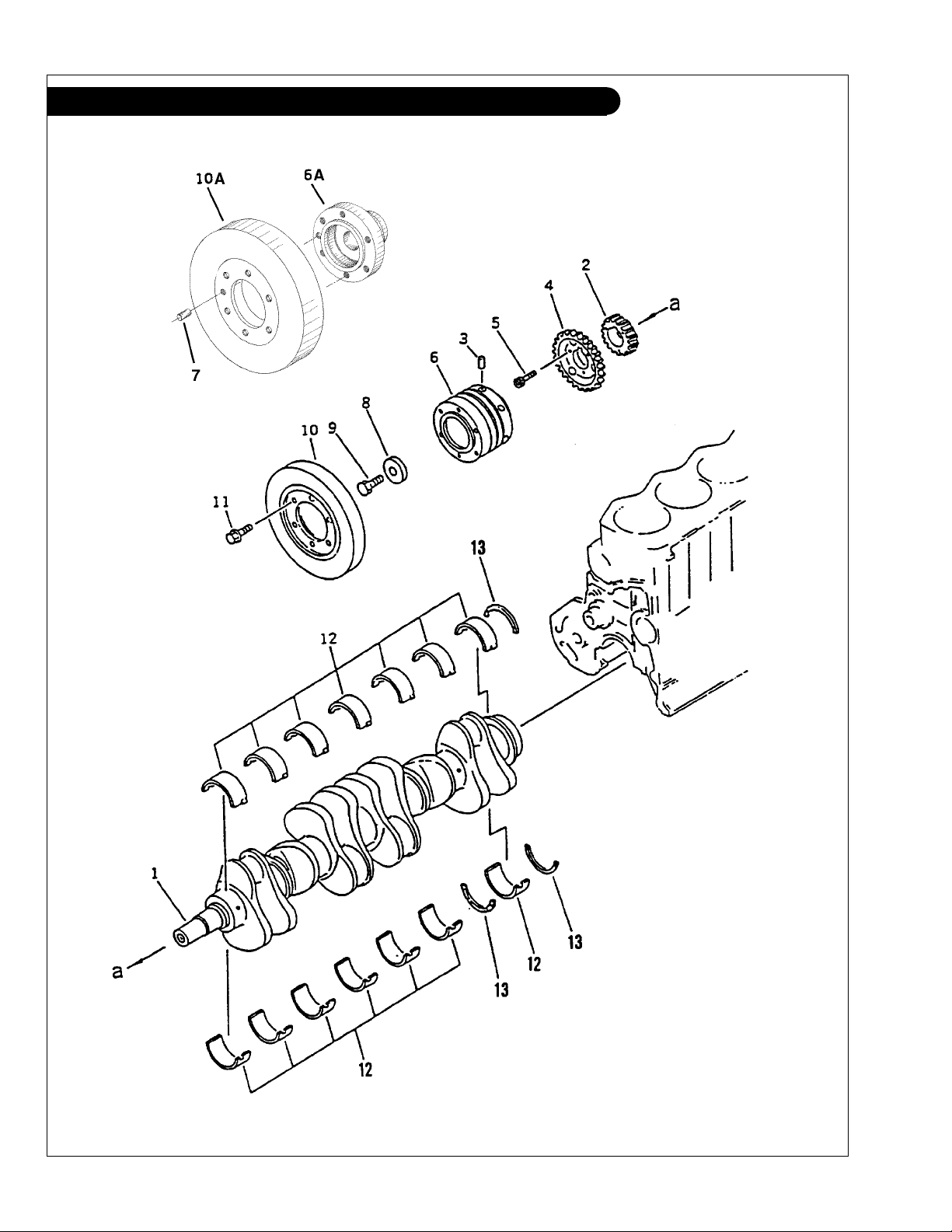
GROUP 1 - ENGINE
Crankshaft Assembly
KEY PART NUMBER QTY DESCRIPTION KOMATSU S/N
1 6222-35-1900 1 Crankshaft Assembly (includes key #2) Up to - 17508
6222-35-1901 1 Crankshaft Assembly
2 6222-35-1920 1 Gear Up to - 17508
6222-35-1921 1 Gear From 17509 3 6138-31-1460 1 Pin From 12825 4 6222-35-1930 1 Gear, Oil Pump Drive 5 01252-30825 3 Bolt Up to - 17508
6136-31-1240 3 Bolt Up to - 22179
01437-00830 3 Bolt From 22180 6 6138-31-1452 1 Pulley (Early Production) Up to - 12824
6A 6222-35-1940 1 Adapter (Late Production) Up to - 17508
6222-35-1941 1 Adapter (Late Production) Up to - 22179
6222-35-1942 1 Adapter (Late Production) From 22180 7 04020-01228 1 Pin (used with #6A & #10A) From 12825 8 6136-31-1431 1 Plate 9 01050-31845 1 Bolt 10 6138-31-8100 1 Damper (Early Production) Up to - 12824
10A 6151-31-8300 1 Damper (Late Production) From 12825 11 01435-01220 6 Capscrew, Hex Head Flanged, M12 x 1.75 x 20 mm 12 6221-21-8010 7 Main Bearing Assembly, Std. 6221-29-8010 7 Main Bearing Assembly, undersize 0.25 mm 6221-28-8010 7 Main Bearing Assembly, undersize 0.50 mm 6221-27-8010 7 Main Bearing Assembly, undersize 0.75 mm 6221-26-8010 7 Main Bearing Assembly, undersize 1.00 mm 13 6221-21-8050 1 Thrust Bearing Assembly, Std. -
6221-29-8050 1 Thrust Bearing Assembly, oversize 0.25 mm -
6221-28-8050 1 Thrust Bearing Assembly, oversize 0.50 mm -
6221-27-8050 1 Thrust Bearing Assembly, oversize 0.75 mm -
6221-26-8050 1 Thrust Bearing Assembly, oversize 1.00 mm -
(includes key #2) From 17509 -
P6108 06/02
1 - 5
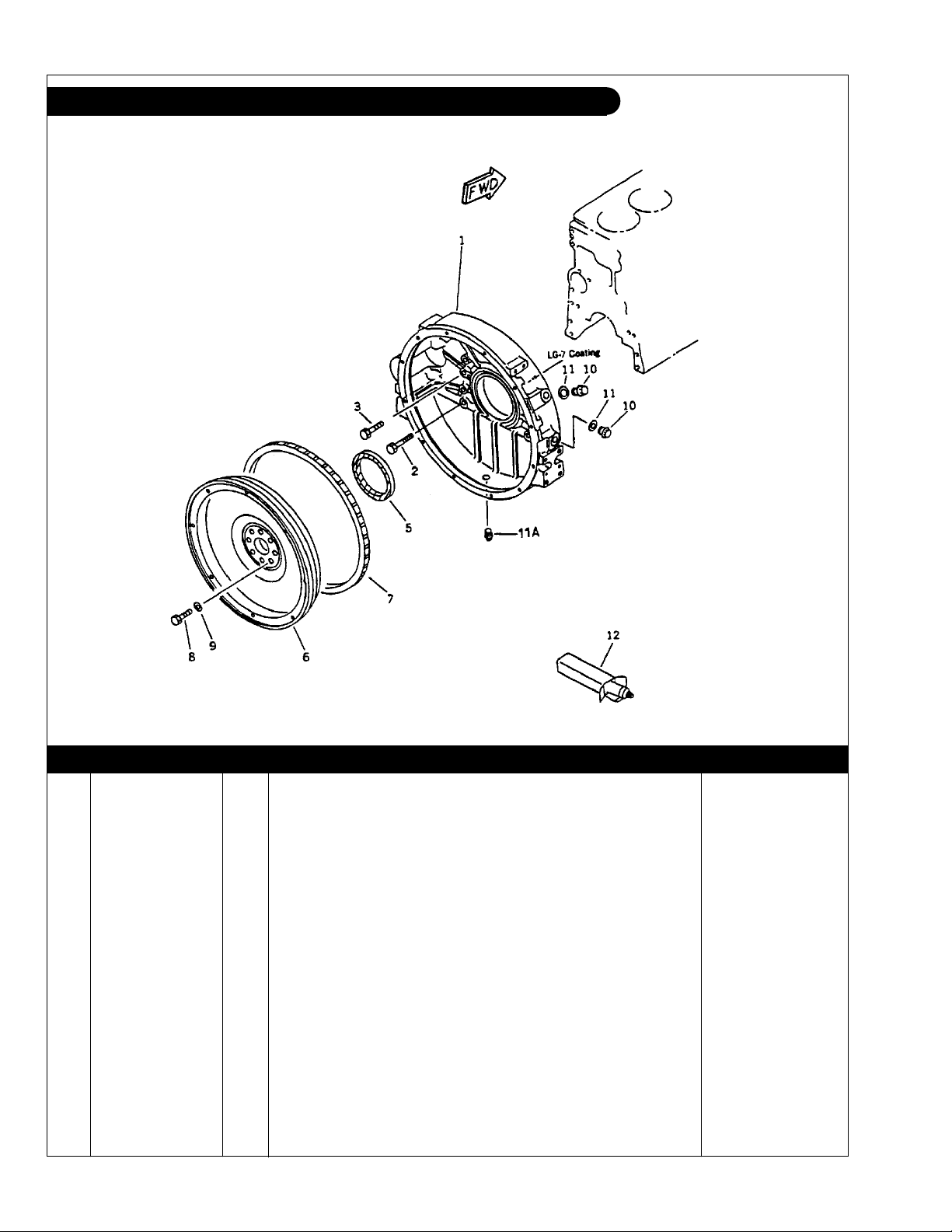
GROUP 1 - ENGINE
Flywheel & Housing SAE #3/ #11-1/2 L6108
Figure 0221
KEY PART NUMBER QTY DESCRIPTION SERIAL NUMBER
1 6221-21-4110 1 Flywheel Housing SAE#3 2 01435-01255 2 Capscrew, Hex Head Flanged, M12 x 1.75 x 55 mm,
3 01435-01245 9 Capscrew, Hex Head Flanged, M12 x 1.75 x 45 mm,
Grade 10.9 -
Grade 10.9 -
5 6221-21-4510 1 Rear Seal 6221-21-4520 1 Rear Main Seal (Repair Type) 6 31-65702 1 Flywheel Assembly SAE #11-1/2
7 6221-31-4190 1 Ring Gear
(122 Teeth) -
(includes key #7) -
8 01050-31435 8 Capscrew, Hex Head M14 x 1.5 x 35 mm 9 6130-32-1361 8 Flat Washer M14 Special 10 6114-11-8910 2 Plug 11 07005-02216 2 Gasket 11A 07042-00415 1 Plug 12 09920-00150 ** Liquid Gasket LG-7 -
**As required
P6108 06/02
1 - 6
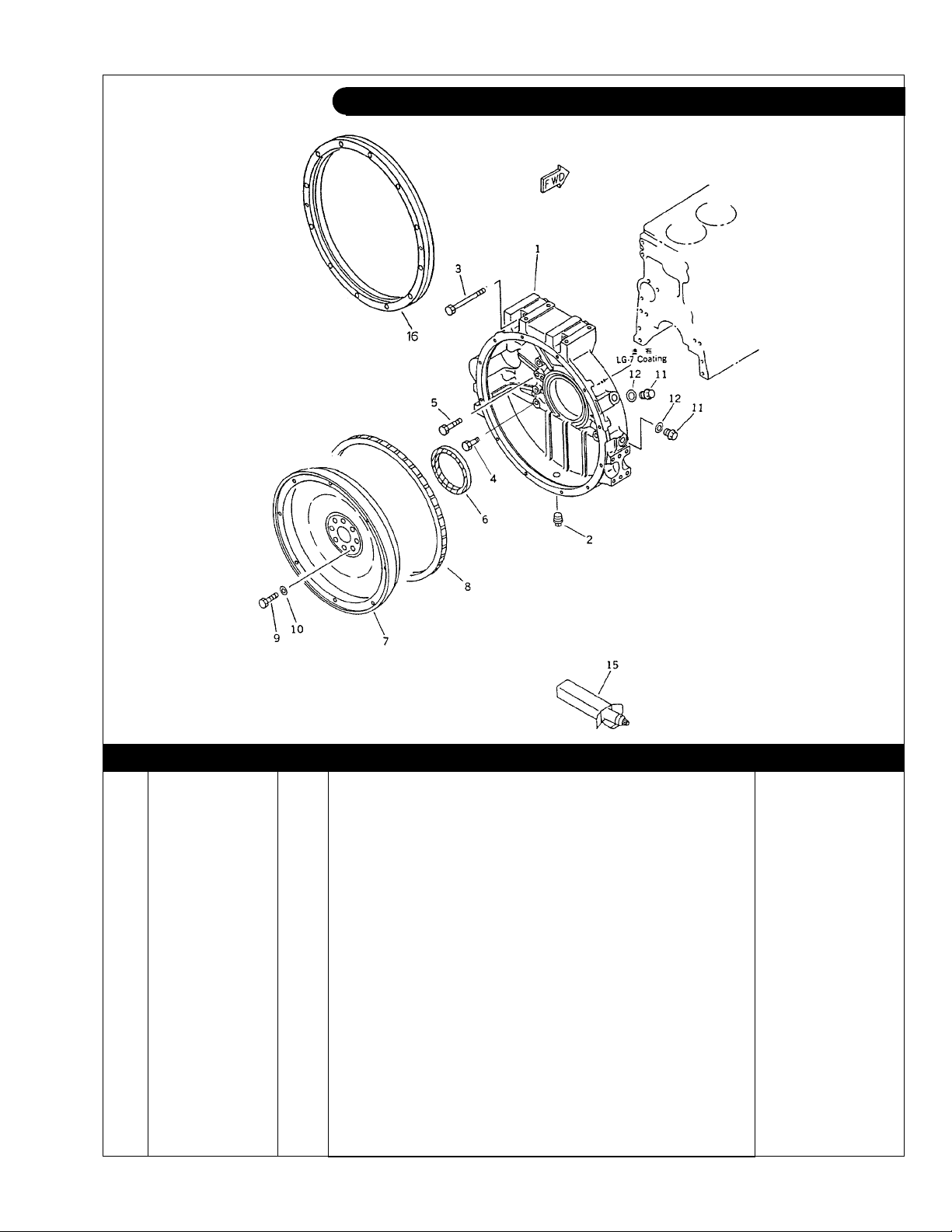
GROUP 1 - ENGINE
Flywheel & Housing SAE #1/ #14 L-M6108
Figure 0221 (ywheel6108)
KEY PART NUMBER QTY DESCRIPTION SERIAL NUMBER
1 6222-21-4111 1 Flywheel Housing SAE#1 2 07042-00415 1 Plug 3 01436-01205 2 Capscrew, Hex Head Flanged M12 x 1.75 x 105 mm,
4 01435-01255 2 Capscrew, Hex Head Flanged M12 x 1.75 x 55 mm,
5 01435-01245 9 Capscrew, Hex Head Flanged M12 x 1.75 x 45 mm,
Grade 10.9 -
Grade 10.9 -
Grade 10.9 -
6 6221-21-4510 1 Rear Main Seal 6221-21-4520 1 Rear Main Seal
7 6221-31-4170 1 Flywheel Assembly SAE #14
8 6150-31-1351 1 Ring Gear
(Repair Type) -
(includes key #8) -
(148 Teeth) -
9 01050-31465 8 Capscrew, Hex Head M14 x 1.5 x 65 mm 10 6130-32-1361 8 Flat Washer M14 Special 11 6114-11-8910 2 Plug 12 07005-02216 2 Gasket 15 09920-00150 ** Liquid Gasket, LG-7 16 6221-21-4940 1 Adapter -
**As required
P6108 06/02
1 - 7
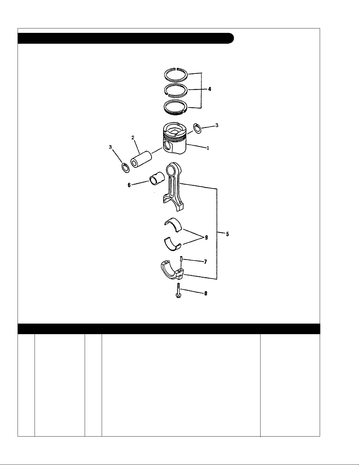
GROUP 1 - ENGINE
Piston & Connecting Rod L-M 6108T & A
Figure 0235
KEY PART NUMBER QTY DESCRIPTION SERIAL NUMBER
1 6222-31-2110 6 Piston 2 6221-31-2410 6 Piston Pin 3 04065-04518 12 Snap Ring 4 6221-31-2200 6 Piston Ring Set 5 6221-31-3100 6 Connecting Rod Assembly
6 6221-31-3130 1 Bushing 7 02400-10313 2 Dowel Pin 8 6221-31-3310 2 Bolt 9 6222-31-3040 6 Connecting Rod Bearing Assembly, Std. 6222-39-3040 6 Connecting Rod Bearing Assembly, undersize 0.25 mm 6222-38-3040 6 Connecting Rod Bearing Assembly, undersize 0.50 mm 6222-37-3040 6 Connecting Rod Bearing Assembly, undersize 0.75 mm 6222-36-3040 6 Connecting Rod Bearing Assembly, undersize 1.00 mm -
(includes keys #6 - #8) -
P6108 06/02
1 - 8

GROUP 1 - ENGINE
Piston & Connecting Rod L-M 6108T2 & A2
Figure 0235
KEY PART NUMBER QTY DESCRIPTION SERIAL NUMBER
1 6222-35-2150 6 Piston 2 6221-31-2410 6 Piston Pin 3 04065-04518 12 Snap Ring 4 6221-31-2200 6 Piston Ring Set 5 6222-31-3100 6 Connecting Rod Assembly
6 6222-31-3130 1 Bushing 7 02400-10313 2 Dowel Pin 8 6221-31-3310 2 Bolt 9 6222-31-3050 6 Connecting Rod Bearing Assembly, Std. 6222-39-3050 6 Connecting Rod Bearing Assembly, undersize 0.25 mm 6222-38-3050 6 Connecting Rod Bearing Assembly, undersize 0.50 mm 6222-37-3050 6 Connecting Rod Bearing Assembly, undersize 0.75 mm 6222-36-3050 6 Connecting Rod Bearing Assembly, undersize 1.00 mm -
(includes keys #6 - #8) -
P6108 06/02
1 - 9
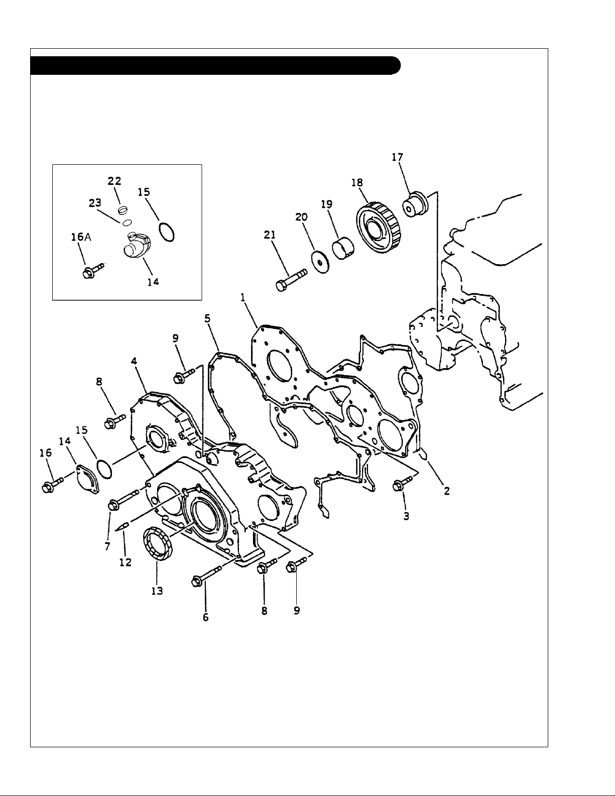
GROUP 1 - ENGINE
Timing Cover L-M 6108
Without Accessory Drive
P6108 06/02
1 - 10
Figure 0205A
GROUP 1 - ENGINE
Timing Cover L-M 6108
Without Accessory Drive
KEY PART NUMBER QTY DESCRIPTION KOMATSU S/N
1 6222-21-3221 1 Cover Backing Plate Up to - 12824
2 6221-21-3820 1 Gasket
3 01435-00820 4 Capscrew, Hex Head Flanged M8 x 1.25 x 20 mm,
4 6221-21-3120 1 Timing Cover Up to - 12824
5 6221-21-3811 1 Gasket
6 01435-00885 2 Capscrew, Hex Head Flanged M8 x 1.25 x 85 mm,
7 01435-00895 2 Capscrew, Hex Head Flanged M8 x 1.25 x 95 mm,
8 01435-00855 8 Capscrew, Hex Head Flanged M8 x 1.25 x 55 mm,
9 01435-00865 4 Capscrew, Hex Head Flanged M8 x 1.25 x 65 mm,
12 6221-21-3910 1 Pin Up to - 12824
13 6136-22-3510 1 Front Seal
14 6144-81-5151 1 Cover Up to - 12824
6142-82-5112 1 Tachometer Drive 15 07000-03050 1 O-Ring Up to - 12824
16 01435-00612 2 Capscrew, Hex Head Flanged M6 x 1.0 x 12 mm,
16A 01435-00616 2 Capscrew, Hex Head Flanged M6 x 1.0 x 16 mm,
17 6221-21-2410 1 Idler Shaft Up to - 12824
18 6221-31-6300 1 Idler Gear Assembly
19 6221-31-6340 1 Bushing Up to - 12824
20 6221-21-2420 1 Washer Up to - 12824
21 01010-61480 1 Capscrew, Hex Head M14 x 2.0 x 80 mm Up to - 12824
22 6130-82-5260 1 Cap 23 6130-82-5270 1 Gasket -
(Formerly #6221-21-3890) Up to - 12824
Grade 10.9 Up to - 12824
(Formerly #6221-21-3810) Up to - 12824
Grade 10.9 Up to - 12824
Grade 10.9 Up to - 12824
Grade 10.9 Up to - 12824
Grade 10.9 Up to - 12824
(Formerly #6136-21-3510) Up to - 12824
Grade 10.9 Up to - 12824
Grade 10.9
(includes keys #19) Up to - 12824
P6108 06/02
1 - 11
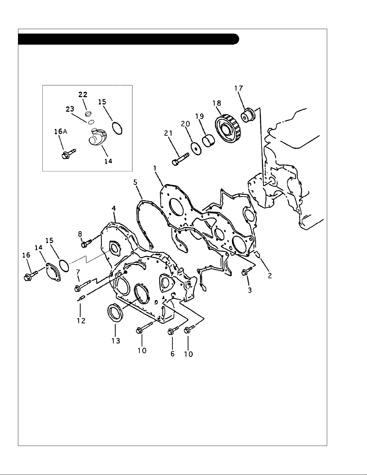
GROUP 1 - ENGINE
Timing Cover L-M 6108
With Accessory Drive
P6108 06/02
1 - 12
Figure 0205B
GROUP 1 - ENGINE
Timing Cover L-M 6108
With Accessory Drive
KEY PART NUMBER QTY DESCRIPTION KOMATSU S/N
1 6222-21-3221 1 Cover Backing Plate From 12825 2 6221-21-3820 1 Gasket
3 01435-00820 4 Capscrew, Hex Head Flanged M8 x 1.25 x 20 mm,
4 6222-25-3110 1 Timing Cover
5 6221-21-3811 1 Gasket
6 01435-00880 2 Capscrew, Hex Head Flanged M8 x 1.25 x 80 mm,
7 01436-00800 3 Capscrew, Hex Head Flanged M8 x 1.25 x 100 mm,
8 01435-00855 6 Capscrew, Hex Head Flanged M8 x 1.25 x 55 mm,
10 01435-00890 9 Capscrew, Hex Head Flanged M8 x 1.25 x 90 mm,
12 6221-21-3910 1 Pin
13 6136-22-3510 1 Front Seal
14 6144-81-5151 1 Cover
6142-82-5112 1 Tachometer Drive
15 07000-03050 1 O-Ring
16 01435-00612 2 Capscrew, Hex Head Flanged M6 x 1.0 x 12 mm,
16A 01435-00616 2 Capscrew, Hex Head Flanged M6 x 1.0 x 16 mm,
17 6221-21-2410 1 Idler Shaft
18 6221-31-6300 1 Idler Gear Assembly
19 6221-31-6340 1 Bushing
20 6221-21-2420 1 Washer
21 01010-61480 1 Capscrew, Hex Head M14 x 2.0 x 80 mm
22 6130-82-5260 1 Cap
23 6130-82-5270 1 Gasket
(Formerly #6221-21-3890)
Grade 10.9
(Formerly #6221-21-3810)
Grade 10.9
Grade 10.9
Grade 10.9
Grade 10.9
(Formerly #6136-21-3510)
Grade 10.9
Grade 10.9
(includes keys #19)
P6108 06/02
1 - 13

GROUP 1 - ENGINE
Accessory Drive Assembly L-M6108
Figure 0208A
KEY PART NUMBER QTY DESCRIPTION SERIAL NUMBER
•• 6222-25-3401 1 Accessory Drive Assembly (includes keys 1 - 9) 1 6222-25-3411 1 Housing 2 6150-25-3422 1 Shaft 3 06030-05204 1 Bearing 4 04065-04718 1 Snap Ring 5 6222-25-3450 1 Gear
(23 Teeth) -
6 06030-06304 1 Bearing 7 07012-00035 1 Oil Seal 8 6222-25-3441 1 Hub -
9 07000-72060 1 O-Ring 10 01435-01035 3 Capscrew Hex Head Flanged M10 x 1.5 x 35 mm,
Grade 10.9 -
11 6222-25-3430 1 Pully 12 01435-00816 4 Capscrew Hex Head Flanged M8 x 1.25 x 16 mm,
Grade 10.9 -
13 6222-25-9330 1 Tube, Oil Supply 14 04434-50608 1 Clamp 15 01435-00816 1 Capscrew Hex Head Flanged M8 x 1.25 x 16 mm,
Grade 10.9 -
16 07206-30710 1 Banjo Bolt 17 07005-01012 2 Sealing Washer -
P6108 06/02
1 - 14
GROUP 1 - ENGINE
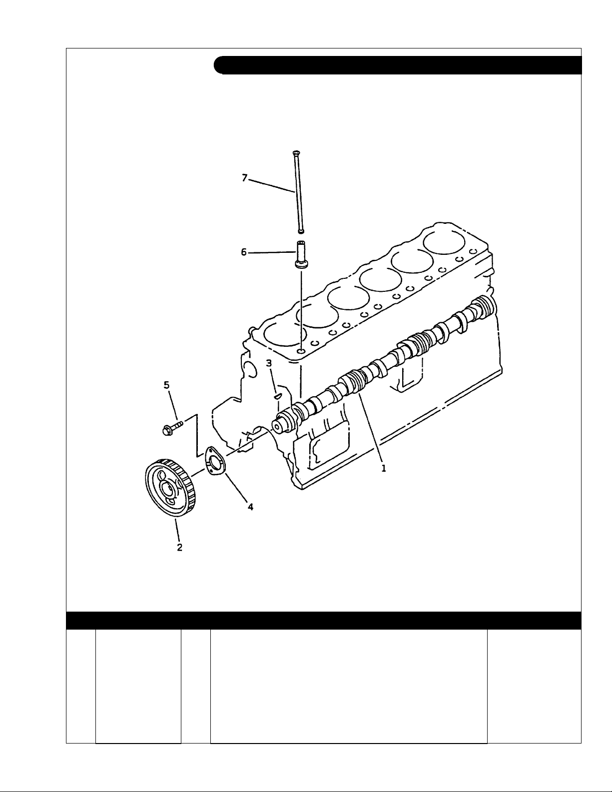
Camshaft L-M 6108
Figure 0241
KEY PART NUMBER QTY DESCRIPTION SERIAL NUMBER
•• 6221-41-1100 1 Camshaft Assembly (includes keys #1 - #4) 1 6221-41-1110 1 Camshaft 2 6221-41-1120 1 Gear 3 04010-00516 1 Key 4 6204-41-1131 1 Thrust Plate 5 01435-00820 2 Bolt 6 6221-41-2110 12 Tappet 7 6221-41-3110 12 Push Rod -
P6108 06/02
1 - 15
GROUP 1 - ENGINE
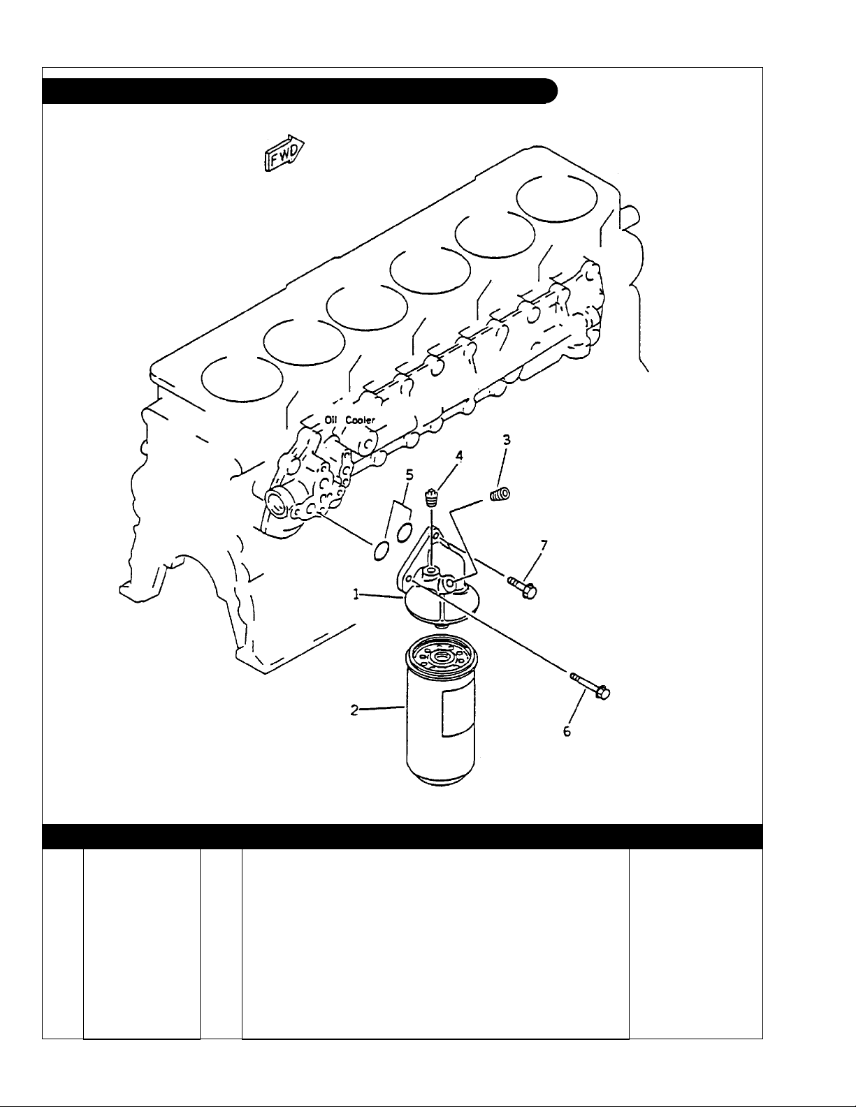
Oil Filter & Mounting L-M6108
Figure 0311
KEY PART NUMBER QTY DESCRIPTION SERIAL NUMBER
•• 6136-51-5102 1 Oil Filter Assembly (includes keys 1 - 3) 1 6136-51-5111 1 Bracket 2 24-05701 1 Oil Filter 3 07043-00108 ** Plug 4 07042-70108 ** Plug 5 07000-73028 2 O-Ring 6 01435-00885 1 Capscrew, Hex Head Flanged M8 x 1.25 x 85 mm,
7 01435-01030 2 Capscrew, Hex Head Flanged M10 x 1.5 x 30 mm,
**
As required
P6108 06/02
Grade 10.9 -
Grade 10.9 -
1 - 16

GROUP 1 - ENGINE
Oil Pan L-M 6108
Figure 0211
KEY PART NUMBER QTY DESCRIPTION SERIAL NUMBER
1 36-75703 1 Oil Pan with Right Side Dipstick Tube 1 6136-21-5230 1 Oil Pan 2 36-75702 1 Bushing, M24 x 1.5 x 3/8 O-Ring Port 3 07000-13022 1 O-Ring
4 6136-21-5821 1 Gasket 5 01435-00816 38 Capscrew, Hex Head Flanged M8 x 1.25 x 16 mm,
6 36-75716 1 Dipstick, 0 Degree Down Angle 36-75723 1 Dipstick, 3 Degree Down Angle 36-75722 1 Dipstick, 5 Degree Down Angle 36-75726 1 Dipstick, 7 Degree Down Angle 36-75724 1 Dipstick, 10 Degree Down Angle -
(Can use 16-15004, formerly #07000-03022) -
Grade 10.9 -
P6108 06/02
1 - 17
GROUP 1 - ENGINE
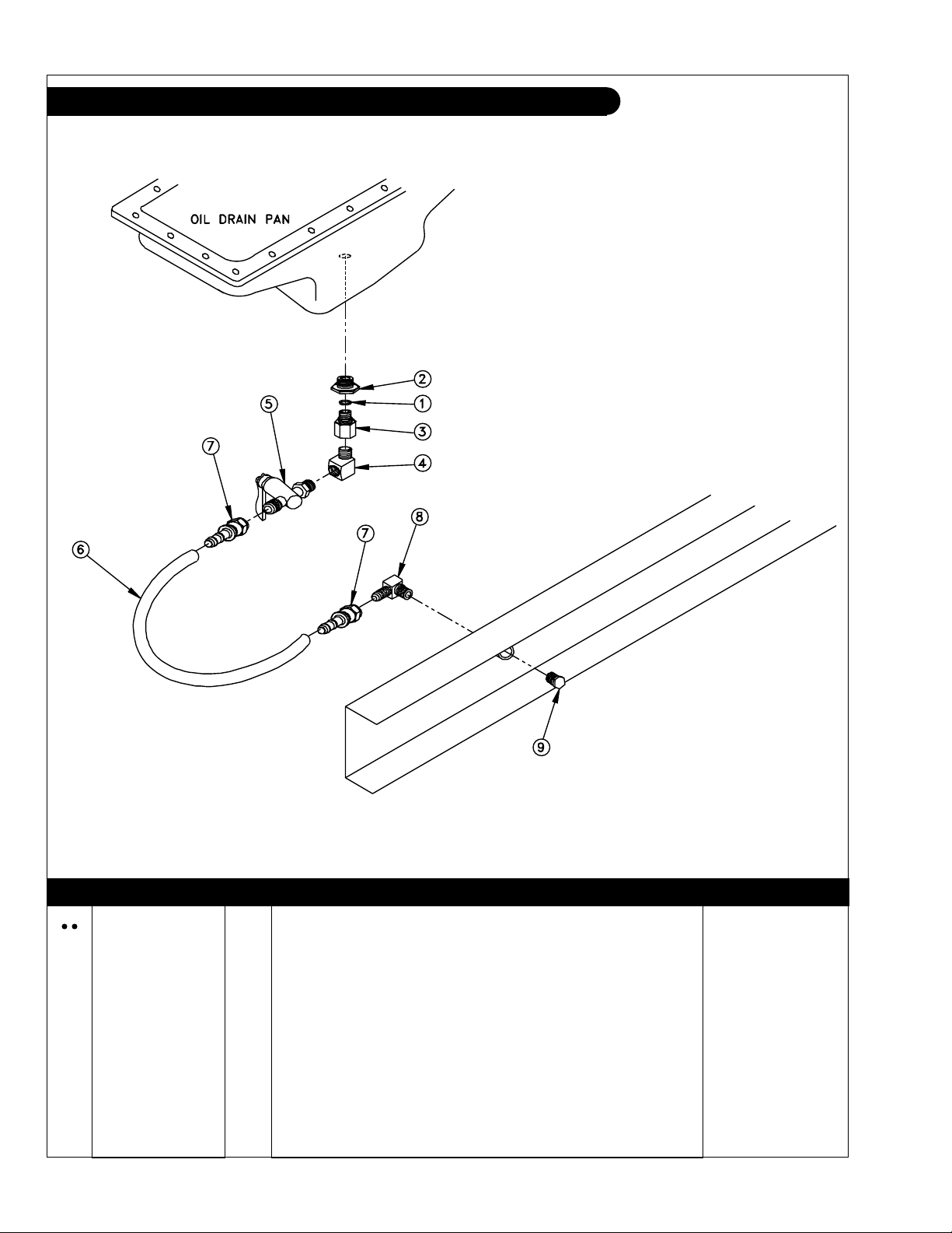
Oil Drain M-NL 6108
A-5870/ B-6498
KEY PART NUMBER QTY DESCRIPTION SERIAL NUMBER
36-75710 1 Oil Drain (includes all keys) 1 07000-03022 1 O-Ring 2 36-75702 1 Bushing, Stl. M24 x 1.5 x 3/8 OR Port 3 21-50001 1 Adapter, Stl. 3/8 NPT x 3/8 OR Port 4 21-51097 1 Elbow, 90 Degrees 3/8 NPT x 3/8 NPT 5 36-71002 1 Valve, Shut-Off, 3/8 NPT x 1/2-45T 6 18-71035 1 Hose, 1/2"ID x 18" 7 21-71042 1 Female Swivel Brass, 1/2 HB x 1/2-45T 8 21-01016 1 Male Elbow, 90 Degrees Brass, 1/2 NPT x 1/2-45T 9 21-10005 1 Plug, Hex Head, Stl. 1/2 NPT -
P6108 06/02
1 - 18
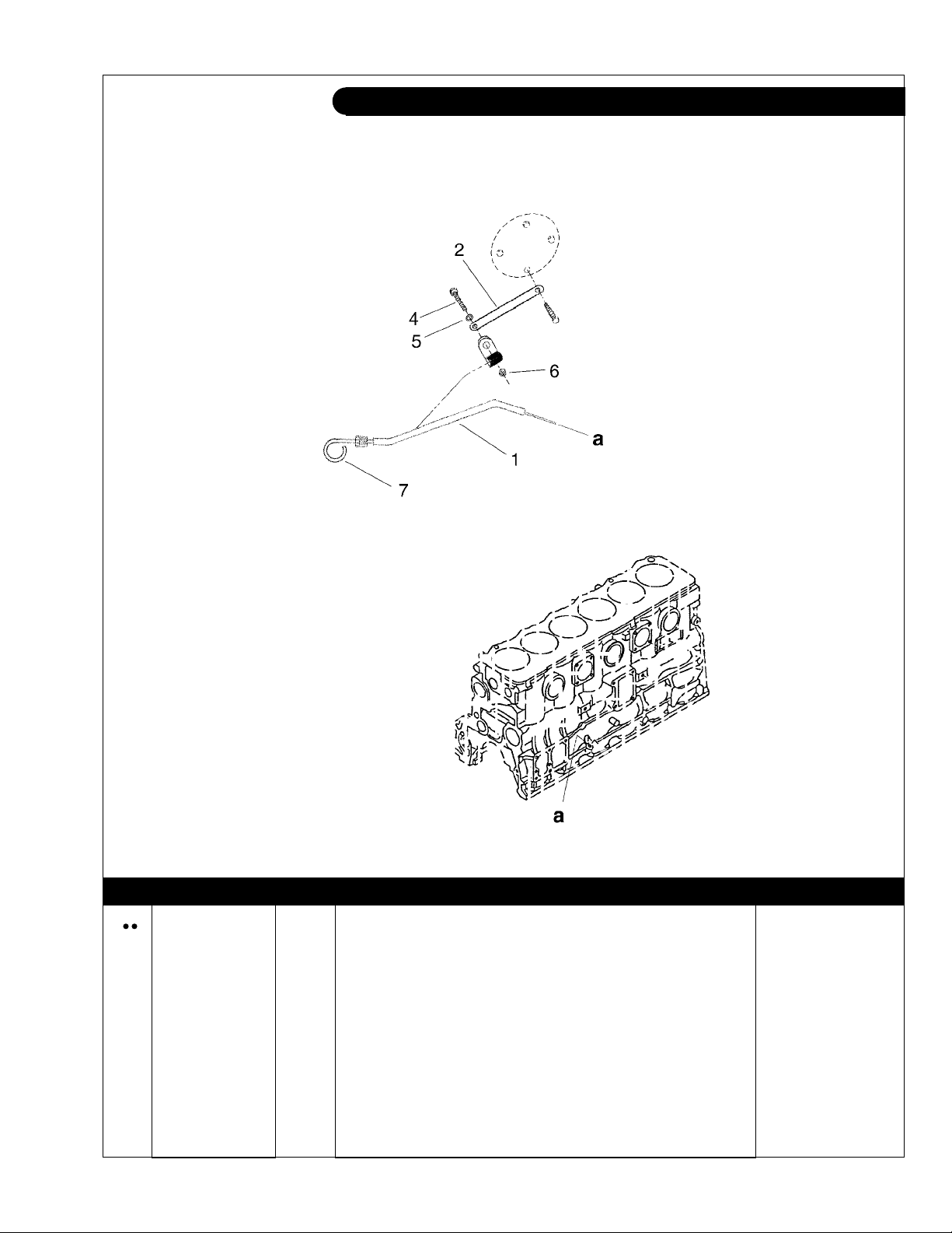
GROUP 1 - ENGINE
Dipstick L/M 6108
Heat Exchanged Units
6108dipstick
KEY PART NUMBER QTY DESCRIPTION SERIAL NUMBER
36-75706 1 Dipstick/ Tube Assembly 1 27-75703 1 Tube 2 23-75703 1 Bracket, Tube Support 3 19-53200 1 Adelle Clamp .50" I.D. 4 12-01131 1 Cap Screw, Hex Head M6 x 1.0 x 20 mm 5 15-00008 2 Flat Washer, M6 6 14-04803 1 Hex Nut, Nylock M6 x 1.0 7 36-75717 1 Dipstick Only -
P6108 06/02
1 - 19
GROUP 1 - ENGINE
Oil Pump & Suction Pick-up L-M6108T-A-AQ
P6108 06/02
1 - 20
Figure 0301

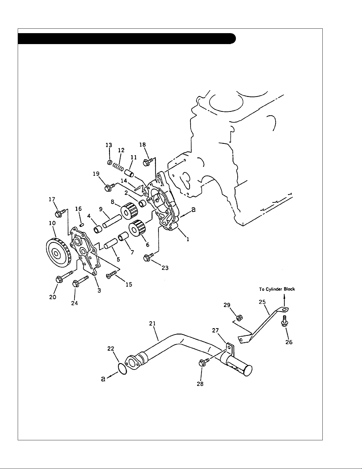
GROUP 1 - ENGINE
Oil Pump & Suction Pick-up L-M6108T-A-AQ
KEY PART NUMBER QTY DESCRIPTION SERIAL NUMBER
•• 6221-51-1100 1 Oil Pump Assembly (includes keys #1 - #17) 1 6222-55-1200 1 Body Assembly
2 6136-52-1220 1 Bushing 3 6221-51-1300 1 Cover Assembly
4 6136-52-1330 1 Bushing 5 6136-52-1320 1 Shaft -
•• 6136-52-1400 1 Gear Assembly
6 6136-52-1410 1 Gear 7 6136-52-1420 1 Bushing -
•• 6221-51-1500 1 Shaft Sub-Assembly
8 6136-52-1510 1 Gear 9 6221-51-1520 1 Shaft 10 6221-51-1610 1 Gear 11 6222-55-1640 1 Valve 12 6222-55-1650 1 Spring 13 6222-55-1660 1 Retainer 14 04050-14035 1 Cotter Pin 15 01236-40820 1 Screw 16 6136-52-1620 1 Pin 17 01435-00820 6 Capscrew, Hex Head, Flanged M8 x 1.25 x 20 mm
18 01435-00825 1 Capscrew, Hex Head, Flanged M8 x 1.25 x 25 mm
19 01435-00840 1 Capscrew, Hex Head, Flanged M8 x 1.25 x 40 mm
20 01435-00855 1 Capscrew, Hex Head, Flanged M8 x 1.25 x 55 mm
21 6221-51-6210 1 Oil Suction Pick-up 22 07000-73035 1 O-Ring 23 01435-00820 1 Capscrew, Hex Head, Flanged M8 x 1.25 x 20 mm
24 01435-00850 1 Capscrew, Hex Head, Flanged M8 x 1.25 x 50 mm
25 6221-51-6110 1 Bracket 26 01435-01020 1 Capscrew, Hex Head, Flanged M10 x 1.5 x 20 mm
27 6136-51-6230 1 Clamp 28 01435-00820 1 Capscrew, Hex Head, Flanged M8 x 1.25 x 20 mm
29 01584-00806 1 Nut -
(includes key #2) -
(includes keys #4 - #5) -
(includes keys #6 - #7) -
(includes keys #8 - #9) -
(Grade 10.9) -
(Grade 10.9) -
(Grade 10.9) -
(Grade 10.9) -
(Grade 10.9) -
(Grade 10.9) -
(Grade 10.9) -
(Grade 10.9) -
P6108 06/02
1 - 21

GROUP 1 - ENGINE
Oil Pump & Suction Pick-up L-M6108T2-A2
P6108 06/02
1 - 22
Figure 0301

GROUP 1 - ENGINE
Oil Pump & Suction Pick-up L-M6108T2-A2
KEY PART NUMBER QTY DESCRIPTION SERIAL NUMBER
•• 6222-55-1100 1 Oil Pump Assembly (includes keys #1 - #17) 1 6221-55-1200 1 Body Assembly
2 6136-52-1220 1 Bushing 3 6221-51-1300 1 Cover Assembly
4 6136-52-1330 1 Bushing 5 6136-52-1320 1 Shaft -
•• 6136-52-1400 1 Gear Assembly
6 6136-52-1410 1 Gear 7 6136-52-1420 1 Bushing -
•• 6221-51-1500 1 Shaft Sub-Assembly
8 6136-52-1510 1 Gear 9 6221-51-1520 1 Shaft 10 6221-51-1610 1 Gear 11 6222-55-1640 1 Valve 12 6222-55-1650 1 Spring 13 6222-55-1660 1 Retainer 14 04050-14035 1 Cotter Pin 15 01236-40820 1 Screw 16 6136-52-1620 1 Pin 17 01435-00820 6 Capscrew, Hex Head, Flanged M8 x 1.25 x 20 mm
18 01435-00825 1 Capscrew, Hex Head, Flanged M8 x 1.25 x 25 mm
19 01435-00840 1 Capscrew, Hex Head, Flanged M8 x 1.25 x 40 mm
20 01435-00855 1 Capscrew, Hex Head, Flanged M8 x 1.25 x 55 mm
21 6221-51-6210 1 Oil Suction Pick-up 22 07000-73035 1 O-Ring 23 01435-00820 1 Capscrew, Hex Head, Flanged M8 x 1.25 x 20 mm
24 01435-00850 1 Capscrew, Hex Head, Flanged M8 x 1.25 x 50 mm
25 6221-51-6110 1 Bracket 26 01435-01020 1 Capscrew, Hex Head, Flanged M10 x 1.5 x 20 mm
27 6136-51-6230 1 Clamp 28 01435-00820 1 Capscrew, Hex Head, Flanged M8 x 1.25 x 20 mm
29 01584-00806 1 Nut -
(includes key #2) -
(includes keys #4 - #5) -
(includes keys #6 - #7) -
(includes keys #8 - #9) -
(Grade 10.9) -
(Grade 10.9) -
(Grade 10.9) -
(Grade 10.9) -
(Grade 10.9) -
(Grade 10.9) -
(Grade 10.9) -
(Grade 10.9) -
P6108 06/02
1 - 23
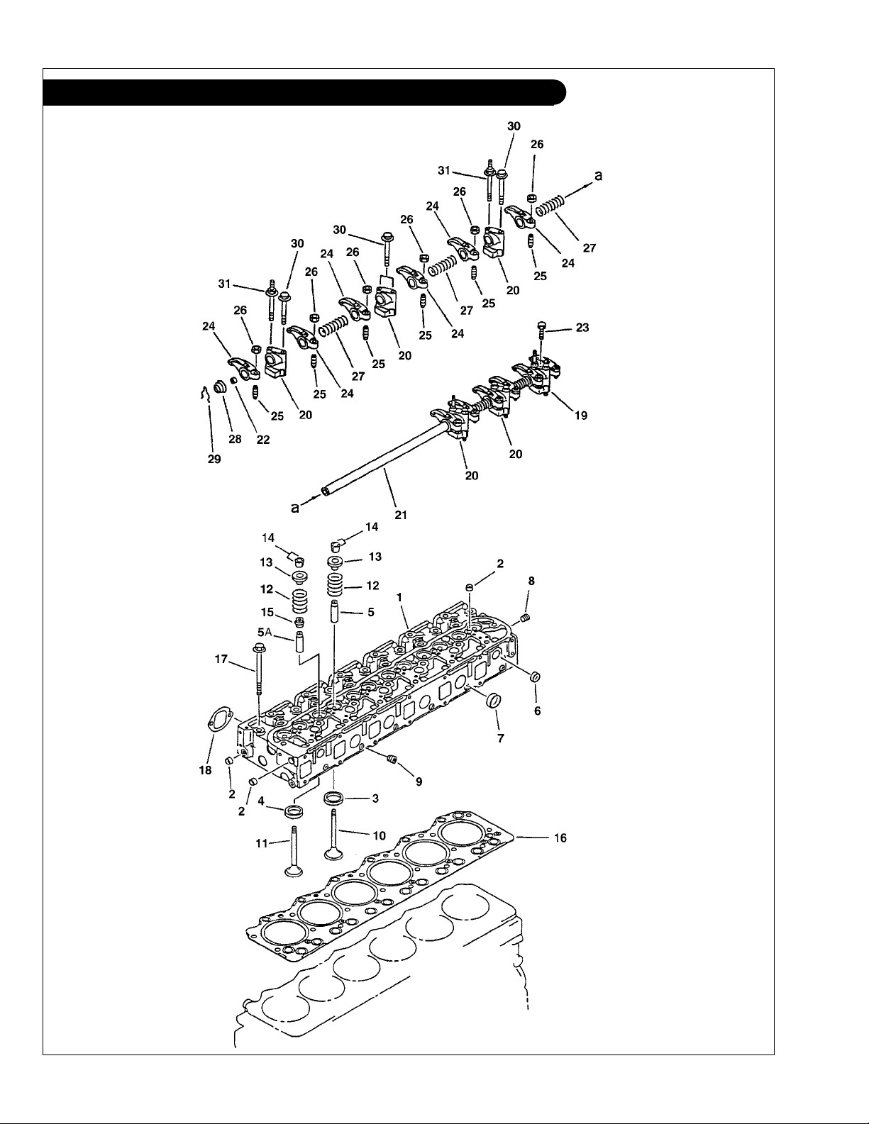
GROUP 1 - ENGINE
Cylinder Head & Valve Train L-M6108T-A-QA
P6108 06/02
1 - 24
Figure 0101& 0111
 Loading...