How it Works
Log In / Sign Up
Buy Points
How it Works
FAQ
Contact Us
Questions and Suggestions
Users
Northern Lights
Loading...
#
281PSL1500
281PSL1501
281PSL1502
282PSL1503
282PSL1504
282PSL1505
283PSL1506
283PSL1507
284PSL1508
361PSL1600
361PSL1601
361PSL1602
362PSL1604
362PSL1606
363PSL1607
431PSL6202
431PSL6204
431PSL6206
431PSL6208
432PSL6210
432PSL6212
433PSL6216
433PSL6220
A
and M20CR
and M38CR2
and NL1066H3
APM 2000
APR 63-5
ARC-102
AVALANCHE4 MULTI-GYM
E
Everbright BR31
Everbright Rear Drive SE01
G
GEM
GSC300
I
IM1000
2
L
L1064A
2
L1064D
2
L1066A
L1066H
L1066T
L1276A
L1276A2
L6108
L6125
L6140A
2
L6140AL
L6140AL2
2
L6170A
L844D
L944D
3
L984
LC6108
Lugger 0844K
Lugger L984
Lugger M20CL
Lugger M20CR
Lugger M30C
Lugger M30CW
Lugger M33CW
Lugger M673D
Lugger M673L
Lugger M673M
Lugger M773LW
Lugger M773LW2
Lugger M773LW3
Lugger M843NW2
Lugger M843NW3
Lugger M844K
Lugger M844LK
Lugger M944W
Lugger M984K
Lugger M984W
Lugger ML984
Lugger OM673
Lugger OM773LW2
Lugger OM843NW2
Lugger OM944W
Lugger ONL753W2
Lugger P984
LX-E
LX-E 34E
M
M1064A
3
M1064D
3
M1064H
2
M1064T1
3
M1064T2
3
M1066A1
2
M1066A2
2
M1066A3
2
M1066H
Loading...
Loading...
Nothing found
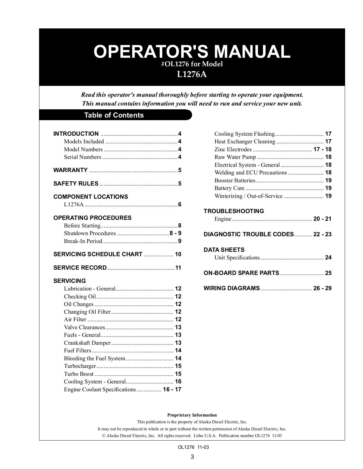
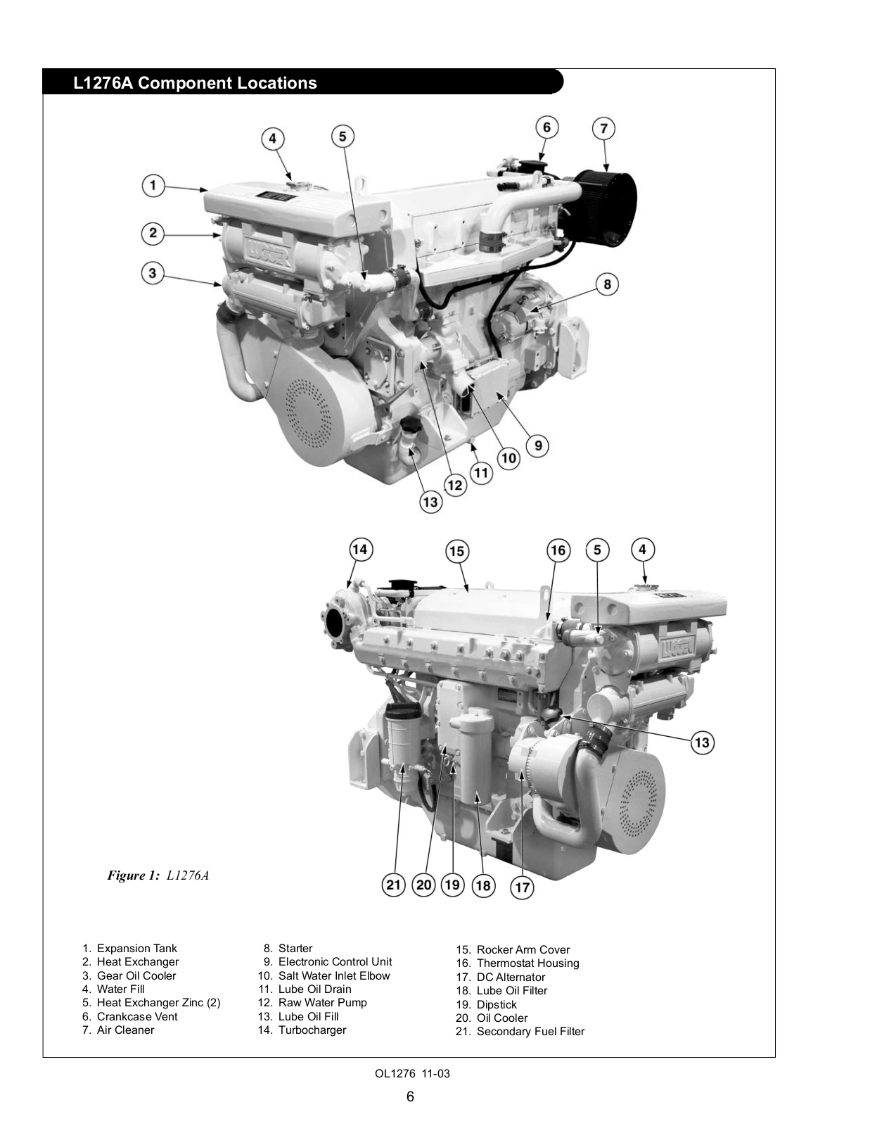
L1276A
Operator's Manual
25 pgs
1.14 Mb
0
Table of contents
Loading...
Northern Lights L1276A Operator's Manual
...
Northern Lights Operator's Manual
Download
Specifications and Main Features
Frequently Asked Questions
User Manual
Download
Page 1
Page 2
Page 3
Page 4
Page 5
Page 6
Page 7
Page 8
Page 9
Page 10
Page 11
Page 12
Page 13
Page 14
Page 15
Page 16
Page 17
Page 18
Page 19
Page 20
Page 21
Page 22
Page 23
Page 24
Page 25
Loading...
+
hidden pages
Unhide
You need points to download manuals.
1 point = 1 manual.
You can buy points or you can get point for every manual you upload.
Buy points
Upload your manuals