

Northern Lights OGSC300, GSC300 Owner's Manual
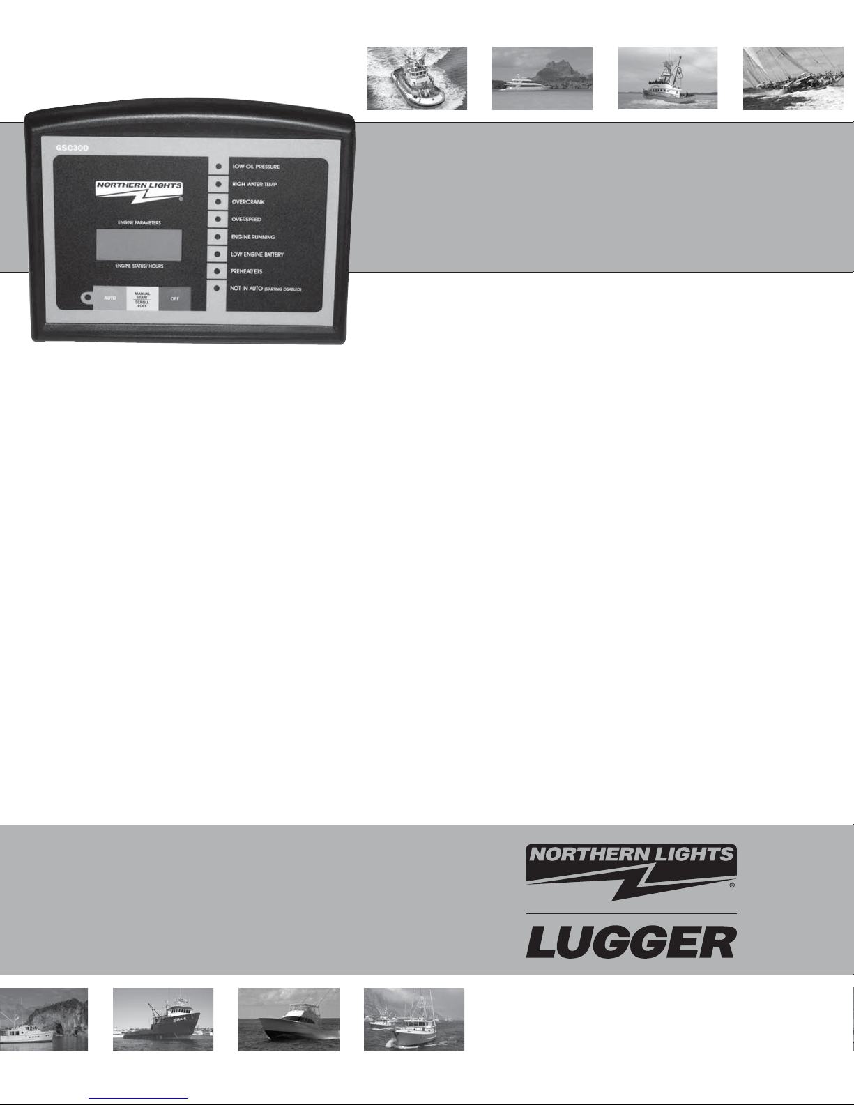
OGSC300
Auto Start Generator Set Controller
OPERATOR’S MANUAL
Marine Generators | Marine Diesel Engines | Land-Based Generators

Northern Lights
4420 14th Avenue N.W.
Seattle, WA 98107
Tel: (206) 789-3880
Fax: (206) 782-5455
Copyright ©2012 Northern Lights, Inc.
All rights reserved. Northern Lights™, and
the Northern Lights logo are trademarks of
Northern Lights, Inc.
Printed in U.S.A.
PART NO.: OGSC300 08/12

OPERATORS MANUAL
for GSC300
Auto Start Generator Set Controller
Please Read Manual Before Installing Unit
Table of Contents..........................................................................................................................................I
Warranty Policy ...........................................................................................................................................II
GSC300 Specifi cations..........................................................................................................................III- IV
Table of Contents
1 - GSC300 Product Number Itentifi cation ...................................................1
2 - Wiring Installation Guidelines ...............................................................1-2
2-1 - Wiring Guidelines ...............................................................................3
2-2 - 12/24 VDC System Operation ............................................................ 4
2-3 - Terminal Description ...........................................................................5
2-4 - Wiring Connection Diagram .................................................................
2-5 - Back Panel Layout ...............................................................................
6
6
3 - Controller Operation .................................................................................7
3-1 -
3-2 - LED Layout .........................................................................................8
Controller Overview
................................................................................. 7
3-3 - LED Indicators .................................................................................... 8
4 - Programming The GSC300 Settings........................................................9
4-1 - Numbering of LED’s and Location of Mode Switch .......................... 10
4-2 - Sample Screen from PC Interface .....................................................11
5 - Troubleshooting Guidelines ................................................................... 12
6 -
Technical Notes/Frequently Asked Questions
................................................13
It may not be reproduced in whole or part without the expressed written permission of Northern Lights, Inc.
© Northern Lights, Inc. 2011. All rights reserved. Litho U.S.A. Publication number: OGSC300 8/12
Proprietary Information
This publication is the sole property of Northern Lights, Inc.
I

GSC300 Warranty Policy
LIMITED WARRANTY POLICY: The Northern Lights GSC300 engine controller is warranted by the original
manufacturer, DynaGen Technologies Inc. DynaGen Technologies Inc. hereafter known as the Seller warrants
articles sold hereunder to be free from defects in material and workmanship. These express warranties are the
sole warranties of the Seller and any other warranties, expressed, implied in law, or implied in fact, are
hereby specifi cally excluded. The Seller’s sole obligation under its warranty shall be, at its option, to either
issue a credit, or repair or replace any article or part thereof, which is proved to be defective. Any adjustment
of credits will be based upon original billing prices. All warranties shall expire 5 years from date of shipment by
the seller, unless otherwise specifi ed in other written communications from the Seller. Any replacement prod-
uct provided to the Buyer shall be subject to the original warranty period, which will expire 5 years from the
date of shipment of the original article. Notice of claimed breach of warranty must be given within the applicable period. No allowances shall be made to the Buyer for any transportation, duties, brokerage fees, labor
costs, or parts adjustments or repairs, or any other work, unless said charges are authorized in writing, in
advance, by the Seller. The Seller shall, in no event, be liable for special or consequential damages or for loss
of profi t. The warranty shall not extend to any articles or parts thereof which have been installed, used, or ser-
viced, other than in conformity with the Seller’s application specifi cations, manuals, bulletins, or instructions,
or, if none, shall have been subjected to improper installation, misuse, or neglect. The warranties shall not
apply to any materials or parts thereof, furnished by the Buyer, or acquired from others at the Buyer’s request
and/or to the Buyer’s specifi cations or designs. The foregoing limitations on the Seller’s liability in the event of
breach of warranty shall also be the absolute limit of the Seller’s liability in the event of the Seller’s negligence
in manufacture, installation, service, or otherwise, with regard to the articles covered hereby, and upon the
expiration of the stated warranty period, all such liabilities shall terminate.
RETURNS: If any article is claimed to be defective in material or workmanship, the Seller, upon notice
promptly given, will issue a written return material authorization (RMA) with shipping instructions for return to
the Seller. All returns must be accompanied by an RMA number or shipments will not be accepted by the
Seller. Articles which are returned as defective, but are found to meet the specifi cations agreed upon, will be
subject to a re-testing charge. At the discretion of the Seller, unused and undamaged Standard Products may,
under certain circumstances, be accepted back for credit or exchange. A restocking charge of 15% will apply.
Unused custom designed products will not be accepted back for credit or exchange.
For questions or comments regarding this product, contact:
Northern Lights
Phone (206) 789-3880
Fax (206) 782-5455
Email: info@northern-lights.com
Web: www.northern-lights.com
OGSC300 08/12
4
II

GSC300 Specifi cations
Operating Voltage: 7 to 30 VDC continuous
Zero volts operation for 100mS (assumes supply was 12 VDC before initiating
starting)
Operating Temperature:
Physical Dimensions:
Actual Unit Weight: 0.458 lbs
Enclosure: High Impact Resistant, Injection Molded Plastic Enclosure
Front Panel Indications
LED Display -
Adjustments
Warm-up: 0 - 200 Seconds (After Oil Bypass Feature)
Cool-Down: 0 - 812 Seconds
Crank Disconnect: 12 - 140 Hz
Overspeed: 40 - 200 Hz
Crank Rest: 4 - 32 Seconds
Delay on Start: 0 - 59 Seconds
Crank Tries: 1 - 10
Oil Bypass: 10 - 55 Seconds
Low Battery Indica-
tion:
Timer Adjustments
Glow Plug/Preheat: 0 - 255 Seconds
Energize To Stop
(ETS):
-400C to +850C (LCD Display operates from to -160C to 700C)
4.5” (H) x 5.5” (W) x 1.25” (D)
-High intensity LED’s with regulated brightness
Ultra-bright, Backlight LCD display with optimum viewing angle of 0 - 250 from perpen-
dicular
-Display Size (mm) 8 (W) x 32 (H) x 12.8 (D) x (2 line x 8 character display)
7 - 35 VDC
Energizes for 15 Seconds on failures, or energizes until 5 Seconds after engine speed
goes to zero upon removing power from Start/Stop terminal or removing the unit from
manual mode using the front panel buttons.
OGSC300 08/12
5
III
GSC300 Specifi cations (Continued)
Inputs
Speed Sensing: -Generator Output Speed Sensing
Maximum Input Voltage: 300VAC RMS
Minimum Input Voltage: 0.7VAC RMS Generator Output Sensing
-60Hz Rejection Filter Included
-Loss of Speed Signal Included
Sender/Failure
Inputs:
Oil Pressure
Coolant Temperature
Fuel Level / Auxiliary
Input
Protection -Three on-board replaceable 40A fuses protect Fuel, Crank, and Timer Out-
puts
-Reverse polarity protected
-Short circuit & overload protection on annunciation outputs
-Inputs are electrostatic discharge protected
-Maximum power supply surge before damage: 1500V for 250us
Outputs -All outputs switched to +battery (sourcing)
-Fuel, Crank, and Timer
Outputs:
-Annunciation Outputs: 300mA individually, 350mA combined
Connections -Removable terminal block for annunciation outputs and low power connec-
tions
-0.25” spade terminals for high current and Main power inputs
Programming -Windows based software interface utilizing the parallel port of your PC
-Option of programming through 3-button interface (limited parameter adjustment) on
the front panel or the PC Interface that has full parameter programming ability.
-Needs no power to program using the PC Interface – uses power from parallel port of PC
-Specifi cations May Change Without Notifi cation
-Accepts standard industry low impedance (0-500
ohm) sender inputs (VDO, Stewart-Warner, Datcon,
Murphy, etc.)
-Custom senders can be accommodated for in PC programming
-Programmable for either switch or sender confi gu-
ration
-Adjustable failure set-points
40A each, using standard 40A automotive relays
OGSC300 08/12
6
IV
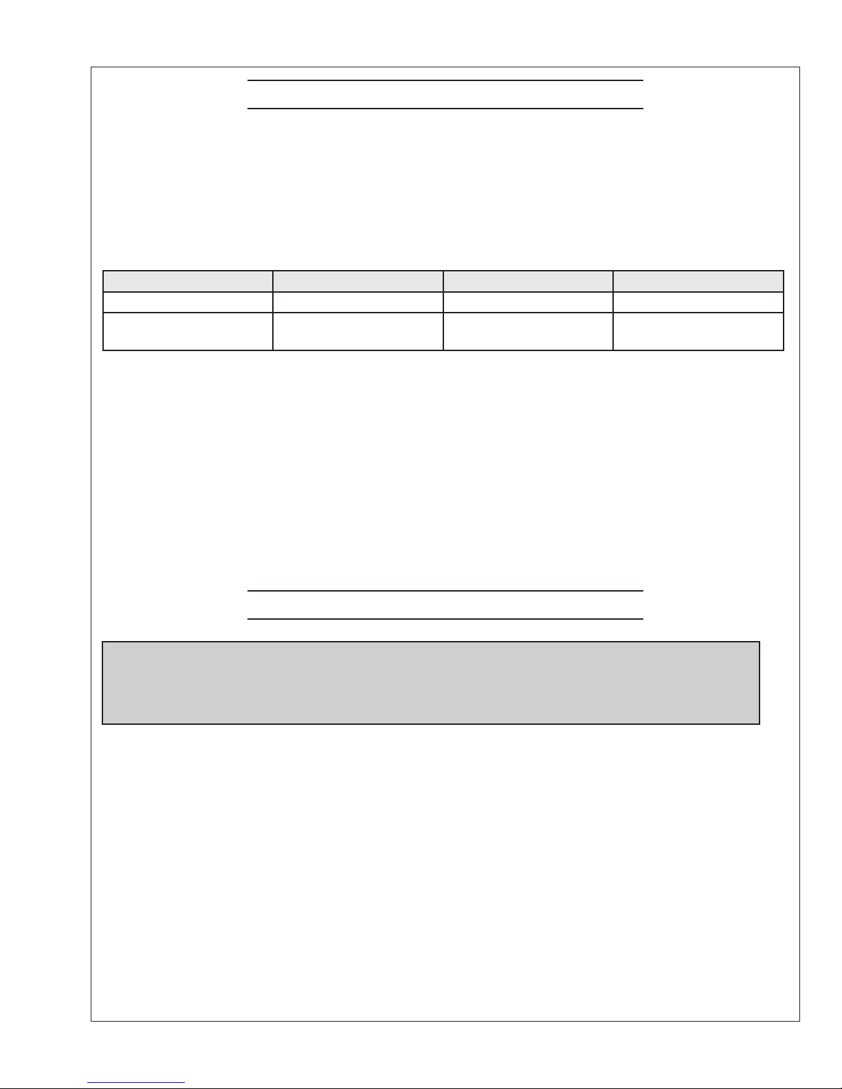
1. GSC300 PRODUCT NUMBER IDENTIFICATION
The GSC300 series catalog order number provides information pertaining to a specifi c model. The
Product Number Identifi cation Table (see Table 1) provides details on the breakdown of the model
number.
Table 1 - IDENTIFICATION TABLE
Position 1-6 Position 8 Position 10-11 Position 13-14
Series Speed Range DC Voltage Labeling
GSC300=GSC300 L=Low
H=High (Consult Factory)
Example: The product number GSC300-L-12-LS would be described as follows:
A GSC300 series automatic engine controller confi gured for a 12 VDC system.
The controller is factory confi gured for low speed range (generator speed range) which includes standard
labeling.
A GSC300 serial number would be displayed as:
GSC300-L-12-LS-00000
12=12 VDC
24=24 VDC
LS=Standard
LX=Customized
2 WIRING INSTALLATION GUIDELINES
Danger: Never work on the engine while its power is on. This controller does
not generate a warning signal prior to automatic engine start. Warning signs should
be placed on engine equipment indicating this important safety measure.
INSTRUCTIONS
Following these instructions will help avoid common installation problems during wiring and setup.
• Battery must be disconnected before any wiring connections are made.
• Wire length from the engine to the controller should not exceed 6 meters (20 feet).
Wiring size and type should be as specifi ed below. Use stranded wire, since solid wire has a tendency to
crack, break and loosen over time.
OGSC300 08/12
1
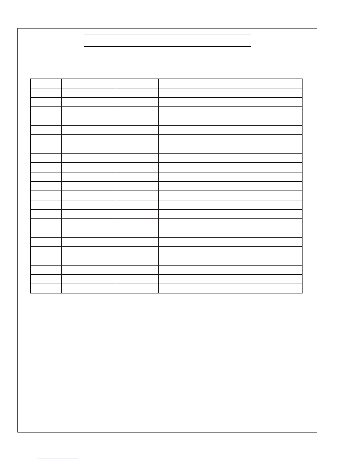
2 WIRING INSTALLATION GUIDELINES (CONTINUED)
Types and Sizes:
Terminal Wire Size (AWG) Current Max Function
1 12 40A Fuel Output Terminal
2 12 40A Auto(Battery +) Terminal Connection
3 12 40A Auto(Battery +) Terminal Connection
4 12 40A Crank Output Terminal
5 12 40A Ground Terminal Connection
6 12 40A Ground Terminal Connection
7 12 40A Preheat/ETS Terminal
8 12 40A Preheat/ETS Terminal
9 18 100mA Speed Signal Connection
10 18 100mA Speed Signal Connection
11 18 300mA Overcrank (failure to start) Output
12 18 300mA Overspeed Output
13 18 300mA High Termp Output
14 18 300mA Low Oil Output
15 18 300mA Low Battery Output
16 18 300mA Engine Run Output
17 18 100mA Not In Auto Output
18 18 300mA General Failure Output
19 18 7ma Start/Stop Input
20 18 7mA Oil Pressure Sender/Switch Input
21 18 7mA Temperature Sender/Switch Input
22 18 7mA Fuel Level/Auxiliary Sender/Switch Input
OGSC300 08/12
2
 Loading...