

Page 1
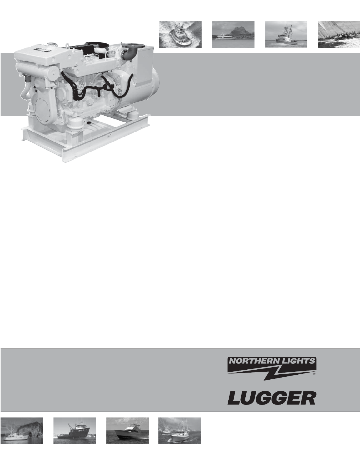
OM2-2
For Models: M1064A, M1064D, M1064T1, M1064T2,
M1066A1, M1066A2, M1066A3, M1066T, M40C2,
M55C2, M65C2, and M99C2
OPERATOR’S MANUAL
Marine Generators | Marine Diesel Engines | Land-Based Generators
Page 2
— CALIFORNIA —
Proposition 65 Warning:
Diesel engine exhaust and some of its constitu-
ents are known to the State of California to cause
cancer, birth defects, and other reproductive harm.
Northern Lights
4420 14th Avenue N.W.
Seattle, WA 98107
Tel: (206) 789-3880
Fax: (206) 782-5455
Copyright ©2010 Northern Lights, Inc.
All rights reserved. Northern Lights™, and
the Northern Lights logo are trademarks of
Northern Lights, Inc.
Printed in U.S.A.
PART NO.: OM2-2 06/10
Page 3
OPERATOR'S MANUAL
#OM2-2 for Models:
M1064A, M1064D, M1064T1, M1064T2, M1066A1, M1066A2,
M1066A3, M1066T, M40C2, M55C2, M65C2, and M99C2
Read this operator's manual thoroughly before starting to operate your equipment.
This manual contains information you will need to run and service your new unit.
Table of Contents
INTRODUCTION ....................................................2
Models Included .................................................2
Model Numbers ..................................................2
Serial Numbers ...................................................2
WARRANTY ............................................................3
SAFETY RULES .....................................................3
COMPONENT LOCATIONS
M1064 .................................................................4
M1066 .................................................................5
M40C2 ................................................................6
ENGINE & GENERATOR CONTROL PANELS
Series 3B & 4B .............................................8 - 9
OPERATING PROCEDURES
Before Starting .................................................10
Shutdown Procedures ...................................... 10
Break-In Period .................................................11
SERVICING SCHEDULE CHARTS .......... 12 - 13
SERVICING
Lubrication - General ....................................... 15
Checking Oil .................................................... 15
Oil Changes ..................................................... 15
Changing Oil Filter .......................................... 15
Air Filter .......................................................... 15
Valve Clearances .............................................. 16
Fuels - General ................................................. 17
Crankshaft Vibration Damper (6 Cyl.) ............ 17
Fuel Filters ............................................... 17 - 18
Bleeding the Fuel System ................................ 18
Injector Service ........................................ 18 - 20
Injection Pump ......................................... 20 - 22
Turbocharger .................................................... 23
Turbo Boost ..................................................... 23
Cooling System - General ................................ 23
Engine Coolant Specifi cations .................23 - 24
Cooling System Flushing ................................. 25
Heat Exchanger Cleaning ................................ 25
Zinc Electrodes ........................................ 25 - 26
Raw Water Pump ............................................. 26
Generator Ends ................................................ 26
Electrical System - General ............................. 26
Booster Batteries .............................................. 27
Battery Care ..................................................... 27
Winterizing / Out-of-Service ........................... 27
TROUBLESHOOTING
Electrical .......................................................... 28
Engine ...................................................... 29 - 30
WIRING DIAGRAMS
AC Wiring ................................................ 31 - 32
DC Wiring ................................................ 33 - 50
ON-BOARD SPARE PARTS .............................. 51
Proprietary Information
This publication is the property of Northern Lights, Inc.
It may not be reproduced in whole or in part without the written permission of Northern Lights, Inc.
© Northern Lights, Inc. All rights reserved. Litho U.S.A. Publication number OM2-2 06/10
OM2-2 06/10
1
Page 4
Introduction
Servicing of marine engines and generator sets
presents unique problems. In many cases boats cannot
be moved to a repair facility. Marine engines cannot
Failures begin with minor problems that are overlooked
and become amplifi ed when not corrected during
routine maintenance.
be compared to the servicing of automobiles, trucks or
even farm equipment. Failures often occur in remote
areas far from competent assistance. Marine engines
are taxed far more severely than auto or truck engines;
therefore, maintenance schedules must be adhered to
more strictly.
As operator, it is your obligation to learn about your
equipment and its proper maintenance. This is not a
comprehensive technical service manual. Nor will it
make the reader into an expert mechanic. Its aim is to
aid you in maintaining your unit properly.
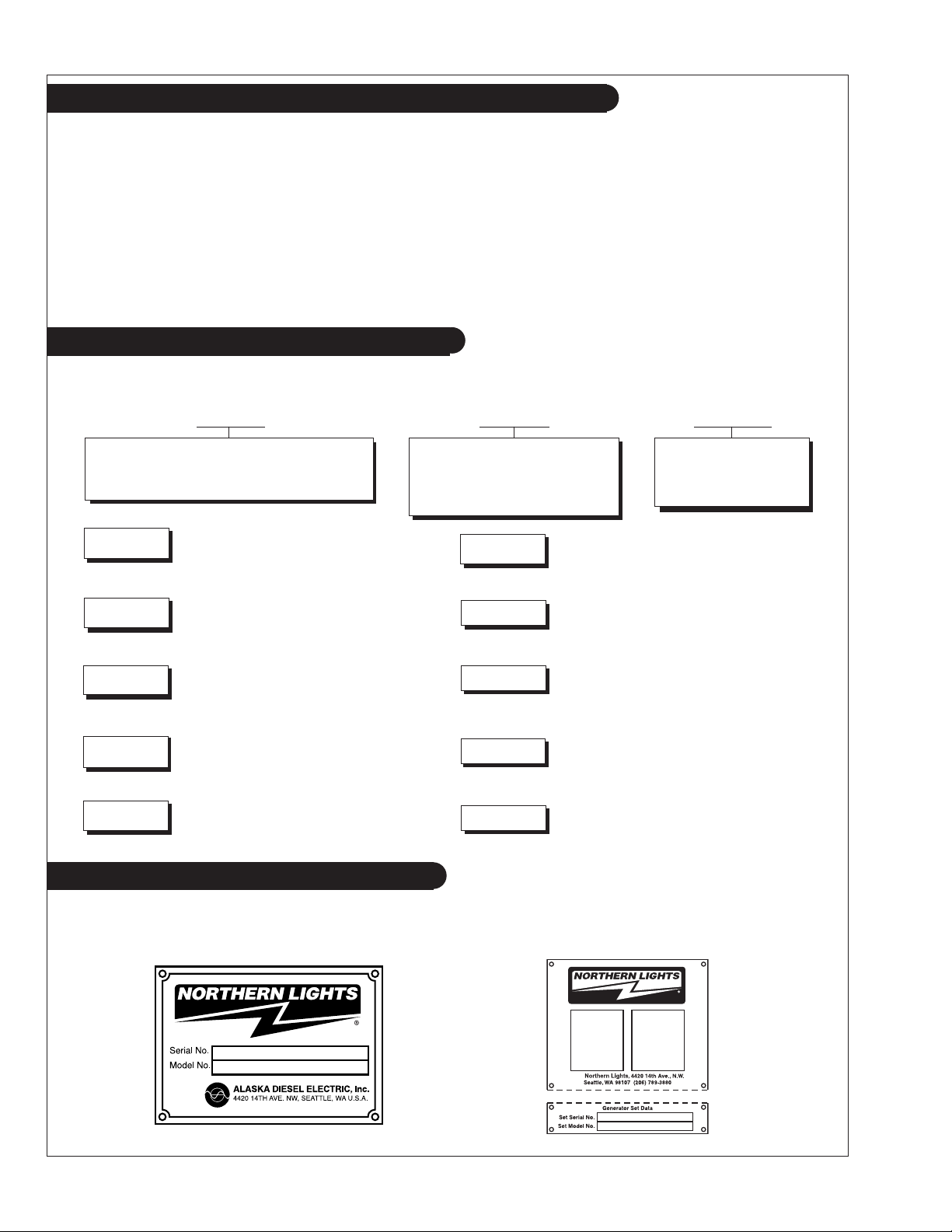
Model Numbers
Model numbers give the unit's application, block model, aspiration, and RPM:
M
M - Northern Lights marine generator set
M1064A
Northern Lights® aftercooled, 1800 RPM
=
marine diesel generator set with a John Deere
Powertech Tier II 4045 engine block with an
electronically controlled fuel system.
106 mm bore, 4 Cylinder
+
or
106 mm bore, 6 Cylinder
1064 or 1066
Model number
M1066T
Northern Lights® turbocharged marine
generator set with a John Deere Powertech
=
Tier II 6068 engine block with an electronically
controlled fuel system.
A, D, & T
A - Aftercooled
D - Naturally aspirated
+
T - Turbocharged
M1064D
M1064T1
M1064T2
M1066A1
Northern Lights® naturally aspirated, 1800
RPM marine diesel generator set with a John
=
Deere Powertech Tier II 4045 engine block
with a mechanically controlled fuel system.
Northern Lights® turbocharged marine
generator set with a John Deere Powertech
=
Tier II 4045 engine block with a mechanically
controlled fuel system.
Northern Lights® turbocharged marine
generator set with a John Deere Powertech
=
Tier II 4045 engine block with an electronically
controlled fuel system.
Northern Lights® aftercooled marine generator
set with a John Deere Powertech Tier II 6068
=
series 1 engine block with an electronically
controlled fuel system
.
MP40C2
MP55C2
MP65C2
MP99C2
40 kW Northern Lights® commercial marine
generator set with a John Deere Powertech
=
Tier II 4045 engine block with a mechanically
controlled fuel system.
55 kW Northern Lights® commercial marine
=
generator set with a John Deere Powertech
Tier II 4045 engine block and a mechanically
controlled fuel system.
65 kW Northern Lights® commercial marine
generator set with a John Deere Powertech
=
Tier II 6068 engine block and an electronically
controlled fuel system.
®
99 kW Northern Lights
=
generator with a John Deere Powertech Tier
II 6068 engine block and an electronically
controlled fuel system.
commercial marine
Serial Numbers
When referencing Northern Lights equipment by serial number, please refer only to the number
stamped on the Northern Lights® serial number plate.
OM2-2 06/10
2
Page 5
Warranty
A warranty registration certifi cate is supplied
with your set. The extent of coverage is described
in the Limited Warranty Statement. We recommend
that you study the statement carefully.
NOTE: If the warranty is to apply, the servicing
instructions outlined in this manual must be
followed. If further information is needed, please
contact an authorized dealer or the factory.
Safety Rules
CAUTION:
You can avoid accidents by observing these safety rules. Study these rules carefully and enforce them on the job.
• Never leave engine without proper security.
• Turn the coolant tank cap slowly to relieve
pressure before removing. Add coolant only
when the engine is stopped and cool.
• Mount a fi re extinguisher near engine.
• Always disconnect the battery ground strap
before making adjustments.
• Operate engines in properly ventilated areas.
• Keep trash and other objects away from engine.
• Escaping fl uids under pressure can penetrate
your skin. Use a piece of cardboard or wood,
not your hands, to search for leaks.
• Avoid wearing loose clothing when working
around engines.
Accident reports show that careless use of engines causes a high percentage of accidents.
• Use caution in handling fuel. Never refuel a hot
or running engine. Do not smoke while fi lling
fuel tank or servicing fuel system.
• Keep your hands, feet, hair and clothing away
from power-driven parts.
• Check for any loose electrical connections or
faulty wiring.
• Engines should be operated only by
knowledgeable, qualifi ed personnel.
• Look completely around engine to make sure
that everything is clear before starting.
• Do not operate an engine that isn't in proper
working order. If an unsafe operating condition is
noted, tag the set and control panel so others will
also know about the problem.
• Do not oil or grease engine while it is running.
• Always disconnect the ECU (Electronic
Control Unit) connectors and remove the ground
connection for the engine control system-tomachine frame before welding on engine. Make
sure no other electronic components are in the
ground path also.
CALIFORNIA
Proposition 65 Warning:
Diesel engine exhaust and some of its constitu-
ents are known to the State of California to cause
cancer, birth defects, and other reproductive harm.
• Provide fi rst aid kits.
CAUTION: This symbol is used throughout
this book to alert you to possible danger areas.
Please take special notice of these sections.
OM2-2 06/10
3
Page 6
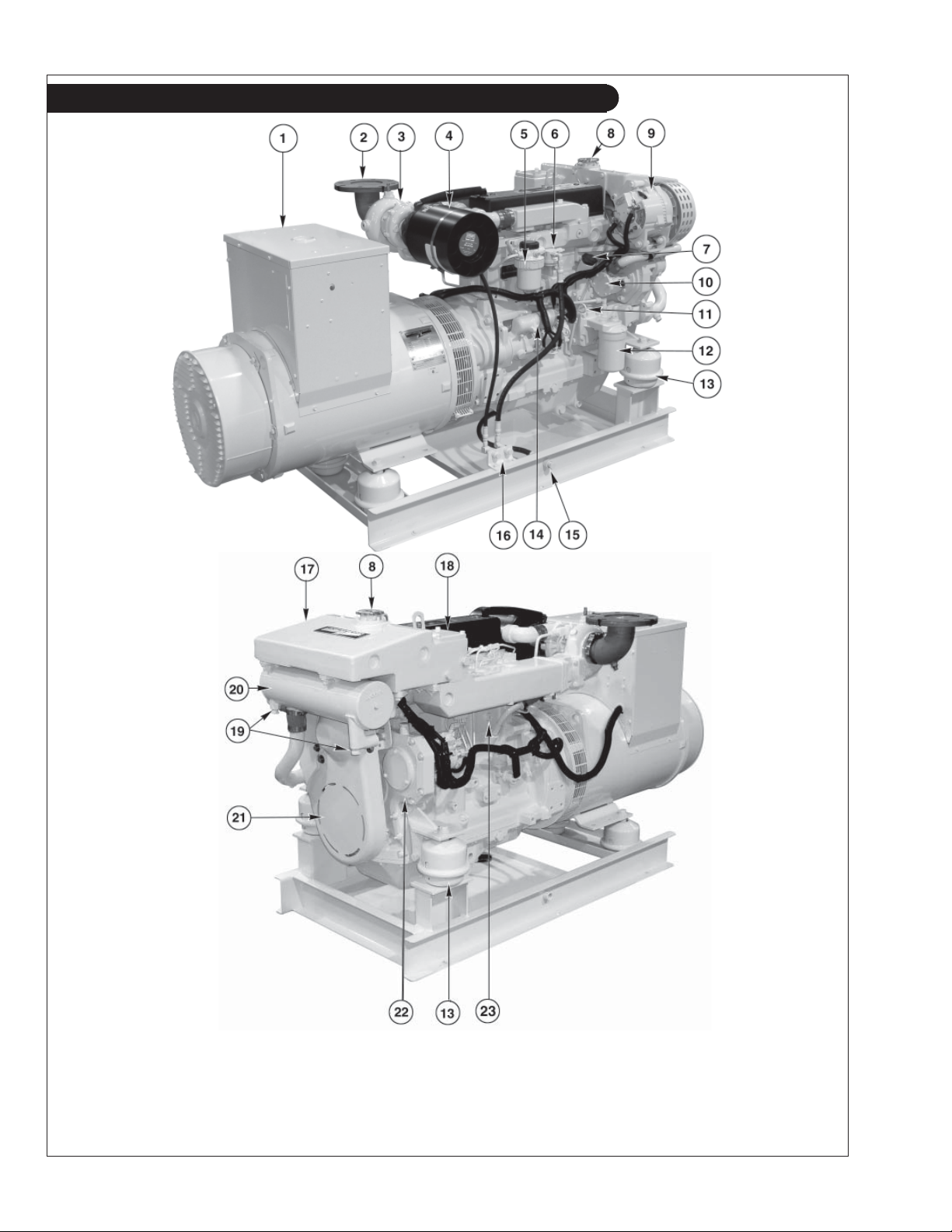
Component Locations
Figures 1 & 2: M1064T1
(Mechanically Controlled Fuel System)
1. Junction Box
2. Exhaust Elbow
3. Turbocharger
4. Air Cleaner
5. Fuel Filter
6. Fuel Lift Pump
7. Lube Oil Fill
8. Coolant Fill
9. Alternator
10. Raw Water Pump
11. Lube Oil Dipstick
12. Lube Oil Filter
13. Optional Hydrolastic Mount
14. Starter
15. Lube Oil Drain
16. Fuel Manifold
17. Expansion Tank
18. Thermostat Cover
19. Heat Exchanger Zincs
20. Heat Exchanger
21. Belt Guard
OM2-2 06/10
4
22. Injection Pump Drive
Coupling Access Cover
Plate
23. Engine Block Drain
Page 7
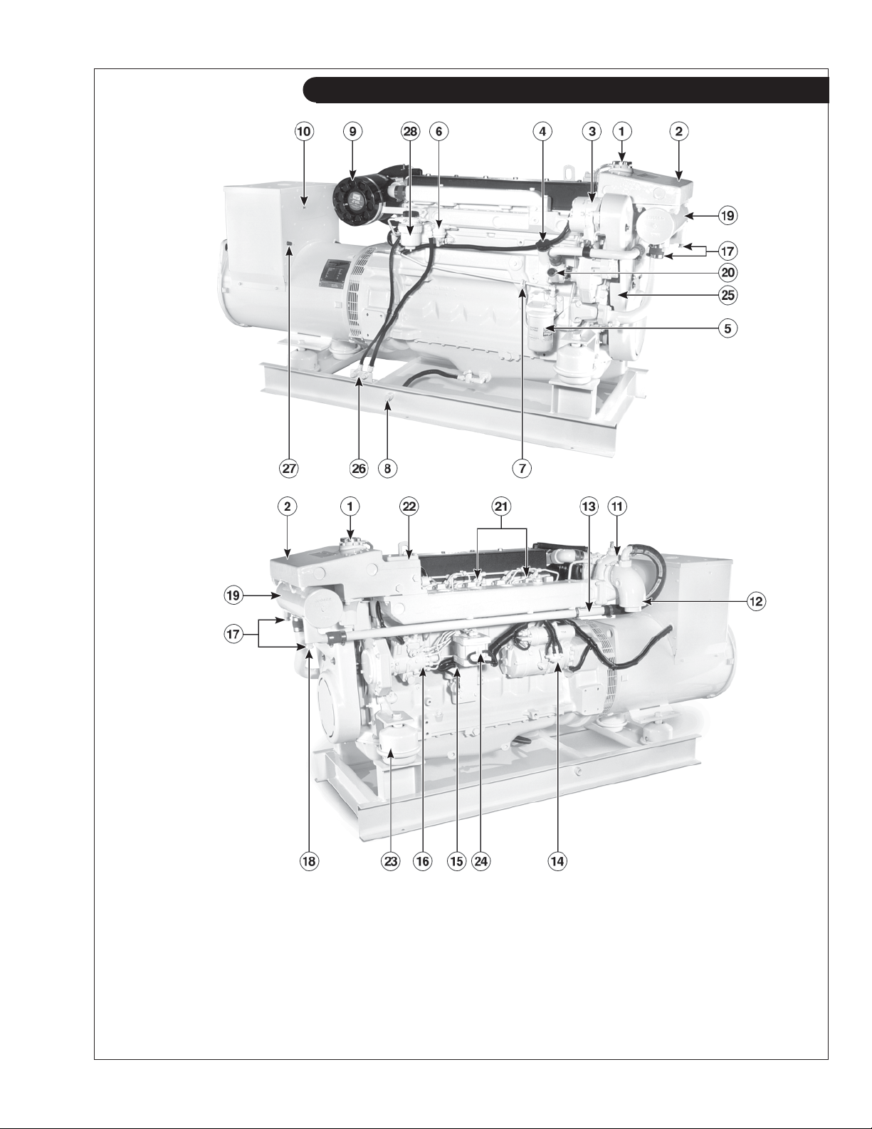
Component Locations
Figure 3 & 4: M1066T (Mechanically Controlled Fuel System)
1. Coolant Fill
2. Expansion Tank
3. DC Alternator
4. Lube Oil Fill
5. Lube Oil Filter
6. Fuel Lift Pump
7. Lube Oil Dipstick
8. Lube Oil Drain
9. Air Cleaner
10. DC Circuit Breaker
11. Turbocharger
12. Wet Exhaust Elbow
13. Exhaust Manifold Drain
14. Electric Starter
15. Engine Block Drain
16. Fuel Injection Pump
OM2-2 06/10
17. Heat Exchanger Zinc (2)
18. Heat Exchanger Drain
19. Heat Exchanger
20. Raw Water Pump
21. Fuel Injectors (6)
22. Thermostat cover
23. Optional Hydrolastic
Mounts
5
24. Optional Governor Actuator
25. Drive Belt Cover
26. Fuel Manifold
27. A.V.R. Fuse
28. Fuel Filter
Page 8
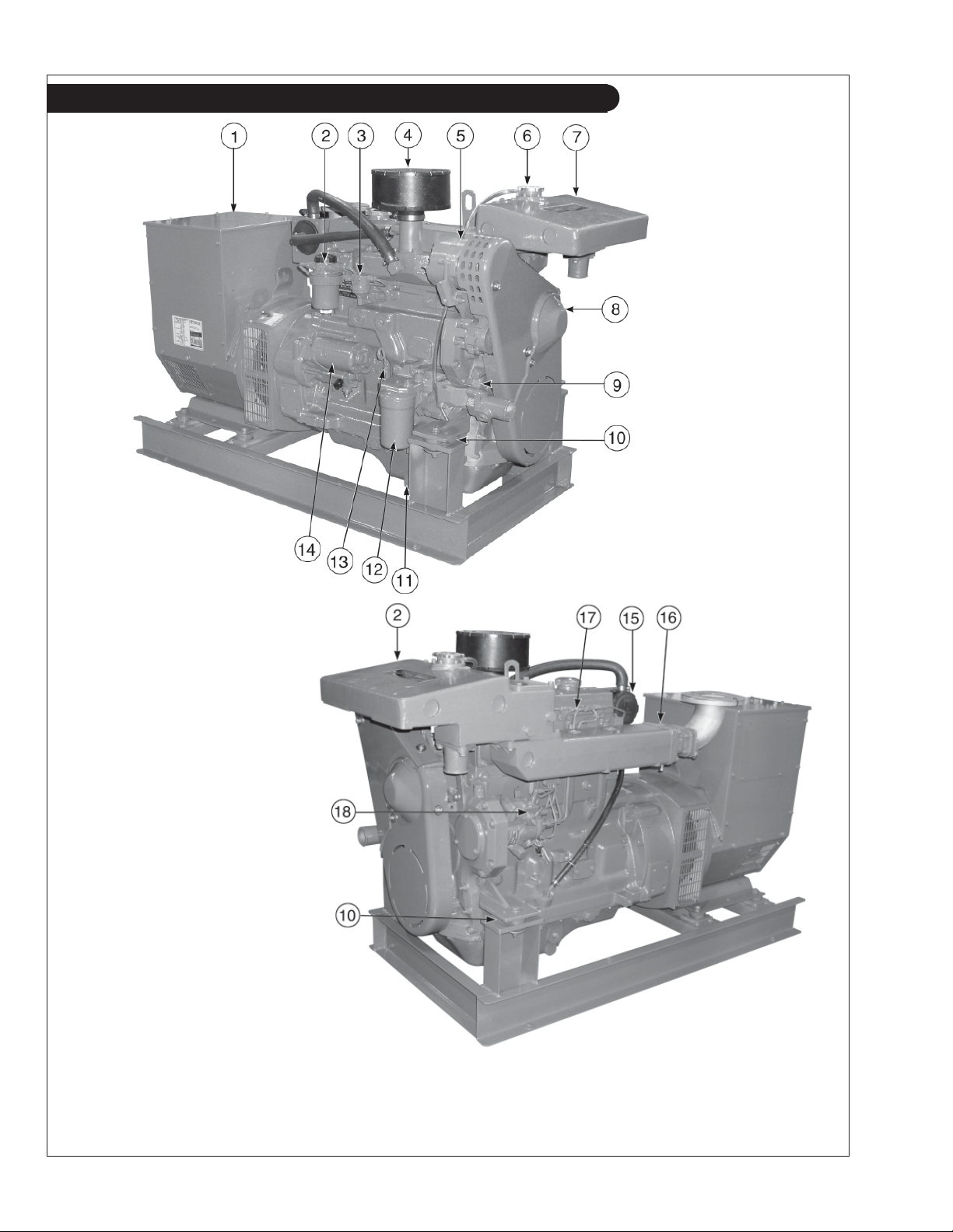
Component Locations
Figure 5 & 6: M40C2 (Mechanically Controlled Fuel System)
1. Junction Box
2. Fuel Filter
3. Fuel Lift Pump
4. Air Cleaner
5. Alternator
6. Coolant Fill
7. Expansion Tank
8. Belt Guard
9. Coolant Pump
10. Centerbonded Mounts
11. Lube Oil Drain
12. Lube Oil Filter
13. Dipstick
14. Electric Starter
15. Closed Crankcase Vent
OM2-2 06/10
16. Exhaust Manifold
17. Injection Lines
18. Fuel Injection Pump
6
Page 9
Notes
OM2-2 06/10
7
Page 10
Northern Lights Control Panels
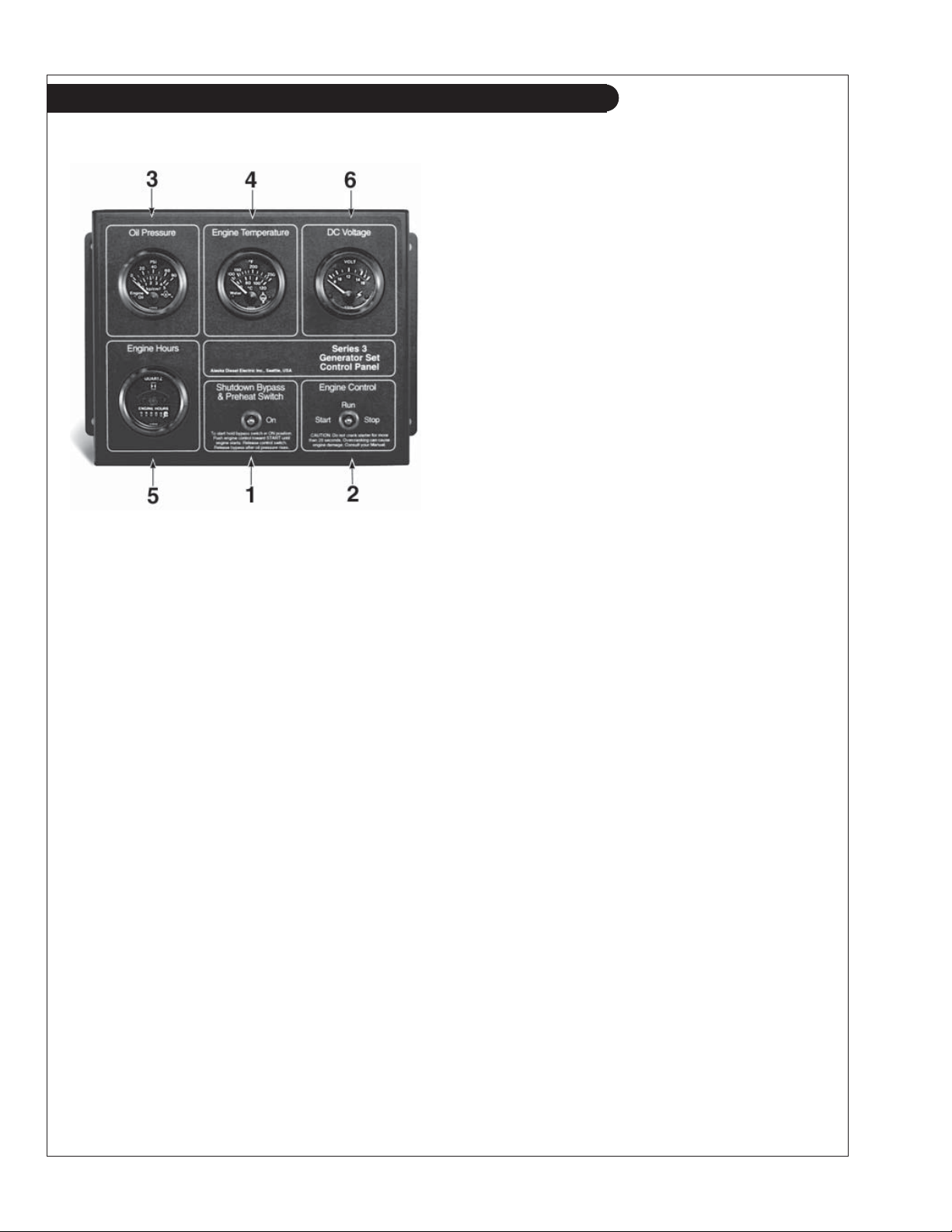
Figure 7: Series 3B Generator Control Panel
1. SHUTDOWN BYPASS SWITCH
This switch bypasses the safety shutdown feature
during the starting process.
2. ENGINE CONTROL SWITCH
To start the engine, hold this switch in the START
position until the engine is running.
NOTE: Excessive cranking of marine sets equipped
with water lift muffl er systems can cause engine
damage.
After the engine starts, release the switch and it will
return to RUN position. To stop the engine, hold
the switch in the STOP position.
3. OIL PRESSURE GAUGE
The oil pressure gauge shows the oil pressure in
the engine lubricating system. If the pressure drops
below 15 PSI at a speed higher than idling, stop the
engine and investigate.
4. COOLANT TEMPERATURE GAUGE
Water temperature gauge shows the temperature of
the cooling water. If the gauge registers over 200°F
(93.30C) or drops below 140°F (600C), stop the
engine and investigate.
5. HOUR METER
Keeps track of the engine running time.
6. DC VOLTMETER
When the engine is running, it indicates the
voltage output of the alternator.
OM2-2 06/10
8
Page 11
Northern Lights Control Panel
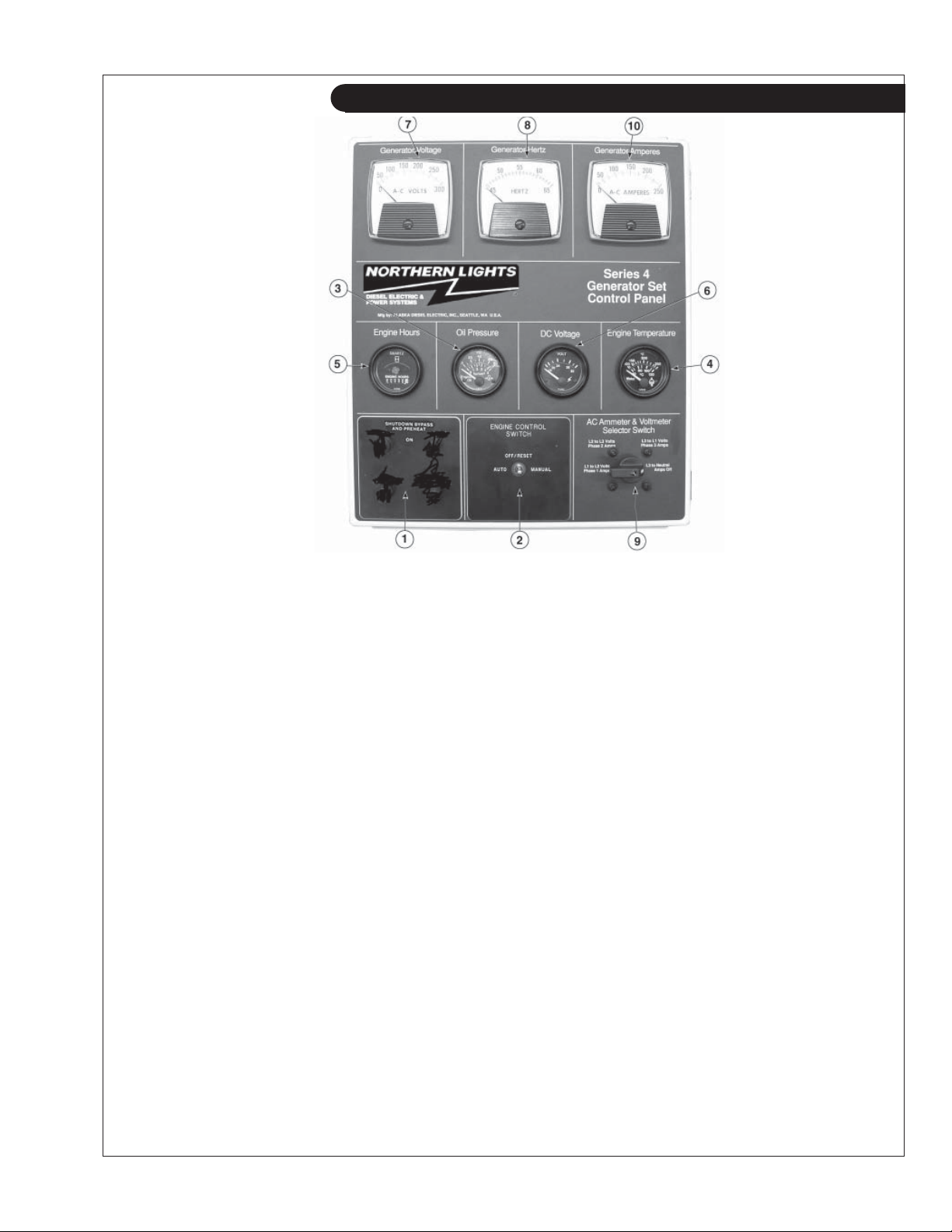
Figure 8: Series 4 B Generator Control Panel
1. SHUTDOWN BYPASS SWITCH
This switch bypasses the safety shutdown feature
during the starting process.
2. ENGINE CONTROL SWITCH
The control switch starts and stops the engine.
3. OIL PRESSURE GAUGE
The oil pressure gauge shows the oil pressure in
the engine lubricating system. If the pressure drops
below 15 PSI at a speed higher than idling, stop the
engine and investigate.
4. COOLANT TEMPERATURE GAUGE
Water temperature gauge shows the temperature of
the cooling water. If the gauge registers over 200°
(93.30C) or drops below 140°(600C), stop the engine
and investigate.
5. HOUR METER
Keeps track of the engine running time.
6. DC VOLTMETER
When the engine is running, it indicates the voltage
output of the alternator.
7. AC VOLTMETER
The voltmeter shows the generator output
voltage, phase to phase. If the voltage
fl uctuates greatly from the normal reading, shut
down the unit and investigate.
8. FREQUENCY METER
Indicates engine speed. The correct reading for
1800 and 1200 RPM sets is 60 Hz. For 1500 RPM
sets, it is 50 Hz. If meter does not indicate correct
hertz, stop and investigate.
9. AMMETER SELECTOR SWITCH
The ammeter switch is used for checking each
phase for load condition. Leave it in the ON
position while the engine is running.
10. AC AMMETER
The ammeter indicates the phase load. Check for
load unbalance. If the unbalance is greater than
30%, have an electrician balance the load properly.
This will ensure longer generator life and better
economy.
OM2-2 06/10
9
Page 12
Operating Procedures
BEFORE STARTING
1. Check the water level by removing the pressure
cap from the expansion tank. In order to give the
cooling water room to expand, the level should be
about 1 3/4 in. (4-5 cm) below the fi ller cap sealing
surface when the engine is cold. When fi lling with
coolant, the venting cock on top of the turbocharger
should be opened to ensure that no air pockets form
in the cooling system (see Service Point #14).
CAUTION: Use protective clothing and open
the fi ller cap carefully when the engine is warm
to prevent burns.
2. Check the oil level in the crankcase with the dipstick.
The oil level should be between the “waffl ed area”
and the “oo”. Never allow the level to go below
the “oo”. Always add the same viscosity of oil as is
already in the crankcase (see Service Point #1).
3. Check the fuel tank level and open any fuel valves.
4. Disengage clutch, if equipped.
5. Close the seacock, check and clean the strainer and
reopen the seacock.
6. Place the battery switch in the ON position.
NOTE: The battery switch must always be kept ON
while the engine is running. If the switch is turned
OFF while the engine is running, the battery charging
regulator could be ruined.
Starting
1. While holding the Shutdown Bypass switch in the
ON position, push the Engine Control switch to the
START position.
2. As soon as the engine starts, release both switches.
Do not crank the starter for more than 20 seconds.
3. If the engine fails to start the fi rst time, be sure the
starter has stopped before re-engaging.
NOTE: If there is a governor locked at a specifi c
speed on the generator set, there may not be a slow
idle function, so in that case operate the engine at
high idle for 1 to 2 minutes before adding load. If
the stand-by generator set is loaded as soon as it
reaches rated speed, this procedure would not apply.
Operating
1. Check Gauges Often: Oil pressure must be above
29 PSI (if not above 15 PSI within 5 seconds of
starting, the engine should be stopped and the
problem should be explored). Normal oil pressure
is 50 PSI at rated load speed (1800 to 2500 RPM).
Oil temperature should be 1150C (2400F) for normal
operating temperature. The D.C. voltmeter should
read between 13 and 14 volts (26-28 volts, 24 volt
systems).
2. Check AC voltage and frequency meters (Series 4
Panel). If gauges deviate from normal levels, shut
down the set and investigate.
3. Check belt for good alignment.
4. Let the unit run unloaded for a three to fi ve minute
warm-up period before applying load.
5. Do not add full electrical load until engine is at
maximum operating temperature.
Shutdown
1. Turn the Engine Control Switch to the OFF
position.
2. Close the sea cock and fuel valves, and put the
battery switch in the OFF position if the unit will be
off for an extended period.
NOTE: Do not turn the battery switch to OFF while
the engine is running.
SHUTDOWNS AND ALARMS
1. Your unit is fi tted with a system to protect it from
high water temperature or low oil pressure.
a. Generator sets have shutdown systems to stop
the engine. They have no warning horns.
b. Other alarms and shutdowns are available as
optional equipment.
NOTE: Do not rely on your warning or shutdown
system to the exclusion of careful gauge monitoring.
Watching your gauges can prevent damage to the unit
and dangerous power losses.
2. Do the following when your shutdown system is
activated:
a. Check the temperature gauge. If the temperature
is above 205°F (97°C), shut off the engine
immediately.
b. Use the Trouble Shooting Guide on pages 26- 28
to isolate the cause of the overheat.
OM2-2 06/10
10
Page 13
CAUTION: Do not remove the water fi ll cap of
an overheated engine. Escaping high
temperature steam can cause severe burns.
Allow the engine to cool and then remove the
cap slowly, using protective clothing.
c. Make repairs and restart after the temperature
gauge registers below 180°F (83°C).
d. Watch the temperature gauge regularly and
turn off the unit if the temperature rises above
200°F (93.3°C). Repeat the troubleshooting
process.
3. If the shutdown is activated and the temperature
gauge shows temperature within normal temperature
range:
a. Check the engine crankcase oil level.
b.
If the oil level is low, fi ll with recommended
lubricating oil and restart. Watch the oil pressure
gauge carefully and shut off the engine if it does
not show a normal reading after a few seconds of
operation.
c. If the oil level was normal, DO NOT restart the
engine. Call your Northern Lights or Lugger
dealer for assistance.
Operating Procedures
3. Oil consumption is greater during break-in as piston
rings take time to seat.
4. Your engine comes equipped with break-in oil.
Change engine oil and fi lter at 50 hours using API
Service Category CC, CD, or CE break-in oil.
Change the oil and fi lter again at 100 hours.
(Consult the lubricants section for oil
recommendation.)
5. Frequently check the engine temperature and oil
pressure gauges.
BREAK-IN PERIOD
1. Your engine is ready to be put into service. However, the fi rst 100 hours on a new or reconditioned
engine are critical to its life and performance. This
is especially true of an engine that runs at a constant
speed such as a generator engine.
2. Operate with an average of 75% load on your engine
for the fi rst 100 hours. Maintain no less than a 50%
load to ensure proper seating of the piston rings.
OM2-2 06/10
11
Page 14
Revised 9-23-10
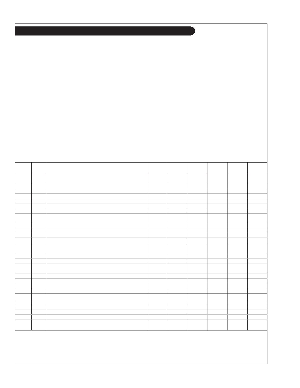
Service Schedule Chart, Mechanically Controlled Fuel System
The Servicing Schedule Chart below shows the service schedule required for proper maintenance of your marine generator
set. More detailed coverage of each Service Point (SP) is listed on the page noted in the ‘page’ column.
DAILY:
SP1 Check oil level in engine
SP8 Check primary fuel fi lter
SP15 Check cooling water level
SP26 Check crankcase vent system fi lter svc. indicator button
AFTER FIRST 50 HOURS:
SP2 Change engine oil
SP3 Change lube oil fi lter
EVERY 50 HOURS:
SP21 Check electrolyte in batteries
FIRST 100 HOURS:
SP2 Change engine oil
SP3 Change lube oil fi lter
EVERY 100 HOURS:
SP13 Check turbocharger air, oil & cooling lines for leakage
EVERY 250 HOURS:
SP2 Change engine oil
SP3 Change lube oil fi lter
SP4 Check air cleaner
SP9 Change primary fuel fi lter element
SERVICE 50 100 250 500 2000
POINT PAGE OPERATION DAILY Hours Hours Hours Hours Hours
ENGINE:
SP1 15 Check oil level •
SP2 15 Change engine oil 2) 1) 1) •
SP3 15 Change lube oil fi lters 2) 1) 1) •
SP4 15 Check (replace) air cleaner 2) 4) • •
SP5 Check belt condition 2) •
SP6 16 Check valve clearances 2) • •
SP7 17 Check crankshaft vibration damper •
SP13 Check turbocharger air, oil & cooling lines for leakage
SP19 Check zinc electrodes
SP23 Test thermostats
AFTER FIRST 500 HOURS:
SP6 Check valve clearances
EVERY 500 HOURS / YEARLY:
SP4 Replace air cleaner
SP5 Check belt condition
SP7 Check crankshaft vibration damper
SP10 Change secondary fuel fi lter
SP11 Check injectors
SP14 Check turbocharger boost pressure
SP16 Check cooling system
SP20 Change impeller in raw water pump
SP22 Check the state of the charge of the batteries
SP26 Check crankcase vent system, change element at 500 hrs.
EVERY 2000 HOURS:
SP6 Check valve clearances, adjust if necessary
SP12 Check fuel injection pump
SP17 Check and clean heat exchanger
FUEL SYSTEM:
SP8 17 Check primary fi lter (Racor) 3) •
SP9 17 Change primary fi lter element (Racor) 3) 4) •
SP10 17 Change secondary fuel fi lter 2) 4) •
SP11 18-19 Check injectors 2) •
SP12 20-22 Check fuel injection pump •
TURBOCHARGER:
SP13 23
SP14 23 Check boost pressure •
SP26 27 Check crankcase vent system
SP15 25 Check cooling water level •
SP16 25 Check and fl ush cooling system 2) • 5)
SP17 25 Check and clean heat exchanger 2) •
SP19 25-26 Check zinc electrodes 2) 4) •
SP20 26 Change impeller in raw water pump 2) 4) •
ELECTRICAL SYSTEM:
SP21 27 Check electrolyte level in batteries 2) 4) •
SP22 27 Check condition of batteries with hydrometer 2) •
SP23 Test thermostats •
Check air, oil & cooling water lines for leakage
COOLING SYSTEM:
2)
•
2)
• 6)
1) Change the oil and fi lter at 50 hours, using break-in oil again, until changing it
at 100 hours, then at every 250 hours.
2) Perform all maintenance once a year even if hour level has not been reached.
3) Consult manufacturer's maintenance schedule.
OM2-2 06/10
12
4) Or whenever necessary.
5) Check the cooling system at 500 hours, fl ush at 2000 hours.
6) Check hoses and o-rings, replace element at 500 hours.
Page 15
Revised 9-23-10
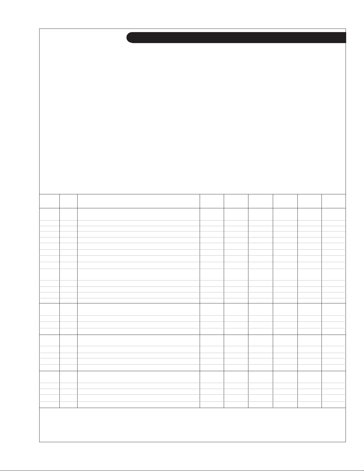
Service Schedule Chart, Electronically Controlled Fuel System
The Servicing Schedule Chart below shows the service schedule required for proper maintenance of your marine
generator set. More detailed coverage of each Service Point (SP) is listed on the page noted in the ‘page’ column.
DAILY:
SP1 Check oil level in engine
SP8 Check primary fuel fi lter
SP15 Check cooling water level
SP26 Check crankcase vent system fi lter svc. indicator button
AFTER FIRST 50 HOURS:
SP2 Change engine oil
SP3 Change lube oil fi lter
EVERY 50 HOURS:
SP21 Check electrolyte in batteries
AFTER FIRST 100 HOURS/ EVERY TWO WEEKS 5:
SP2 Change engine oil after fi rst 100 hrs., then check every 2 wks.
SP3 Change oil fi lter after fi rst 100 hrs., then check every 2 wks.
SP7 Check crankshaft vibration damper
SP15 Check coolant level
EVERY 250 HOURS :
SP2 Change engine oil
SP3 Change lube oil fi lter
SP4 Check air cleaner
SP19 Check zincs
SERVICE 50 100 250 500 2000
POINT PAGE OPERATION DAILY Hours Hours Hours Hours Hours
ENGINE:
SP1 15 Check oil level •
SP2 15 Change engine oil 2) 1) 1) •
SP3 15 Change lube oil fi lters 2) 1) 1) •
SP4 15 Check air cleaner • •
SP5 Check belt condition 2) •
SP6 16 Check valve clearances 2) •
SP7 17 Check crankshaft vibration damper 5) •
7
SP25 Check engine mounts •
SP27 Check air intake hoses •
FUEL SYSTEM:
SP8 17 Check primary fi lter (Racor) 3) •
SP9 17 Change primary fi lter element (Racor) 3) 4) •
SP10 17 Change secondary fuel fi lter 2) 4) •
SP11 18-19 Check injectors 2)
SP12 20-22 Check fuel injection pump •
TURBOCHARGER:
SP13 23
SP14 23 Check boost pressure •
SP30 27 Check aftercooler, clean air side •
SP26 27 Check crankcase vent system
Check air, oil & cooling water lines for leakage
2)
2)
COOLING SYSTEM:
SP15 25 Check cooling water level •
SP16 25 Check and fl ush cooling system 2) 6) •
SP17 25 Check and clean heat exchanger 2) •
SP19 25-26 Check zinc electrodes 2) 4) •
SP20 26 Change impeller in raw water pump 2) 4) •
ELECTRICAL SYSTEM:
SP21 27 Check electrolyte level in batteries 2) 4) •
SP22 27 Check condition of batteries with hydrometer 2) •
SP23 Test thermostats •
SP29 Check electrical ground connection •
EVERY 500 HOURS / YEARLY:
SP4 Replace air cleaner
SP5 Check belt condition
SP9 Change primary fi lter element (Racor)
SP10 Change secondary fuel fi lter
SP11 Check injectors
SP14 Check turbocharger boost pressure
SP16 Check cooling system
SP20 Change impeller in raw water pump
SP22 Check the state of the charge of the batteries
SP25 Check engine mounts
SP26 Check crankcase vent system, change element at 500 hrs.
SP27 Check air intake hoses
SP29 Check electrical ground connection
EVERY 2000 HOURS:
SP6 Check & adjust valve clearance
SP7 Check crankshaft vibration damper
SP12 Check fuel injection pump
SP16 Flush cooling system
SP17 Check and clean heat exchanger
SP23 Test thermostats
SP30 Check aftercooler, clean air side
•
•
• 7)
1) Change the oil and fi lter at 50 hours, using break-in oil again, until changing it
at 100 hours, then at every 250 hours.
2) Perform all maintenance once a year even if hour level has not been reached.
3) Consult manufacturer's maintenance schedule.
4) Or whenever necessary.
OM2-2 06/10
13
5) Replace damper every 4500 hours or after 60 months.
6) Check cooling system at 500 hours, fl ush at 2000 hours.
7) Check hoses, and o-rings on crankcase vent system, change
element at 500 hours.
Page 16
Notes
OM2-2 06/10
14
Page 17
updated 6-7-10
Servicing
LUBRICATION
Break-in oil
1. Use one of the following during the fi rst 100 hours
of operation:
a. John Deere Engine Break-In Oil
b. API Service Category CC, CD, or CE oil
c. ACEA Specifi cation E1
2. Do not use John Deere PLUS-50 oil or engine oils
meeting API CG4, API CF4, ACEA E3, or ACEA
E2 performance levels during the fi rst 100 hours of
operation of a new or rebuilt engine. These oils will
not allow the engine to break-in properly.
Lubrication - General
1. Use only clean, high quality lubricants stored in
clean containers in a protected area.
2. These oils are acceptable after the fi rst 100 hours:
a. ACEA Oil Sequence E5 and E4
b. API Service Category CI-4 or CH-4.
c. ACEA Oil Sequence E3 multi-viscosity oil.
3. Use the proper weight oil for your average operation
temperature.
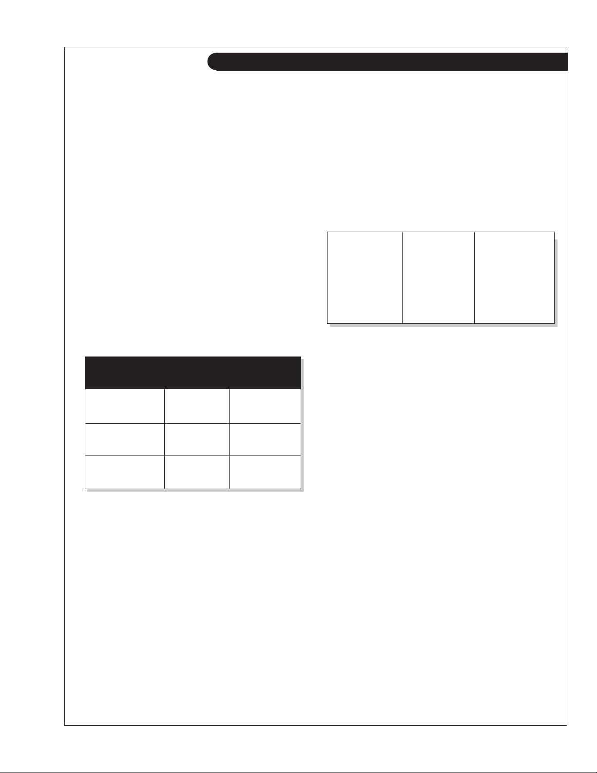
Air Single Multi
Temperature Viscosity Viscosity
Above 32°F
(0°C)
-10°F to 32°F
(-23°C to 0°C)
SAE-30W SAE15-40W
SAE-10W SAE10-30W
Below -10°F
(-23°C)
SAE-5W SAE5-20W
4. Some increase in oil consumption may be expected
when SAE 5W and SAE 5-20W oils are used. Check
oil level frequently.
5. Never put additives or fl ushing oil in crankcase.
SP1. CHECK ENGINE OIL LEVEL
1. Check the oil level in the crankcase, with the oil
dipstick, daily.
2. The oil level must be between the “Waffl ed area” and
the “oo”. Never allow the level to go below the “oo”.
3. Always add the same viscosity of oil as is already in
the crankcase.
SP2. OIL CHANGES
1. Using the oil recommended above, change the
engine oil and fi lter after the fi rst 50 hours of opera-
tion, the fi rst 100 hours and every 250 hours thereaf-
ter.
SP2. OIL CHANGES continued
2. During intermittent cold weather operation, change oil
every 100 hours or six weeks, whichever comes fi rst.
3. Change oil at any seasonal change in temperature when
a new viscosity of oil is required.
a. Remove plug from outlet in base frame. Screw in
owner-supplied drain hose.
b. Open valve at oil pan outlet. After oil has been
drained into suitable container, close valve, remove
drain hose and replace plug in base frame outlet.
c. Refi ll engine with recommended oil.
4. Engine Lube Oil Capacity:
M1064D & T1 15.5 qts. 14.7 liters
M1064T2
M1064T2
M1064A & H 21.6 qts. 20.5 liters
M40C2 15.5 qts. 14.7 liters
M55C2 15.5 qts. 14.7 liters
M65C2 15.5 qts. 14.7 liters
M1066T 20.0 qts. 19.0 liters*
M1066A1, A2, A3 34.3 qts. 32.5 liters
M99C2 20.0 qts. 19.0 liters
*depending on oil pan size
(@60 Hz)
(@50 Hz)
15.5 qts. 14.7 liters
21.6 qts. 20.5 liters
SP3. CHANGING OIL FILTER
1. Change the lube oil fi lter every 250 hours, after the
initial 50 and 100 hour change.
2. Use a fi lter wrench to remove old fi lter. Dispose of fi lter
in approved manner.
3. Make sure the gasket from the old fi lter is removed and
discarded.
4. Lubricate the rubber gasket on the new fi lter and screw it
on nipple until gasket meet the sealing surface.
5.
Using hands only, no wrench, tighten fi lter one-half turn
farther. Overtightening can do damage to fi lter housing.
6. Fill engine with recommended oil. Start engine and
check for leakage. Stop engine and check oil level. Add
additional oil if necessary.
SP4. AIR CLEANER
1. Inspect air cleaner every 100 hours. Replace fi lter every
500 hours, or yearly, whichever comes fi rst for
mechanically controlled fuel system engines. For elec-
tronically controlled units - replace air cleaner element
every 500 hours.
2. Clean the rubber tube at the cleaner. Loosen the hose
clamp and the attaching strip for the cleaner.
3. Make sure the rubber tube is in good condition and that
new fi lter is absolutely clean and installed properly.
4. Start the engine and check for leaks.
NOTE: Make absolutely sure no impurities enter the
engine while changing the element. Do not run the engine
with the air cleaner removed.
OM2-2 06/10
15
Page 18
Servicing
SP6. VALVE CLEARANCES
The following special tools will be needed:
JDE 820 or JDE 83 Flywheel Turning Tool,
JDE 81-4 Timing Pin.
1. Remove rocker arm cover with ventilator tube.
2. Remove plastic plugs in engine timing holes on front
side of fl ywheel.
3. Rotate fl ywheel in clockwise direction (viewed from
water pump) with the Flywheel Turning Tool until
the Timing Pin engages timing hole in the fl ywheel.
Both rocker arms for No. 1 cylinder will be loose at
Top Dead Center. If they are not, remove the timing
pin and rotate the fl ywheel one complete turn and
reinstall the timing pin in the fl ywheel.
4. Valve clearances must be checked with the engine
cold.
Intake Valve: 0.012-0.015 in. (0.31-0.38 mm)
Exhaust Valve: 0.016-0.019 in. (0.41-0.48 mm)
5. If the valves need adjusting, loosen the jam nut (A
on Figure 9)
on the rocker arm adjusting screw. Turn
the adjusting screw until you feel a slight drag when
the feeler gauge slips. With a screwdriver, hold the
adjusting screw from turning while tightening the
jam nut to specifi cations. Check the clearance again
after tightening the jam nut. Re-adjust as needed.
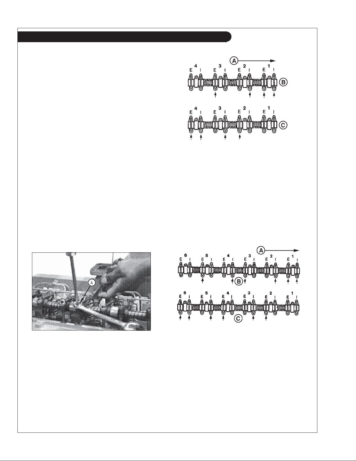
NOTE: Firing order is 1 - 3 - 4 - 2
Reproduced by permission of Deere & Company, c2004. Deere & Company.
All rights reserved. RG4776 Figure 10
A - Front of Engine
B - No. 1 Piston at TDC Compression Stroke
C - No. 4 Piston at TDC Compression Stroke
E - Exhaust Valve
I - Intake Valve
Adjust valve clearance on No. 2 and No. 4 exhaust
valves and No. 3 and No. 4 intake valves.
6-CYLINDER ENGINES:
NOTE: Firing order is 1 - 5 - 3 - 6 - 2 - 4
Reproduced by permission of Deere & Company, c2004. Deere & Company. All rights reserved. RG7409
Figure 9
4-CYLINDER ENGINES:
Lock No. 1 piston at TDC compression stroke
(B).
Adjust valve clearance on No. 1 and No. 3
exhaust valves and No. 1 and No. 2 intake
valves.
Rotate fl ywheel 360°. Lock No. 4 piston at
TDC compression stroke (C).
Reproduced by permission of Deere & Company, c2004. Deere & Company. All rights
reserved. RG4777 Figure 11
A - Front of Engine
B - No. 1 Piston at TDC Compression Stroke
C - No. 6 Piston at TDC Compression Stroke
E - Exhaust Valve
I - Intake Valve
Lock No. 1 piston at TDC compression stroke (B).
Adjust valve clearance on No. 1, No. 3, and No. 5 exhaust
valves and No. 1, No. 2, and No. 4 intake valves.
Rotate fl ywheel 360°. Lock No. 6 piston at TDC
compression stroke (C). Adjust valve clearance on No. 2,
No. 4, and No. 6 exhaust valves and No. 3, No. 5, and No.
6 intake valves.
OM2-2 06/10
16
Page 19
Servicing
FUELS - GENERAL
1. Use only clean, high quality fuels of the following
specifi cations, as defi ned by ASTM designation D975 for
diesel fuels:
a. Use Grade No. 2 diesel at ambient temperatures
above freezing 30°F (0°C).
b. Use Grade No.1 at ambient temperatures below
freezing and for all temperatures at an altitude of
above 5,500 ft. (1500 meters).
2. Sulphur content should not exceed 0.5% (preferably less
than 0.5%).
3. The cetane number should be a minimum of 45.
4. DO NOT use these unsuitable grades of fuel:
a. Domestic heating oils, all types, b. Class B engine,
c. Class D domestic fuels, d. Class E, F, G or H industrial
or marine fuels,
e. ASTM-D975-60T No. 4-D and higher
number fuels, f. JP4
5. Storing fuel:
a. Keep dirt, scale, water and other foreign matter
out of fuel.
b. Avoid storing fuel for long periods of time.
c. Fill the fuel tank at the end of each day's operation. This
will reduce condensation.
6. Biodiesel:
Biodiesel involves the transesterifi cation of vegetable oils or animal fats.
Mainly in the U.S. soybean methyl ester is used (SME), but in Europe
mainly rapeseed (canola) methyl ester is made (RME), and in Asia palm
methyl ester is made (PME). 100% biodiesel (B100) is made in compli-
ance with ASTM D6751 or EN14214 (EU) specifi cations. Biodiesel
may be used in a 5% blend (5% biodiesel/ 95% diesel) from a BQ-9000
accredited producer. 20% biodiesel blends can only be used if they meet
ASTM D6751 or EN14214 (EU) specifi cations. A 2% reduction in power
and a 3% reduction in fuel economy can be expected using a 20% blend,
and a fuel conditioner is recommended. Biodiesel blends must be used
within 90 days of their manufacture. Oil level, leaking, microbial growth,
plugging, and component degradation all must be checked more frequently
using biodiesel blends. Request a certifi cate of analysis from an approved
biodiesel fuel distributor to make sure the blend meets specifi cations.
NOTE: Using raw pressed or partially refi ned vegetable oils or recycled
greases as fuel (which have not been through transesterifi cation) could
cause engine failure.
SP8-10. FUEL FILTERS
1. Your engine or generator set should have a primary
fuel fi lter installed. We recommend the Racor brand of fuel
fi lter - water separators.
a. Check the primary fuel fi lter daily as recommended by the
fi lter manufacturer. Empty the collection bowl as necessary.
b. Change the element every 250 hours (500 for electroni-
cally controlled fuel system units) or whenever necessary.
c. If the bowl fi lls with water, change the primary and
secondary elements immediately.
2. Change secondary fuel fi lter every 500 hours.
NOTE: The fuel fi lter on the engine is considered the
“secondary fuel fi lter”. The engine will be fi tted with a
quick change disposable secondary fuel fi lter.
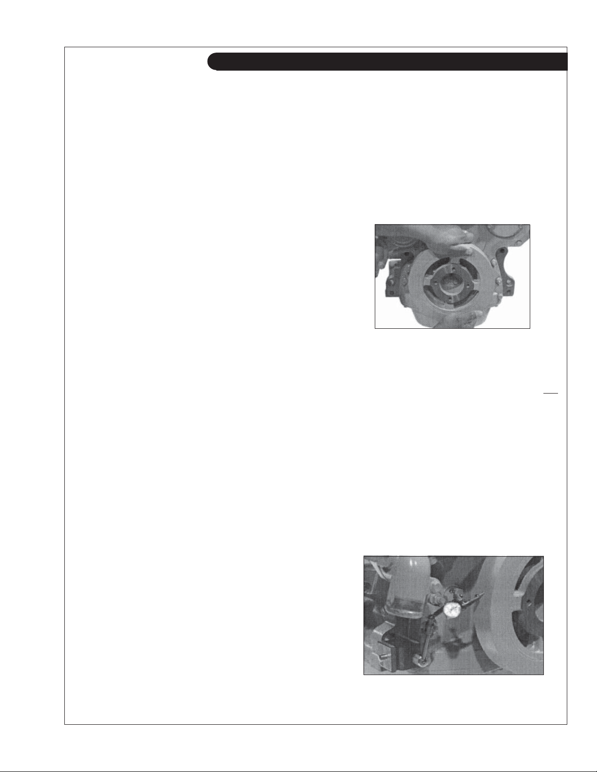
SP7. CRANKSHAFT VIBRATION DAMPER
(6 Cylinder Engines Only)
1. Remove belts.
2. Try to turn the vibration damper in both directions
while grasping it with both hands. If rotation can be
felt, the damper is defective and should be replaced.
Reproduced by permission of Deere & Company, c2004. Deere & Company. All rights
reserved. RG8018 Figure 12
NOTE: The vibration damper assembly should be
replaced every 4500 hours or 60 months, whichever
occurs fi rst, as the vibration damper assembly is not
repairable.
3. Place a dial indicator (Figure 13) so that the probe
contacts the damper’s outer diameter in order to
check the damper radial runout.
4. Make sure the engine is at operating temperature,
then rotate the crankshaft using the JD281A,
JDE81-4, or the JDE83 Flywheel Turning Tool.
5. If the runout reading exceeds the below
specifi cation, replace the vibration damper.
Vibration Damper Maximum
Radial Runout ..........................1.50 mm (0.060 in.)
Reproduced by permission of Deere & Company, c2004. Deere & Company. All rights
reserved. RG7508 Figure 13
OM2-2 06/10
17
Page 20
Servicing
SP8-10. FUEL FILTERS (Continued)
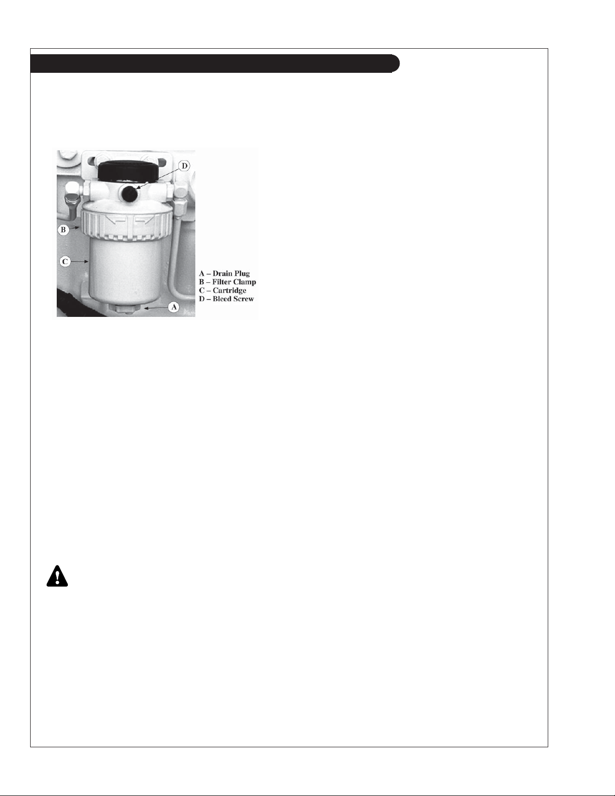
a. Turn off the fuel.
b. Open the fi lter drain plug (Figure 14-A) and drain
the fi lter.
Figure 14: Secondary Fuel fi lter
c. Remove the secondary fuel fi lter by turning the
fi lter clamp (Figure 14-B) counter clockwise until
the fi lter cartridge (Figure 14-C) slides out.
NOTE: Before installing a new fi lter cartridge make sure
the surfaces where the cartridge comes in contact with the
mounting plate are absolutely clean. Dirt can be washed
into the fuel injection system. This may result in severe
damage to the fuel injection pump or nozzles. Your
generator set may have two secondary fi lters, depend-
ing on the fuel supply system. Do not “prefi ll” the new
fuel fi lter as the fuel used may be contaminated and
damage the fuel system components.
d. Install new fi lter cartridge.
e. Turn on the fuel.
BLEEDING THE FUEL SYSTEM
CAUTION: Escaping diesel fuel under pressure
can penetrate the skin, causing serious personal
injury. Before disconnecting lines be sure to
relieve all pressure. Before applying pressure to
the system be sure all connections are tight and
the lines, pipes and hoses are not damaged. Fuel
escaping from a very small hole can be almost
invisible. Use a piece of cardboard or wood rather
than the hands to search for suspected leaks. If
injured by escaping fuel, see a doctor at once.
Serious infection or reaction can develop if proper
medical treatment is not administered immediately.
1. Whenever the fuel system has been opened for service,
(lines disconnected, fi lter changed, etc.) it will be
necessary to bleed air from the system.
a. To bleed the fuel system, loosen the bleed plug
(Figure 14-D) on the fuel fi lter.
Operate the primer pump lever on fuel transfer
pump (see component locations) until most of the
air bubbles are expelled and clear fuel escapes the
bleed plug. Tighten the bleed plug.
b. If the engine will not start, it may be necessary to
loosen the fuel supply pipe at the pump. Operate
primer lever of fuel supply pump until fuel fl ow
is free from air bubbles. Retighten fuel supply
line to 22 ft. lb. (30 N•m).
c. If engine still doesn't start, loosen fuel line
connection at injection nozzle. Always use a back
up wrench when loosening or tightening fuel lines
at nozzles and injection pump to avoid damage.
With throttle on full, crank the engine over with
the starter until fuel without air fl ows from the
loose fuel pipe connection. Repeat procedure for
remaining nozzles, if necessary, until engine
starts or until air has been removed from system.
Tighten the connections to 20 foot lb. (27 N•m).
d. For models M1066A2 and M1066A3 bleed the fuel
system using the electronic transfer pump. The
ignition should be on and allow 40 seconds for the
pump to complete the priming. If additional system
bleeding is needed, do it by loosening the fuel line
connections at the injection nozzles.
SP11. INJECTORS
1. Fuel injectors should be checked by a Lugger-Northern
Lights dealer or qualifi ed fuel injection shop every 500
hours.
2. Injector Removal:
You will need the following special tools:
JDE38A-Injection Nozzle Puller
JDE39-Nozzle Bore Cleaning Tool, JD258-Pilot Tool
a. Before removal, carefully remove all dirt from
the cylinder head around fuel injection nozzles.
Clean with compressed air to prevent dirt from
entering the cylinders or valve seats. Plug the
bore in the cylinder head after each fuel injection
nozzle has been removed. Cap fuel line openings
as soon as they are disconnected.
b. Immediately fi t protective caps over the nozzle
tips and the line connections to avoid handling
damage.
OM2-2 06/10
18
Page 21
Servicing
c. Do not bend the fuel delivery lines. When
loosening the fuel pressure lines, hold male union
of nozzle line stationary with a backup wrench.
d.
Loosen nuts to remove leak-off lines and T-fi ttings
and disconnect fuel injection line from nozzle.
NOTE: When all fuel injection nozzles have to be
removed, disconnect leak-off line assembly at fuel
tank, at injection pump, and at each nozzle T-fi tting.
Lift off complete leak-off line as an assembly.
e. Remove cap screw, clamp and spacer.
f. Pull injection nozzle out of cylinder head with
JDE38A Injection Nozzle Puller.
NOTE: Do not use screwdrivers, pry bars, or similar
tools for this as they might damage the injection nozzle.
3. Clean Injector Bore:
Always turn the tool clockwise through the bore
even when removing from bore, otherwise tool may
become dull.
a. Clean nozzle bore with JDE39 Nozzle Bore
Cleaning Tool. Blow debris from bore with
compressed air and plug the bore to prevent entry
of foreign material.
4. Clean injection nozzles:
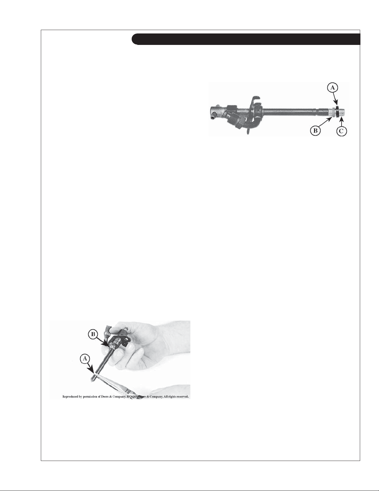
a. Remove carbon stop seal (Figure 15-A) and upper
sealing washer (Figure 15-B), using a needle-nose
pliers. Discard seals.
b. Clean exterior of nozzle by soaking in clean
solvent or diesel fuel. Clean tip with brass wire
brush.
This coating will become discolored during normal
operation, but this is not harmful. Do not use a motor
driven brush to clean up nozzle body.
Figure 16
5. Install seals on injection nozzle.
NOTE: Each time an injection nozzle is removed
from the cylinder head, replace carbon stop seal (B)
with a new one.
a. Position JD258 (ROS16477) Pilot Tool (Figure
16-C) over nozzle tip. If Pilot Tool (included in
cleaning kit) is not available, use a No. 16189
Nozzle Protector Cap found on every new or re placement nozzle.
b. Position a new carbon stop seal (Figure 16-B) on
pilot tool. Use a new seal washer (Figure 16-A) to
help slide the carbon seal into place until it seats
in its groove on nozzle body.
c. Continue to slide upper sealing washer onto
nozzle body until it seats against inlet fi tting.
6. Install injection nozzles:
NOTE: Before installing injection nozzles, make sure
nozzles are clean and free from oil or grease. Do not
grease or oil the nozzles.
Reprinted by permission of Deere & Company, 2004. All rights reserved. RG6300
Figure 15
NOTE: Do not scrape or disturb the tefl on
coating on the nozzle body above the carbon stop
seal groove.
a. Remove plug (if installed previously) from nozzle
bore in cylinder head and blow out bore with
compressed air.
b. Make sure that the sealing surface of the cylinder
head (on which the seal washer will be resting) is
smooth and free of damage or dirt. This could
prevent proper sealing. Dirt and roughness could
also cause distortion to nozzle when the attaching
screw is tightened, making the valve stick.
c. Install nozzle in cylinder head using a slight
twisting motion as nozzle is seated in bore.
d. Install spacer and cap screw. Do not tighten
capscrew at this stage.
OM2-2 06/10
19
Page 22
Servicing
Install injection nozzles (continued):
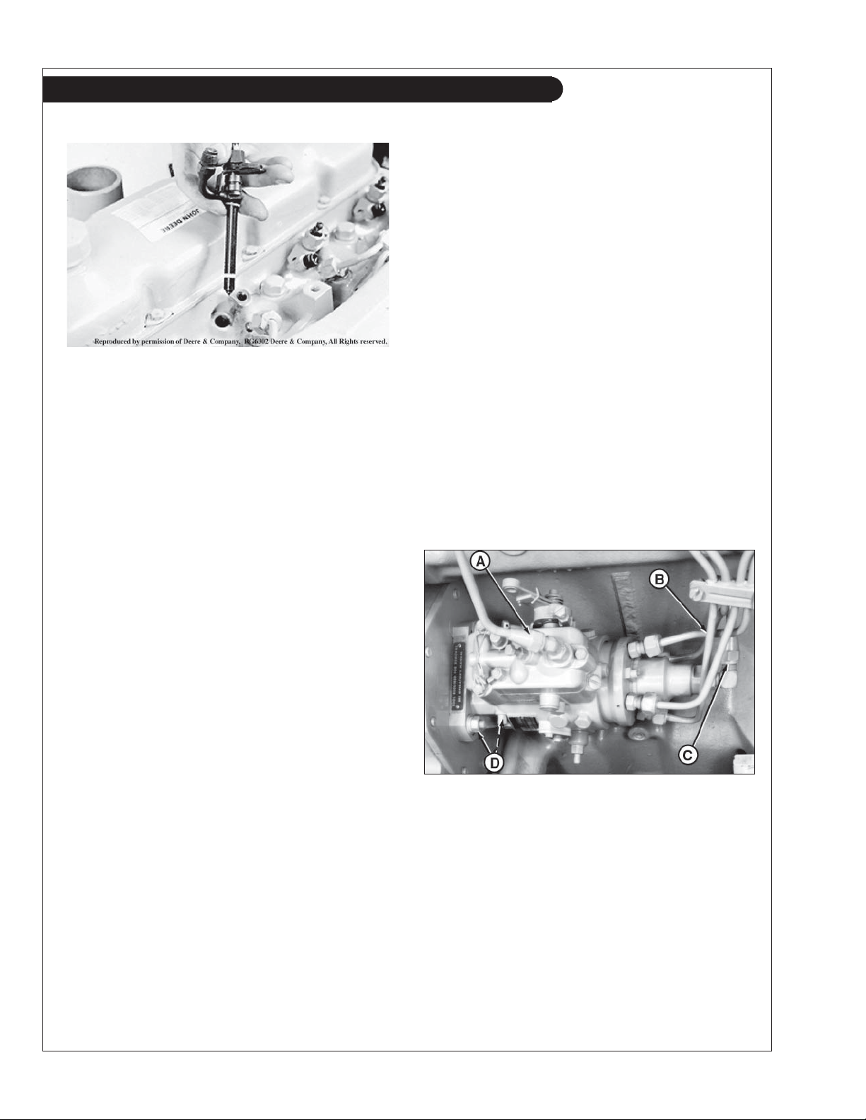
Figure 17: Shows relationship of parts required for
installation.
e. Connect fuel pressure line to nozzle. Leave
connection slightly loose until air is bled from
system.
f. Tighten nozzle hold-down cap screws to 27 foot
lb. (37 N• m).
g. Install leak-off assembly.
h. Bleed air from loose injection line connection.
Tighten connection using two wrenches.
DB4 AND DB2 INJECTION PUMPS – REMOVAL
All Stanadyne DB2 and DB4 injection pumps will
have a retained drive shaft (shaft stays in pump when
pump is removed from engine).
1. Clean the fuel injection pump, lines, and area around
the pump with cleaning solvent or a steam cleaner.
IMPORTANT: Never steam clean or pour cold water
on a fuel injection pump while the pump is running
or while it is warm. Doing so may cause seizure of
internal rotating pump parts.
2. Disconnect shutoff cable and speed control
linkage or cold start switch, if equipped. Disconnect
electrical connection to shutoff solenoid or throttle
positioning solenoid. Tag electrical wires for correct
reassembly.
IMPORTANT: Always use a backup wrench when
loosening or tightening fuel lines at injection pump
so that discharge fi ttings are not altered which will
prevent internal pump damage.
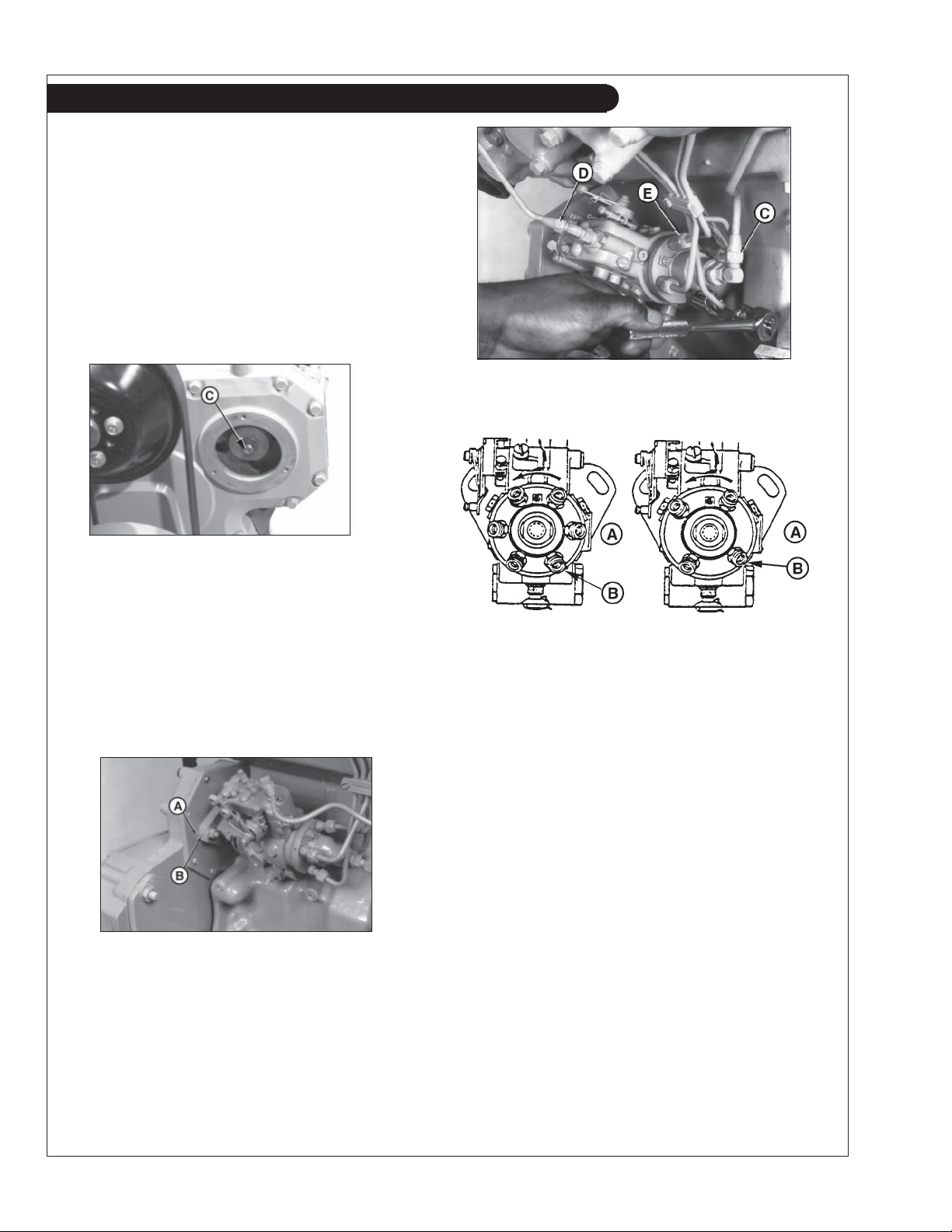
3. Disconnect fuel return line (Figure 18-A) and fuel
supply line (Figure 18-C).
SP12. INJECTION PUMP
1. Since operating conditions may vary considerably,
it is diffi cult to give a defi nite service interval. But,
as a rule, the pump settings, maximum speed, idle
speed and exhaust smoke should be checked by your
dealer after every 2000 hours of operation. Service
of the fuel injection pump should only be done if
checks indicate pump malfunction.
2. Black smoke can be an indication of pump
malfunctions. Before servicing pump, check the
other possible causes.
a. Check cleanliness of air fi lter.
b. Check valve clearances.
c. Clean and check injectors.
3.
Any repair which involves disassembly of the injection
pump must be carried out by specially-trained
mechanics with the proper tools and test devices.
NOTE: All warranties on the engine become null and
void if the injection pump seals are broken by
unauthorized persons.
Figure 18 Reproduced by permission of Deere & Company, c.2004. Deere & Company. All rights reserved.
RG5659
4. Disconnect all fuel delivery (pressure) lines (Figure
18-B) from injection pump using a suitable 17 mm
deep-well crowsfoot socket.
5. Remove injection pump drive gear cover. Remove
drive gear retaining nut and washer from end of
pump shaft. Be careful not to let washer fall
inside timing gear cover.
OM2-2 06/10
20
Page 23
Servicing
NOTE: The injection pump drive gear fi ts snugly onto
a tapered drive shaft and indexed by a hollow pin or
Woodruff key installed in drive shaft.
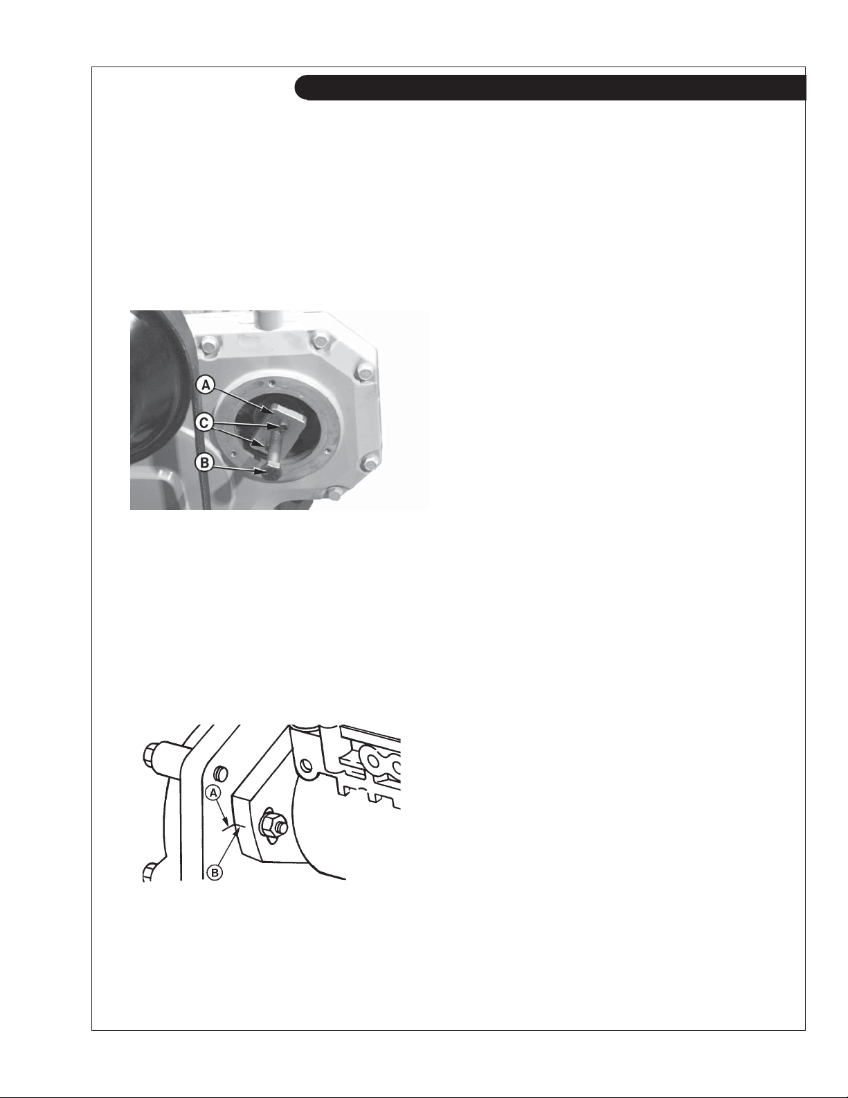
6. Attach JDG670A Drive Gear Puller (Figure 19-A) to
injection pump drive gear as shown.
NOTE: Replace 6mm Grade 12.9 cap screws (C) as
needed.
7. Evenly tighten the two 6mm, Grade 12.9 screws
(threaded in drive gear) and snugly tighten center
forcing screw (Figure 19-B) against end of pump shaft.
Figure 19 Reproduced by permission of Deere & Company, c.2004. Deere & Company. All rights reserved.
RG7757
8. Tighten center forcing screw until pump drive gear
is free from tapered shaft. Remove JDG670A puller
(Figure 19-A) and screws from drive gear.
9. Check to make sure that timing marks on back side
of front plate (Figure 20-A) and injection pump fl ange
(Figure 20-B) are present and properly aligned. This
assures that repaired or replacement pump can be
properly timed to engine when installed.
IMPORTANT: Injection pump mounting fl ange timing
mark (Figure 20-A ) and front plate timing mark
(Figure 20-B) presence and alignment MUST be
verifi ed before removing pumps from engine. DO
NOT reference internal timing marks (on pump cam
ring and governor weight retainer). If timing mark is
not clearly visible on front plate, make a visible
reference mark as accurately as possible in-line with
mark on pump fl ange
.
10. Remove three injection pump mounting stud nuts.
Remove injection pump from mounting studs.
11. Plug or cap all openings on injection pump and take
pump to dealer for service
DB4 & DB2 INJECTION PUMP – INSTALLATION
1. Lubricate a new square sealing ring with clean
engine oil. Install ring into groove on front face of
pump mounting fl ange. Slide injection pump onto
mounting studs while inserting pump shaft into drive
gear.
2. Check pump shaft and index pin for proper
alignment with pump drive gear key slot.
IMPORTANT: Shaft roll pin may be easily damaged
if improperly assembled. Pump drive gear should
not move when initially installing pump index pin into
drive gear key slot.
3. Install injection pump partially onto mounting studs
without engaging pump pilot hub into engine front
plate.
IMPORTANT: DO NOT tighten hex nuts more than
three full turns on mounting studs. Pump drive shaft
index pin may be damaged if pin is not properly
aligned with drive gear key slot and if the nuts are
tightened more than three turns.
Figure 20 Reproduced by permission of Deere & Company, c.2004. Deere & Company. All rights reserved.
RG6293
OM2-2 06/10
4. Install three fl at washers, lock washers, and hex nuts
onto pump mounting studs. Tighten nuts three turns
only so that pump will not fall off mounting studs.
NOTE: The pump drive gear should begin to move
forward (away from engine front plate) with the pump
when fl ange is approximately 1/8 in. (3.2 mm) away
from engine front plate.
21
Page 24
Servicing
5. Install pump mounting fl ange fl ush to engine front
plate with drive gear held fl ush against front side of
engine front plate.
IMPORTANT: Do not use tightening force of pump mount-
ing stud nuts to pull pump shaft into drive gear I.D.
6.
With the pump shaft index pin properly engaged in the
drive gear key slot, fi nger tighten mounting stud nuts.
7.
Push pump drive gear fi rmly onto shaft taper. Install
washer and retaining nut (Figure 21-C) onto end of shaft.
Tighten retaining nut to 90 lb-ft. (122 N•m) for DB2,
150 lb-ft. (203 N•m) for DB4.
Figure 21 Reproduced by permission of Deere & Company, c.2004. Deere & Company, All rights reserved.
RG7630
Figure 23 Reproduced by permission of Deere & Company, c.2004. Deere & Company, All rights reserved.
RG5664
IMPORTANT: Do not overtighten cap screws on pump
cover plate to avoid damage to O-ring.
8. Install access cover plate using a new gasket. Apply
LOCITE 242 (TY9370) to cap screw threads and
tighten to 1.7 lb-ft. (2 N•m).
9.
Align timing mark on the pump fl ange (Figure 22-B) with
timing mark on the cylinder block front plate (A).
Figure 22 Reproduced by permission of Deere & Company, c.2004. Deere & Company, All rights reserved.
RG6278
10. Tighten the three hex nuts securing the pump to the
front plate to 20 foot lbs. (27 N•m).
11. Connect injection pump pressure lines (Figure 23-E).
Beginning with outlet connection to #1 cylinder (Figure
24-B) and continue around the pump head in counter-
clockwise direction, attaching lines in same order as
engine fi ring (1-5-3-6-2-4 on 6-cylinder engines and
1-3-4-2 on 4-cylinder engines).
Figure 24 Reproduced by permission of Deere & Company, c.2004. Deere & Company, All rights reserved.
RG9089
12. Tighten fuel delivery (pressure) lines to 20 foot lbs.
(27 N•m), using a suitable 17 mm deep-well crowsfoot socket.
IMPORTANT: Always use a backup wrench when
loosening or tightening fuel delivery lines at fuel
injection pump, so that the pump discharge fi ttings
are not altered. This prevents possible internal pump
damage.
13. Connect fuel supply line (Figure 23-C) and fuel return
line (Figure 23-D).
14. Connect fuel shutoff cable and speed control linkage,
if equipped. Install and securely tighten electrical
connections to shutoff solenoid and throttle positioning solenoid, if equipped. Connect cold start switch,
if equipped.
15. Bleed air from fuel system as outlined on page 18.
Start engine and run for several minutes. Check the
entire system for leaks.
OM2-2 06/10
22
Page 25
Servicing
SP13. TURBOCHARGER
1. Check for air leaks every 100 hours. Air leakage
will lower engine output and may cause black
exhaust smoke and soot.
2. Listen along air line while engine is running.
A whistling or hissing sound indicates leakage.
3. Leakage on the pressure side, between turbo and
engine, can be found by applying soapy water to the
air line.
4. Tighten the hose clamps, replace hose or gaskets as
required.
5. Check to see that the lubrication and cooling lines
are tight and without leaks.
SP14. TURBO BOOST
1. This check measures the amount of air the turbo
is pushing into the engine. It should be done by an
authorized dealer every 500 hours.
2. On the inlet manifold there is a 1/8" NPT threaded
port. Remove the plug and install the boost gauge
hose. Refer to your engine specifi cations for correct
pressure.
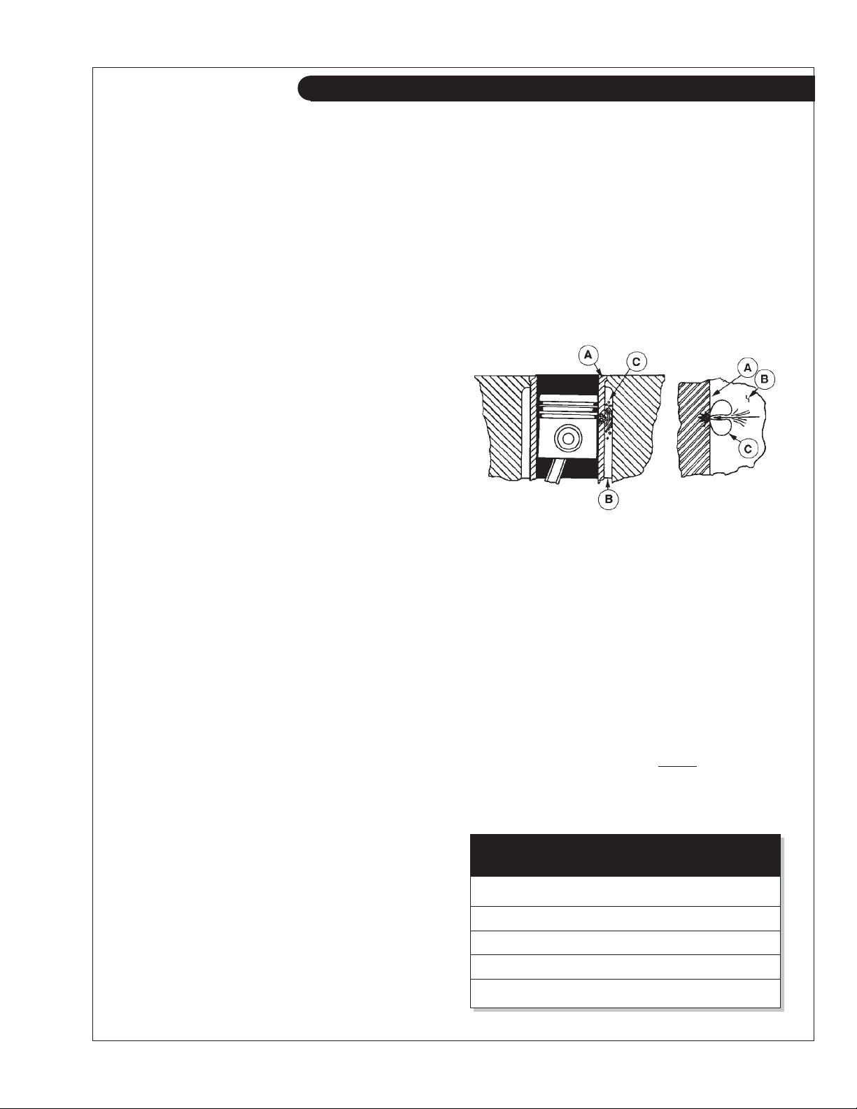
2. Vapor bubbles (Figure 25-C) are formed when the
piston's impact causes the liner walls to vibrate,
sending pressure waves into the coolant.
3. These tiny vapor bubbles collect on the surface
of metal parts. As the bubbles collapse (pop) a
microscopic piece of metal is eroded from the
metal part. Over a period of time, this pitting may
progress completely through the cylinder liner of a
wet-sleeve, heavy-duty diesel engine. This allows
coolant to enter the combustion chamber. Engine
failure or other serious damage will result.
COOLING REQUIREMENTS
1. To meet cooling system protection requirements, the
coolant solution must consist of:
a. Quality water
b. Ethylene glycol concentrate (EGC ) commonly
known as antifreeze.
c. Supplemental coolant additives (SCA's).
2. A coolant solution of ethylene glycol concentrate
(EGC-antifreeze), quality water and supplemental
coolant additives (SCA's) MUST be used YEAR
ROUND to protect against freezing, boil-over, liner
erosion or pitting and to provide a stable, noncorrosive environment for cooling system components.
3. Ethylene glycol coolant concentrate (antifreeze)
normally DOES NOT contain the SCA chemical
inhibitors needed to control liner pitting or erosion,
rust, scale, and acidity.
LINER EROSION (PITTING)
1. Cylinder liner walls (Figure 25-A) which are in contact
with engine coolant (Figure 25-B) can be eroded or
pitted unless the proper concentration and type of
SCA's are present in the coolant. Water pump
impellers are also susceptible to pitting.
A - Cylinder Liner Walls B - Engine Coolant C - Vapor Bubbles
Figure 25
4. Unprotected engines with low quality water as
coolant can have liner failure in as few as 500 hours.
WATER QUALITY
1. Distilled, deionized, soft water is preferred for use in
cooling systems. Bottled distilled water from a food
store or water supplier is recommended. Tap water
often has a high mineral content. Tap water should
NEVER be put in a cooling system unless fi rst tested
by a water quality laboratory. Do not use water
made by the reverse osmosis method unless it has
been PH neutralized.
2. Here are acceptable water quality specifi cations:
Parts Grains
Contaminates per Million per Gallon
Maximum Chlorides 40 2.5
Maximum Sulfates 100 5.9
Maximum Dissolved Solids 340 20.0
Maximum Total Hardness 170 10.0
OM2-2 06/10
23
PH Level 5.5 to 9.0
Page 26
Servicing
3. If chlorides, sulfates or total dissolved solids are
higher than the above given specifi cation, the water
must be distilled, demineralized, or deionized before
it is used in a cooling system.
4. If total hardness is higher than 170 ppm and all
other parameters are within the given specifi cations,
the water must be softened before it is used to make
coolant solution.
EGC: ETHYLENE GLYCOL CONCENTRATE
(ANTIFREEZE)
CAUTION: EGC (Antifreeze) is fl ammable.
Keep it away from any open fl ame. Avoid contact
with eyes. Avoid contact with skin. Do not take
internally. In case of contact, immediately wash
skin with soap and water. For eyes, fl ush with
large amounts of water for at least 15 minutes.
Call a physician. KEEP OUT OF REACH OF
CHILDREN. Follow all warnings
on the container.
1. Ethylene glycol coolant concentrate is commonly
mixed with water to produce an engine coolant with
a low freeze point and high boiling point.
2. A low silicate form of ethylene glycol coolant is
recommended for all diesel engines.
3. Use an ethylene glycol coolant concentrate
meeting ASTM D 4985P, SAEJ1941, General
Motors Performance Specifi cation GM1899M,
or formulated to GM6038M.
4. This product is concentrated and should be mixed
to the following specifi cation.
5. If additional coolant solution needs to be added
to the engine due to leaks or loss, the glycol
concentration should be checked with a
hydrometer to assure that the desired freeze point is
maintained.
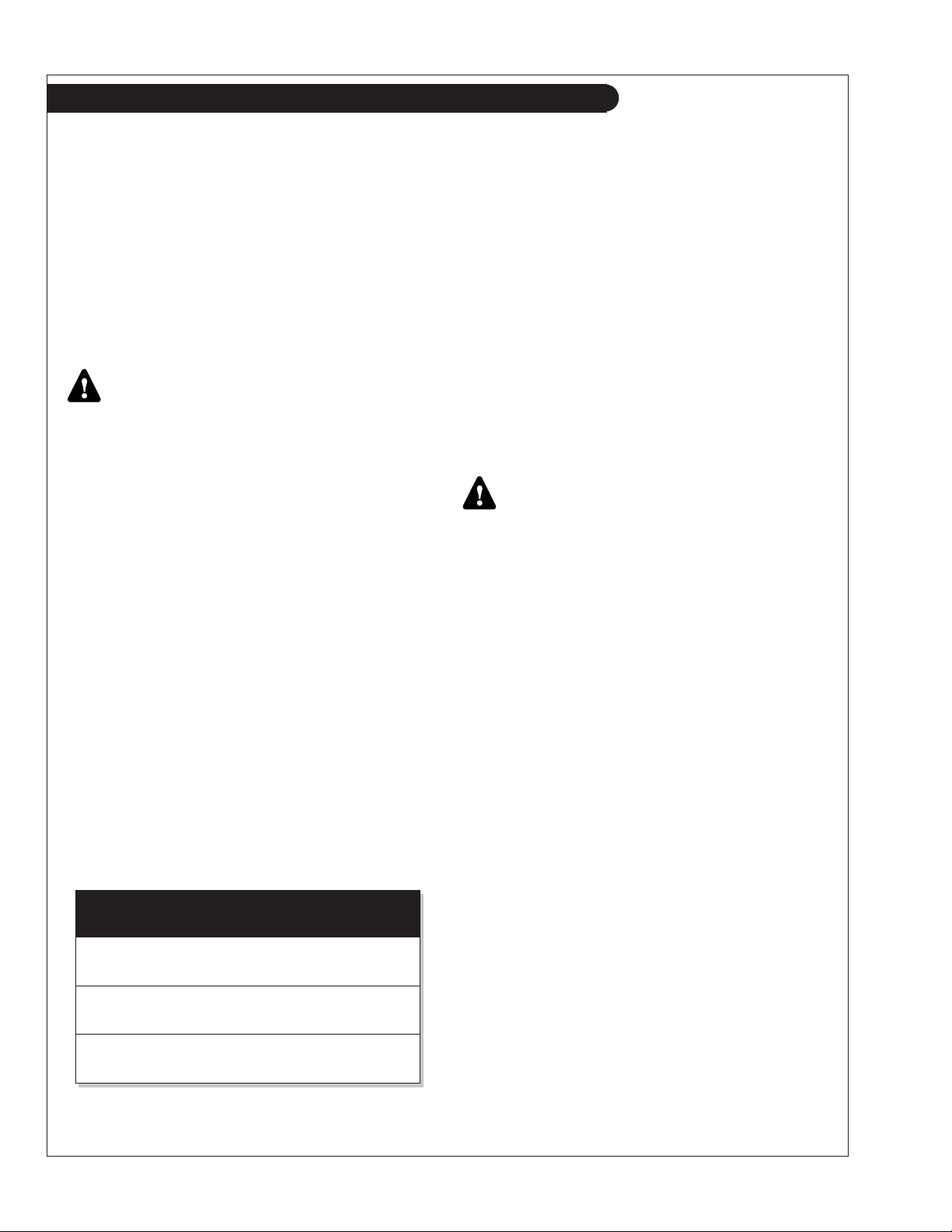
Distilled EGC % Freeze Boiling
Water % Antifreeze Point Point
Optimum 50% 50%
-34°F +226°F
Minimum 60% 40%
-12°F +222°F
Maximum 40% 60%
-62°F +232°F
-37°C +109°C
-24°C +106°C
-52°C +111°C
IMPORTANT
1. DO NOT use methyl alcohol or methoxy propanol
base EGC. These concentrates are not compatible
with chemicals used in supplemental coolant
additives. Damage can occur to rubber seals on
cylinder liners which are in contact with coolant.
2. DO NOT use an EGC containing sealer or stop-leak
additives.
3. DO NOT use EGC containing more than 0.1%
anhydrous metasilicate. This type of concentrate,
which is intended for use in aluminum engines, may
cause a gel-like deposit to form that reduces heat
transfer and coolant fl ow. Check container label or
consult with supplier.
SUPPLEMENTAL COOLANT ADDITIVE (SCA)
CAUTION: Supplemental coolant additive contains
alkali. Avoid contact with eyes. Avoid contact with
skin. Do not take internally. In case of contact
immediately wash skin with soap and water. For
eyes, fl ush with large amounts of water for at
least 15 minutes. Call a physician. KEEP OUT OF
REACH OF CHILDREN. Follow all warnings on the
container.
1. Important for heat exchanger cooled engines:
Additional SCA's should NOT be added to the
mixture of EGC/H20 on initial fi ll up of engines
with a coolant conditioner-fi lter. A high SCA
concentration will result and can cause
silicate-dropout. When this happens, a gel-type
deposit is created in the cooling system which
retards heat transfer and coolant fl ow.
2. If additional SCA's are needed, prepare a mixture
of 50% quality water and 50%EGC (antifreeze).
Add liquid SCA at a rate of 3%, by volume.
Example: 30 mL of SCA per liter of H2O/EGC
mixture (1.0 fl oz of SCA per qt of H2O/EGC).
Add the resulting mixture to the cooling system in
quart increments. Run the engine for 2 hours and
retest the coolant. Continue process until SCA
concentration meets recommended levels.
3. SCA is available from your Northern Lights dealer
in the following sizes.
Pint - Part Number...............20-00002
1/2 gallon - Part Number.....20-00003
4. DO NOT use any coolant system additives
containing soluble oil.
OM2-2 06/10
24
Page 27
Servicing
COOLANT TESTING
1. Coolant test kits are available to allow on-site
evaluation of the coolant condition.
2. The kits use small strips of paper which are dipped
into the coolant. The paper changes color and indicates
the SCA concentration. It also indicates the amount of
EGC (antifreeze).
3. Test kits are available through your Northern Lights or
Lugger Dealer.
4 Pack - Part Number.......................20-00005
50 Pack - Part Number.....................20-00010
SP15. CHECKING COOLANT LEVEL
CAUTION: The cooling water in the engine reaches
extremely high temperatures. You must use extreme
caution when working on hot engines to avoid
burns. Allow the engine to cool before working on
the cooling system. Open the fi ller cap carefully,
using protective clothing when the engine is warm.
1. Check the coolant level each day before starting the
engine.
2. Remove the pressure cap from the expansion tank and
check water level. In order to give the coolant
an opportunity to expand, the level should be about
1 3/4 in. (4-5 cm) below the fi ller cap sealing surface
when the engine is cold. When fi lling with coolant, the
venting cock on top of the turbocharger (for engines
fi tted with turbocharger) should be opened to ensure
that no air pockets form in the cooling system.
2. The pressure valve in the fi ller cap releases when the
pressure is approximately 7 PSI (0.5 bar). Use a cap
pressure tester to check cap if you suspect it is faulty.
4. The makeup coolant, added to compensate for loss or
leaks, must meet engine coolant requirements outlined
in previous section.
SP16. FLUSHING THE COOLING SYSTEM
CAUTION: The cooling water in the engine reaches
extremely high temperatures. You must use extreme
caution when working on hot engines to avoid burns.
Allow the engine to cool before working on the
cooling system. Open the fi ller cap carefully, using
protective clothing when the engine is warm.
1. Flush the cooling system and check for leaks and
blockage every 2000 hours. The engine must be
stopped and cold.
2. Close the seacock.
3. Remove the pressure cap from the expansion tank
with caution. If applicable, open the cooling system
air vent on top of turbocharger.
4. Open the drains on the exhaust manifold and engine
block. Drain the fresh water system (see Component
Locations, pages 4 - 6).
5. For vessels with keel cooling, the vessel must be out
of the water to allow draining of the keel cooler.
6. With drains open, pour clean water into the expansion
tank. When the water from drain is clear and free from
discoloration and sediment, close that drain. When all
drains are closed, fl ushing is complete.
7. Fill the fresh water system by pouring the
recommended coolant mixture as described in
previous sections.
8. Close cooling system air vent on turbocharger.
9. Open the seacock.
10. Start the engine. Check hoses and connections and
repair any leakage.
SP17. HEAT EXCHANGER CLEANING
1. Drain the cooling system.
2. Remove the cooling water pipes between the heat
exchanger and the water pump inlet.
3. Disconnect hose to seawater pump.
4. Unscrew the attaching bolts holding the heat
exchanger to the expansion tank.
5. Remove bolts holding heat exchanger cover.
6. Wash the core inside and out. If necessary, chemical
agents can be used. Also clean the accessible parts of
the heat exchanger housing.
7. Reassemble, using new gaskets and sealing rings.
SP19. ZINC ANODES
1. Zincs are installed in the cooling system to protect
your engine from electrolysis. Check them faithfully
every 250 hours. If you are in warm salt water or
where electrolysis is a known problem, check them
more often.
OM2-2 06/10
25
Page 28
Servicing
Heat exchanger cooled engine:
a. Drain the raw water from heat exchanger
(see Component Locations).
b. Remove zinc holders from back of the tank and
from front and port side of the heat exchanger
(see Component Locations).
Keel Cooled engines.
a. Drain expansion tank and remove zinc holder
from tank (see Component Locations).
2. Scrape or steel brush the zinc electrode clean. If
more than 50% of the electrode has eroded away,
replace it with a new one. The electrode screws out
of the holder.
3. Reinstall the zinc holders. Be sure the threads are
clean and have good metal to metal contact.
SP20. RAW WATER PUMP
Heat exchanged cooled engines only.
1. Change the sea water pump impeller as needed.
2. Remove the pump end cover. Remove impeller with
water pump pliers. Be sure you remove all pieces of
a failed impeller.
3. Clean the inside of the housing.
4. Press in the new impeller and place the sealing
washer in the outer end of the impeller center if this
has not already been done.
5. Replace the cover using a new gasket.
Note: Make sure there is always an extra impeller
and cover gasket in reserve and on-board.
DRIVEN EQUIPMENT
Gears and PTO's
1. Manufacturer's service recommendations vary. See
your Owner's Manual for service information. If you
do not have a manual, see your local dealer for the
equipment in question.
NOTE: Some PTO and marine gears have
rigid lubrication requirements. Follow service recom-
mendations closely.
Generator Ends
2. The maintenance and operation recommendations
for the generator end are in a separate Owner's
Manual. If you do not have one of these manuals,
contact your local Northern Lights dealer.
ELECTRICAL SYSTEM - GENERAL
1. Never switch battery switch off or break the circuit
between the alternator and batteries while the engine
is running. Regulator damage can result.
2. DO NOT reverse the polarity of battery cables when
installing the battery.
3. When welding on the unit, disconnect the regulator
and battery. Isolate the leads.
4. Disconnect battery cables when servicing the DC
alternator.
5. Never test with a screwdriver, etc., against any
terminal to see if it emits sparks.
6. A DC circuit breaker protects your control panel and
wiring harness.
OM2-2 06/10
26
Page 29
Servicing
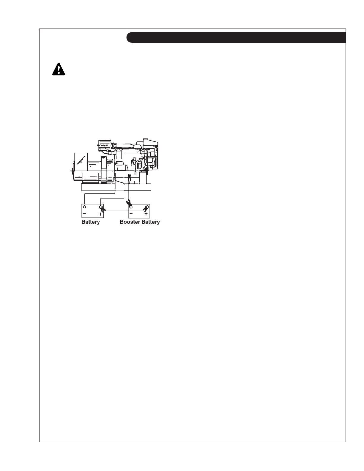
BOOSTER BATTERIES
CAUTION: Battery Gas Can Explode. Keep all
fl ames and sparks away from batteries.
1. Before changing or using booster batteries, check
battery electrolyte level. Add distilled water.
2. Booster and main batteries must have the same
voltage rating.
3. First, connect positive (+) terminal of booster
battery to positive (+) terminal of main battery.
Figure 26: Booster Battery Connections
4. Then, connect negative (-) terminal of booster battery
to ground on the engine block (see Figure 26).
5. Remove booster battery after starting engine.
6. Sealed batteries: see manufacturer charging and
booster instructions.
SP21-22. BATTERY CARE - LEAD/ACID TYPE
BATTERIES
1. Check electrolyte level every 50 hours or once per
month. Add distilled water to manufacturer's recommended level.
2. Batteries, cables and cable terminals should be
checked and cleaned every 100 hours. Clean corrosion with a water and baking soda solution. Flush
with clean water. Tighten terminals and grease them
to inhibit corrosion.
3. Check the battery condition with a hydrometer
every 500 hours.
1. Change the engine oil and replace the fi lter.
Service the air cleaner.
2. Drain, fl ush, and refi ll the cooling system.
3. Crank the engine a few times with a starter,
without starting the engine.
4. Remove and clean batteries.
5. All engine openings should be sealed with plastic
bags and tape.
6. Store in a dry protected place.
To Remove Generator Set from Long-Term Storage:
1. Take off all protective coverings and unseal all the
openings that were covered up.
2. Install batteries that are fully charged and connect
the terminals.
3. Install the fan and alternator belts if they had been
removed.
4. Fill the fuel tank.
5. Perform all pre-start checks.
6. Crank the engine for 20 seconds with the starter,
without letting the engine start. Wait 2 minutes
and crank the engine an additional 20 seconds to
make sure all bearing surfaces are well coated.
7. Start the engine and run at no load in a low idle for
several minutes. Make sure the engine is warmed
up and check gauges before going under load.
8. Check all gauges and check for leaks.
SP26. CRANKCASE VENT SYSTEM
1. For sea water aftercooled units the crankcase vent
system is a good option, and now standard equipment for M1064A, M1066A1, M1066A2, and
M1066A3 units as of July 2008.
Check the red fi lter service indicator button daily -
if it pops up the fi lter element needs to be changed.
After changing the element, unscrew the clear
plastic cover on the button and push the indicator
down to reset it, then replace the cover.
Note: This service should be performed with
the engine shut down. The vacuum in the fi lter
canister because of engine operation may make it
diffi cult to take apart.
Normally, the fi lter element should be changed
every 750 hours.
SP24. WINTERIZING, OUT-OF-SERVICE
If the generator set will not be used for more than 6
months the following preparations should be taken for
long term storage.
OM2-2 06/10
SP30. AFTERCOOLER
1. The aftercooler should be removed and inspected
for deposits and the air side cleaned every 2000
hours.
27
Page 30
Troubleshooting
If you cannot correct problems with these procedures, see your Lugger or Northern Lights dealer.
DC ELECTRICAL SYSTEM
Battery Will Not Charge
Loose or corroded connections:
• Clean and tighten battery connections.
Sulfated or worn out batteries:
• Check specifi c gravity of each battery cell.
• Check electrolyte level of each battery cell.
Loose or defective alternator belt:
• Adjust belt tension.
• Replace belt.
Undercharged Electrical System
Excessive electrical load from added accessories:
• Take off accessories or install higher output
alternator.
Engine idling excessively.
• Increase the engine RPM when there is a
heavy electrical load.
Poor electrical connections on battery, ground strap,
starter, or alternator.
• Inspect connections and clean if necessary.
Defective battery.
• Test battery.
Battery charging rate too high.
• Test charging system.
Starter Inoperative
PTO engaged.
• Disengage PTO.
Check DC circuit breaker:
• If the breaker is tripped, reset it.
Faulty start circuit relay.
• See dealer.
Blown main system fuse.
• Replace fuse.
Loose or corroded connections:
• Clean and tighten loose battery and harness
plug connection.
Low battery output:
• Check specifi c gravity of each battery cell.
• Check electrolyte level of each battery cell.
Defective electrical system ground wire:
• Repair or replace.
Starter Cranks Slowly
Low battery output:
• Battery is too small.
• Battery cables are too small.
Check specifi c gravity of each battery cell:
• Replace battery if necessary.
Check electrolyte level of each battery cell:
• If low, fi ll cells with distilled water.
Crankcase oil too heavy:
• Fill with oil of appropriate viscosity.
Loose or corroded connections:
• Clean and tighten loose connections.
Starter and Hour Meter Function but rest of
Electrical System Does Not Function
Blown fuse on magnetic switch.
• Replace fuse.
Entire Electrical System Does Not Function
Check DC circuit breaker:
• If breaker is tripped, reset it.
Faulty connection:
• Clean and tighten battery and harness plug
connections.
Sulfated or worn out batteries:
• Check specifi c gravity and electrolyte level of
each battery cell.
ENGINE
Engine Hard to Start or Will Not Start
Engine starting under load.
• Disengage PTO if applicable.
Improper starting procedure:
• See starting section of this manual. Take
special note of Bypass Switch operation.
No fuel:
• Check level of fuel in fuel tank.
Low battery output:
• Check electrolyte level and condition.
Excessive resistance in starting circuit:
• Clean and tighten all battery connections.
Crankcase oil too heavy:
• Use oil of proper viscosity.
Improper type of fuel:
• Consult fuel supplier and use proper type of
fuel for operating condition.
Water, dirt or air in fuel system:
• Drain, fl ush, fi ll and bleed system.
Clogged primary fuel fi lter element:
• Clean or replace fi lter element.
Clogged secondary fuel fi lter element:
• Replace fi lter element.
Dirty or faulty injection nozzles:
• Have your dealer check injection nozzles.
Electronic Fuel System problem (if equipped):
• See your dealer.
Injection pump not getting fuel or air in fuel system.
• Check fuel fl ow at supply pump or bleed fuel
system.
OM2-2 06/10
28
Page 31
Troubleshooting
If you cannot correct problems with these procedures, see your Lugger or Northern Lights dealer.
Engine Runs Irregularly or Stalls
Frequently
Below normal engine temperature:
• Remove and check thermostat.
Clogged primary fuel fi lter element:
• Clean or replace fi lter element.
Clogged secondary fuel fi lter element:
• Replace secondary fi lter element.
Water or dirt in the fuel system:
• Drain, fl ush, fi ll and bleed system.
Dirty or faulty injection nozzles:
• Have your dealer check injection nozzles.
Air in fuel system:
• Inspect clamps and hoses on suction side of
fuel pump for air leak, bleed fuel system.
Improper type of fuel:
• Consult fuel supplier and use proper type of
fuel for operating condition.
Lack of Engine Power
Intake air restriction:
• Service air cleaner.
• Service aftercooler.
Clogged primary fuel fi lter element:
• Clean or replace fi lter element.
Clogged secondary fuel fi lter element:
• Replace fi lter element.
Improper type of fuel:
• Consult fuel supplier and use proper type of
fuel for operating conditions.
Overheated engine:
• See “Engine Overheats” in next category.
Below normal engine temperature:
• Remove and check thermostat.
Injection pump out of time.
• See your dealer.
Electronic fuel system problem.
• See your dealer.
Turbocharger not functioning (if equipped).
• See your dealer.
Leaking exhaust manifold gasket.
• See your dealer.
Defective aneroid control line.
• See your dealer.
Restricted fuel hose.
• Clean or replace fuel hose.
Low fast idle speed.
• See your dealer.
Improper valve clearance:
• Reset valves. Best done by dealer.
Dirty or faulty injection nozzles:
• Replace injectors. Best done by dealer.
• See your local dealer.
Engine Overheats
Engine overloaded.
• Reduce the load.
Low coolant level:
• Fill tank or radiator to proper level.
• Check hoses for loose connections and leaks.
Keel cooling tubes have been painted (marine):
• Remove paint from tubes.
Stretched belt or defective belt tensioner.
• Check automatic belt tensioner and check belts
for stretching. Replace as required.
Low engine oil level.
• Check oil level, add oil as needed.
Incorrect grade of fuel.
• Use correct grade of fuel.
Cooling system needs fl ushing:
• Flush cooling system.
Defective thermostat:
• Remove and check thermostat.
Defective temperature gauge:
• Check water temperature with thermometer
and replace gauge if necessary.
Water pump impeller worn/broken:
• Check impeller and replace if necessary.
Engine Knocks
Low oil level:
• Add oil to engine crankcase.
Injection pump out of time:
• Call your dealer.
Below normal engine temperature:
• Check your thermostats.
• Check water temperature to see if temperature
gauge is working properly.
Engine overheating:
• See “Engine Overheating” section.
OM2-2 06/10
29
Page 32
Troubleshooting
If you cannot correct problems with these procedures, see your Lugger or Northern Lights dealer.
High Fuel Consumption
Engine overloaded.
• Reduce load.
Air in fuel system:
• Bleed fuel system.
Improper type of fuel:
• Use correct fuel for temperature.
Clogged or dirty air cleaner:
• Service air cleaner.
Improper valve clearance:
• See your dealer.
Injection nozzles dirty:
• See your dealer.
Injection pump out of time:
• See your dealer.
Electronic fuel system problem.
• See your dealer.
Engine not at proper temperature:
• Check your thermostats.
• Check water temperature with thermometer
and replace gauge if necessary.
Below Normal Engine Temperature
Thermostats not working properly:
• Check thermostats.
Temperature gauge not working properly:
• Check water temperature with thermometer.
Low Oil Pressure
Low oil level:
• Fill crankcase to proper level.
Improper type of oil:
• Drain and fi ll crankcase with correct oil.
Partially plugged oil fi lter:
• Replace fi lter.
High Oil Consumption
Break-in period:
• Oil consumption decreases after break in.
Crankcase oil too light:
• Use proper viscosity oil.
Oil leaks:
• Check for leaks in lines around gaskets and
drain plug.
Engine Emits Black or Gray Exhaust Smoke
Clogged or dirty air cleaner:
• Service air cleaner.
Clogged aftercooler:
• Service aftercooler.
Defective muffl er (back pressure too high):
• Have dealer check back pressure.
Improper fuel:
• Use correct fuel for temperature.
Engine overloaded.
• Reduce load.
Electronic fuel system problem.
• See your dealer.
Turbocharger not functioning.
• See your dealer.
Injection nozzles dirty:
• See your dealer.
Engine out of time:
• See your dealer.
Engine Emits White Smoke
Improper fuel:
• Use correct fuel for temperature.
Cold engine:
• Warm up engine to normal operating
temperature.
Defective thermostat:
• Remove and check thermostat.
Engine out of time:
• See your dealer.
Defective injection nozzles.
• See your dealer.
OM2-2 06/10
30
Page 33
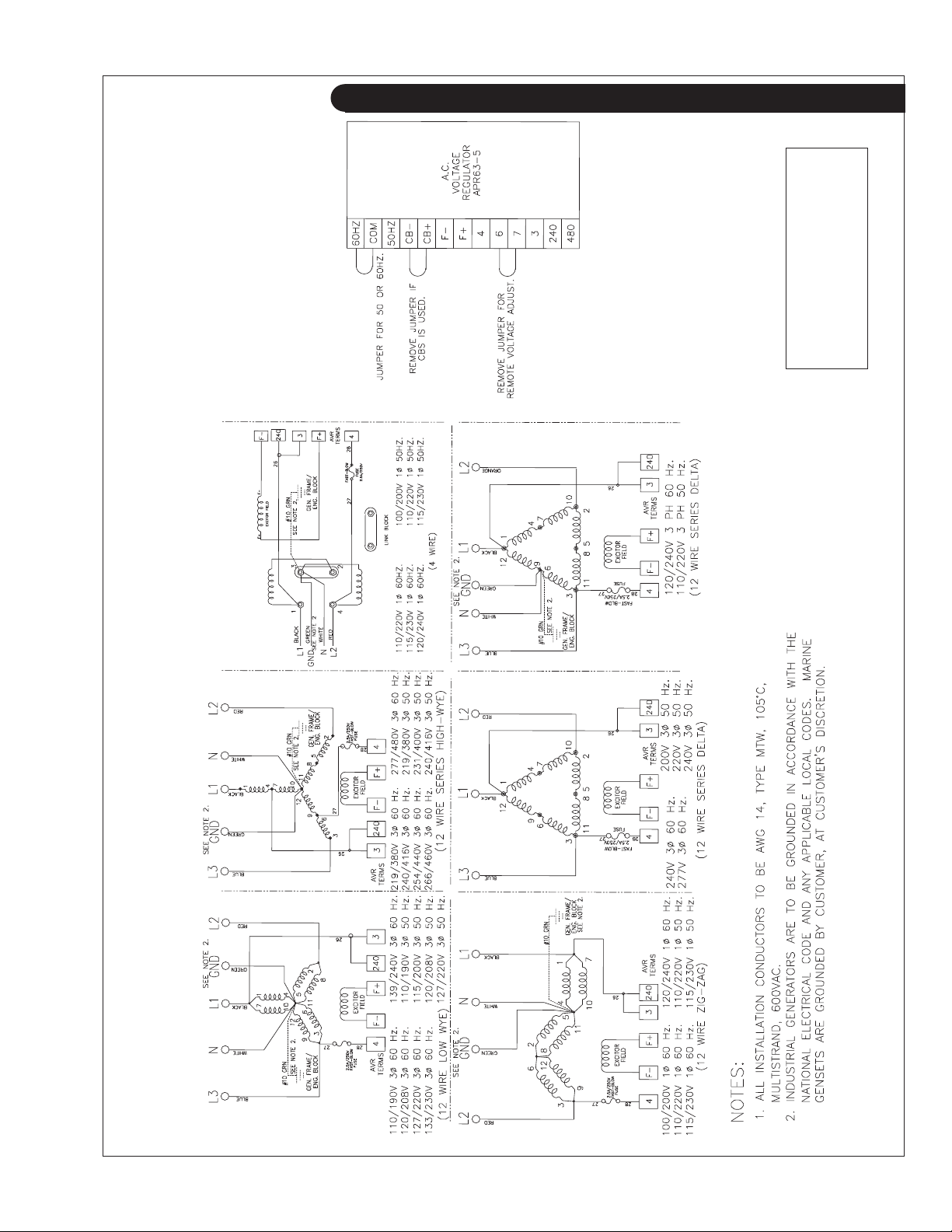
AC Wiring Diagram
Drawing B-5689D
A.C. Wiring - All voltages
with an APR63-5 (Non-PMG)
OM2-2 06/10
31
Page 34
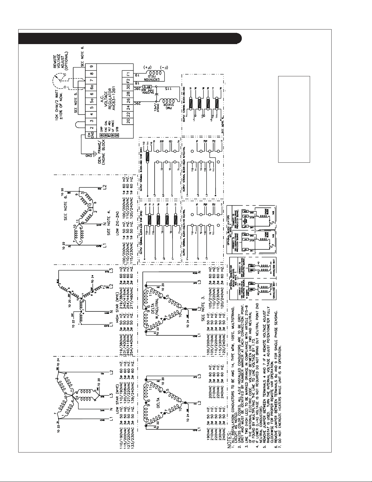
A.C. Wiring Diagram
Drawing B-7429G
A.C. Wiring - All voltages
with an AVC63-12B1 (PMG)
OM2-2 06/10
32
Page 35
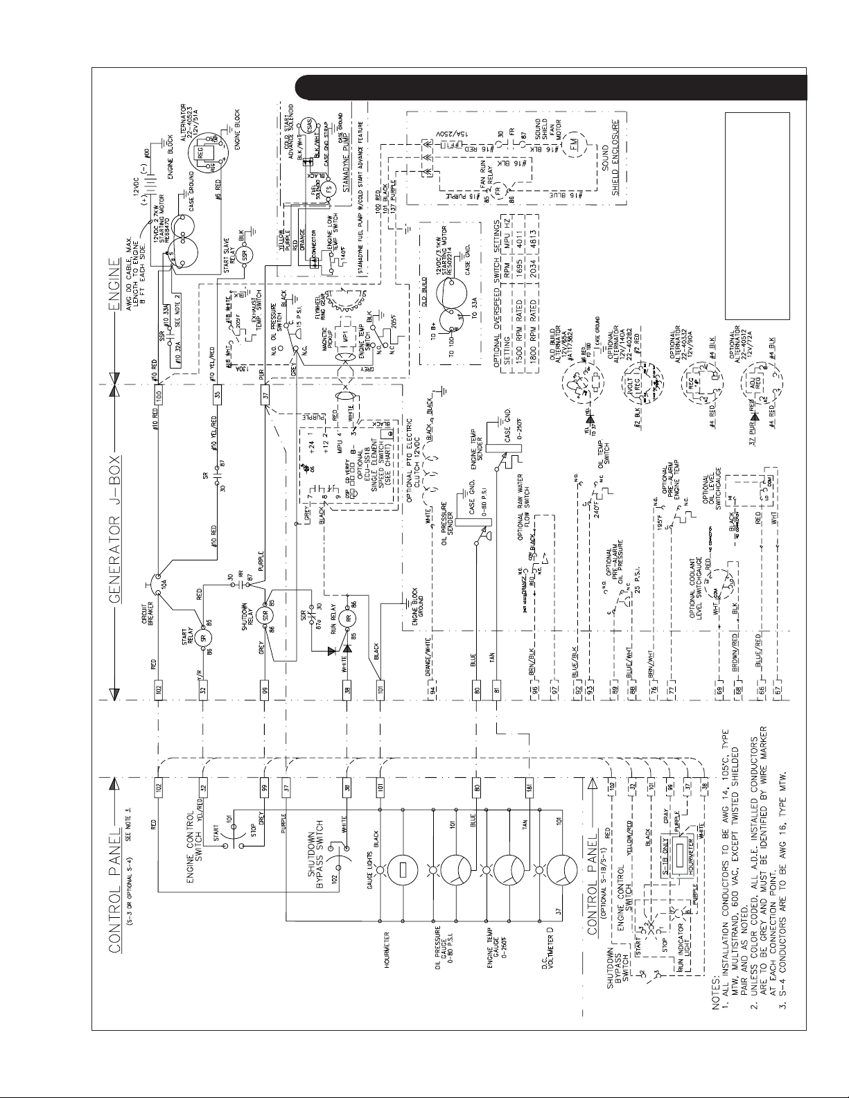
D.C. Wiring Diagram
D.C. Wiring - 12 Volt Standard
Ground for M1064D and M1064T1
Drawing C-5453J
OM2-2 06/10
33
Page 36
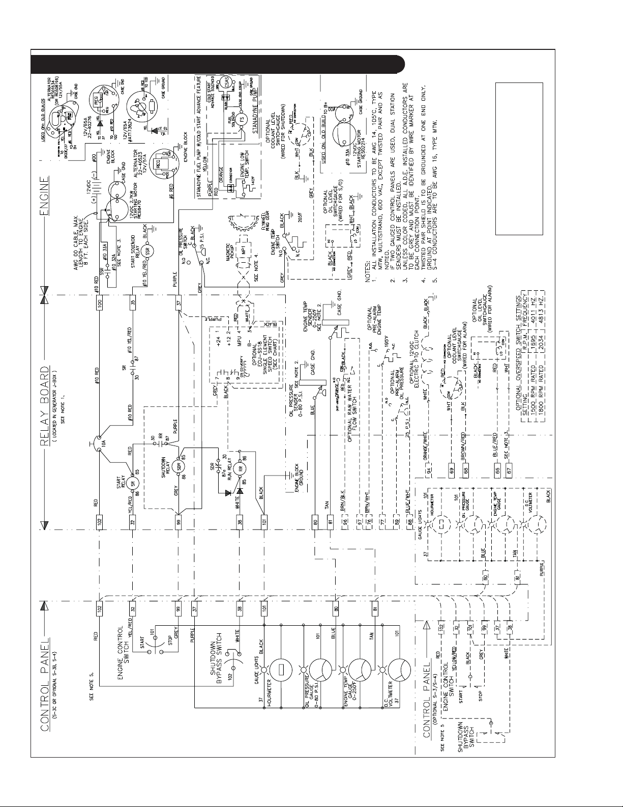
D.C. Wiring Diagram
Drawing C-5548J
Ground for M40C2 and M55C2
D.C. Wiring - 12 Volt Standard
OM2-2 06/10
34
Page 37
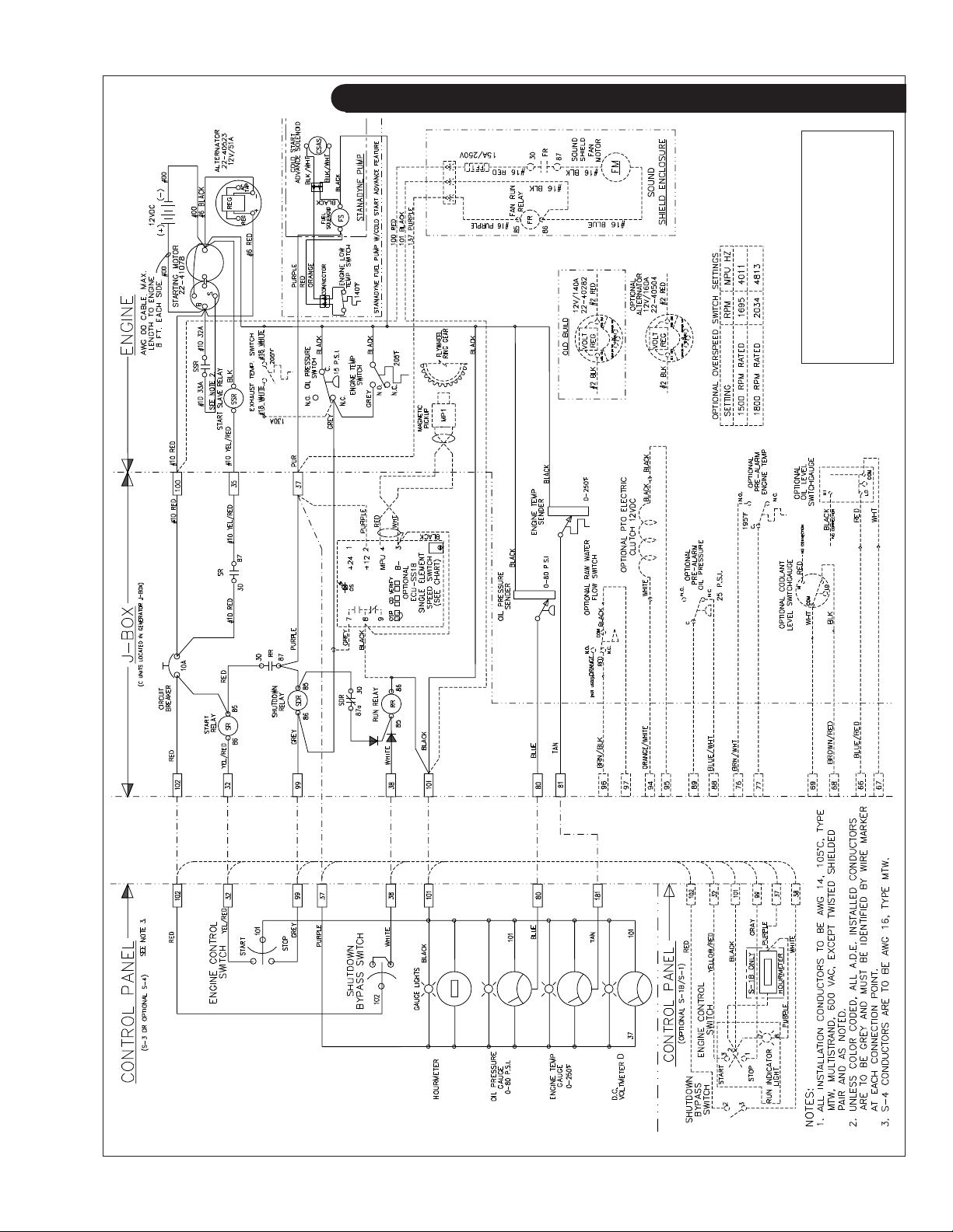
D.C. Wiring Diagram
M40C2, and M55C2
D.C. Wiring - 12 Volt Isolated
Ground for M1064D, M1064T1,
Drawing C-6062A
OM2-2 06/10
35
Page 38
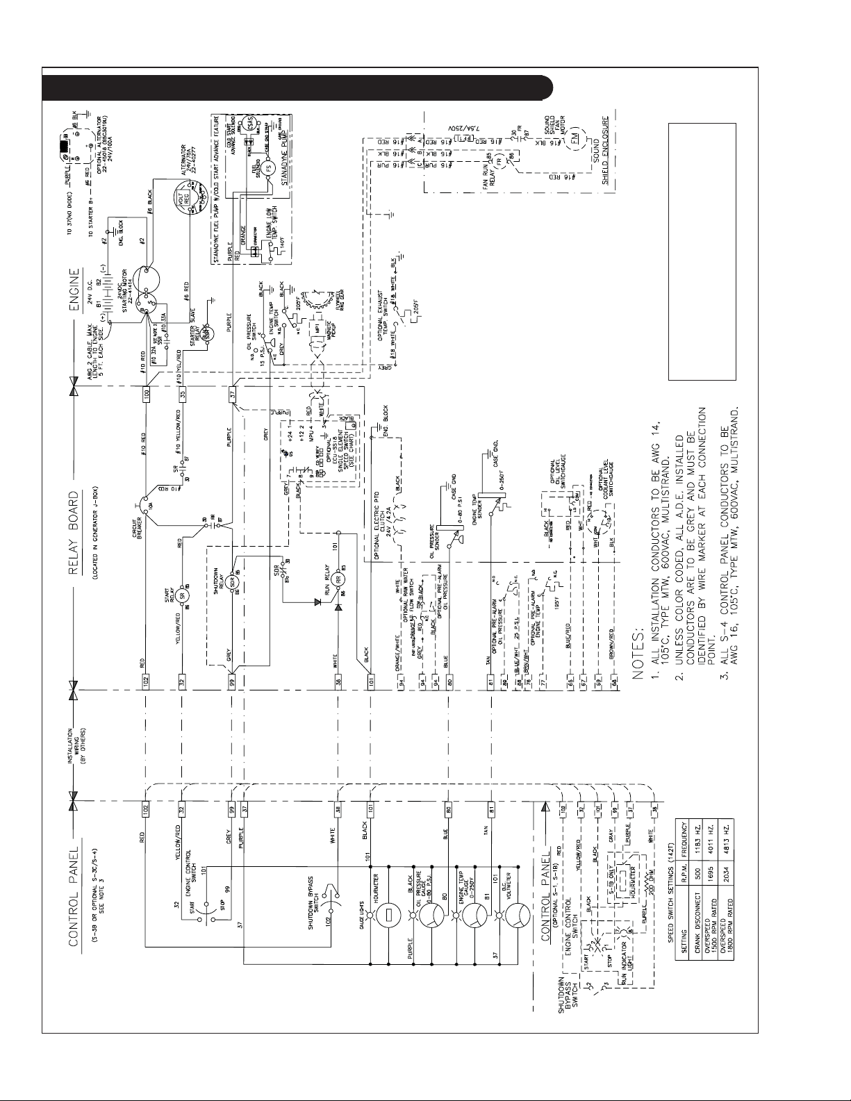
D.C. Wiring Diagram
Drawing C-5545C
M1064D and M1064T1
D.C. Wiring - 24 Volt Standard Ground for
OM2-2 06/10
36
Page 39
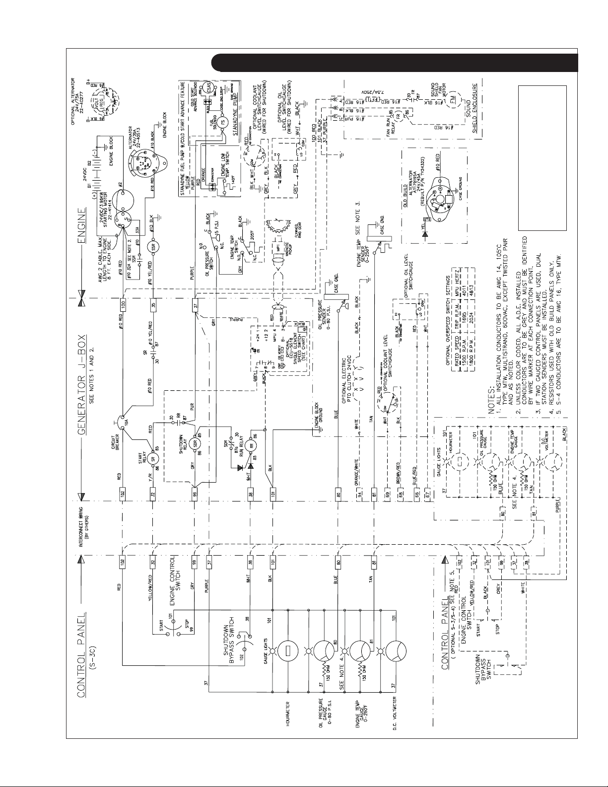
D.C. Wiring Diagram
D.C. Wiring - 24 Volt Standard
Drawing C-5562B
Ground for M40C2 and M55C2
OM2-2 06/10
37
Page 40
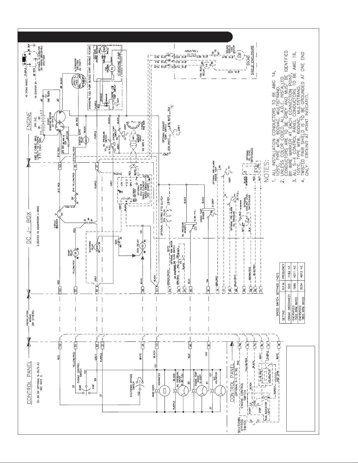
D.C. Wiring Diagram
OM2-2 06/10
38
Drawing C-5759C
D.C. Wiring - 24 Volt Isolated
Ground for M1064D and M1064T1
Page 41
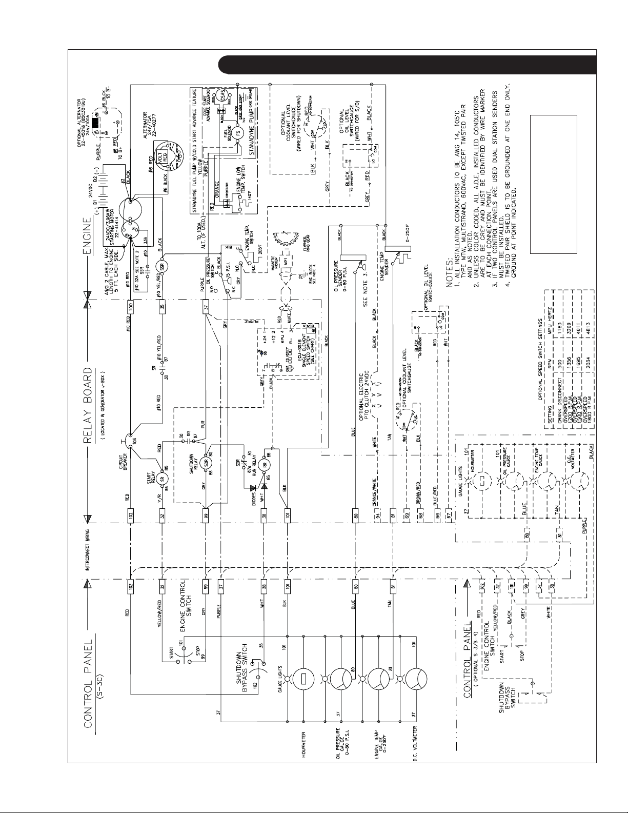
D.C. Wiring Diagram
Ground for M40C2, & M55C2
D.C. Wiring - 24 Volt Isolated
Drawing C-5623
OM2-2 06/10
39
Page 42
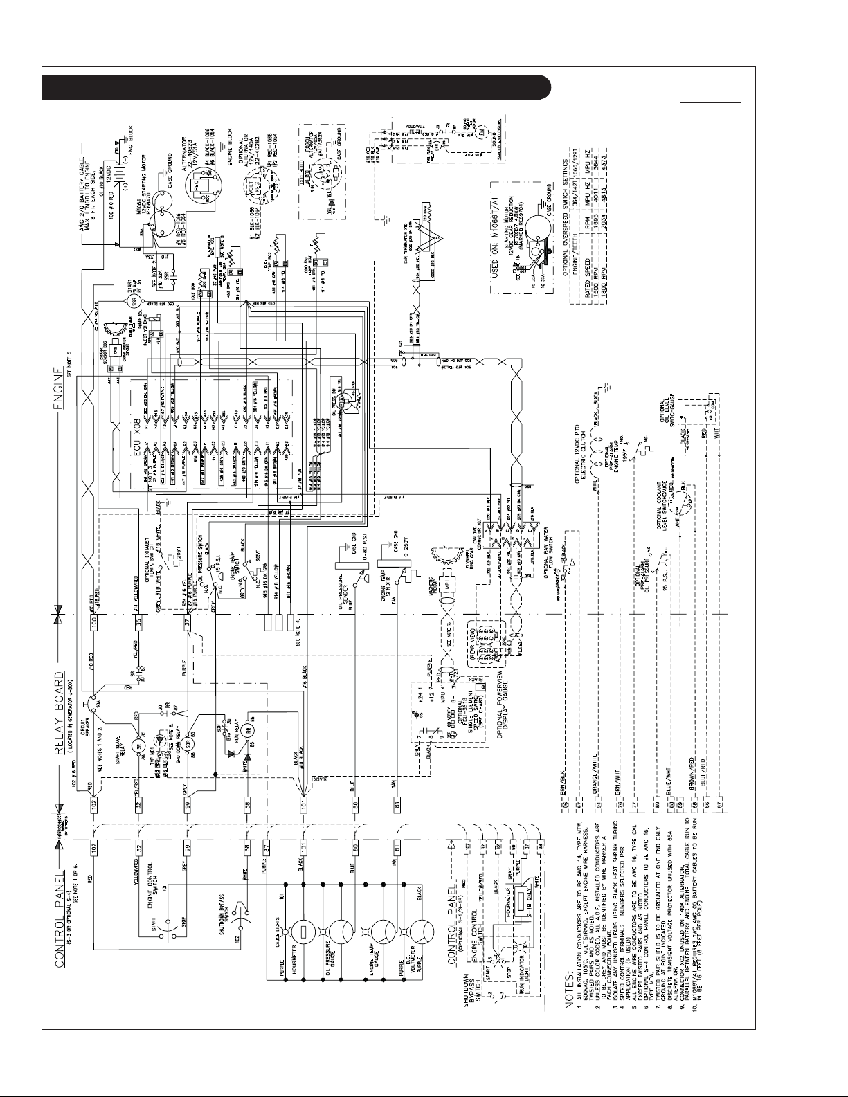
D.C. Wiring Diagram
Drawing C-5823C
D.C. Wiring - 12 Volt Standard Ground for
M1064T2, M1064A, M1066T, and M1066A1
OM2-2 06/10
40
Page 43
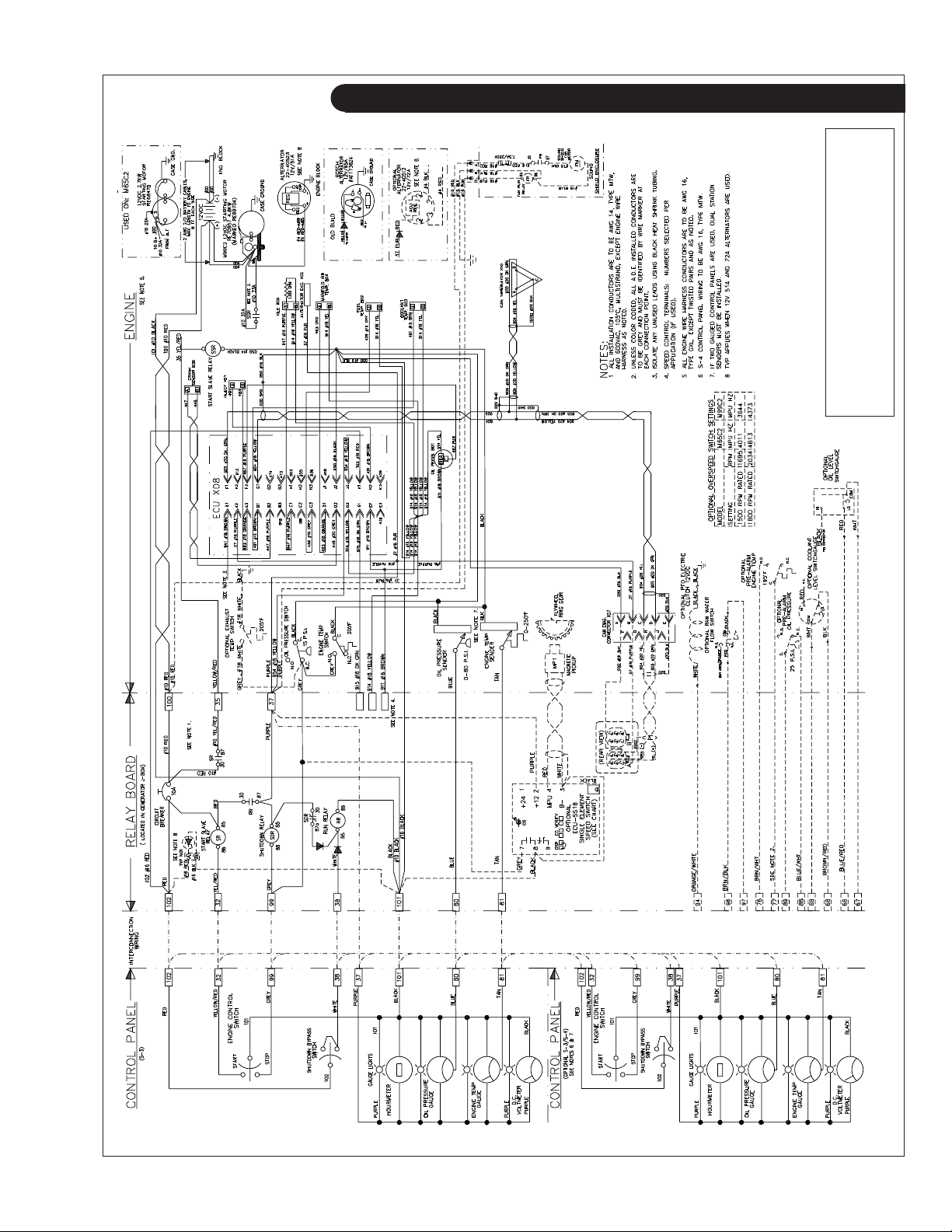
D.C. Wiring Diagram
D.C. Wiring - 12 Volt Standard Ground for
Drawing C-5808E
M65C2 and M99C2
OM2-2 06/10
41
Page 44
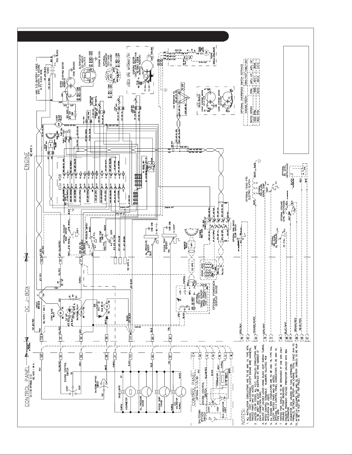
D.C. Wiring Diagram
Drawing C-6594
D.C. Wiring - 12 Volt Isolated Ground for
M10642, M1064A, M1066T, and M1066A1
OM2-2 06/10
42
Page 45
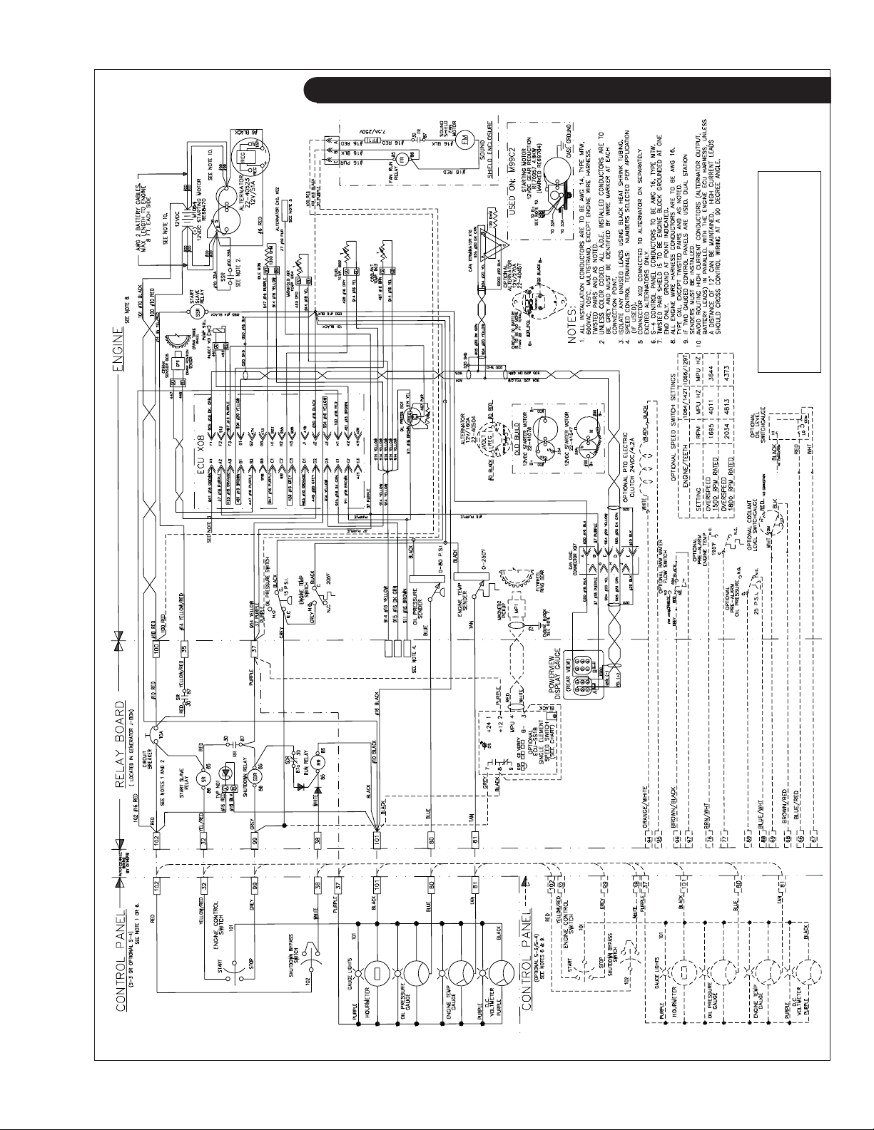
D.C. Wiring Diagram
D.C. Wiring - 12 Volt Isolated
Drawing C-6335A
Ground for M65C2 and M99C2
OM2-2 06/10
43
Page 46
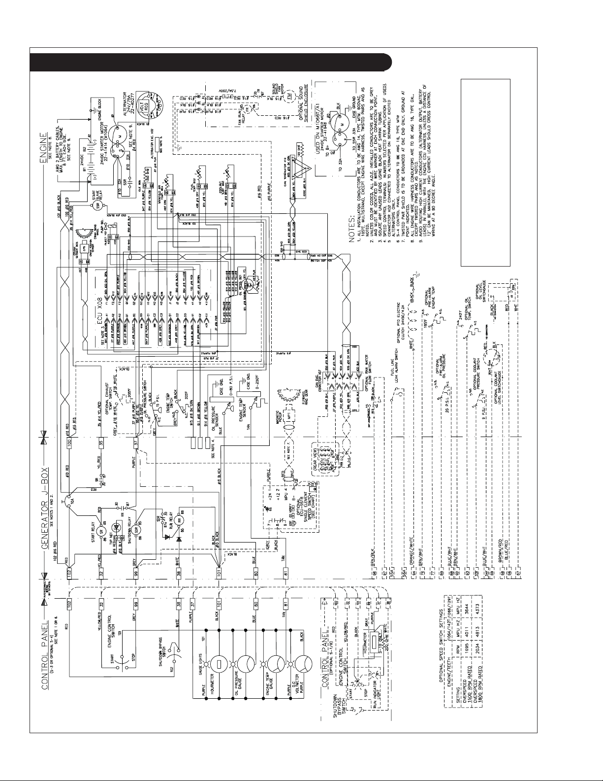
D.C. Wiring Diagram
Drawing C-5910E
D.C. Wiring - 24 Volt Standard Ground for
M1064T2, M1064A, M1066T, and M1066A1
OM2-2 06/10
44
Page 47
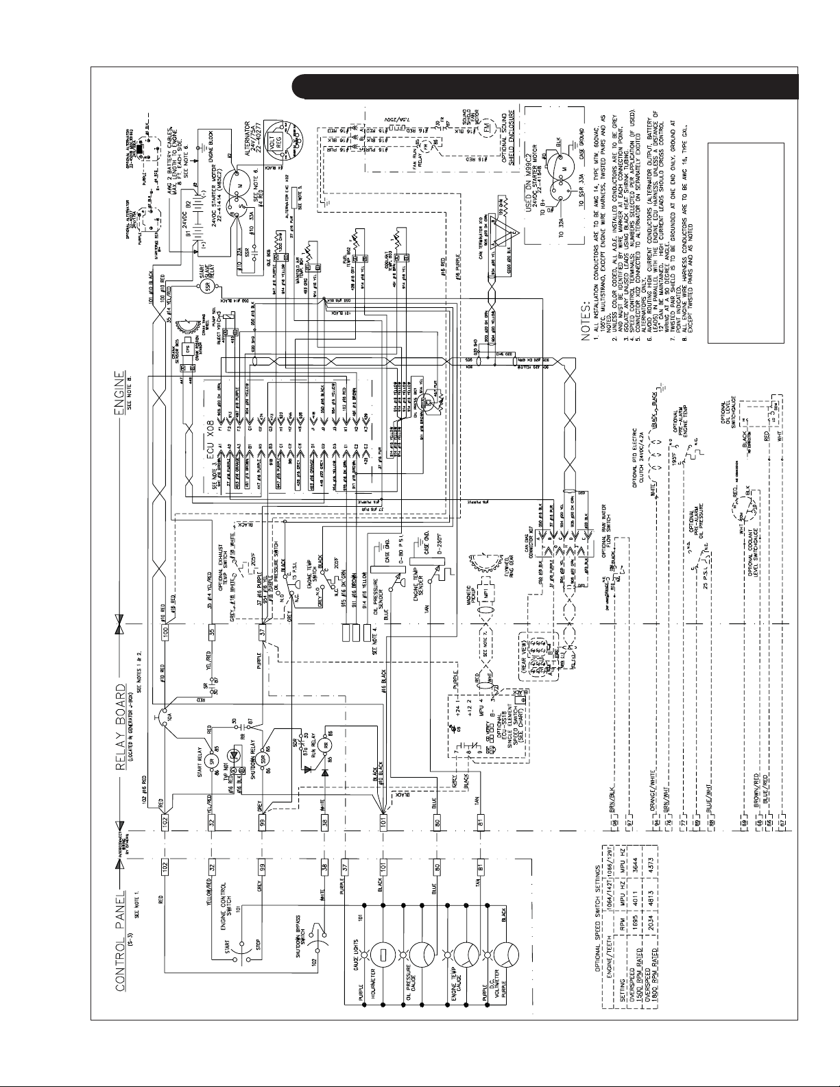
D.C. Wiring Diagram
D.C. Wiring - 24 Volt Standard
Drawing C-5794C
Ground for M65C2 and M99C2
OM2-2 06/10
45
Page 48
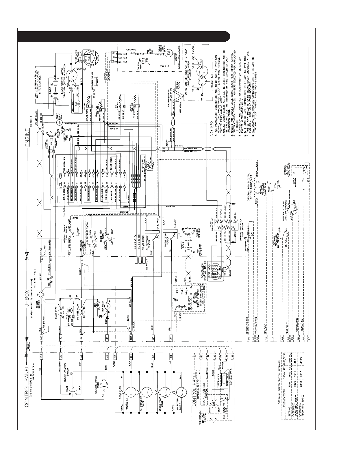
D.C. Wiring Diagram
Drawing C-5809F
M65C2, and M99C2
M1064T2, M1064A, M1066T, M1066A1,
D.C. Wiring - 24 Volt Isolated Ground for
OM2-2 06/10
46
Page 49
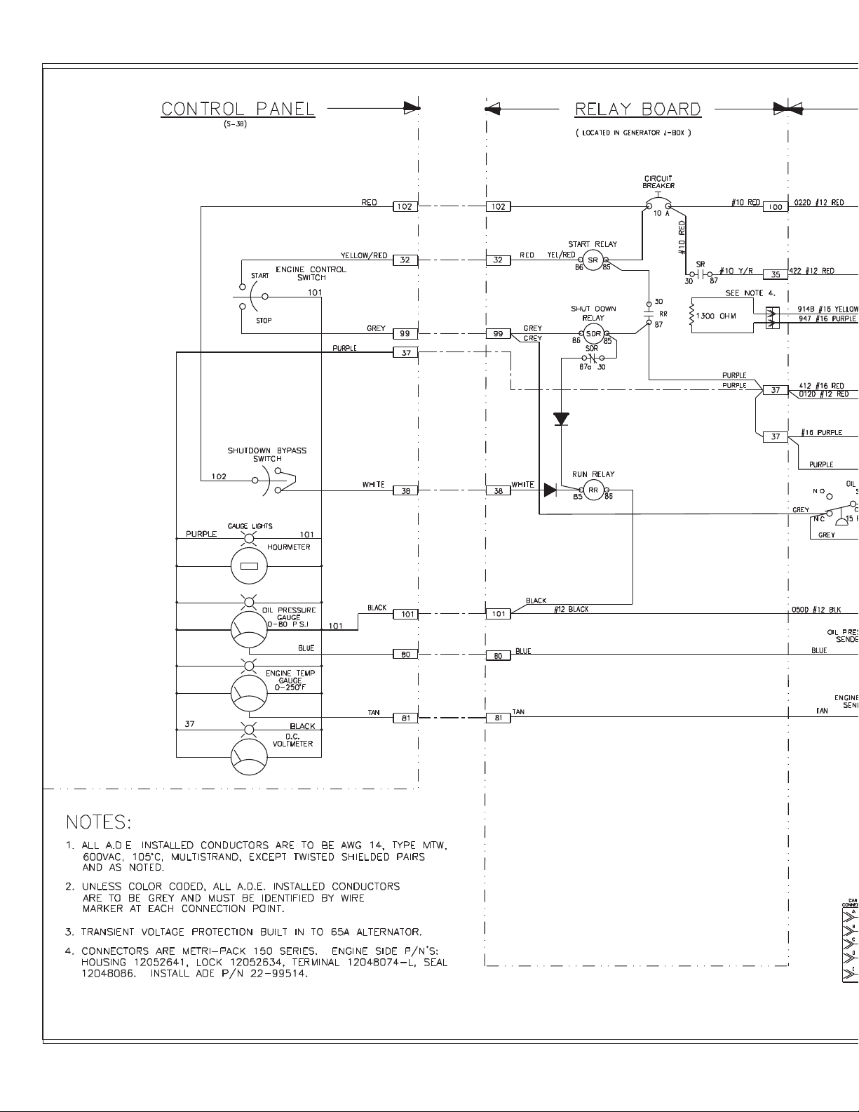
OM2-2 01/10
47
Page 50
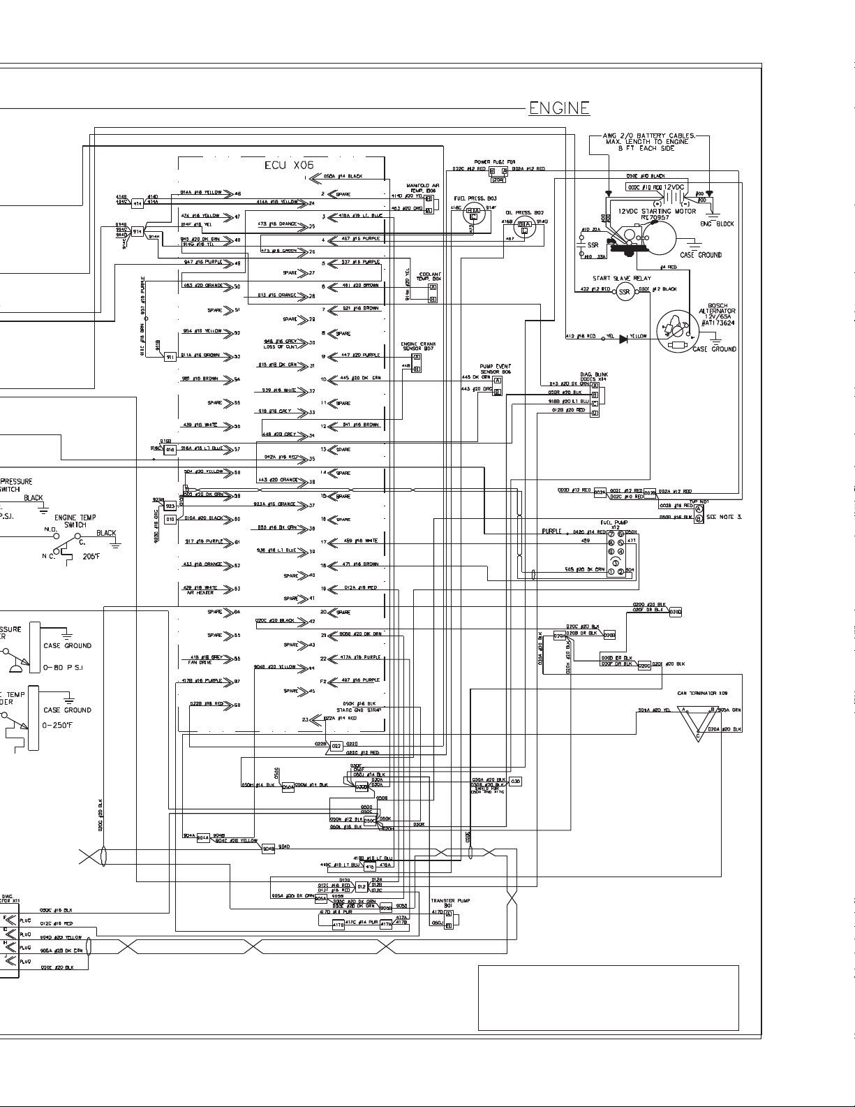
D.C. Wiring - 12 Volt Standard Ground for
M1066A2 and M1066A3
Drawing D-3769B
Page 51
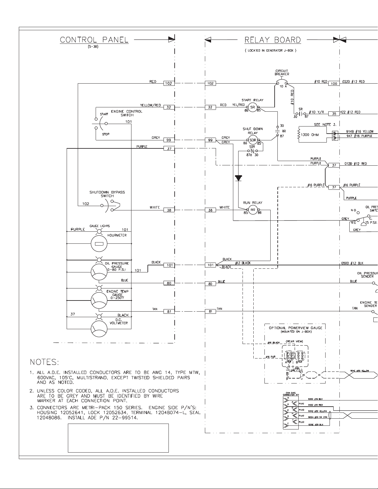
D.C. Wiring - 12 Volt Isolated Ground
for M1066A2 and M1066A3
Drawing D-3770B
Page 52
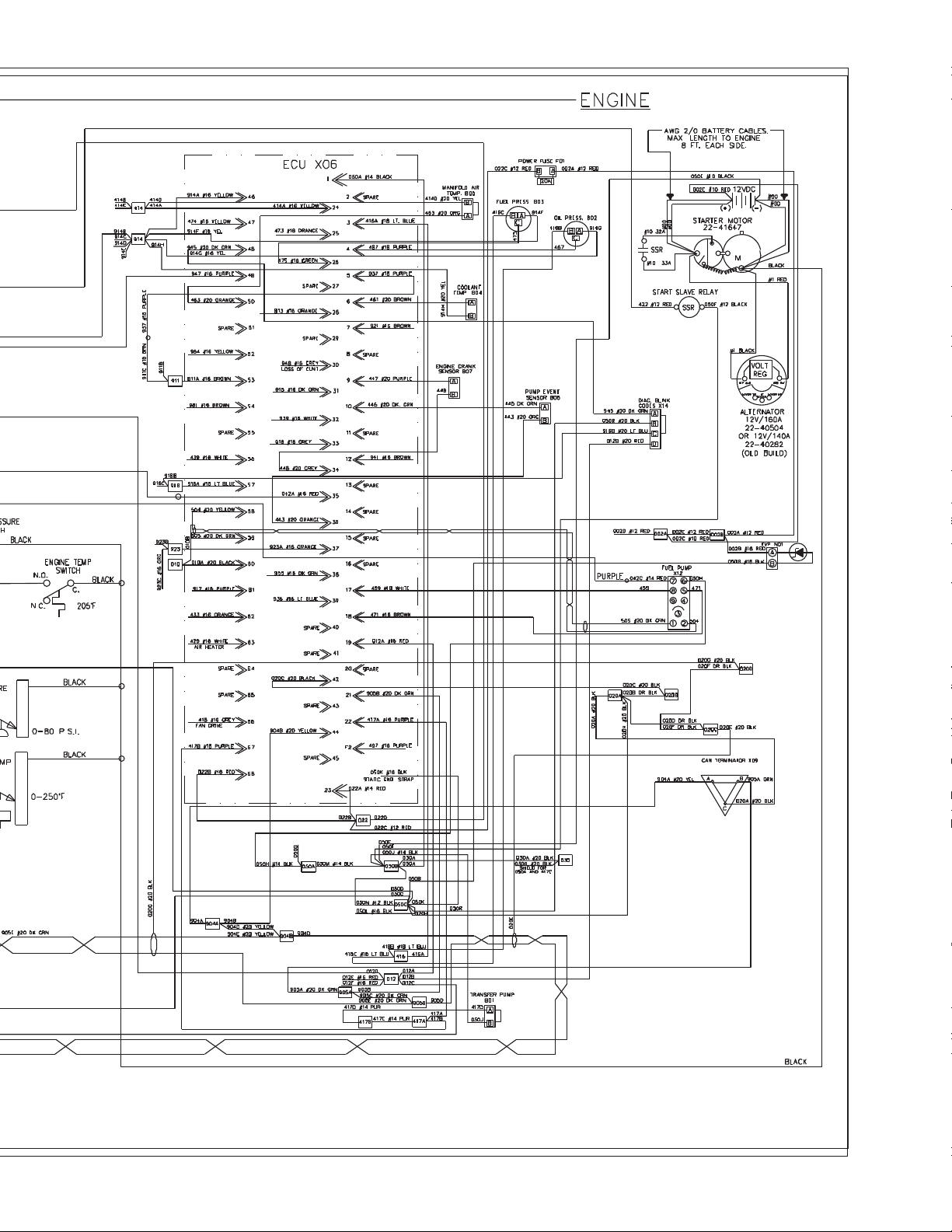
OM2-2 01/10
48
Page 53
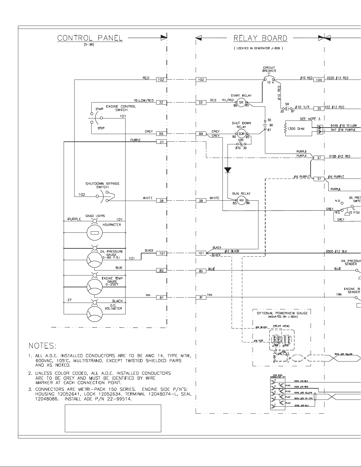
D.C. Wiring - 12 Volt Isolated Ground
for M1066A2 and M1066A3
Drawing D-3770B
Page 54
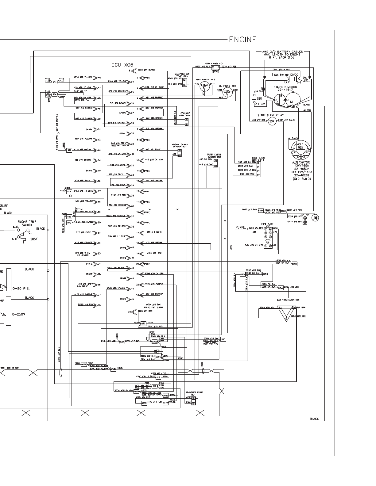
OM2-2 01/10
48
Page 55
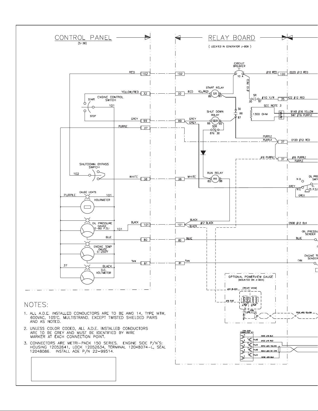
D.C. Wiring - 24 Volt Standard Ground
for M1066A2 and M1066A3
Drawing D-3771B
OM2-2 01/10
49
Page 56
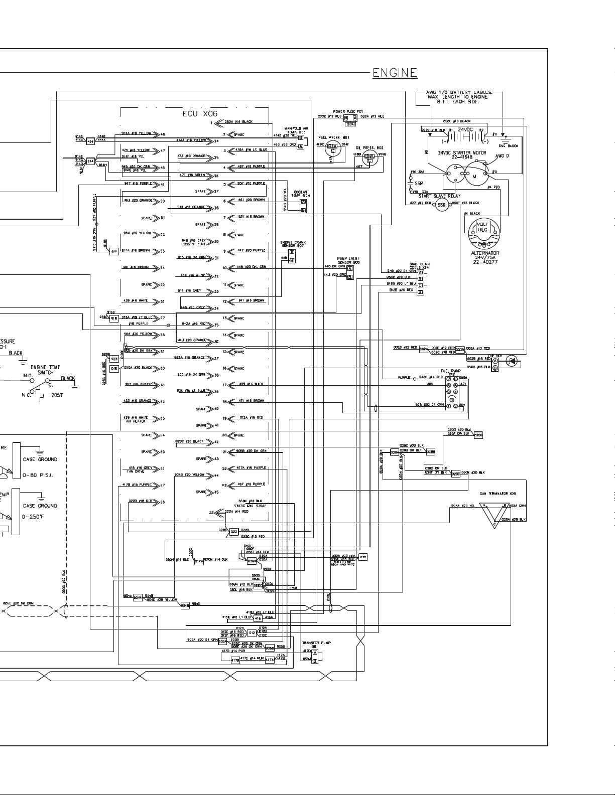
Page 57
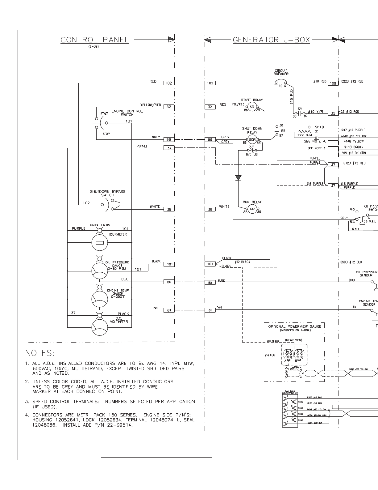
D.C. Wiring - 24 Volt Isolated Ground for
M1066A2 and M1066A3
Drawing D-3772C
Page 58
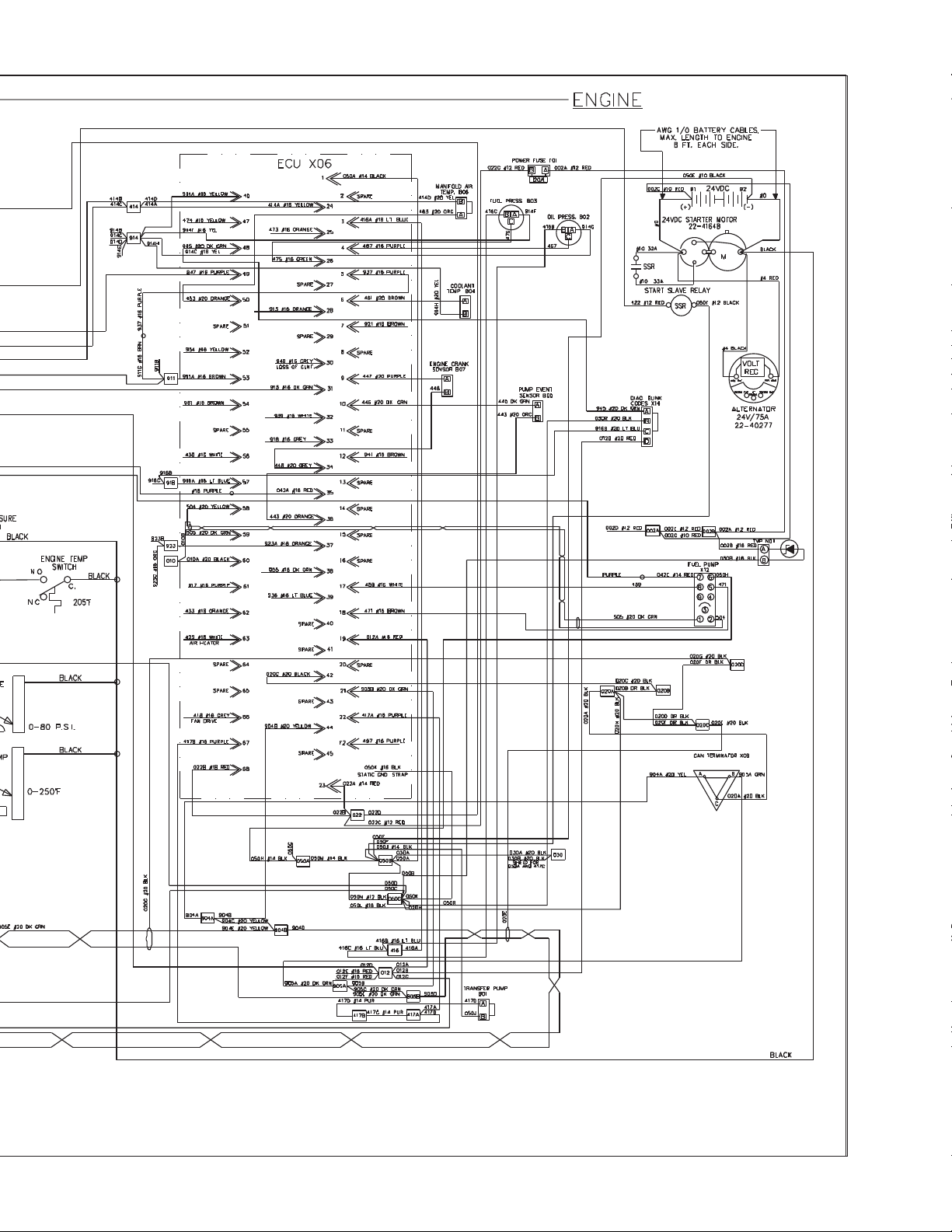
OM2-2 01/10
50
Page 59
On Board Spare Parts
Safety at sea depends on careful preparation, product knowledge, and having the right
tools and parts. Below is a list of parts Northern Lights, Inc. recommends you carry
onboard at all times.
Onboard Parts Kits are available from your dealer.
We consider these minimum quantities. Your vessel's operating conditions may require
more of a given part. Consult your dealer. The example below lists typical items for
either heat exchanged or keel cooled engines.
Item Description Quantity
1 Lube Oil Filter 4
2 Air Filter Element 1
3 Fuel Filter 2
4 Fuel Filter Element 4
5 Fuel Lift Pump 1
6 Injector 1
7 Thermostat 2
8 Thermostat Seal Ring 2
9 Thermostat Cover Gasket 1
10 Rocker Cover Gasket 2
11 Engine Overhaul Gasket Kit 1
12 Zinc Anode* 6
13 Raw Water Pump Impeller* 2
14 Raw Water Pump Cover Gasket* 2
15 Raw Water Pump* 1
16 Raw Water Pump Bearing* 2
17 Coolant Pump Repair Kit 1
18 Coolant Pump Gasket 1
19 Drive Belt 1
20 Workshop Manual 1
*Heat exchanger cooled engines only
OM2-2 06/10
51
Page 60

www.northern-lights.com
4420 14th Ave. NW., Seattle WA 98107
Tel: (206) 789-3880 • 1-800-762-0165 • Fax: (206) 782-5455
Northern Lights and Lugger are registered trademarks of Northern Lights, Inc.
© 2010 All rights reserved. Litho USA.
 Loading...