

Page 1
Rail350V - IP
Installation Guide
Revision 2
1 Safety
This instruction sheet gives details of safe installation and operation of the Rail350V-IP electricity meter. Labels on each
meter give details of equipment ratings for safe operation. Take time to examine all labels before commencing installation.
Safety symbols on the meter have specific meanings as:
Caution Risk of Danger
Refer to Instructions
Risk of Electric Shock
Danger
Safety may be impaired if the instructions are not followed or the meter is used in a manner not
specified by the manufacturer.
Contains no user serviceable parts. Field wiring and commissioning should only be carried out
by qualified personnel, in compliance with applicable national regulations.
e.g. National Electrical Code (NEC) for US; Canadian Electrical Code for Canada
For further Information contact the manufacturer:
Address: Northern Design (Electronics) Ltd: 228 Bolton Road, Bradford, West Yorkshire, BD3 0QW. (UK)
Web: http://www.ndmeter.co.uk
Email: [email protected]
2 Maintenance
The equipment should be maintained in good working order. Damaged equipment must be sent to the manufacturer (or
his authorised agent) for repair. The meter may be cleaned by wiping lightly with a soft cloth. No solvents or cleaning
agents should be used. All inputs and supplies must be isolated before cleaning any part of the equipment.
3 Intended Use
The Rail350V-IP is a precision multi function electricity monitor which measures system power parameters, including kW,
Volts and Amps and displays them on an LCD. Measured parameters may be sent to remote systems for storage or
display using an optional TCP/IP Ethernet communications interface.
The Rail350V-IP is intended for mounting on a standard 35mm “Top-Hat” Din Rail in a standard, secure, electrical switch
enclosure so that only the front display is accessible to the end user after installation.
The safety of any system containing the meter as a component remains the responsibility of
the system manufacturer. After installation in a system, the ratings of the overall system, which
reflect the ratings of the meter, must be visible to the user.
Only the front panel of the Rail350V-IP may remain accessible to the user after installation in a
suitable switch enclosure.
A suitably located and easily reached switch or circuit breaker must be included as part of the
installation. This could, for example, be a safety-interlocking device on the door/front panel of
the electrical enclosure. This switch/circuit breaker must be marked as the disconnecting
device for the equipment and must comply with the relevant requirements of IEC 60947-1 and
IEC 60947-3.
Disconnect / Isolate all supplies before commencing installation.
Page 2
4 Standard Connections
4.1 Current Transducers
Only current transducers which meet the manufacturer’s specifications should be used.
Minimum Current Transducer Specification:
Input Current Range: 0 to 1.2 In (In = nominal rated current in amps)
Output Voltage: 0.33Vac at In
Insulation: 600Vac (Core to secondary conductors)
Cable: Operating Temperature, 105°C (221°F)
Insulated 600Vac
The following list of UL & CE recognised current transducers has been approved for use with the Cube/Rail series of meters:
Part Number Primary Current (XXX) Secondary Window Size
XFR/S0142/XXX 5, 10, 30, 50, 75, 100, 150, 200Amps 0.333Vac 19.1 x 19.1mm(0.75” x 0.75”)
XFR/S0152/XXX 75, 100, 150, 200, 300, 400, 600Amps 0.333Vac 31.8 x 31.8mm (1.25” x 1.25”)
XFR/S0162/XXX 100, 200, 300, 600, 800, 1000, 1500Amps 0.333Vac 50.8 x 50.8mm (2.0” x 2.0”)
XFR/S1142/XXX 5, 10, 30, 50, 70, 100, 150, 200Amps 0.333Vac 19.1 x 19.1mm(0.75” x 0.75”)
XFR/S1152/XXX 50, 70, 100, 150, 200, 250, 300, 400, 600Amps 0.333Vac 31.8 x 31.8mm (1.25” x 1.25”)
XFR/S1162/XXX 100, 200, 300, 400, 600, 800, 1000, 1200, 1500Amps 0.333Vac 50.8 x 50.8mm (2.0” x 2.0”)
XFR/S1172/XXX1 400, 600, 800, 1000, 2000, 3000Amps 0.333Vac 127.0 x 76.2mm (5.0” x 3.0”)
Current Transducer (CT) connections are not galvanically isolated from the voltage inputs and
must therefore not be accessible to the operator after installation. Installed CT cables and any
extensions to these, must not be accessible to the user.
NOTE 1: Model XFR/S1172/XXX is only approved for use up to an ambient temperature of 30ºC (86°F). All other models
are approved for use up to 55ºC (131°F).
If the current transducer secondary cables require extending, care must be taken to avoid pickup of electrical interference.
With suitable low capacitance screened cables, the cable can be extended to 100m (328ft) or more.
Extensions to the supplied current transducer cables must ensure all connections remain
inaccessible to the operator after installation.
All cables and connections must meet the minimum specifications provided.
4.2 Voltage Connections
To maintain proper insulation from the mains supply, the neutral wire should only be used in
power networks where the system neutral is protectively earthed at some point.
4.2.1 Voltage Cables
4.2.2 Auxiliary Mains Supply
The meter is powered from an auxiliary mains supply which is required to energise the metering circuit and display. This
can be connected in parallel with one of the measurement phase voltages if it is rated correctly.
Voltage cables must be rated for safe use in the electrical enclosure which houses the meter
(e.g. UL1015) and must meet the following minimum specification: Temperature: 105°C
(221°F), Insulation 600Vac.
Ensure the auxiliary mains supply L-N is powered from a correctly rated and fused AC source
as specified on the meter label.
4.2.3 Voltage Terminals
Voltage: 277Vac (2-3, 3-4)
480Vac (4-5, 5-6)
Cable: 30-11 AWG, Stripped 6.5 to 7.0mm (0.24” to 0.28”)
Torque: 0.5Nm (4.4in lb)
Page 3
4.2.4 Voltage Fuses
Fuses (US/Canada)
Rated Voltage Type Rupture In (A) Standards
≥ 500Vac
Fast 1.0A UL248 (US)
C22.2 No. 248 (CAN)
Fuses (Other Countries)
Rated Voltage Type Rupture In (A) Standards
≥ 500Vac
Fast 1.0A IEC 60269 - 2
4.2.5 Auxiliary Mains Fuses
Fuses (US/Canada)
Rated Voltage Type Rupture In (A) Standards
≥ 250Vac
Fast 0.1A UL248 (US)
C22.2 No. 248 (CAN)
Fuses (Other Countries)
Rated Voltage Type Rupture In (A) Standards
≥ 250Vac
Fast 0.1A IEC 60269 - 2
4.3 Communications Options
The Ethernet communication port is safety isolated from the measurement voltages at a minimum of 3.5kV.
Communications cables running within an electrical enclosure may come close to high voltages
and therefore must be insulated to the following minimum specification:
Safety Compliant: e.g UL1015; Operating Temperature: 105°C (221°F); Insulation 600Vac
4.3.1 Ethernet Output (Optional)
Connection: RJ45
Cable: Cat5e FTP (Foil screened)
Speed: 10/100 BaseT
For installation & settings of Ethernet, refer to the IP Meter Operating Manual Rev 1.07
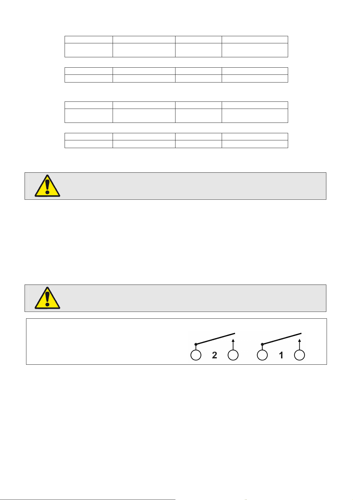
4.4 Digital Outputs
Two digital outputs are available on the Rail350V-IP in the form of isolated volt free normally open contact pairs. The
contacts are isolated from the mains input circuits (3.5kV) and at 50V between outputs (Digital Outputs 1 to 2).
Digital outputs may be configured using the embedded web pages to provide Under/Over alarm status based on a
selected measurement parameter and programmable limits.
Digital output cables running within an electrical enclosure may come close to high voltages
and therefore must be insulated to the following minimum specification:
Safety Compliant: e.g UL1015; Operating Temperature: 105°C (221°F); Insulation 600Vac
Digital Outputs
Voltage
Current
Load
Tightening
Temperature
70Vdc/33Vac max
100mA (ac/dc) max
5 Watts max
< 0.25Nm
Terminals 110°C (230°F) max
Page 4
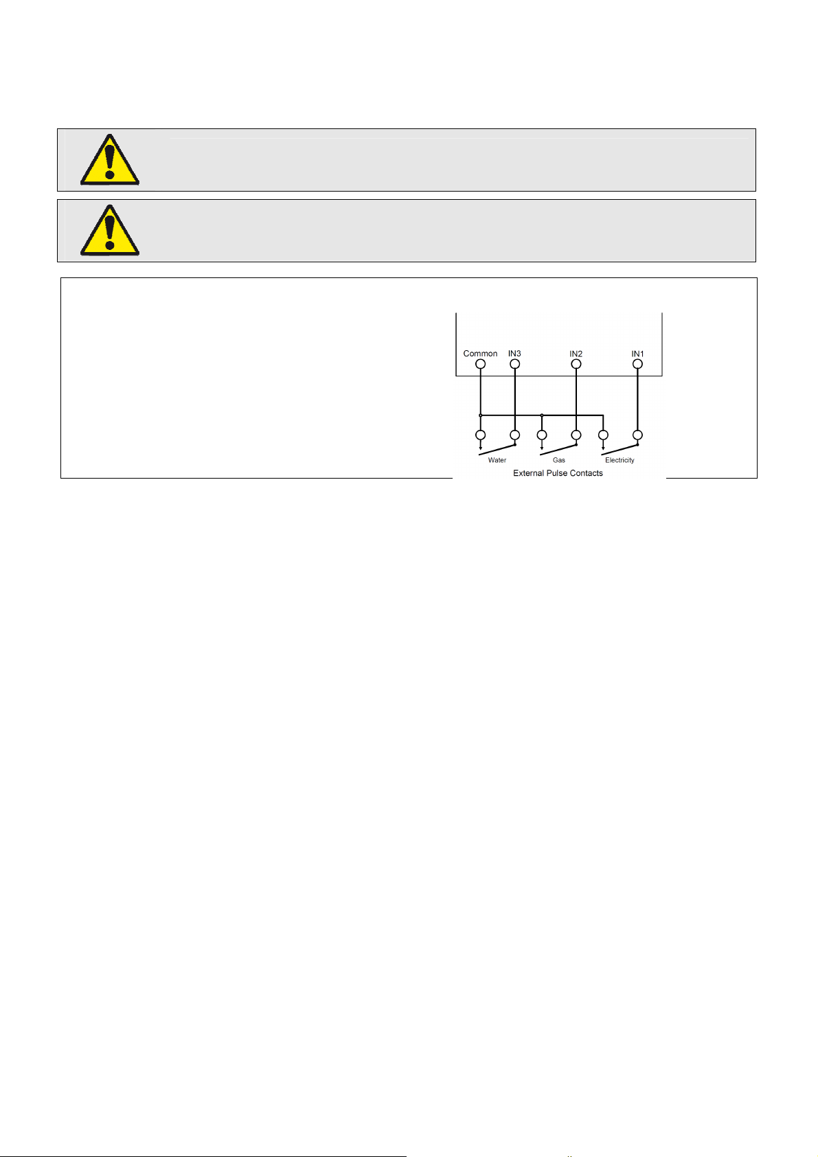
4.5 Digital Inputs
Three isolated (3.5kV) digital inputs are available on the Rail350V-IP. These inputs may be connected to external utility
meter pulse outputs such as electricity, water, gas meters etc. Pulses detected at the digital inputs are accumulated by
the Rail350V-IP and may be logged and profiled in the same way as energy registers monitored directly by the meter.
Risk of Equipment Damage
Only connect digital inputs to volt free contacts – DO NOT APPLY AN EXTERNAL VOLTAGE
Digital input cables running within an electrical enclosure may come close to high voltages and
therefore must be insulated to the following minimum specification:
Safety Compliant: e.g UL1015; Operating Temperature: 105°C (221°F); Insulation 600Vac
Digital Inputs
Voltage
Current
Tightening
Temperature
5Vdc max (internally supplied)
2mA dc max (per Input)
< 0.25Nm
Terminals 110°C (230°F) max
Page 5
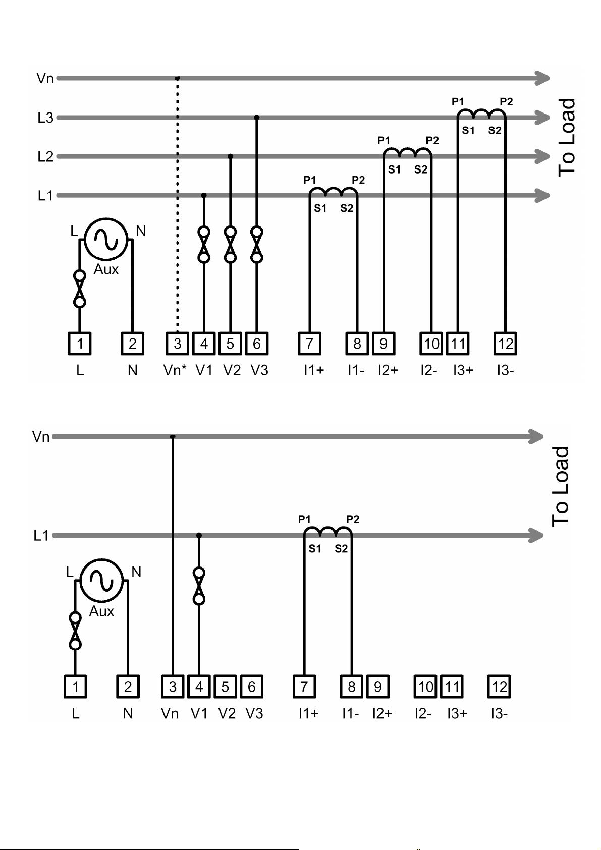
4.6 Typical Connections
3-Phase 3 or 4-Wire (*Optional Neutral)
Single Phase
NOTE: For single phase systems it is advisable to link out unused current inputs (9-10 and 11-12) with a short insulated
wire link. This prevents unwanted noise affecting meter readings.
Page 6
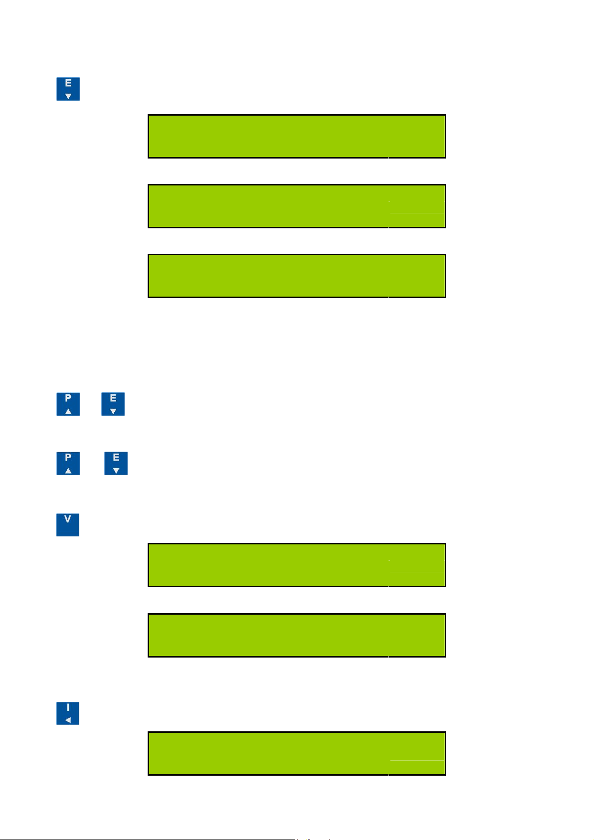
5 Operation
5.1 Energy Displays
Press to select kWh kvarh and Hours Run display pages.
1234567.8
kWh
Active Energy Register
(Note 2)
rh
1234567.8
Hours Run
(Note 1)
kVArh
1234567.8
Reactive Energy Register
Note 1: The Hours Run register accumulates the total time during which the average 3-phase load current exceeds a
preset level. This is always displayed with a resolution of 0.1hour.
The percentage level of (I1+I2+I3) at which the Hours Run register accumulates is user programmable from 1% to 100%
of full scale current and can be set through the programming menu.
Press and together and hold for 2 seconds to reset the hours run register. The reset of Hours run register
cannot be disabled.
Note 2: Scaling of the energy registers is set by the nominal input currents and voltages and remains constant during
operation of the meter. Energy registers will each accumulate from zero to 99,999,999 then restart from zero.
(Note 2)
Press and together and hold for 2 seconds to reset the displayed value. This feature is disabled by default.
Refer to Rail350 option links guide to enable. The reset function works simultaneously on kWh or kvarh registers.
5.2 Voltage Displays
Press to select from the following displays;
V
P1 230.0
Phase-n Voltages 1 - 3
(Note 3)
V
L1 400.0
Line-Line Voltages 1 – 3
5.3 Current Displays
Press to select from the following displays;
(Note 3)
A
P1 200.0
Phase 1 – 3 Current
Page 7
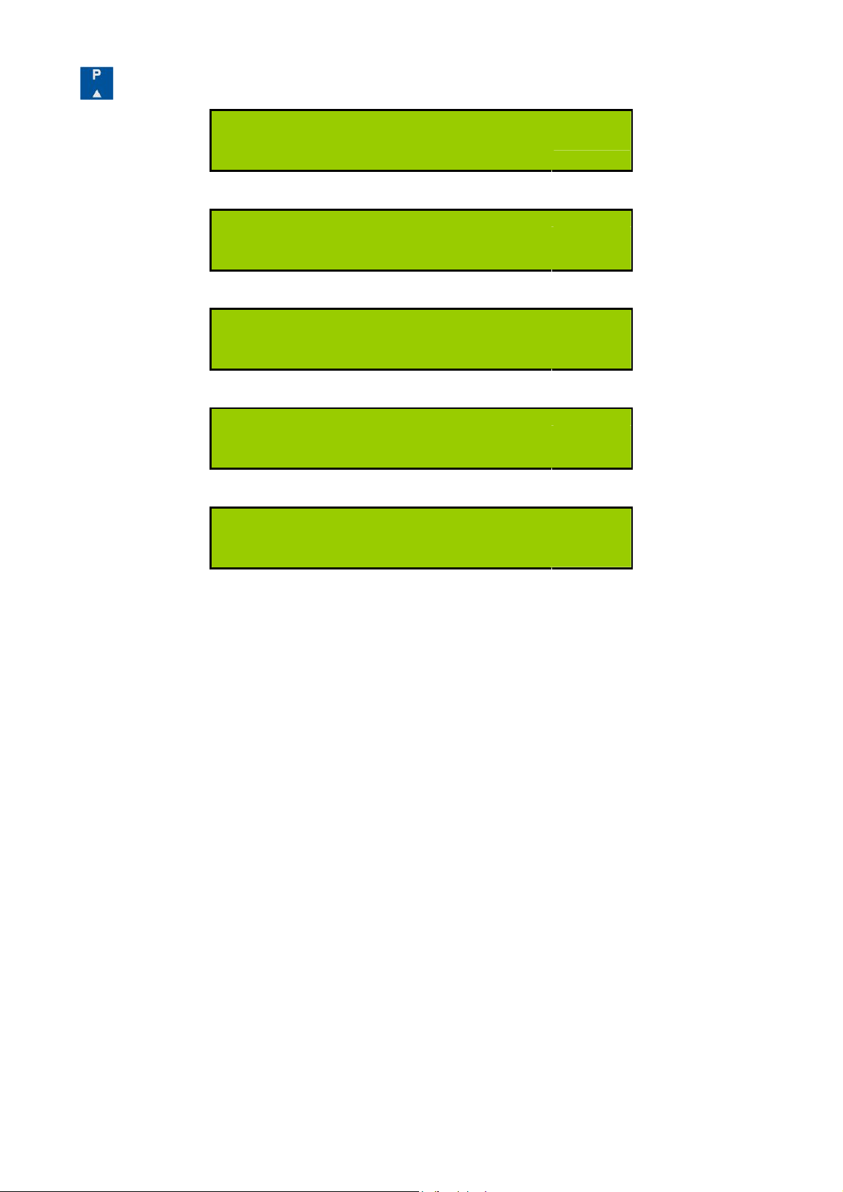
5.4 Power Displays
Press to select from the following displays;
System Active Power
F 50.0
Frequency. Hz (Phase 1 voltage)
PFc 1.00
kW
144.00
System Power Factor (C=Capacitive)
(Note 3)
kW
P1 48.00
Phase 1-3 Active Power
(Note 3)
PF1c 1.00
Phase 1-3 Power Factor (C=Capacitive)
NOTE 3: Some display pages are removed in Balanced Voltage Mode (Refer to section 6.7).
(Note 3)
Page 8
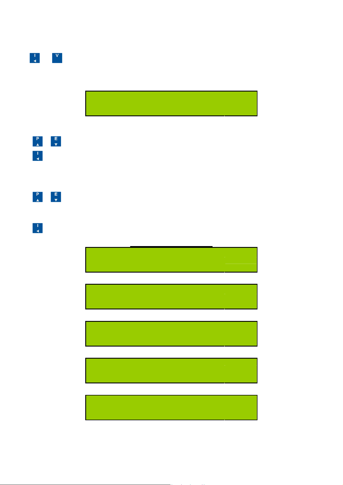
6 Programming
6.1 Programming Menu
To enter programming mode:
Hold and together for 5 Seconds.
A Security Code may be required before changes to programmed parameters are allowed. This is only required if a
Security Code greater than zero is set via serial communications. This is then stored in non-volatile memory during
power interruptions.
Pin 1234
4-Digit Security Code
To Enter A Security Code:
Press or to change each digit. (Lowest significant digit first).
Press to select next most significant digit.
When a valid code is input the programming menu is displayed.
To change a Programmable Value:
Press or until the required value is set.
To Move to The Next Setting:
Press until the next page in the list is displayed. Parameters are set in the following order:
Program Menu Pages
A
Ct 150
Current Sensor Primary
V
Un 480
Nominal Line-Line V (or PT Primary)
(Note 4)
kWh
PLr 0.1
Output Pulse Rate
PLt 0.1
Pulse On Time
Pto 9999
Pulse Output Test
Page 9
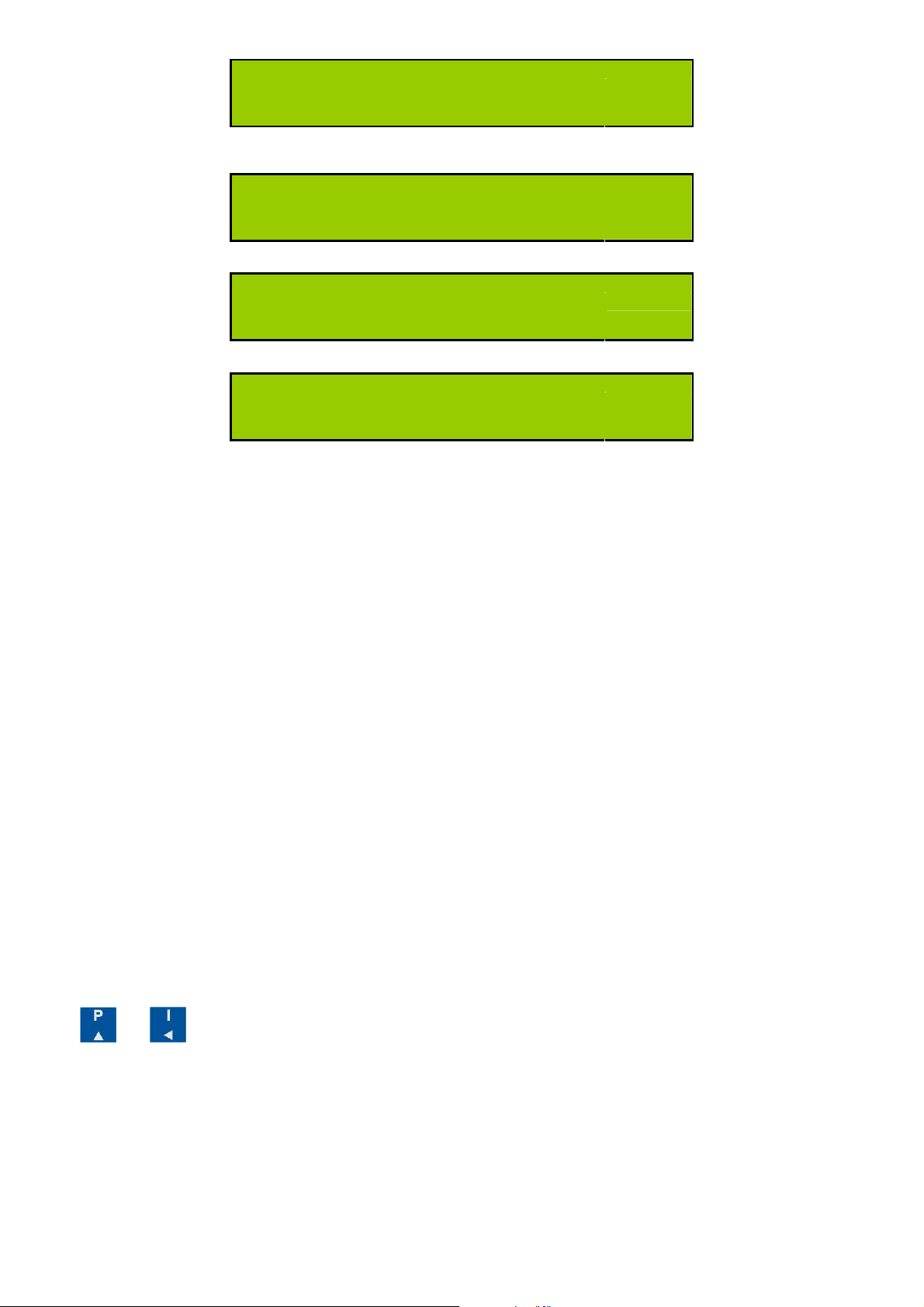
Hr 20
Hours Run Trip Point (Percent Amps)
TrUE 3Ph
Voltage Input Mode
Auto rot
CT Auto Rotation Mode
Storing
Changes Are Stored to Non-Volatile Memory
After the last parameter is set the new values are stored and the meter continues to measure with the new settings.
6.2 Current Sensor Type Selection (CT)
Current sensor types are selected from a table of preferred types identified by their nominal primary current rating. The
following types may be selected.
Note:
Current sensors MUST be from the PowerRail350V range of input devices supplied by the
manufacturer. Use of other sensors may affect accuracy & safety
5, 50, 100, 150, 400, 800.
6.3 Nominal Line-Line Voltage Selection (Un)
The nominal line-line voltage of the measured supply system may be programmed.
For systems without potential transformers (PTs) this should be the same as the nominal input of the meter as specified
on the rating label (e.g. 480V).
For systems with PTs fitted this should match the nominal primary rating of the PT. The preferred values are:
11, 40, 48, 100, 110, 208, 400, 480, 600, 800, 1000, 1100, 2200,
3300, 4000, 4400, 6600, 7500, 10000, 11000, 15000, 22000, 33000, 66000
Note 4
i.e. for 110V, 208V, 230V system. LEAVE Un (Voltage Transformer Primary Setting) TO 480V ONLY.
If external VT is used, alter the voltage transformer primary setting as stated in the following examples.
For 11000/110V VT, alter the setting to 48000 (multiplying factor: 11000 / 110 = 100 i.e. 480X100)
For 6600/110V VT, alter the setting to 28800 (multiplying factor: 6600 / 110 = 60 i.e. 480X60)
Fine Adjust Mode allows values other than those provided by the default tables to be set. To enter/exit Fine Adjust
Mode:
Hold and together for 2 Seconds while setting Un. Fine Adjust Mode is indicated by a decimal point after
“Un”.
: If external VT is not used, DO NOT ALTER the voltage transformer primary setting for any other system voltage
6.3.1 Fine Adjust
6.4 Pulse Rate Selection Table (Counts)
Pulse values are displayed scaled as 1 count of energy.
1, 2, 5, 10, 100, 1000
6.5 Pulse On-Time Selection Table
100ms ,200ms, 500ms, 1s, 2s, 3s, 5s, 10s, 20s
Page 10
6.6 Pulse Output Test
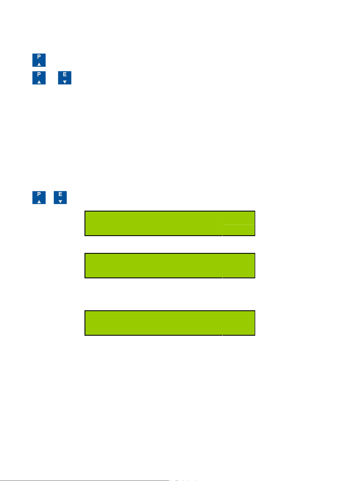
This feature allows the pulse output hardware and external system connections to be commissioned without a measured
load. The LCD shows Pto (off) and Ptr (run) and the number of test pulses. The test pulse rate is set automatically
dependant on the programmed pulse length (maximum 0.5Hz).
Press to start/stop the test pulses on both outputs.
Press and together to stop the test pulses and simultaneously reset the test counter.
6.7 Voltage Input Mode Selection
In “Balance Voltage Mode” the PowerRail350 may be connected to a single voltage source in place of the three phases
normally required for full accuracy measurement.
When Balanced Voltage Mode is enabled the voltage measured on phase 1 is copied to phases 2 & 3 and all three
power-factors are assumed to be unity (1.00). In this mode, the voltage connected to phase 1 on the meter may be fed
from any of the 3-Phase system voltages.
This connection is valid for loads with a near unity power-factor (PF=0.95 equates to an error of 5%) and balanced 3Phase voltages.
The combination of Split Core Current Sensors and Balanced Voltage Mode allows for rapid commissioning where
access cannot be made to 3-Phase terminations. At a later date when access is possible, for example during planned
maintenance, the meter may be connected safely to the 3-Phase voltages and Balanced Voltage Mode de-selected.
Press or to toggle between Balanced Voltage Mode and True 3-Phase Measurement Mode.
TrUE 3Ph
True 3-Phase Measurement Mode
bAL 3Ph
Balanced Voltage Mode
In Balance Voltage Mode some display menu pages are removed as they have little or no meaning and voltage is
displayed as:
V
bAL 230.0
Voltage Display in Balanced Voltage Mode
Single Phase kW, Power Factor and kvarh displays are removed while Balanced Voltage Mode is enabled.
Page 11
6.8 CT Auto Rotation Mode
When “CT Auto Rotation Mode” is selected, the orientation of each Current Transformer (CT) on its respective cable
becomes irrelevant. It is therefore possible to pass the cable through the centre of the CT in either direction. In this mode
current direction is ignored and all power is assumed to be feeding a load (import).
When “CT Auto Rotation Mode” is de-selected (“True Rotation Mode”) current direction is monitored and measurement
of import and export power is provided.
In both modes it is essential to place each CT on the correct phase conductor associated with the relevant phase voltage:
Therefore link CT1 with V1, CT2 with V2, CT3 with V3.
PowerRail350 meters are normally supplied with “CT Auto Rotation Mode” selected. In order to detect Positive and
Negative power values in all four quadrants it is necessary to de-select “CT Auto Rotation Mode”.
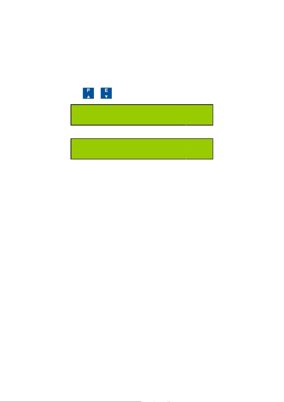
In the programming Menu Press or to toggle between CT Auto Rotation Mode and True Rotation Mode.
Auto rot
CT Auto Rotation Mode
truE rot
True Rotation Mode
NOTE
assumed to be unity and current phase and direction is ignored.
: CT Auto Rotation Mode is not available when Balanced Voltage Mode is selected as all Power Factors are
Page 12
7
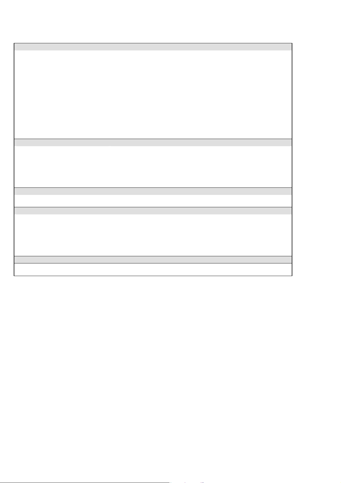
Specification
INPUTS
System
Voltage Un
Current Sensors
Output @ Nominal In
Accuracy
Phase Error
Measurement
Range
Frequency Range
Voltage Burden
Overload
DISPLAY
Type
Data Retention
Format
Scaling
Legends
AUXILIARY SUPPLY
Standard
Load
METER ACCURACY All errors ± 1 digit
kWh
Kvarh
kW & kVA
kvar
Amps & Volts
PF
Neutral Current
OVERALL METERING ACCURACY
5A-50A Models
Other Models
3 Phase 3 or 4 Wire Unbalanced Load or Single Phase
480/277V. 3 Phase 3 or 4 Wire
0.333Vac
±1% (0.1In – 1.2In)
5A-50A Models <2.5° at 0.5In. Other models <2.0° at 0.5In
Voltage 20% to 120% Un (Max 520V L-L, 300VL-n)
Current 0.2% to 120%
Fundamental 45 to 65Hz
Harmonics Up to 30th harmonic at 50Hz
Individual to the 15th
<0.1VA per phase
Voltage x4 for 1 hour
Current x 2 Continuous
Custom, Supertwist, LCD
10 years min. Stores kWh & Meter set-up
8 x 6.66mm (0.31” x 0.26”) high digits with DPs & 3.2mm (0.13”) legends
Direct reading. User programmable CT & VT
CT Primary programmable from 5A to 25kA
VT primary programmable from 11V to 440kV
Wh, kWh, MWh etc. depending on user settings
100-240Vac 45-65 Hz
5 Watt Max.
Better than Class 1 per EN 62053-21 & BS 8431
Better than Class 2 per EN 62053-23 & BS 8431
Better than Class 0.25 IEC 60688
Better than Class 0.5 IEC 60688
Class 0.1 IEC 60688 (0.01In – 1.2In or 0.1Un – 1.2Un)
±0.2° (0.05In – 1.2In and 0.2Un – 1.2Un)
Class 0.5 IEC 60688 (0.05In – 1.2In)
Better than Class 2 Meter with Class 1 CTs
Better than Class 1 Meter with Class 1 CTs
Page 13
Digital Outputs
Function
Pulse Period
Rise & Fall Time
Type
Contacts
Isolation
Digital Inputs
Function
Pulse Period
Wetting Voltage
Wetting Current
Isolation
ETHERNET (Option)
Electrical
Data Rate
Protocol
Connection
Isolation
GENERAL
Temperature
Humidity
Environment
MECHANICAL
Enclosure
Material
Dimensions
Weight
SAFETY
Conforms to
Programmable alarm status
0.1 sec. default; Settable between 0.1 and 20 sec
< 2.0ms
N/O Volt free contact. Optically isolated BiFET
100mA ac/dc max ; 70Vdc/33Vac max ; 5W maximum load
3.5kV 50Hz 1 minute
Counter Inputs from external volt-free contacts
50mS minimum
5.0V dc maximum (Internally supplied)
2mA dc maximum (Internally supplied)
3.5kV 50Hz 1 minute
IEEE std 802.3. 2000 Edition
10 Mbits/s
TCP, UDP, DHCP, FTP, TFTP, HTTP, SNTP, SNMP, Modbus TCP
10/100 Base T - RJ45
3.5kV
Operating -10°C to +55°C (14°F to 131°F)
Storage -25°C to +70°C (-13°F to 158°F)
< 75% non-condensing
IP20 (when correctly mounted, as described, in a panel)
Altitude <2000m (6561ft)
DIN 43880, 6-Modules Wide
Noryl® with fire protection to UL94-V-O. Self extinguishing
106 x 90 x 58mm (Cut out 106 x 45mm)
4.17” x 3.54” x 2.28” (Cut out 4.17” x 1.77”)
~ 150 gms
EN 61010-1 Overvoltage Category III & BS 8431
E. & O. E.
© Northern Design (Electronics) Ltd, October 2016
 Loading...