

Page 1
PowerRail300 Operating Guide
December 2007
1 Safety
This instruction sheet gives details of safe installation and operation of
the Rail300 electricity meter. Safety may be impaired if the
instructions are not followed. Labels on each meter give details of
equipment ratings for s afe operation. Take time to examine all labels
before c ommencing installation. Safety symbols on the meter have
specific meanings.
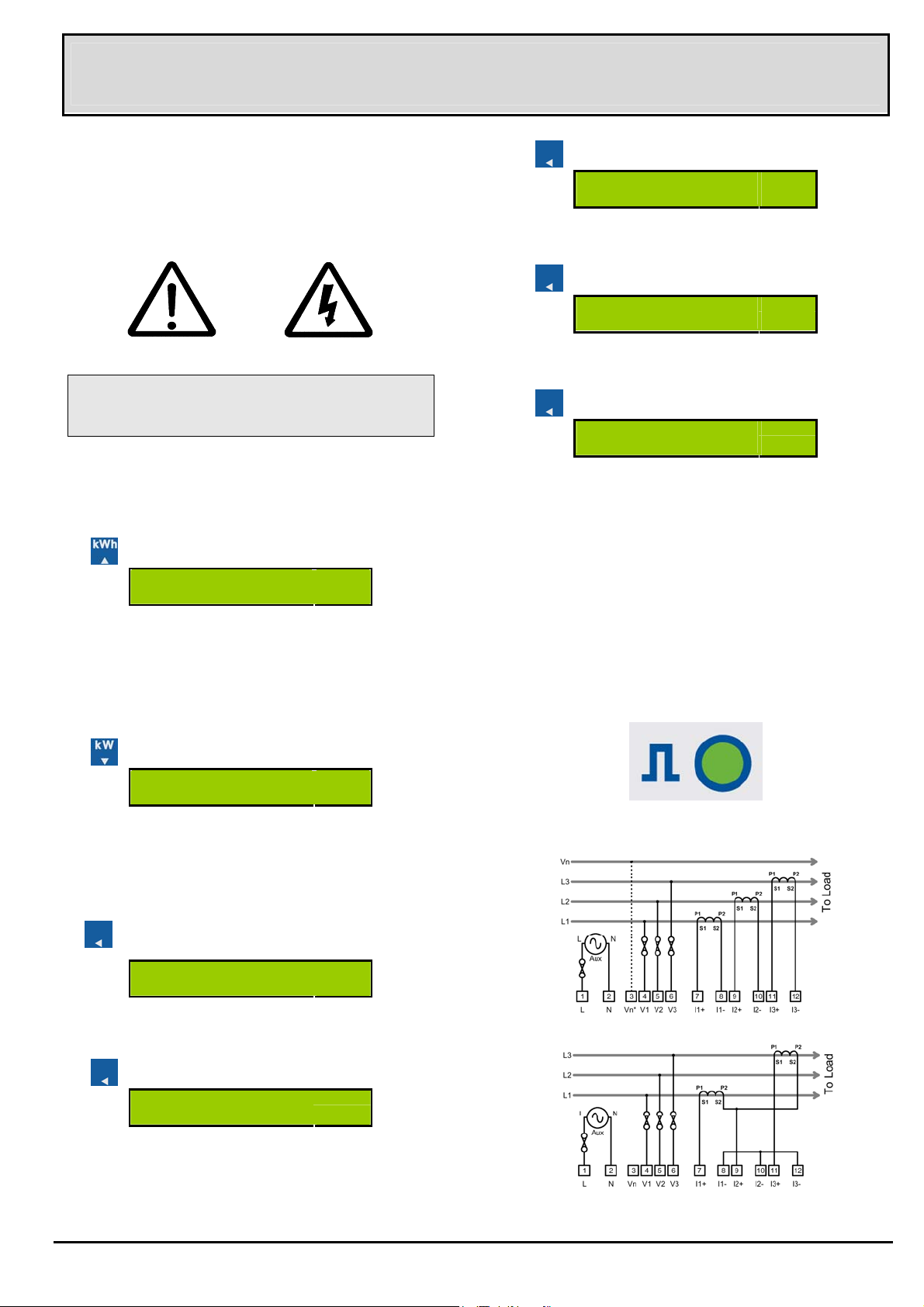
Press
PLr indicates the amount of energy accumulated between each pulse
output.
.
PLr 0.1
Output Pulse Rate
kWh
Refer To User Manual Risk of Electric Shock
WARNING
The meter contains no us er serviceable parts. Installation and
commissioning should only be c arried out by qualified
personnel
Further information is available at http://www.ndmeter.co.uk.
2 Operation
2.1 Energy Display
Press
1234567.8
Energy Register
Scaling of the energy register is set by the nominal input currents and
voltages and remains constant during operation of the meter.
If no keys are pressed, the meter will automatically revert to this page
after 60 seconds. The energy register will accumulate from zero to
99,999,999 then restart from zero.
2.2 Power Display
kWh
Press
PLt indicates the length of time (in seconds) the output pulse contacts
remain short circuit f or each pulse.
Press
OPt Is a code indicating which factory fit options are supplied on an
individual meter. This information may be requested when contacting
technical support.
.
PLt 0.1
Pulse On Time
.
OPt 1011
Options Fitted
2.4 Pulse Output
An isolated pulse output is provided f or connection t o exter nal systems
such as Building Energy Management Systems (BEMS), data loggers,
remote counters etc.
A single puls e occurs for each unit of energy on the display (eg 1 pulse
per 0.1kW h). The pulse rate (amount of energy associat ed with each
pulse) and pulse length may be set to suit the external system.
2.4.1 Pulse LED
A light emitting diode (LED) on the front panel of the instrument pulses
ON during each output pulse.
Press .
144.00
Power Register
The instantaneous power display may show negative values indicating
export power or incorrectly wired inputs.
kW
2.3 Setup Display Menu
Each meter is configur ed to operate in a specific system. The meter
settings may be displayed on the LCD in the Setup Display Menu.
Hold
The CT value should match the Nominal Primary rating of the current
transformers fitted with the meter.
Press
If no external potential transformer (PT) is fitted Un is the Rated
Nominal Line-Line Voltage as detailed on the meter label.
If a PT is fitted, its secondary voltage should match the Rated Nominal
Line-Line Voltage of the meter, Un is then programmed as the
Nominal Rated Primary Voltage of the PT.
for 5 Seconds.
Ct 200
Current Transformer Primary
.
Un 400
Nominal Line-Line Voltage (or PT Primary)
A
V
Pulse Output Indicator
3 Standard Connections
3-Phase 3 or 4-Wire (*Optional Neutral)
3-Phase 3-Wire
© Northern Design (Electronics) Ltd 7 December 2007 E & O E Page 1 of 2
Page 2
4 Programming
4.1 Programming Menu
To enter programming mode:
Hold
The first programmable parameter, CT Primar y, is dis played.
To change a value (eg CT Primary):
Press or until the requir ed value is set.
To Move to The Next Setting:
and together for 5 Seconds.
Ct 200
A
5 Display Scaling
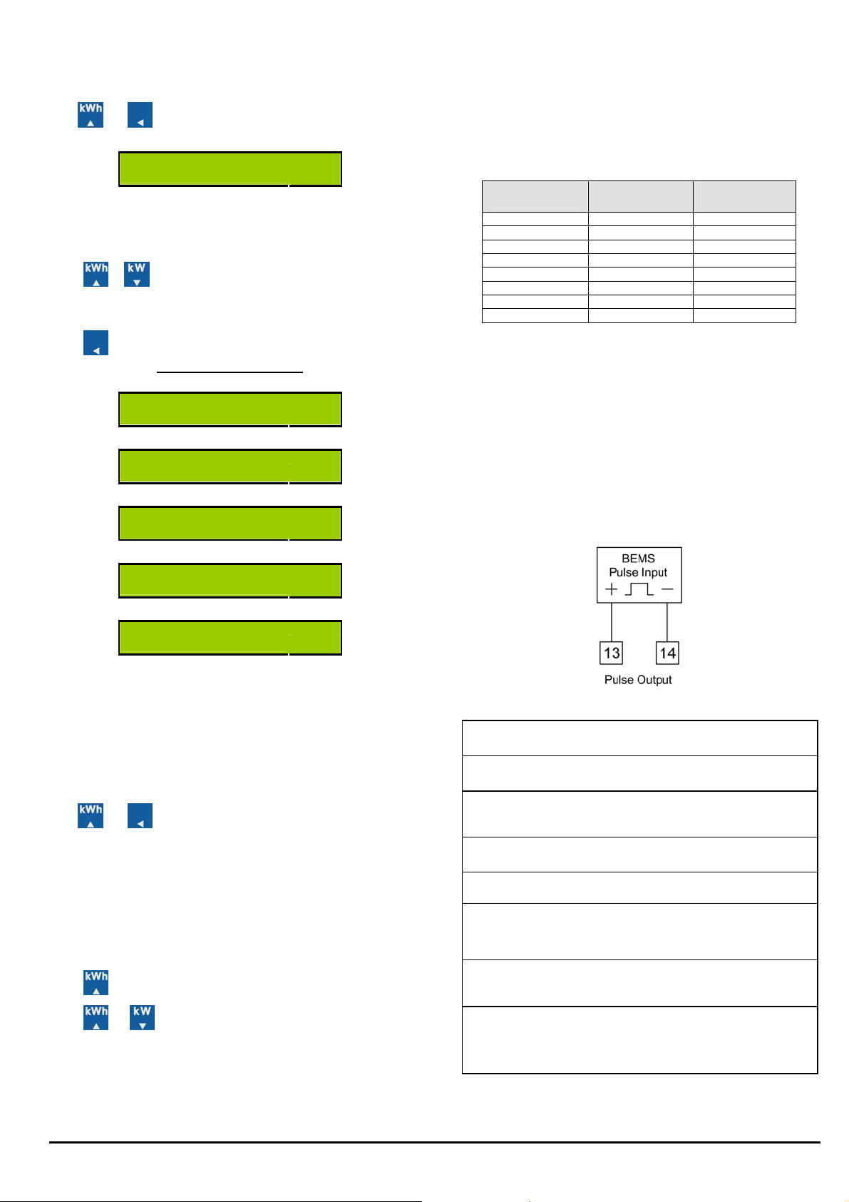
The units, Wh, kWh or MWh and the position of the decimal point for
the energy/power displays are automatically set dependant on the CT
and Un settings for the meter.
The nominal 3-phase input for the meter is defined as:
Wnom = 1.732 x Un x CT
The display pages are scaled as f ollows:
Wnom
< 243 W 0.1W 0.001 kWh
< 2.43 kW 0.1W 0.001 kWh
< 24.3 kW 0.001 kW 0.01 kWh
< 243 kW 0.01 kW 0.1 kWh
< 2.43 MW 0.1 kW 1 kWh
< 24.3 MW 1 kW 0.01 MW h
< 243 MW 0.01 MW 0.1 MWh
> 243 MW 0.1 MW 1 MWh
kW
Resolution
kWh
Resolution
Press until the next parameter is displayed.
Program Menu Pages
Ct 200
Current Transformer Primary
Un 400
Nominal Line-Line V (or PT Primary)
PLr 0.1
Output Pulse Rate
PLt 0.1
Pulse On Time
Pto 9999
Pulse Output Test
After the last parameter is set the new values are stored and the meter
continues to measure kWh with the new settings.
A
V
kWh
4.2 Fine Adjust
CT Primary and Nominal Voltage settings are selected from a table of
preferred values. This reduc es the time to program these parameters
to industry standard values.
Fine Adjust Mode allows values other than those pr ovided by the
default tables to be s et. To enter/exit Fine Adjust Mode:
Hold and together for 2 Seconds while setting CT or Un.
Fine Adjust Mode is indicated by a decimal point immediately after
the parameter type (ie. “CT.” or “Un.”)
4.3 Pulse Output Test
This feature allows the pulse output hardware and external s ystem
connections to be commissioned without a measured load. The LCD
shows Pto (off) and Ptr (run) and the number of test pulses. The test
pulse rate is set automatically dependant on the programmed puls e
length (maximum 0.5Hz).
Press
Press
simultaneously reset the test counter.
to start/stop the test pulses.
and together to stop the test pulses and
6 Mounting On A Rail
The Rail300 conforms to DIN 43880, 6 Modules wide. The unit is
therefore compatible with a number of standard distribution systems
with 45mm cut-outs. The meter should be mounted on a 35mm
symmetrical (“top-hat”) DIN rail of minimum length 106mm.
7 Pulse Output Connection
The pulse output takes the form of an is olated volt free normally open
contact pair.
The contacts are isolated from all other circuits (2.5kV / 1 minute).
The puls e can be used as an input to a remote counter, pulse logger,
building energy management system etc.
8 Specification
Aux Supply
Input Voltage
Input
Currents
Accuracy
LCD Display
Pulse Output
Environment
Other
Nominal 230Vac ±15%, 45-65Hz, 1W max.
Optional 115Vac ±15%.
Isolation 2.5kV (1 minute)
Un 400V Line-Line. Range 20%-120% Un
Burden 0.1VA / Phase. Overload 2xUn Continuous.
Other nominal voltages are available to order.
Nominal Ib = 5A. Range 0.2%-120% Ib
Burden 0.1VA / Phase. Overload 40xIb (1 sec)
Isolation 2.5kV (1 minute)
Optional Ib = 1A
KWh: Class 1.
EN62053-21 & BS8431 (2% - 120% Nominal Load)
KW: 1% Rdg (5% - 120% Nominal Load)
LCD 8 Digits h=6.7mm + Legends h=3.2mm.
kWh Memory 10 years without power.
Normally open volt free contacts
1 pulse per energy increment.
Pulse rate and length selectable.
Contacts: 100V ac/dc, 100mA, 5W max
Isolation 2.5kV for 1 minute.
Operate-10°C > T < 65°C. RH < 75% Non
Condensing
Storage- 25C > T < 75C
IP 54
Size: 106 x 90 x 58mm (Cut out 106 x 45mm)
DIN Rail: DIN EN 50022, 35mm. L=106mm (min)
Case: DIN 43880, 6 Modules Wide
Materi al: Noryl UL94V0 Self Extinguishing
Terminals: Rising Cage 0. 25mm
Weight: Approx 250g
2
to 4.0mm2
© Northern Design (Electronics) Ltd 7 December 2007 E & O E Page 2 of 2
 Loading...