

Page 1
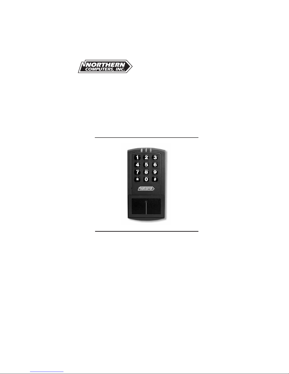
EntryProx
™
Quick Reference
Installation Guide
TD1131 rev0800
Page 2

EntyProx
™
Installation Introduction
Table of Contents
Introduction . . . . . . . . . . . . . . . . . . . . . . . . . . . . . . . . .i
Product Overview . . . . . . . . . . . . . . . . . . . . . . . . . . . .ii
Installing EntryProx . . . . . . . . . . . . . . . . . . . . . . . . . . . .1-1
Wiring EntryProx . . . . . . . . . . . . . . . . . . . . . . . . . . . . . .2-1
Programming Hints . . . . . . . . . . . . . . . . . . . . . . . . . . .3-1
Page 3

Installation Introduction EntyProx
™
Page 4

Installation Introduction EntyProx
™
i
INTRODUCTION
This User’s Guide is intended for experienced installers of the
EntryProx unit. It is not intended for routine use and does not replace
the more comprehensive information contained in the EntryProx
Installation/Programming Manual. The Guide provides basic information and instructions for installing, wiring, and programming the
EntryProx unit.
• For product specifications and functional descriptions, refer to
the Product Overview section.
• For instructions on installation methods and wiring diagrams,
refer to the Installing and Wiring sections.
• For information on available programming options, refer to the
Programming section.
If you experience problems when installing or wiring the EntryProx
unit, please contact your local EntryProx distributor.
Page 5

EntyProx
™
Installation Introduction
ii
PRODUCT OVERVIEW
The EntryProx Access Control unit provides card and keypad access
control for a single entrance. The unit can be installed in a typical
one-stage configuration or a higher security two-stage (remote)
configuration. The EntryProx unit is compatible with all HID proximity
cards up to 37 bits. Manual or batch programming can only be completed with a 26-bit card. All programming options are performed
using the controller keypad.
Unit Capacity
The EntryProx unit can accommodate up to 2,000 users. Each user
can have a card/tag, a PIN code, or a card/tag PLUS a PIN code.
Transactions
A maximum of 1,000 transactions can be stored in the EntryProx
unit. Each transaction includes the time, the date, the user “slot
number,” and the event.
Page 6
Installation Introduction EntyProx
™
iii
T
ABLE
1: F
ACTORYSUPPLIEDPARTSLIST
D
ESCRIPTION
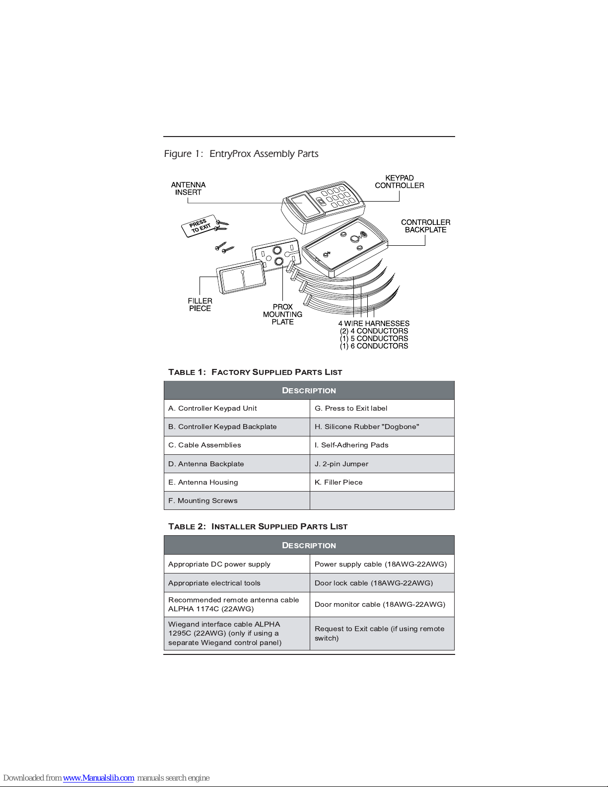
A. Controller Keypad Unit G. Press to Exit label
B. Controller Keypad Backplate H. Silicone Rubber "Dogbone"
C. Cable Assemblies I. Self-Adhering Pads
D. Antenna Backplate J. 2-pin Jumper
E. Antenna Housing K. Filler Piece
F. Mounting Screws
Figure 1: EntryProx Assembly Parts
T
ABLE
2: I
NSTALLERSUPPLIEDPARTSLIST
D
ESCRIPTION
Appropriate DC power supply Power supply cable (18AWG-22AWG)
Appropriate electrical tools Door lock cable (18AWG-22AWG)
Recommended remote antenna cable
ALPHA 1174C (22AWG)
Door monitor cable (18AWG-22AWG)
Wiegand interface cable ALPHA
1295C (22AWG) (only if using a
separate Wiegand control panel)
Request to Exit cable (if using remote
switch)
Page 7
EntyProx
™
Installation Introduction
iv
T
ABLE
3: S
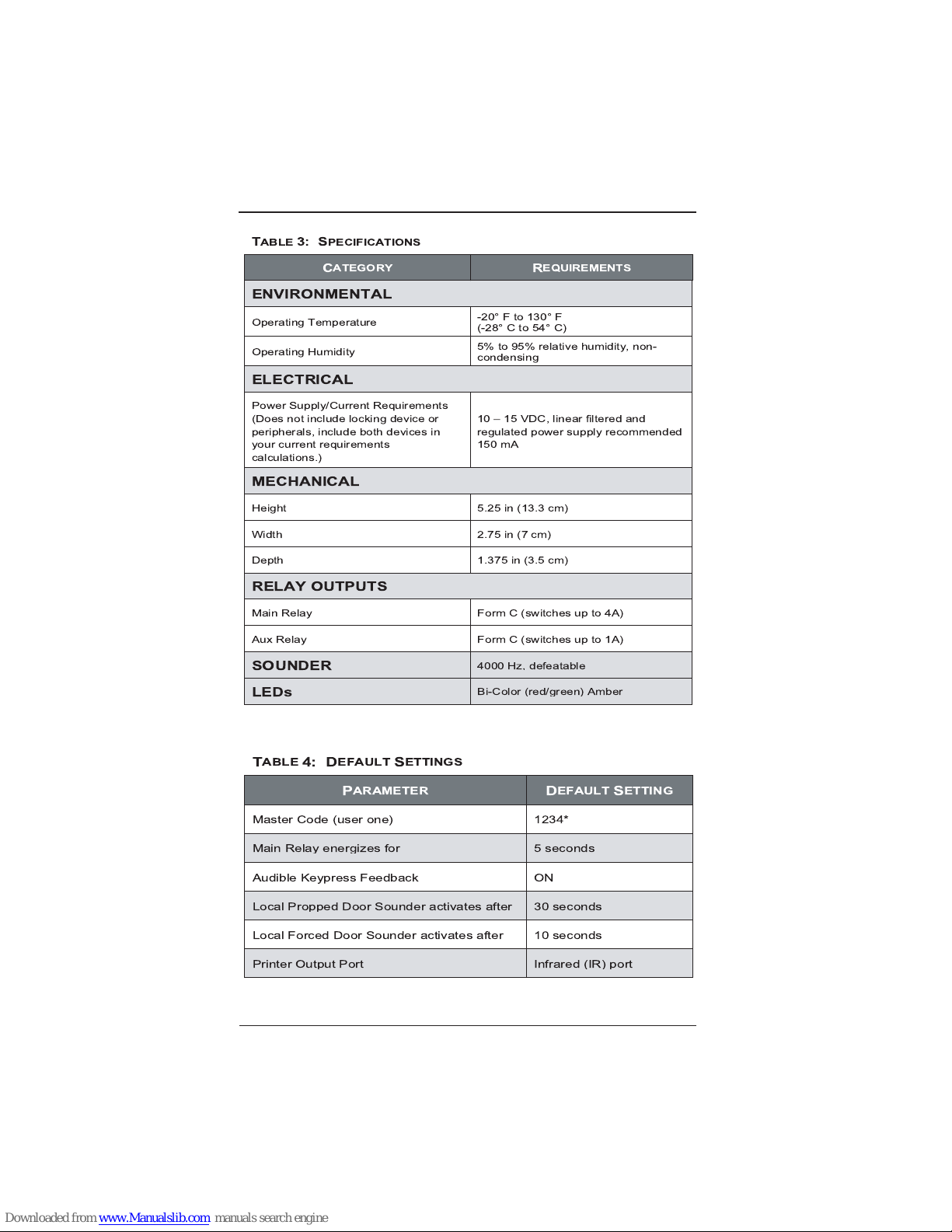
PECIFICATIONS
C
ATEGORY
R
EQUIREMENTS
ENVIRONMENTAL
Operating Temperature
-20°Fto130°F
(-28° C to 54° C)
Operating Humidity
5% to 95% relative humidity, non-
condensing
ELECTRICAL
Power Supply/Current Requirements
(Does not include locking device or
peripherals, include both devices in
your current requirements
calculations.)
10 15 VDC, linear filtered and
regulated power supply recommended
150 mA
MECHANICAL
Height 5.25 in (13.3 cm)
Width 2.75in(7cm)
Depth 1.375 in (3.5 cm)
RELAY OUTPUTS
Main Relay Form C (switches up to 4A)
AuxRelay FormC(switchesupto1A)
SOUNDER
4000 Hz, defeatable
LEDs
Bi-Color (red/green) Amber
T
ABLE
4: D
EFAULTSETTINGS
P
ARAMETER
D
EFAULTSETTING
Master Code (user one) 1234*
Main Relay energizes for 5 seconds
Audible Keypress Feedback ON
Local Propped Door Sounder activates after 30 seconds
Local Forced Door Sounder activates after 10 seconds
Printer Output Port Infrared (IR) port
Page 8

Installation Section 1 EntyProx
™
1-1
Section 1 - Installing the EntryProx
You can install the EntryProx unit by using a standard installation
method or a secure installation method. In a standard installation
the antenna housing remains intact with the controller keypad. A
standard installation involves:
• Mounting the EntryProx unit outside a secured area, such as
outside a main entrance.
• Wiring the EntryProx unit for door locks and alarm out-puts. In
a secure installation the antenna housing is removed from the
controller keypad and mounted outside a secured area. The
blank filler piece is then inserted into the controller keypad in
its place.
Note: If you enable the Request to Exit function, apply the "Press
to Exit" label to the filler piece. Refer to the "Wiring the Request to
Exit Switch" section for more information.
A secure installation involves:
• Mounting the EntryProx unit in a secured area, such as inside
a main reception area.
• Wiring the EntryProx unit for door locks and alarm out-puts.
• Mounting the Antenna Housing.
• Attaching the Press to Exit label (optional).
Note: If you use the secure installation method, you need to
mount and wire the antenna housing no more than 10-feet away
from the controller keypad unit.
Page 9
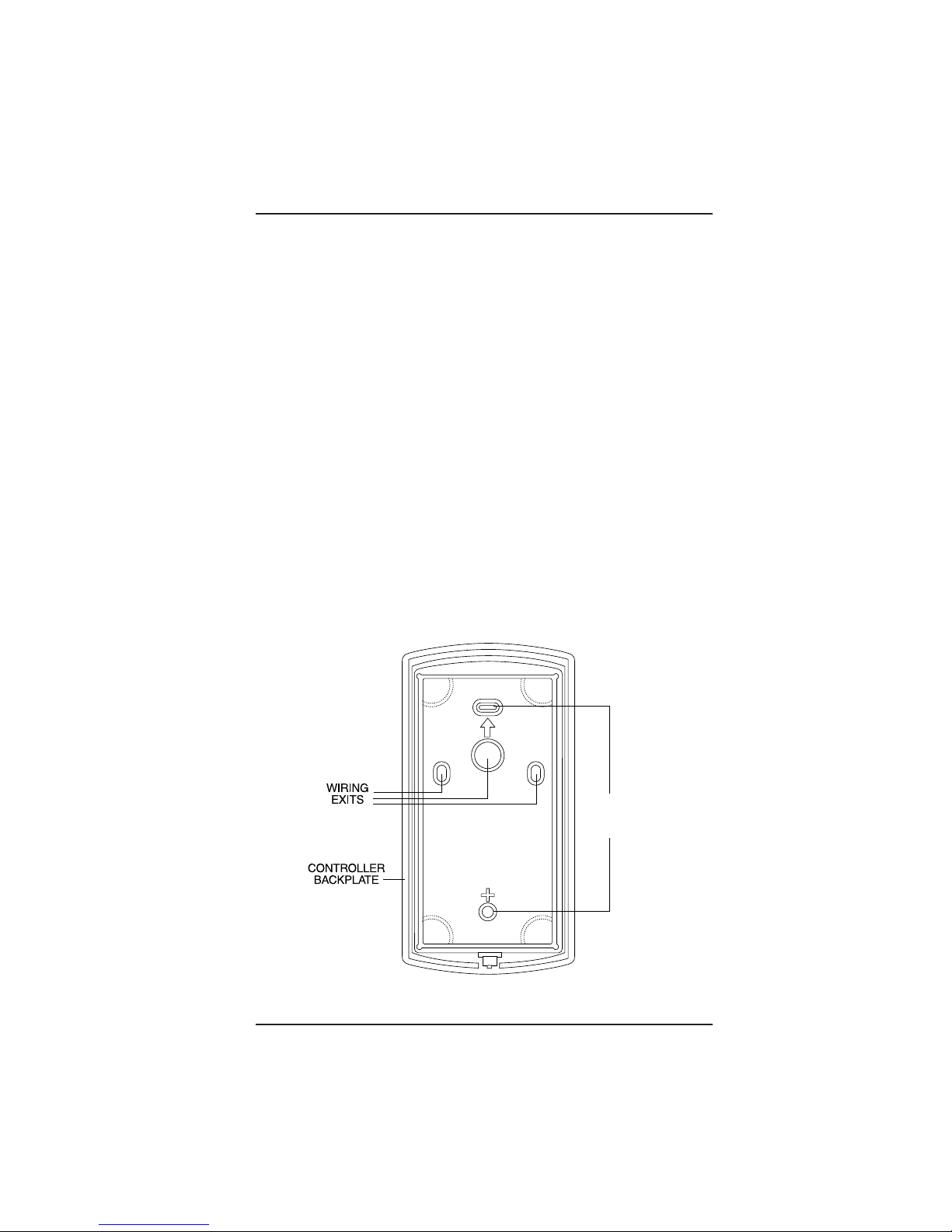
FIGURE 2: REMOVING THE WIRING EXITS AND MOUNTING HOLES
Installation Section 1 EntyProx
™
1-2
Mounting the EntryProx Unit
To mount the EntryProx unit to a wall surface, refer to Figure 2
and follow these instructions.
Instructions:
1. Remove the hex screw located at the bottom of the
EntryProx unit.
2. Disconnect the backplate of the EntryProx unit from the front
controller keypad.
3. Remove the wire exits and mounting hole cut-outs from the
backplate as shown in Figure 2.
Note: If you mount the EntryProx unit to a glass surface DO NOT
remove the wire exits on the backplate. Remove the appropriate
wire exit cut-outs located on each side of the controller keypad
case.
4. Attach the backplate to a wall or glass surface using the
mounting screws or the self-adhesive fasteners.
Mounting
Holes
Page 10
EntyProx
™
Installation Section 1
1-3
Wiring the Controller Keypad for a Standard Installation
To wire the EntryProx unit for a standard installation, refer to
Figures 3 and 4 and follow these instructions.
Instructions:
1. Touch a grounded object BEFORE touching the main circuit
board to guard against possible static discharges.
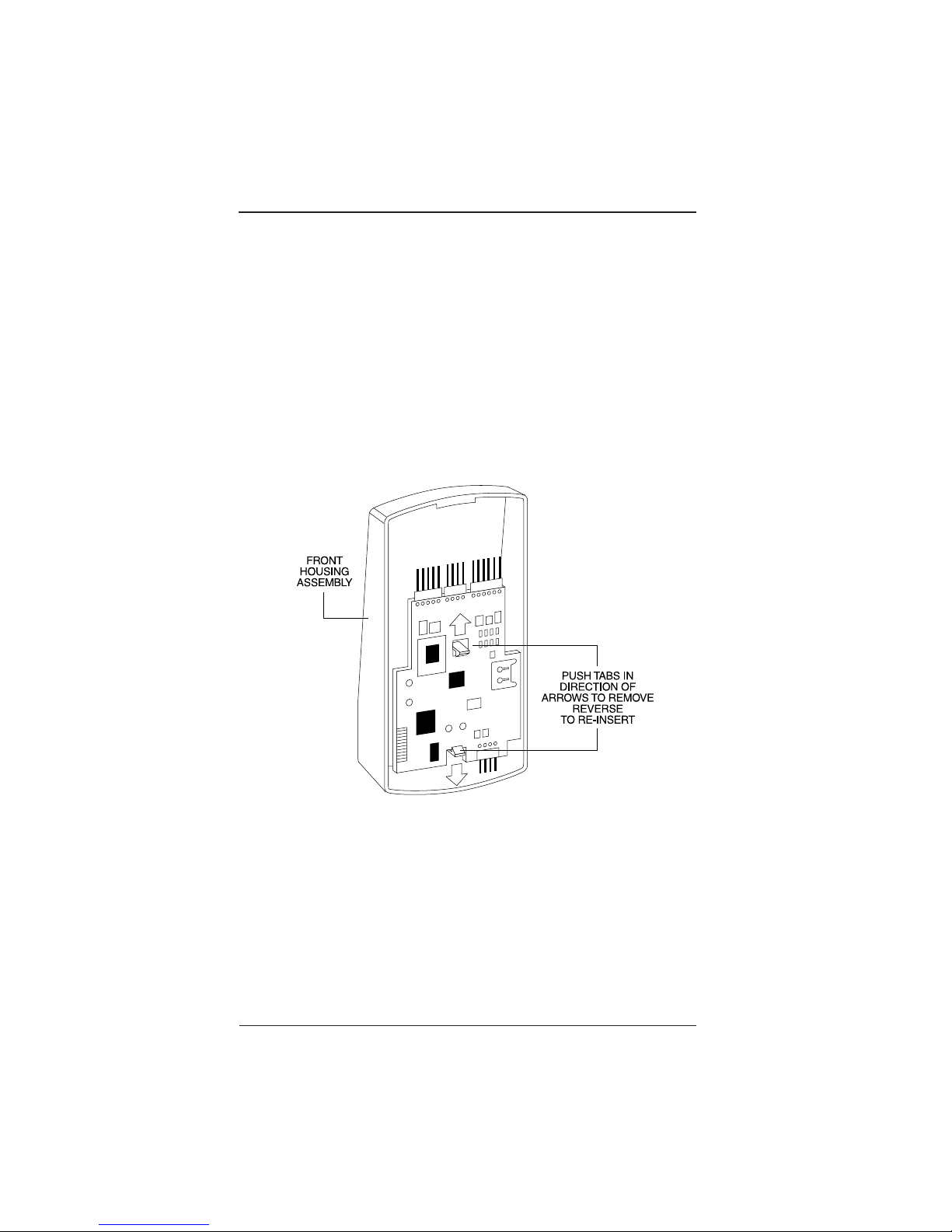
2. Remove the main circuit board by pushing outward on the
two spring tabs in the direction shown in Figure 3.
3. Lift the main circuit board.
Note: A ribbon cable holds the main circuit board to the controller
keypad board. DO NOT CUT OR REMOVE this cable from its
connector.
4. Make the wiring connections for the door locks and alarm
outputs. Refer to the “Wiring EntryProx” section for appropriate wiring diagrams.
FIGURE 3: REMOVING THE CIRCUIT BOARD
Page 11
Installation Section 1 EntyProx
™
1-4
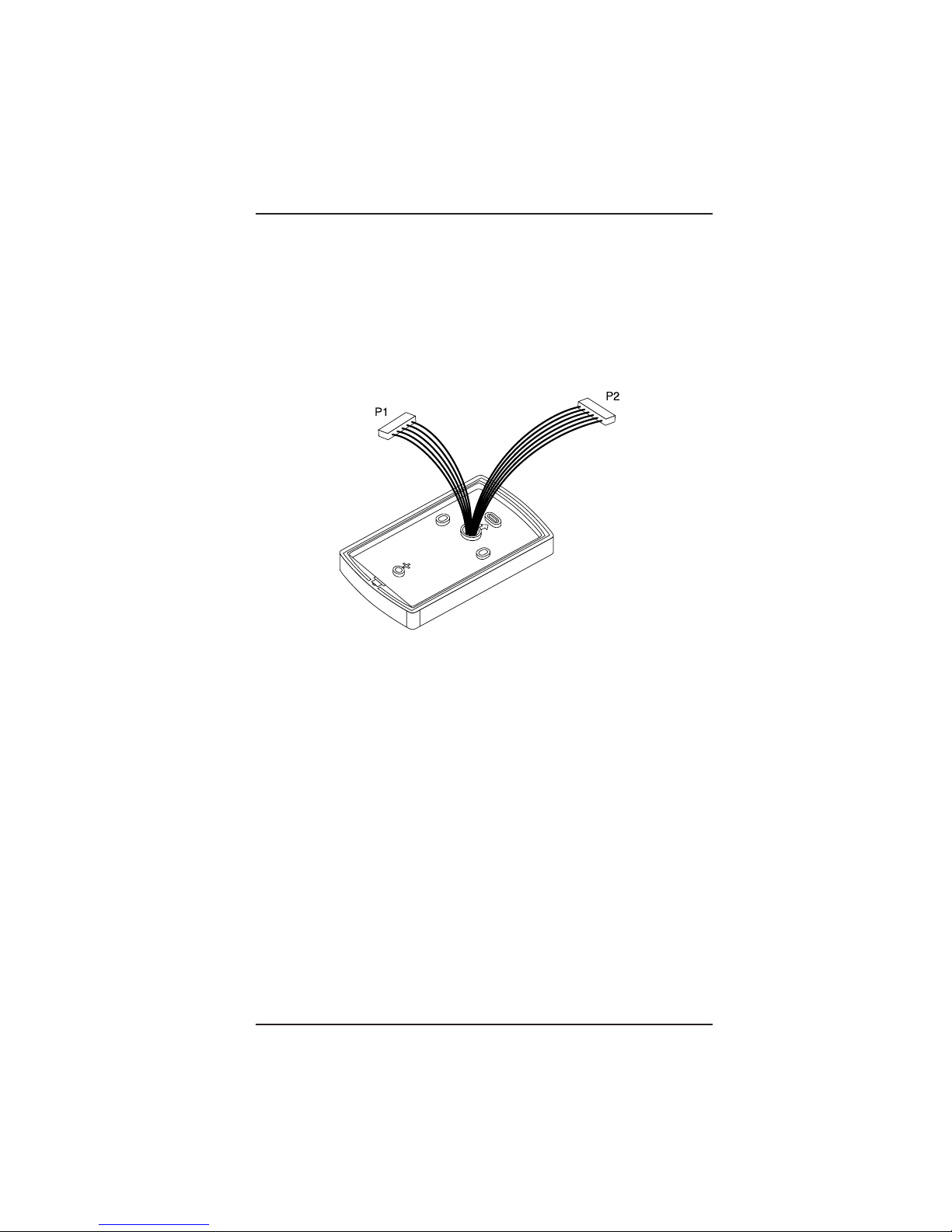
5. Pull the wires through the backplate as shown in Figure 4.
6. Reattach the main circuit board to the controller keypad unit.
7. Attach the controller keypad unit to the mounted backplate
and secure the EntryProx unit with a hex screw or tamper
screw.
FIGURE 4: PULLING THE WIRES THROUGH THE BACKPLATE
Page 12
EntyProx
™
Installation Section 1
1-5
Wiring the Controller Keypad for a Secure Installation
In a secure installation, the antenna housing is removed from the
controller keypad and is located no more than 10 feet away from
the EntryProx unit. To wire the EntryProx unit for a secure installation, refer to Figures 5 and 6 and follow these instructions.
Instructions:
1. Touch a grounded object BEFORE touching the main circuit
board to guard against possible static discharges.
2. Remove the main circuit board by pushing outward on the
two spring tabs in the direction shown in Figure 3.
3. Lift the main circuit board.
Note: A ribbon cable holds the main circuit board to the controller
keypad board. DO NOT CUT OR REMOVE this cable from its
connector.
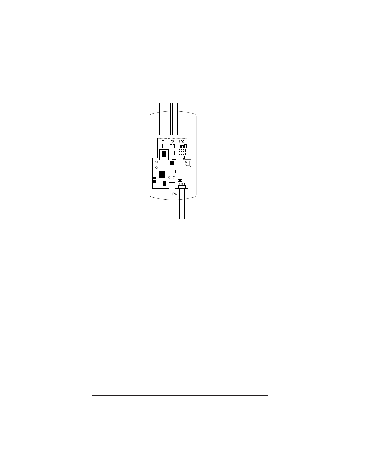
4. Unplug the four-pin connector P4 from the main circuit
board. See Figure 5.
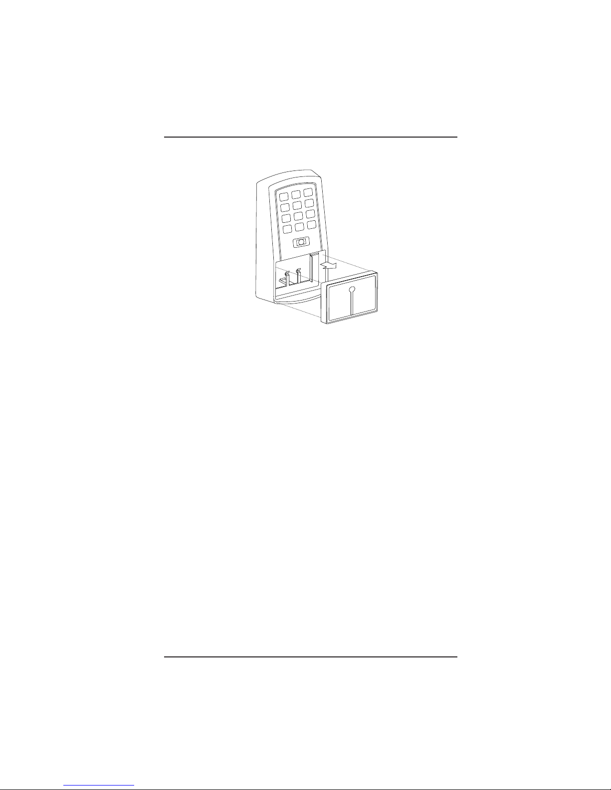
5. Release the antenna housing from the controller keypad by
pressing inward on the four securing tabs.
6. Remove the antenna housing from the controller keypad by
pushing forward as shown in Figure 6.
P4 Connector
Cable Assembly
FIGURE 5: REMOVING THE P4 CONNECTOR
Page 13
Installation Section 1 EntyProx
™
1-6
7. Insert the extra 10-inch antenna cable assembly into con-
nector P4.
8. Splice in additional antenna cable Alpha 1174C (22AWG) up
to a maximum of 10 feet.
Note: The Alpha 1174C antenna cable is not supplied with the
EntryProx unit.
9. Pull the additional antenna cable through the mounted back-
plate as shown in Figure 4.
10. Make the wiring connections for the Request to Exit switch,
the door locks, and the alarm outputs. Refer to the “Wiring
EntryProx” section for appropriate wiring diagrams.
11. Reattach the main circuit board to the controller keypad
unit.
12. Attach the controller keypad unit to the mounted backplate
and secure the EntryProx unit with a hex screw or tamper
screw.
13. Run the additional antenna cable to the antenna housing
location.
14. Mount and wire the antenna housing.
FIGURE 6: REMOVING THE ANTENNA HOUSING
Page 14
EntyProx
™
Installation Section 1
1-7
Mounting and Wiring the Antenna Housing for a Secure
Installation
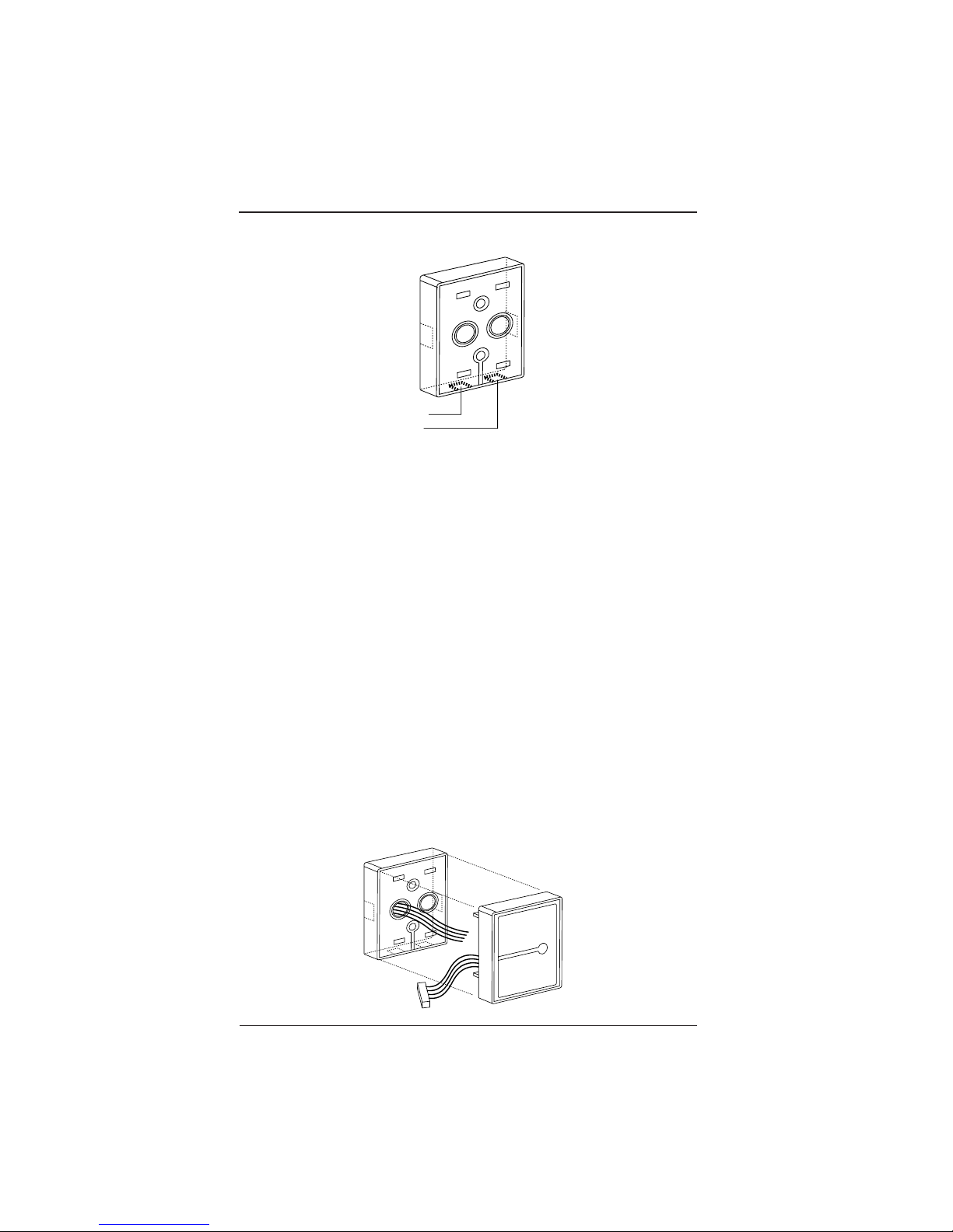
To mount and wire the antenna housing, refer to Figures 7 and 8
and follow these instructions.
Instructions:
1. Position and secure the antenna backplate to the mounting
surface so that the two moisture release holes are on the
bottom.
2. Pull the antenna cable assembly through the backplate’s
cable holes.
3. Attach the antenna housing to the backplate by inserting the
four securing tabs into the backplate.
4. Cut the plastic connector off the antenna cable assembly.
5. Splice in the additional antenna cable. Be careful to match
the wire colors to the proper pin connectors on the 10-inch
antenna cable assembly.
6. Seal the wire holes with silicone.
FIGURE 8: ATTACHING THE ANTENNA HOUSING
Moisture
Release
Holes
FIGURE 7: MOUNTING THE ANTENNA BACKPLATE
Page 15
Installation Section 1 EntyProx
™
1-8
Selecting a Filler or Request to Exit Operation
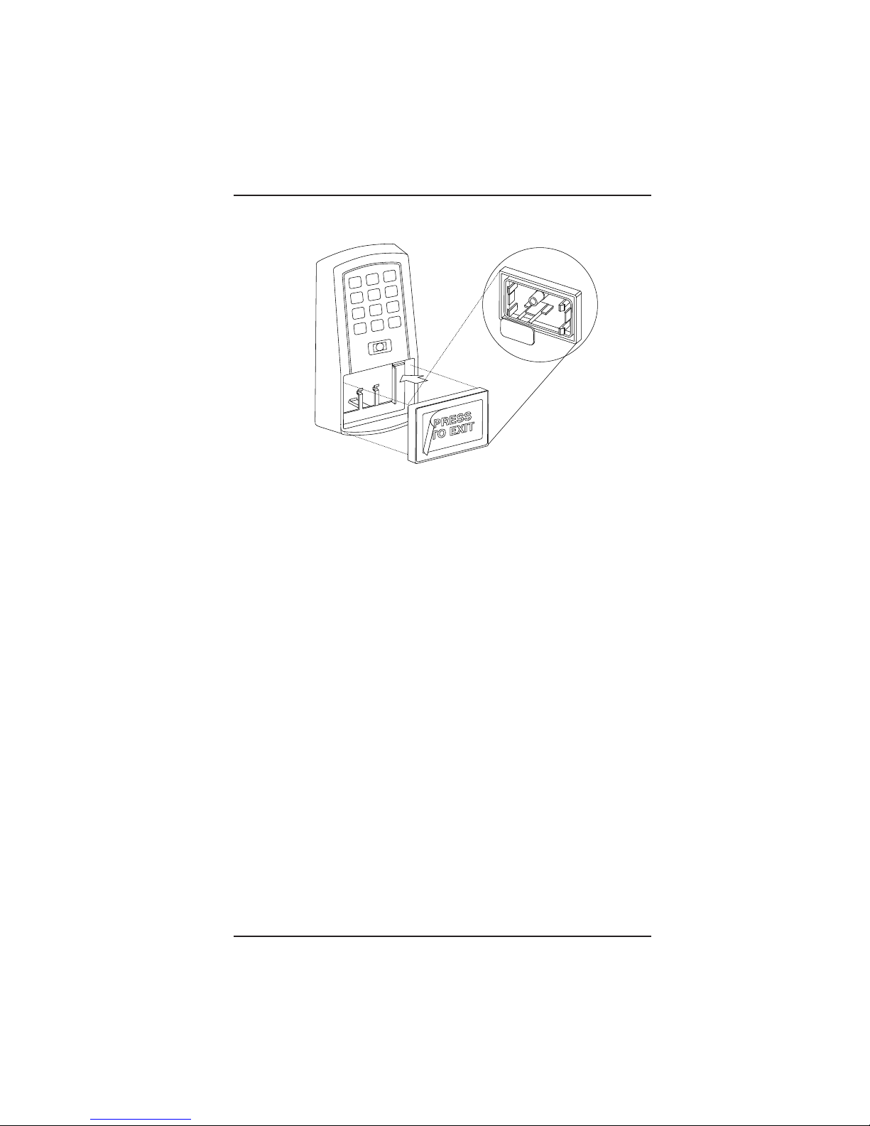
The filler piece replaces the antenna housing on the controller keypad when you use the secure installation. If you are not going to
use the filler piece as a Request to Exit switch:
• Insert the filler piece into the opening on the controller key
pad.
• Apply the blank label.
If you are going to use the filler piece as a Request to Exit switch:
• Remove the two plastic side tabs on the filler piece.
• Apply the “Press to Exit” label to the filler piece.
• Insert the silicone rubber “dogbone” over the two aligned pins
on the switch activator.
• Insert the filler piece into the opening on the controller key
pad.
• Set the internal request to exit switch to ON. Refer to Table 6:
Program Commands, Programming Code 30, Option 7
Wiegand
Note: Refer to the “Wiring the Request to Exit Switch” section for
the appropriate wiring diagrams.
FIGURE 9: USING THE FILLER PIECE AS A REQUEST TO EXIT SWITCH
Page 16
Wiring the EntryProx - Section 2 EntyProx
™
2-1
Section 2 - Wiring the EntryProx
This section includes three wiring diagrams:
• Wiring the main relay
• Wiring the auxiliary relay
• Wiring the Request to Exit switch
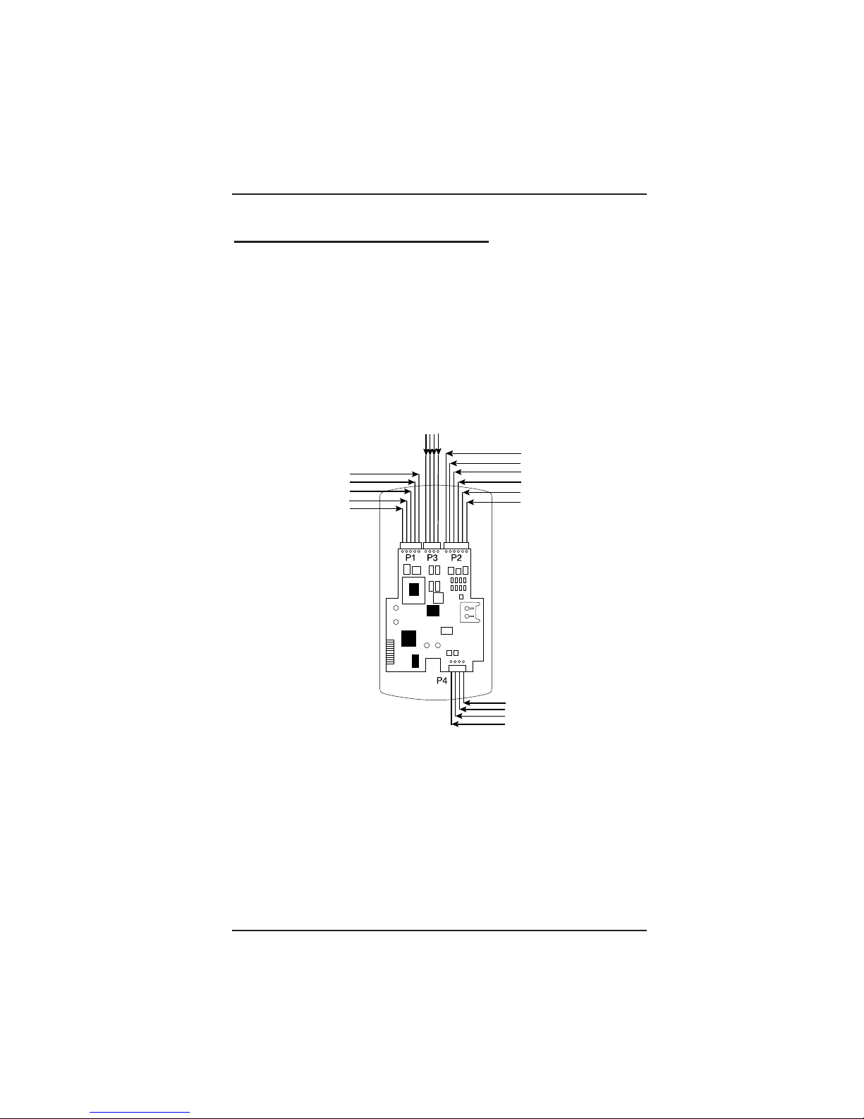
Figure 10 illustrates the location of the four pin connectors on the
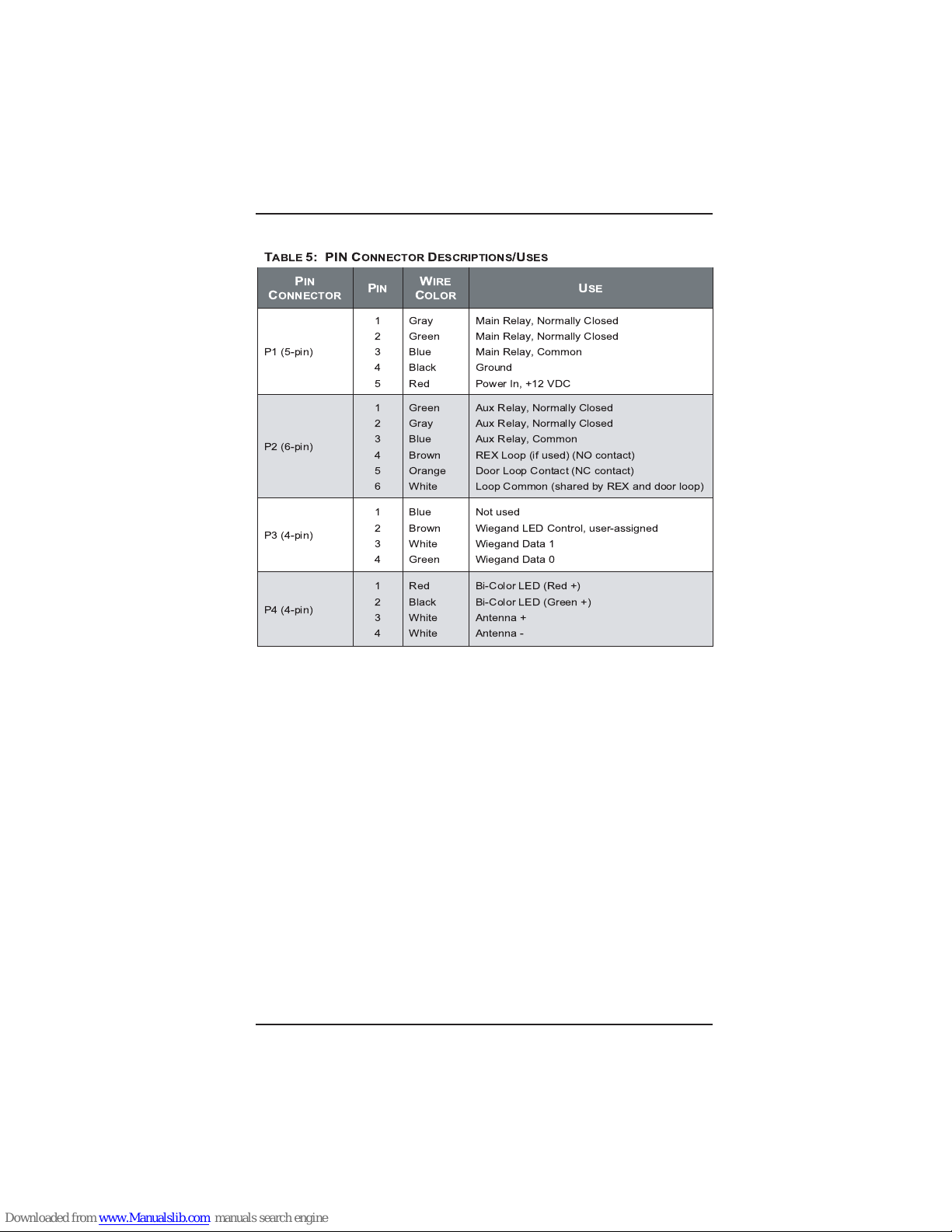
main circuit board. Table 5 on Page 2-2 describes each pin and
its use.
1
2
3
4
5
6
1
2
3
4
5
1 2 3 4
1
2
3
4
FIGURE 10: PIN LOCATOR DIAGRAM
Page 17
Wiring the EntryProx - Section 2 EntyProx
™
2-2
T
ABLE
5: PIN C
ONNECTORDESCRIPTIONS/USES
P
IN
C
ONNECTOR
P
IN
W
IRE
C
OLOR
U
SE
P1 (5-pin)
1
2
3
4
5
Gray
Green
Blue
Black
Red
Main Relay, Normally Closed
Main Relay, Normally Closed
Main Relay, Common
Ground
Power In, +12 VDC
P2 (6-pin)
1
2
3
4
5
6
Green
Gray
Blue
Brown
Orange
White
Aux Relay, Normally Closed
Aux Relay, Normally Closed
Aux Relay, Common
REX Loop (if used) (NO contact)
Door Loop Contact (NC contact)
Loop Common (shared by REX and door loop)
P3 (4-pin)
1
2
3
4
Blue
Brown
White
Green
Not used
Wiegand LED Control, user-assigned
Wiegand Data 1
Wiegand Data 0
P4 (4-pin)
1
2
3
4
Red
Black
White
White
Bi-Color LED (Red +)
Bi-Color LED (Green +)
Antenna +
Antenna -
Page 18
EntyProx
™
Wiring the EntryProx - Section 2
2-3
WIRING THE MAIN RELAY
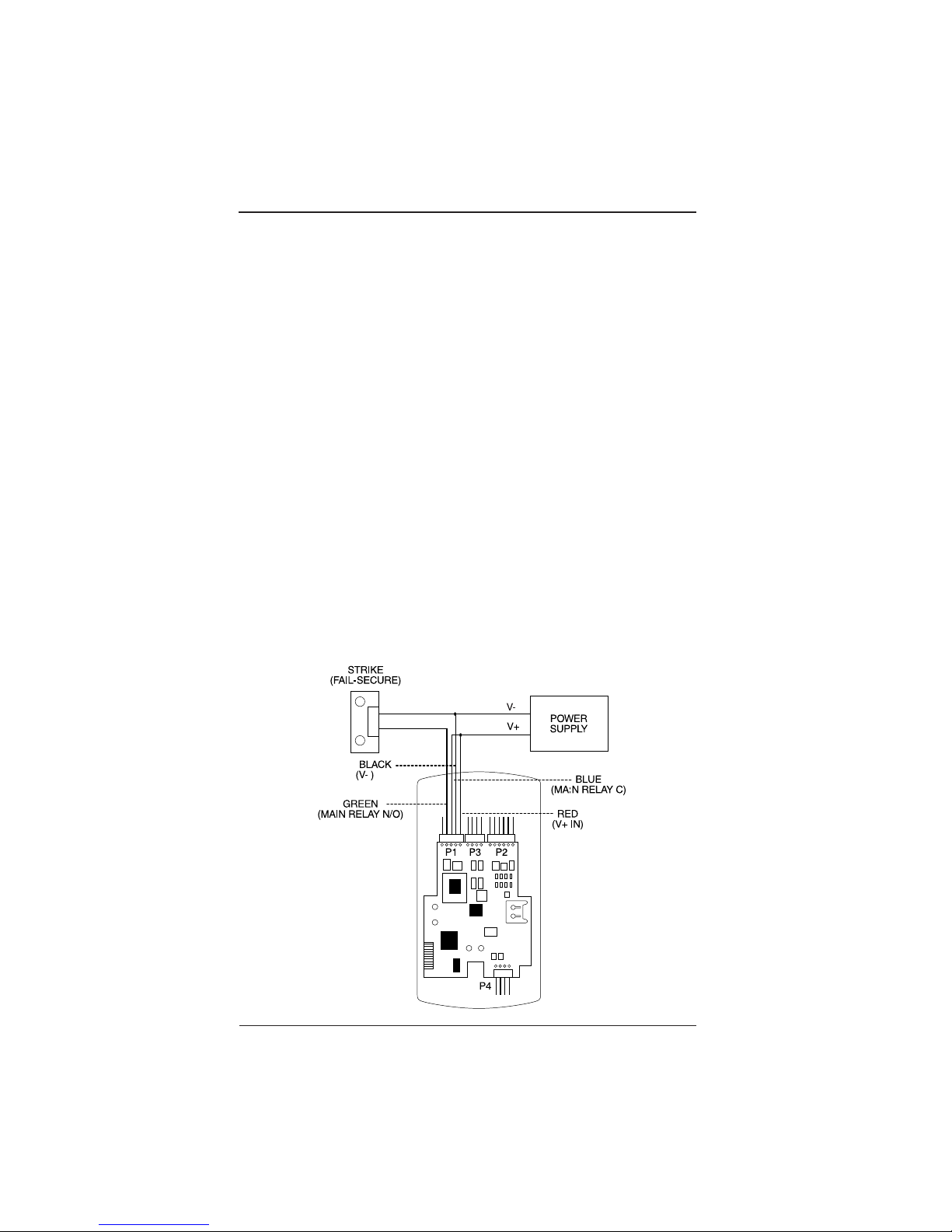
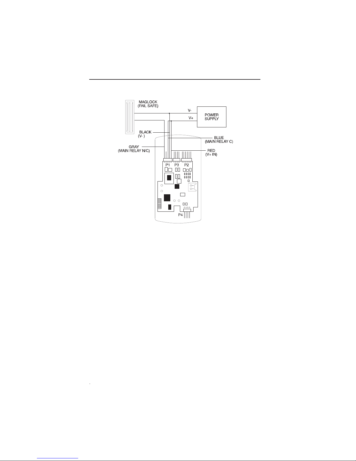
The main relay for the door locking device is wired to connector
P1 on the EntryProx main circuit board. To wire the EntryProx unit
to the door locking device, refer to Figures 11 and 12 and follow
these instructions.
Instructions:
1. Power off the EntryProx unit and remove the controller key
pad from the backplate (if not already removed).
2. Remove the main circuit board from the controller keypad
as shown in Figure 3.
3. Locate connector P1 on the main circuit board.
4. Refer to Figure 11 to make the wiring connections for a Fail-
Secure Strike or Lock.
5. Refer to Figure 12 to make the wiring connections for a
Maglock or Fail-Safe Strike.
FIGURE 11: ELECTRIC STRIKE (FAIL SECURE WIRING DIAGRAM)
Page 19

Wiring the EntryProx - Section 2 EntyProx
™
2-4
6. Reattach the main circuit board to the controller keypad.
7. Reattach the controller keypad to the backplate and secure
the EntryProx unit with a hex screw or tamper screw.
Note: You can make the wiring connections for a gate actuator
(diagram not shown) by connecting the Blue (C) wire and the
Green (N/O) wire directly to the input. DO NOT connect a power
supply to the relay.
Page 20
EntyProx
™
Wiring the EntryProx - Section 2
2-5
WIRING THE AUXILIARY RELAY
The EntryProx unit has an auxiliary relay feature that allows for
customized alarm programming. Pins 1, 2, and 3 on the P2
connector can be wired for one of the following alarm outputs:
• Alarm shunt
• Forced or propped door
The alarm shunt operation allows you to use the auxiliary relay to
bypass a door contact that is monitored by a separate alarm
system. If the entry or exit is controlled by the EntryProx unit, an
intrusion alarm will not be generated if the door is opened using an
access card or PIN number. The forced or propped door operation
allows you to use the auxiliary relay to install a local warning, such
as an audible or visual indicator if:
• A door is opened without using an access card or PIN
number at the EntryProx unit.
• A door is legitimately opened but is held open too long.
Note: The auxiliary relay audible and visual indicators and the
door open times can be programmed. Refer to Table 6: Program
Commands for more information.
FIGURE 12: MAGLOCK (FAIL SAFE WIRING DIAGRAM)
Page 21
Wiring the EntryProx - Section 2 EntyProx
™
2-6
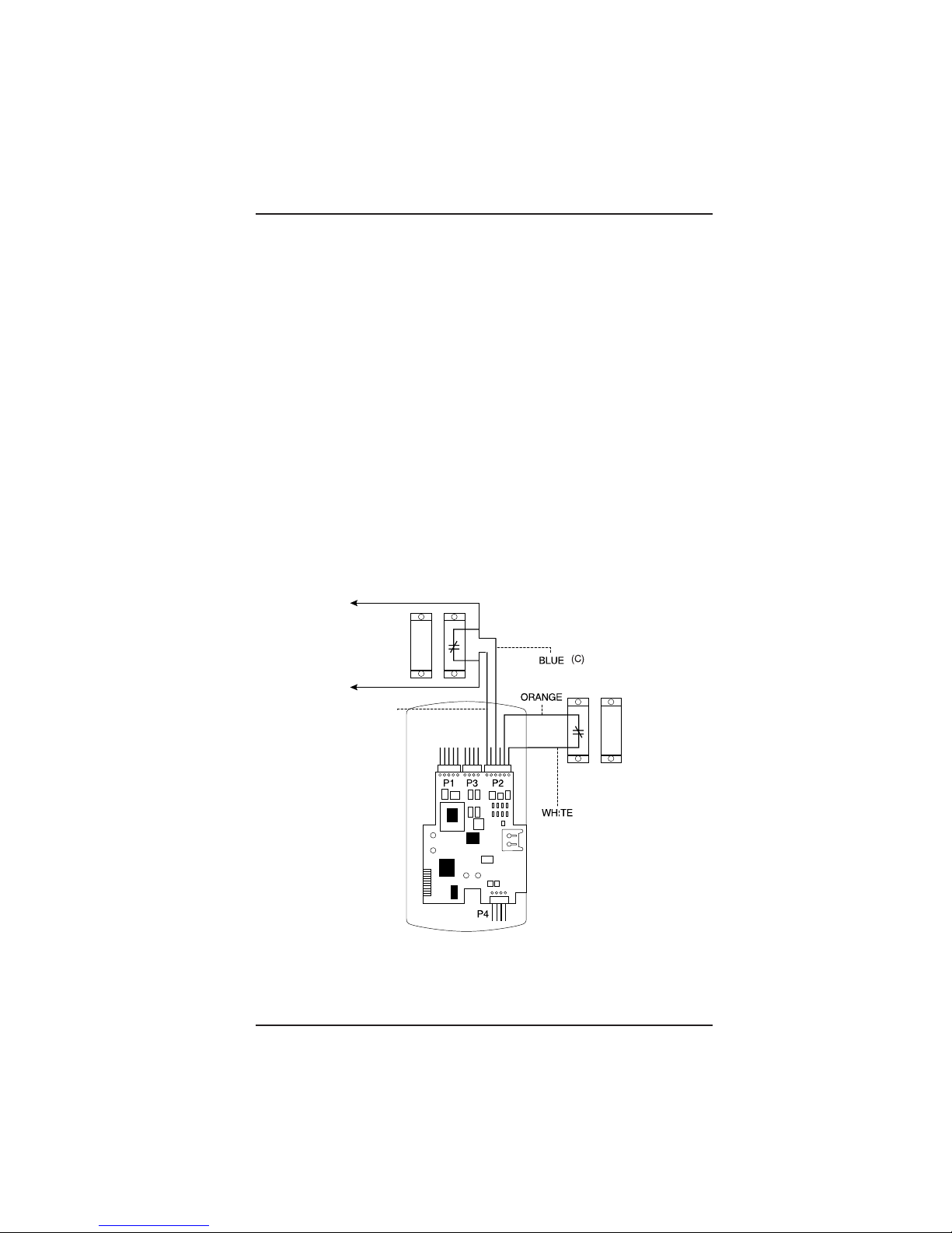
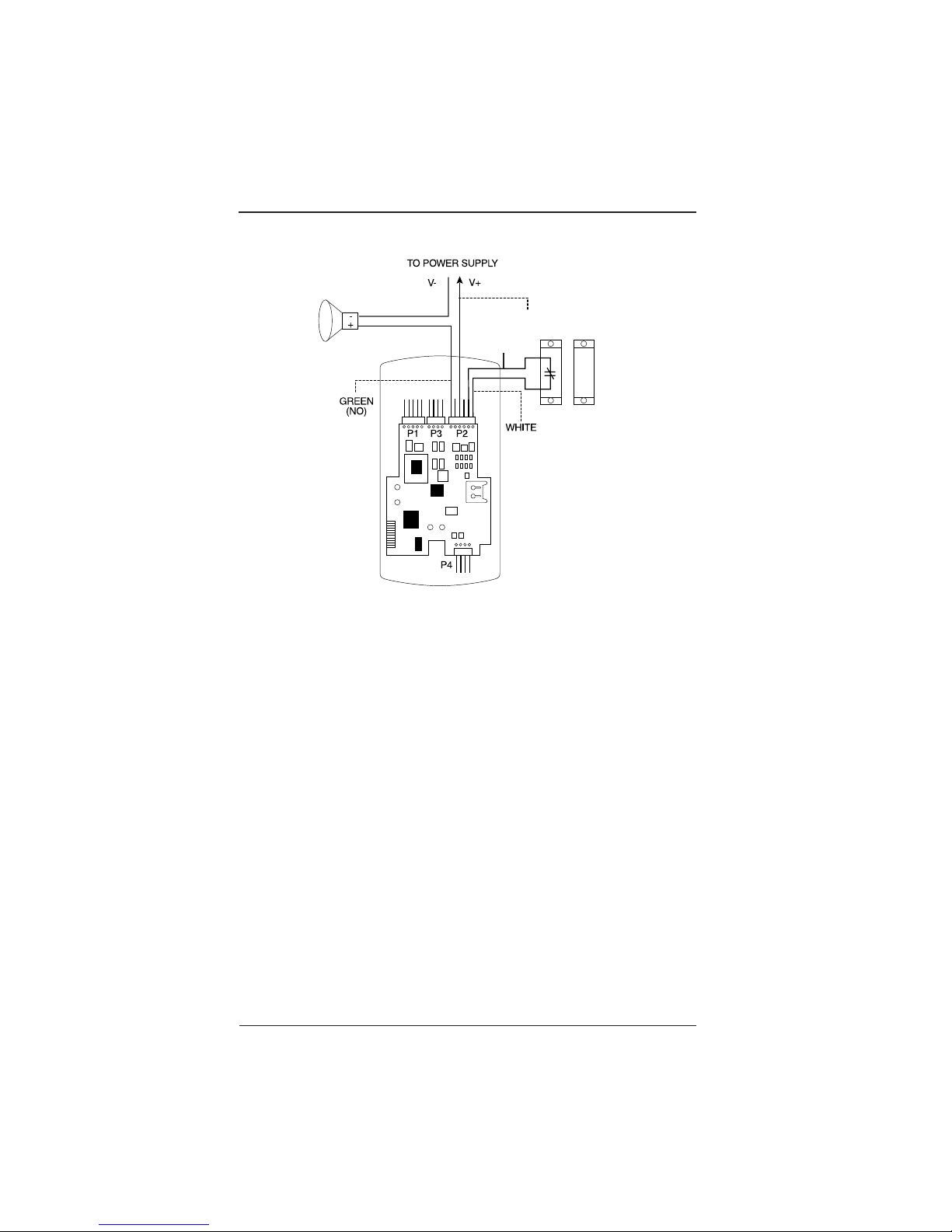
To wire the auxiliary relay, refer to Figures 13 and 14 and follow
these instructions.
Instructions:
1. Power off the EntryProx unit and remove the controller key
pad from the backplate (if not already removed).
2. Remove the main circuit board from the controller keypad as
shown in Figure 3.
3. Locate connector P2 on the main circuit board.
4. Refer to Figure 13 to make the wiring connections for the
alarm shunt operation.
5. Refer to Figure 14 to make the wiring connections for the
forced or propped door operation.
6. Reattach the main circuit board to the controller keypad.
7. Reattach the controller keypad to the backplate and secure
the EntryProx unit with a hex screw or tamper screw.
Door Contact
(Monitored by
Alarm Panel)
Green
(N/O)
Door Contact
(Monitored by
EntryProx Unit)
FIGURE 13: WIRING AUX RELAY FOR ALARM SHUNT OPERATION
Page 22
EntyProx
™
Wiring the EntryProx - Section 2
2-7
ORANGE
BLUE (C)
Door Contact
(Monitored by
EntryProx unit)
FIGURE 14: WIRING AUX RELAY FOR PROPPED/FORCED DOOR ALARM
Page 23

Wiring the EntryProx - Section 2 EntyProx
™
2-8
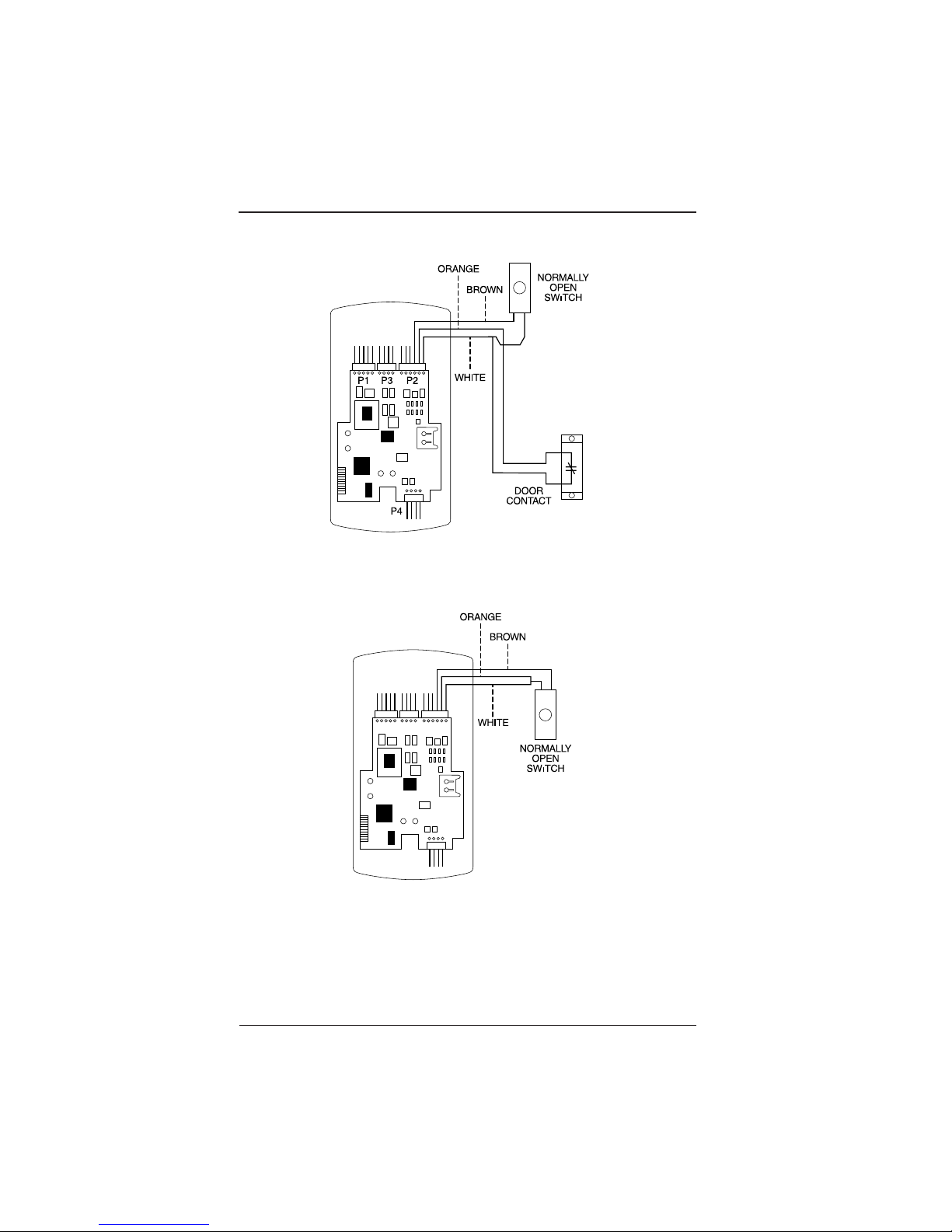
WIRING THE REQUEST TO EXIT SWITCH
The EntryProx Request to Exit switch is a momentary input that
engages the main relay and is intended for use with secure installations. If the alarm shunt relay is enabled, the Request to Exit
switch is activated to prevent false alarms. The Transaction Log
records all Request to Exit usages for monitoring purposes. To
wire the EntryProx unit for the Request to Exit switch, refer to
Figures 15 and 16 and follow these instructions.
Instructions:
1. Power off the EntryProx unit and remove the controller
keypad from the backplate (if not already removed).
2. Remove the main circuit board from the controller keypad
as shown in Figure 3.
3. Locate connector P2 on the main circuit board.
4. Refer to Figure 15 to make the wiring connections for using
a door contact.
5. Refer to Figure 16 to make the wiring connections for NOT
using a door contact.
Note: If you do not use a door contact, you need to twist the white
and orange wires together or the REX input will not function.
6. Reattach the main circuit board to the controller keypad.
7. Reattach the controller keypad to the backplate and secure
the EntryProx unit with a hex screw or tamper screw.
Note: The door contact must be closed for the Request to Exit
feature to work properly.
Page 24
EntyProx
™
Wiring the EntryProx - Section 2
2-9
FIGURE 16: WIRING REQUEST TO EXIT SWITCH (NO DOOR CONTACT)
FIGURE 15: WIRING REQUEST TO EXIT SWITCH (WITH DOOR CONTACT)
Page 25

Wiring the EntryProx - Section 2 EntyProx
™
2-10
Page 26

Programming the EntryProx - Section 3 EntyProx
™
3-1
Section 3 - Programming the EntryProx
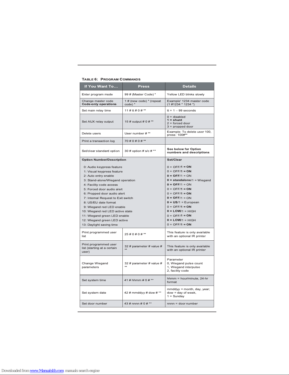
Table 6 describes the programming commands available with the
EntryProx unit and explains how to execute them. For more information on programming options, you can download the
Installation/Programming Manual from HID’s web site
(www.HIDCorp.com), or contact your local distributor. If you want
to program the EntryProx unit to operate with a separate Wiegand
central access panel, the following features are not accessible:
• The EntryProx unit does not control door lock or unlocking
operations.
• The EntryProx unit is not able to store codes in memory.
• The main and auxiliary relay functions are turned off.
For more information on programming the EntryProx unit for
Wiegand operations, please contact your local distributor.
Note: Defaults are in bold. References in parenthesis are in the
Installation/Programming.
Page 27
Programming the EntryProx - Section 3 EntyProx
™
3-2
T
ABLE
6: P
ROGRAMCOMMANDS
If You Want To Press Details
Enter program mode 99 # (Master Code) * Yellow LED blinks slowly
Change master code
Code-only operations
1 # (new code) * (repeat
code) *
Example' 1234 master code
(1 #1234 * 1234 *)
Set main relay time 11 # tt # 0 # ** tt = 1 99 seconds
Set AUX relay output 15 # output # 0 # **
0=disabled
1 = shunt
2 = forced door
3 = propped door
Delete users User number # **
Example: To delete user 100,
press: 100#**
Print a transaction log 70#0#0#**
Set/clear standard option 30 # option # s/c # **
See below for Option
numbers and descriptions
Option Number/Description
0: Audio keypress feature
1: Visual keypress feature
2: Auto entry enable
3: Stand-alone/Wiegand operation
4: Facility code access
5: Forced door audio alert
6: Propped door audio alert
7: Internal Request to Exit switch
8: US/EU date format
9: Wiegand red LED enable
10: Wiegand red LED active state
11: Wiegand green LED enable
12: Wiegand green LED active
13: Daylight saving time
Set/Clear
0=OFF/
1=ON
0=OFF/
1=ON
0=OFF
/1=ON
0 = standalone
/1=Wiegand
0=OFF
/1=ON
0=OFF/
1=ON
0=OFF/
1=ON
0=OFF
/1=ON
0=US
/1 = European
0=OFF/
1=ON
0=LOW
/1 = HIGH
0=OFF/
1=ON
0=LOW
/1 = HIGH
0=OFF/
1=ON
Print programmed user
list
25#0#0#**
This feature is only available
with an optional IR printer
Print programmed user
list (starting at a certain
user)
32 # parameter # value #**This feature is only available
with an optional IR printer
Change Wiegand
parameters
32 # parameter # value #
**
Parameter
0, Wiegand pulse count
1, Wiegand interpulse
2, facility code
Set system time 41 # hhmm # 0 # **
hhmm = hour/minute, 24-hr
format
Set system date 42 # mmddyy # dow # **
mmddyy = month, day, year;
dow = day of week,
1 = Sunday
Set door number 43 # nnnn # 0 # ** nnnn = door number
Page 28
Set propped door time
(this sets time for both
the Aux Relay and local
sounder)
44#ttt#0#**
ttt = propped door time, to
nearest 10's seconds,
entered as 10 990;
default = 30 seconds
Set forced door time (this
sets time for both the Aux
Relay and local sounder)
45#ttt#0#**
ttt = forced door time, to
nearest 10's seconds,
entered as 10 990; default =
10 seconds
Delete memory
except
user list
and restore
system defaults (also see
command 46)
40 # 00000 # 00000 # **
Delete
all
memory and
reset system defaults
46 # 00000 # 00000 # **
Program user: Code
ONLY
Note: You can program the four
types of users shown to the right
50 # user-type # user
location # code * repeat
code *
0 Toggle/latch strike,
1 Normal Access,
2 Log Dump, and
3 Lockout
Program user:
Code AND Card
50 # user-type # user
location # * repeat code *
<present card>
Program user:
Card ONLY
50 # user-type # user
location # * * <present
card>
Program card user
manually:
Card ONLY
(26-bit cards ONLY)
51 # user-type # user
location # card ID * card
ID *
The card ID appears on the
card (facility code must be
entered first; see 32 # 2 #
command)
Program user:
Code OR Card
52 # user-type # user
location # code * repeat
code * <present card>
Perform batch entry of
users:
Card ONLY
(26-
bit cards ONLY)
56 # total count # start
card#cardID*cardID*
The card ID appears on the
card; (facility code must be
enteredfirst;see32#2#
command)
Print Transaction Log via
IR port
70# 0# 0# **
Set transaction log mask
(set/clear event logging):
set = 1, clear = 2
73 # event #set/clear # **
See below
EntyProx
™
Programming the EntryProx - Section 3
3-3
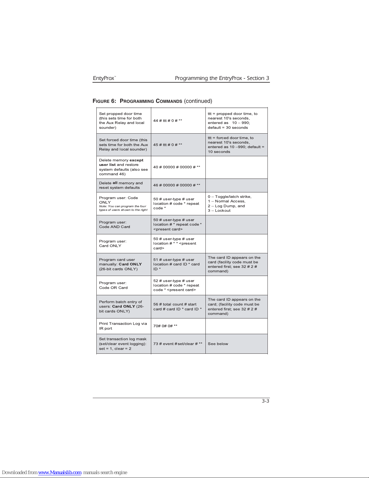
FIGURE 6: PROGRAMMING
COMMANDS
(continued)
Page 29
Programming the EntryProx - Section 3 EntyProx
™
3-4
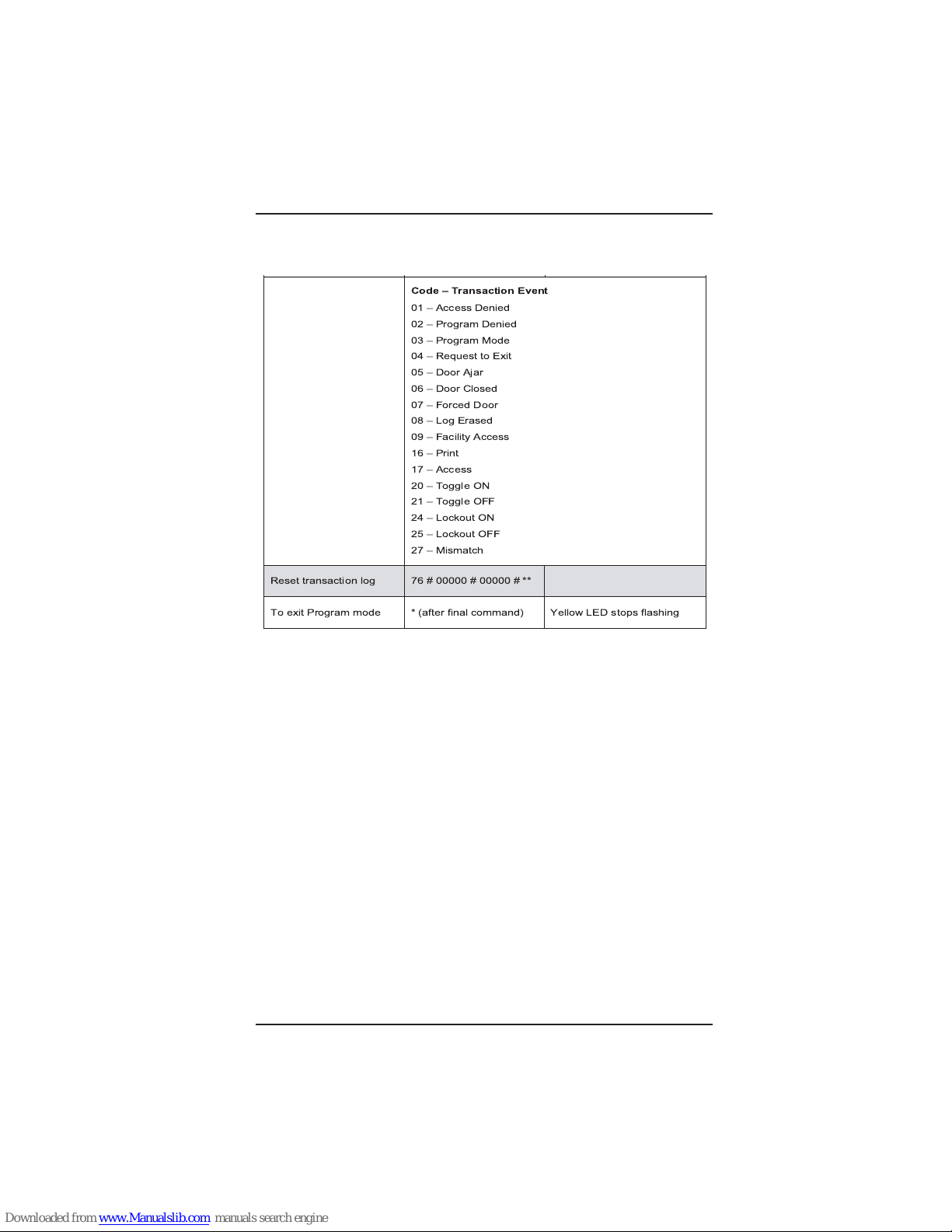
FIGURE 6: PROGRAMMING C
OMMANDS
(continued)
Code Transaction Event
01 Access Denied
02 Program Denied
03 Program Mode
04 Request to Exit
05 Door Ajar
06 Door Closed
07 Forced Door
08 Log Erased
09 Facility Access
16Print
17 Access
20 Toggle ON
21 Toggle OFF
24 Lockout ON
25 Lockout OFF
27 Mismatch
Reset transaction log 76 # 00000 # 00000 # **
To exit Program mode * (after final command) Yellow LED stops flashing
Page 30
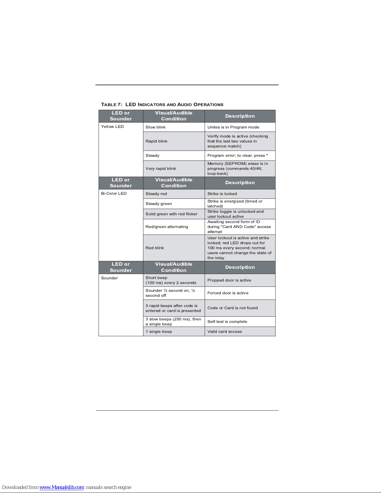
EntyProx
™
Programming the EntryProx - Section 3
3-5
T
ABLE
7: LED I
NDICATORS ANDAUDIOOPERATIONS
LED or
Sounder
Visual/Audible
Condition
Description
Slow blink Unites is in Program mode
Rapid blink
Verify mode is active (checking
that the last two values in
sequence match)
Steady Program error; to clear, press *
Yellow LED
Very rapid blink
Memory (EEPROM) erase is in
progress (commands 40/46,
loop-back)
LED or
Sounder
Visual/Audible
Condition
Description
Steady red Strike is locked
Steady green
Strike is energized (timed or
latched)
Solid green with red flicker
Strike toggle is unlocked and
user lockout active
Red/green alternating
Awaiting second form of ID
during "Card AND Code" access
attempt
Bi-Color LED
Red blink
User lockout is active and strike
locked; red LED drops out for
100 ms every second; normal
users cannot change the state of
the relay
LED or
Sounder
Visual/Audible
Condition
Description
Short beep
(100 ms) every 2 seconds
Propped door is active
Sounder ½ second on, ½
second off
Forced door is active
3 rapid beeps after code is
entered or card is presented
Code or Card is not found
3 slow beeps (250 ms), then
a single beep
Self-test is complete
Sounder
1 single beep Valid card access
Page 31

Programming the EntryProx - Section 3 EntyProx
™
3-6
PROGRAMMING HINTS
Wiegand Programming:
• If you are using 26-bit cards with one common facility code,
enter that code under Programming Code 32, parameter 2,
facility code, to allow batch programming or facility code only
operation.
• Review Programming Code 30, Options 0-13 to check if any
changes are needed.
User Card/PIN Code Programming:
• DO NOT program an access card or PIN code into User #1.
This is reserved for the Master Password only.
• Keep a written record of access cards and PIN codes. See
the example “Users Chart” located at the back of the manual.
• When using a PIN code to open a controlled door or gate,
always follow with the asterick (*) key.
• When using a PIN code and an access card, the code may be
entered before or after presenting the access card to the
reader. The LED flashes alternate red/green until both IDs are
presented.
Page 32

Page 33

5007 South Howell Avenue • Milwaukee, WI 53207 • (800)323-4576
www.nciaccess.com
 Loading...