

Page 1
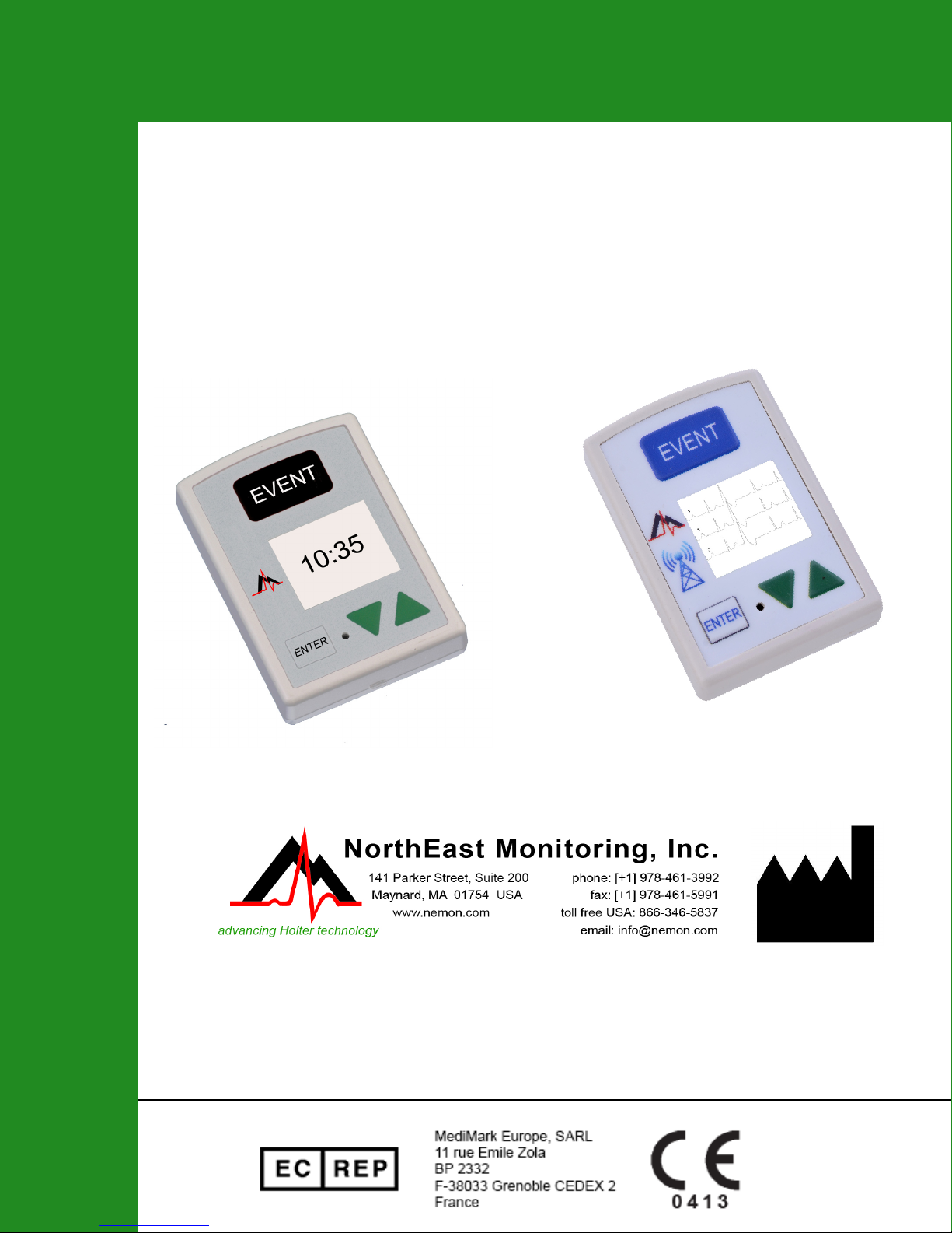
DR200/HE and DR300
Digital Holter/Event Recorder
Operator’s Manual
Part number:NEMM019-Rev-O
Last updated: September 2018
Copyright 2006-2018
All rights reserved
Page 2

DR200/HE & DR300 Operator’s Manual Table of Contents
Table of Contents
Chapter 1 - Introduction...3
Specifications...3
Intended Use...4
Indications for Use...4
Warning Symbols...5
LCD Display...5
Instructions to the User About Electrical Interference...5
Patient Leads...6
Storage Capacity...6
Warranty Repairs...6
Operating the Recorder...7
Online help...7
Wireless Bluetooth (DR300 only)...7
Chapter 2 - Holter Recording...8
The Holter Recording Procedure...8
Power Loss Protection Feature...12
Chapter 3 - Event Recording...13
The Event Recording Procedure...13
To Transmit or Save Events...15
Event Recording: Patient Operating Instructions...17
Chapter 4 - Recorder Settings, Error Messages and Troubleshooting...19
Error Messages and Troubleshooting...22
Chapter 5 - DR300 Tablet App...23
To Update Settings on DR300 Recorder...24
Live ECG Viewing...25
Chapter 6 - Appendices...26
Appendix A: Maintenance and Care of the Recorder...26
Appendix B: Batteries...27
Appendix C: Pacemaker Detection...28
Appendix D: EMC Information...30
Appendix E: Extraction of ECG data on 3-channel...34
Appendix F: Accessories...34
Appendix G: Test Issues...35
NorthEast Monitoring, Inc. NEMM019-Rev-O Page 2 of 35
Page 3

Chapter 1 -Introduction
The NorthEast Monitoring DR200/HE and DR300 Digital Recorders can be used as either a Holter monitor or a looping Event recorder. The DR200/HE and DR300 Digital Recorders are designed to facilitate ambulatory cardiac monitoring, on order of a physician, of those patients (including infants weighing less than 10 kg.) who may benefit from
such monitoring, including but not limited to those with complaints of palpitations, syncope, chest pains, shortness of
breath, or those who need to be monitored to judge their current cardiac function, such as patients who have recently
received pacemakers.
The data obtained by monitoring is not analyzed at the time of recording. After the recording
is complete, the data must be downloaded to a compatible version of NorthEast Monitoring,
Holter LX Analysis or LX Event software to be analyzed.
The DR200/HE and DR300 Digital Recorders are compatible with 5.2 or newer versions of
Holter LX Analysis. The DR300 Digital Recorder in wireless mode for event recording, is
compatible with LX Event version 2.11 or newer.
Specifications
The DR200/HE and DR300 digital recorders are not intended to replace real-time telemetry monitoring for patients suspected of having life-threatening arrhythmias and is not for
In Vitro diagnostic use.
Physical Specifications
The DR200/HE & DR300 Digital Recorder meets the following physical specifications:
• Size: 8.6 cm (length) x 6.0 cm (width) x 2.0 cm (depth)
• Weight: 70.9 grams (2.5 oz.) without battery; 99.3 grams (3.5 oz.) with battery
Electrical Specifications
The DR200/HE & DR300 Digital Recorder electrical specifications are:
• Recording bandwidth: 0.05 to 70 hertz in 180 samples/sec. mode.
• Operation duty cycle: Continuous.
• Data storage format: Sample difference.
• Pacemaker sensitivity: 2 millivolts.
• Pacemaker pulse duration: 150 to 2,500 microseconds.
• Resettable fuses: 0.5 amp
NorthEast Monitoring, Inc. NEMM019-Rev-O Page 3 of 35
Page 4

DR200/HE & DR300 Operator’s Manual Introduction: Intended Use
Power Supply
The DR200/HE & DR300 Digital Recorder is
powered by one 1.5 volt AA battery, not
included. An AA alkaline battery (MN1500 or
the equivalent), a AA rechargeable NiMH
(nickel metal hydride) battery, or oa AA
Eveready Lithium L91 battery can be used.
Although battery life may last longer than a
recording, batteries should not be re-used for a
second patient. After one use, they should be
disposed of following local ordinances.
Do not leave battery in the recorder for
extended periods (more than two weeks) when
the recorder is not in use.
If you use rechargeable batteries, the battery
recharger should be kept out of the patient
environment and hook-up area. For details
about recommended batteries/chargers, see
Appendix B.
Environmental Specifications
Wireless Specifications
The DR300 recorder is equipped with wireless
Bluetooth transmitter. A NorthEast Monitoring
DR300 Gateway and Bluetooth USB Dongle is
able to receive the encrypted Event and Holter
data. (The USB Dongle only works with Event
data.) The Bluetooth specifications for the
DR300 are:
• Receive Sensitivity: 95 dBm
• Output Power: 10.5 dBm max
• Link Budget: Up to 105.5 dB
• RX/TX Turnaround: 150 us
• Frequency: 2402 – 2480 MHz in 1 Mhz
steps
• Data Rate and Modulation:
BR:1 Mbps,
GFSK / EDR: 2-3 Mbps PSK
• Number of Channels: 79
Intended Use
This equipment is not suitable for use in the
presence of a flammable anesthetic mixture
with air, oxygen, or nitrous oxide.
The operating range of the device is between
10 and 45 degrees C, between 10 and 95%
humidity, and between 700 and 1060 hPa pressure.
Store and/or transport the recorder at temperatures between -40 and 70 degrees C, between
10 and 100% relative humidity, and 500 and
1060 hPa pressure.
The recorder has an Ingress Protection Marking of IP22. The solid particle protection is
level 2 as the device is protected against
objects > 12.5mm, such as fingers or similar
objects. The liquid ingression protection is
level 2, which meant that vertically dripping
water shall have no harmful effect when the
enclosure is tilted at an angle up to 15° from its
normal position.
• Holter Mode: Detection of Arrhythmias,
Efficacy of Pharmacological Treatment,
and Pacemaker Evaluation.
• Event Mode: The event recorder module is
a patient activated device designed to
record and for diagnostic evaluation of transient symptoms (such as dizziness, palpitations, syncope, and chest pain).
Indications for Use
1. Detection of Arrhythmias: The DR200/
HE & DR300 Digital Recorder is indicated
for use in continuous monitoring of cardiac
rhythm when intermittent arrhythmia are
suspected due to patient symptoms such as
palpitations, transient ischemic attacks
(TIAs), syncope (fainting), or other such
symptoms as determined by the physician.
2. Efficacy of Treatment: The DR200/HE &
DR300 Digital Recorder is indicated for use
to determine whether current pharmacological treatment(s) of known arrhythmia is
effective by measuring the frequency and
NorthEast Monitoring, Inc. NEMM019-Rev-O Page 4 of 35
Page 5
DR200/HE & DR300 Operator’s Manual Introduction: Warning Symbols
duration of the arrhythmia compared to the
frequency and duration prior to treatment.
3. Pacemaker Evaluation: The DR200/HE &
DR300 Digital Recorder is indicated for use
to evaluate the function of implanted pacemakers to insure that the pacemaker is functioning within prescribed limits.
4. The DR200/HE & DR300 Digital Recorder
is to be used only on the order of a physician.
Warning Symbols
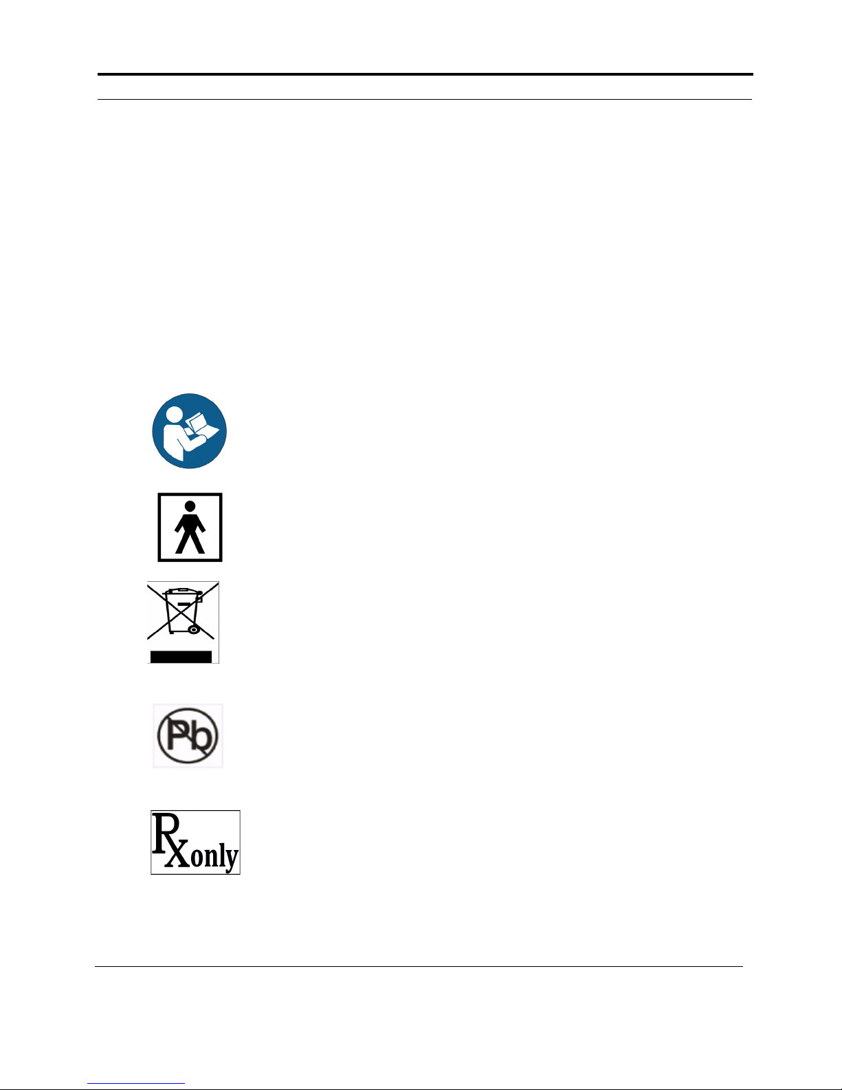
Please note that the recorder is labeled with the
following warning symbols:
.Refer to instruction manual/
booklet. Follow instructions
for use
Type BF device.
This device contains an
internal lithium battery that
may be recycled at end of
life. This device and all
other accessories should be
disposed of according to
local ordinances.
This product does not contain
lead.
Caution: Federal law restricts this device to
sale by or on the order of a
physician
LCD Display
The recorder has an LCD screen that is used to
display either time-of-day (during the recording), prompts and error messages (during the
hook-up procedure or during recording), and
lead quality (during the Holter hook-up procedure). For details about the information displayed on the LCD, refer to the hook-up
directions that follow.
Instructions to the User
About Electrical
Interference
This equipment has been tested and found to
comply with the limits for a Class-B digital
device, pursuant to Part 15 of the FCC Rules.
These limits are designed to provide reasonable
protection against harmful interference in a residential installation. This equipment generates,
uses and can radiate radio frequency energy
and, if not installed and used in accordance
with the instructions, may cause harmful interference to radio communications. However,
there is no guarantee that interference will not
occur in a particular installation. If this equipment does cause harmful interference to radio
or television reception, which can be determined by turning the equipment off and on, the
user is encouraged to try to correct the interference by one or more of the following measures:
• Reorient or relocate the receiving antenna.
• Increase the separation between the equip-
ment and receiver.
• Consult the dealer or an experienced radio/
TV technician for help.
This equipment has been certified to comply
with the limits for a Class-B computing device,
pursuant to FCC Rules. In order to maintain
compliance with FCC regulations, shielded
cables must be used with this equipment. Operation with non-approved equipment or
unshielded cables is likely to result in interference to radio and TV reception. The user is
cautioned that changes and modifications made
NorthEast Monitoring, Inc. NEMM019-Rev-O Page 5 of 35
Page 6

DR200/HE & DR300 Operator’s Manual Introduction: Patient Leads
to the equipment without the approval of manufacturer could void the user’s authority to
operate this equipment.
Patient Leads
The recorder is compatible with standard single-use silver/silver-chloride ECG electrodes.
The recorder uses NorthEast Monitoring
shielded patient cables with either seven leads
or five leads for a 3-channel Holter recording,
or three leads for 2-channel Holter recording.
For event recording, a 2- or 3-lead shielded
patient cable is used. The patient cable connects to the recorder via a 7-pin in-line receptacle.
Patient electrodes should not be applied to anything except the patient. Patient electrodes
should be left sterile in their original packaging
until use. Follow manufacturer’s instruction for
use, and discard after use. Dispose of electrodes following local ordinances and the manufacturer’s instructions.
Patient lead wires and cables should be cleaned
and disinfected as required between uses, with
70 percent isopropol alcohol and a soft cloth to
disinfect, and a non-abrasive liquid soap and
soft cloth to clean. Sterilization is not required.
Storage Capacity
The patient’s Holter data is stored in the
recorder on a removable SD Card. To store 24
hours in normal mode, the minimum capacity
of the SD Card should be 28 megabytes; 56
megabytes are required for 24 hours in high
resolution mode.
There are some SD Card types that may draw
excessive power, and will therefore drain the
battery prematurely. If you purchase cards from
a supplier other than NorthEast Monitoring, it
is recommended that you first test the SD card
for a greater amount of time than the expected
use.
The patient’s Event data is stored in non-volatile memory internal to the recorder.
Warranty Repairs
The warranty for NorthEast Monitoring products can be found on our web-site at
www.nemon.com. Contact your dealer or
NorthEast Monitoring prior to returning a
recorder for repair to determine the warranty
period, conditions and exclusions. If your
dealer is unavailable, contact NorthEast Monitoring directly.
Note: Do not pull on or stretch the patient
cables or lead wires when you clean them.
This can cause premature failure of the cable.
Instead, lay the cable and attached wires on a
clean, flat surface, hold them down with one
hand, and holding a cloth in the other hand,
rub all surfaces of the cable.
See Appendix A for details about cleaning and
disinfecting the recorder as needed.
Patient lead wires and cables should be visually
inspected between uses for worn or cracked
areas. Frequently used cables should be
replaced at least every 6 months. Worn lead
wires and cables should be replaced before
next use and disposed of following local ordinances and manufacturer’s instructions.
NorthEast Monitoring, Inc. NEMM019-Rev-O Page 6 of 35
The recorder can only be serviced or repaired
by NorthEast Monitoring or a NorthEast Monitoring authorized representative.
Prior to returning a recorder, you must obtain a
return merchandise authorization (RMA) number. This RMA number must be visible on the
outside of the packing carton, otherwise,
NorthEast Monitoring will refuse delivery. The
usable life of the device and accessories are at
least long as the warranty period.
Page 7
DR200/HE & DR300 Operator’s Manual Introduction: Operating the Recorder
Operating the Recorder
If you require assistance in setting up, using, or
maintaining your recorder, contact NorthEast
Monitoring or your dealer. Should the recorder
fail to work properly during its useful life or
changes its performance, stop using immediately
and contact NorthEast Monitoring or your dealer.
The DR200/HE and DR300 Digital Recorders
contain no user-serviceable parts. Removing
the label or opening the recorder voids the
warranty.
NorthEast Monitoring can be contacted at:
[+1]978-461-3992, toll-free in the U.S.A. at 866346-5837, or email [email protected].
The patient is not the primary operator, but may
be asked to press the Event button or transmit
events.
Care should be taken when this device is used,
especially with infants or small children, as it
includes small internal parts that could be a choking hazard. Additionally, the leads could become
entangled and could be a strangulation hazard.
Online help
In addition to the information in this manual,
more information and help can be found at our
web site, www.nemon.com or by emailing technical support at [email protected].
Our “Technical Support” page on the web-site
includes Frequently Asked Questions.
Wireless Bluetooth
(DR300 only)
The DR300 digital recorder is
enabled for wireless Bluetooth trans-
mission. In order for wireless transmission to occur, the DR300 needs to come in
range of a NorthEast Monitoring transceiver either a Gateway or a paired USB Bluetooth
adapter. Additionally, the appropriate software,
either the DR300 Socket or DR300 Bluetooth,
must be running on the computer that the transceiver is connected to.
Note: Refer to the DR300 Gateway and Socket
Technical Manual, NEMM046, for information
on how to set up and run the wireless feature.
If there is sufficient data to send and Wireless is
turned on, the recorder will attempt to locate a
Gateway every 20 minutes. When a paired Gateway is found, the data will attempt to be sent. If a
paired Gateway is not found, and the recorder is
in Event mode, it will attempt to look for a paired
Bluetooth Adapter on a PC to send the data.
Note: If you are using the USB Bluetooth
adapter, there can be only one paired adapter in
a given location, such as an office.
At any point, if there is at least one event or 20
minutes of Holter data, the user can force the process by pressing the ENTER button on the
recorder. For a Holter Bluetooth transmission,
only manually initiated transfers are allowed. This
ensures that only one recorder is transmitting at
one time while in the office.
The most current version of this manual, the warranty and our software can always be found on
our web-site on the “Downloads & Documents”
page.
NorthEast Monitoring, Inc. NEMM019-Rev-O Page 7 of 35
DR300 Tablet App
Because of the DR300’s unique Bluetooth capability, you can use an Android tablet to set up and
start the DR300. The DR300 tablet App is downloadable via Google Play and more information
can be found in Chapter 5- DR300 Tablet.App.
Page 8

Chapter 2 -Holter Recording
The Holter Recording Procedure
To use a DR200/HE or a DR300 digital recorder to record a patient’s long-term ECG
(Holter), follow the appropriate steps listed below:
Step 1 - Hook-up patient;
Step 2 - Prepare the recorder
Step 3 - Enter patient ID on recorder;
Step 4 - Start recording.
These steps are described in detail starting with the next section.
If you have a new SD Card that has not been formatted with a flash.dat file, you will
need to use your NorthEast Monitoring, Inc. Holter LX Analysis software to initialize
the card for the first time.
When the recording is finished, simply remove batteries to stop recording.
Step 1: Hook-up Patient for Holter
The most important element in Holter monitoring is recording a clean long-term ECG
signal. Because a clean signal is directly dependent on the hook-up procedure, great
care should be taken when hooking up the patient. Poor hook-up causes poor signal
quality and artifact.
To ensure proper hook-up, follow these steps:
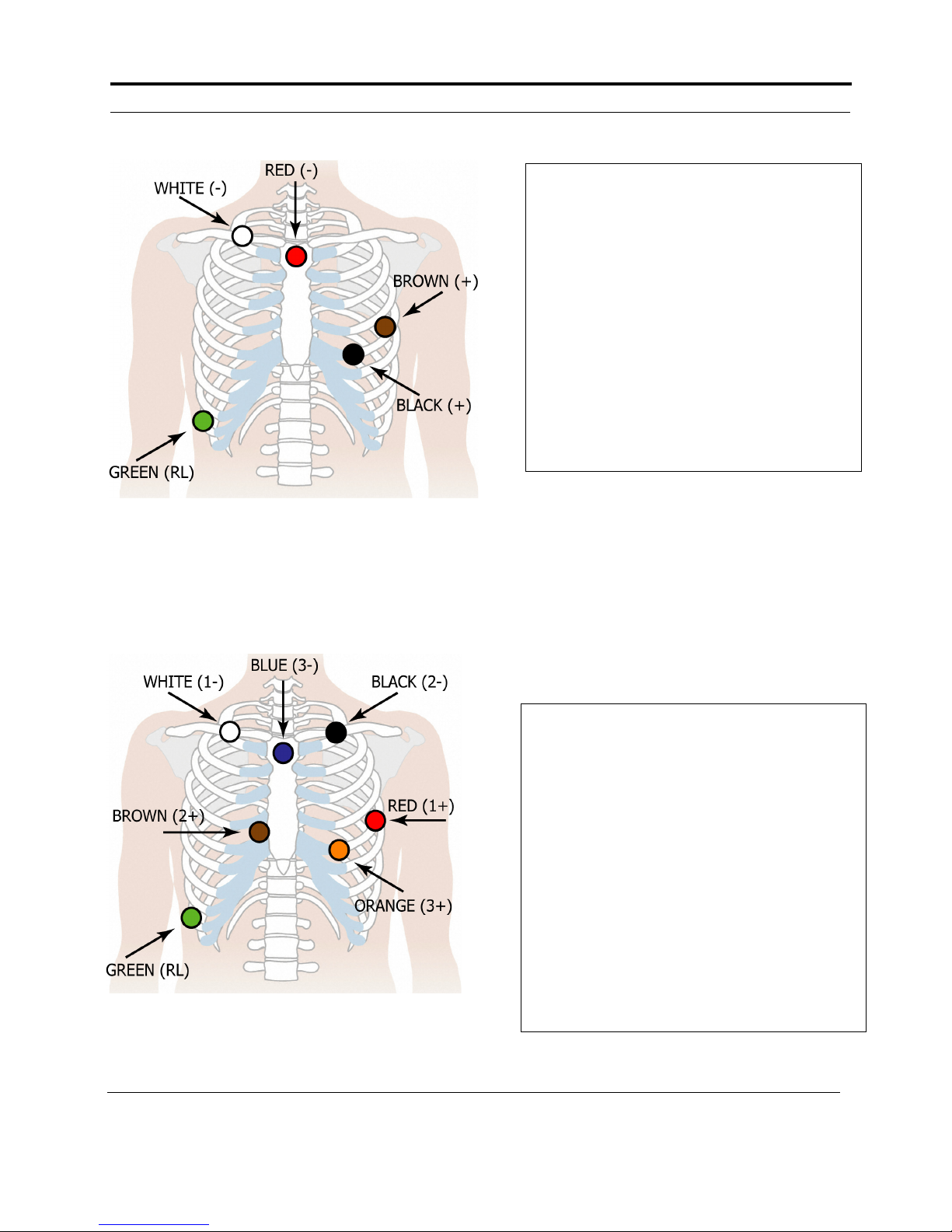
1. Using either the 5-Lead (3-channel) or 7-Lead (3-channel) hook-ups shown, identify
sites for the electrodes. You can also choose a 3-Lead hook-up (2-channel) which is
shown in the Event section of this manual.
2. Prepare the patient’s skin. If the patient has hair in any of the electrode areas, shave
it with a safety razor. Use an alcohol pad and rub the sites briskly until the skin reddens. Let the skin air dry before proceeding.
3. Attach the patient cable to the recorder. Next, snap a lead wire from the patient cable
to each of the electrodes.
NorthEast Monitoring, Inc. NEMM019-Rev-O Page 8 of 35
Page 9
DR200/HE & DR300 Operator’s Manual Holter Recording: The Holter Recording Procedure
5-LEAD PLACEMENT
7-LEAD PLACEMENT
5-LEAD PLACEMENT
Channel 1:
+ Brown 5th rib, left anterior axillary line
- Red centered
Channel 2:
+ Black 5th rib, left of mid-clavicular line
- Red
Channel 3:
+ Black
- White right manubrium
Ground:
Green centered over rib
7-LEAD PLACEMENT
Channel 1:
+ Red 5th rib, left anterior axillary line
- White right manubrium
Channel 2:
+ Brown 2 cm. right of xiphoid process
- Black left manubrium
Channel 3:
+ Orange 5th rib, left of mid-clavicular line
- Blue centered on manubrium
Ground:
Green centered over rib
Note: The 7-lead hook-up shown below consists of
independent bipolar leads and corresponds to IEC606012-47 requirements (Code 2). The 5-electrode hook-up
does not have independent leads, and so, does not correspond to either Code 1 or 2, but is widely used in the
United States and Canada.
NorthEast Monitoring, Inc. NEMM019-Rev-O Page 9 of 35
Page 10
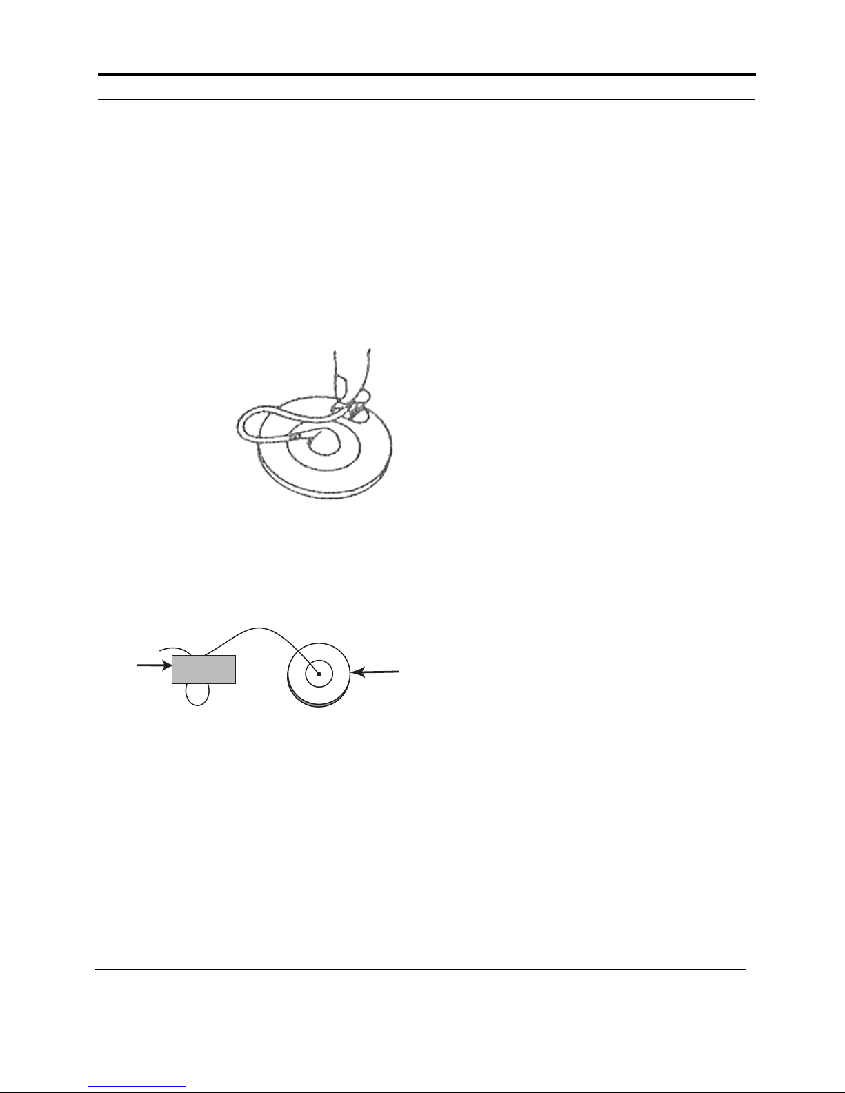
DR200/HE & DR300 Operator’s Manual Holter Recording: The Holter Recording Procedure
Using a clip lock electrode
Electrode
Tape
Stress Loop
4. Attach an electrode at each of the patient’s
prepared sites. As you attach electrodes, be
careful to not let any unattached electrode
come in contact with other conductive
objects, including ground. Be sure to refer
to the diagrams on the previous page for
correct placement of each colored lead. The
electrodes should be placed over bone at
each of the sites. Press the center of each
electrode against the patient’s skin, then rub
the outer circle of each electrode to secure
it.
5. If you use
lead lock
or clip
lock electrodes, be
sure to use
the lock or
clip to
relieve
stress on
each lead
wire; refer
to the diagram at right for proper use. Otherwise,
tape each lead wire into a stress loop (see
the diagram below) to help prevent movement of the electrode.
contacts down and toward the recorder as
you gently push it in. Be sure to use the SD
Card you formatted for this patient.
If the card pops out slightly when you push
it in, try again. Pushing gently on the card
both inserts it and allows you to remove
it. Never pull the card out as it will damage the recorder.
Note: The SD Card should slide in easily.
Make sure you do not force the card in; if
you force the card in upside-down or force
the card out by pulling, it can damage the
connector inside the recorder.
3. Insert a fresh 1.5 volt AA battery into the
battery compartment, being sure to orient it
as indicated in the diagram inside the compartment. See Appendix B for details about
battery choices.
4. Replace the battery cover by sliding it into
the card slot until it clicks.
5. “DR200/HE” or “DR300” will first appear
on the screen and then the NorthEast Monitoring information will appear. Press
ENTER to continue.
6. If you did not erase the previous patient’s
data from the SD Card, you will now be
prompted to Erase memory. Use the green
arrows to select “*Yes” and press ENTER.
7. You will see ERASE DONE when erasing
is complete.
Step 2: Prepare the Recorder
After connecting the patient to the recorder,
follow these steps to prepare the recorder:
1. Remove the battery cover from the back of
the recorder. The battery compartment and
the SD Card slot are now exposed.
2. With the recorder front facing up and away
from you, insert an SD Card into the slot.
The SD Card should have the connector
NorthEast Monitoring, Inc. NEMM019-Rev-O Page 10 of 35
Note: If at any time you need to restart the
set up process, just remove the battery to
begin again.
Note: If your recorder is in Event mode, the
15-second countdown will begin when you
put in a new battery. To interrupt the 15second countdown, quickly press ENTER,
down arrow, up arrow and then EVENT, in
that order. You should now see the NorthEast
Monitoring screen. Press ENTER to continue
to the main menu.
Page 11

DR200/HE & DR300 Operator’s Manual Holter Recording: The Holter Recording Procedure
Step 3: Enter Patient ID
You will now see a screen with two choices:
“New Patient” and “Settings”. Since the
recorder will store settings between patients,
you may only need to adjust settings when
there is a time change or if you want to change
between Holter and Event. For more information on adjusting settings, refer to Chapter 4 Recorder Settings and Messages.
1. If you would like to input the Patient ID at
this time, press ENTER and use the green
up arrow to select the first character of the
ID. Use the ENTER button when you have
entered the first character and continue until
all of the ID is entered. Once the patient ID
is entered, press the EVENT button.
Note: If you make an error while entering a
character into the Patient ID, you can
backspace one or more times by holding down
the Enter key for several seconds until the
cursor moves to the left.
2. Now, the LCD will display the ECG sig-
nals, the battery level, and lead quality
based on the level of impedance detected
between the two electrodes for each channel. Lead quality for each channel is a number between 0 and 5. The best possible
signal quality reading is 5; that indicates a
good electrode-skin connection. A “0” indicates no signal is being received by on the
recorder.
3. Once a satisfactory lead quality signal of 3
or more is displayed for all channels, continue with the final step - Start Recording.
Note: If you do not push the EVENT button,
the recorder will display lead quality for 10
minutes, then start recording. To delay the
start of recording, simply press the EVENT
button briefly and the 10-minute countdown
will start again.
Step 4: Start Recording
1. Once the LCD displays satisfactory lead
quality signals for all channels, you can
start the recording by pressing the EVENT
button for 3 seconds till you see “Recording
Started”. If you do not do this, recording
will begin automatically after 10 minutes.
During recording, time-of-day appears on
the LCD. Once recording begins, it will
continue until the battery is removed or the
SD Card is full.
2. The patient can choose between a belt clip
or pouch with strap for wearing the
recorder. All equipment, except the electrodes and a portion of the lead wires,
should be over at least one layer of clothing
so that it is not in direct contact with the
patient’s skin. Orient the recorder on the
patient so that the EVENT button is accessible and the LCD is visible.
3. Advise the patient to not expose the
recorder or electrodes to any wet environment; in addition, they should not shower,
bathe, or swim while wearing the recorder.
4. Instruct the patient on how to use the
EVENT button to indicate symptomatic
events or activities of interest during the
Holter test. Advise them to push the
EVENT button briefly. The patient may
also be given the opportunity to enter a
diary at the time of the event. They should
use the up/down arrows to choose the most
appropriate entry.
The EVENT button then marks the recording so that when the Holter signal is analyzed, the ECG at the time-of-day the
button was pushed is kept as saved strips
and labeled as an event and with the
selected diary entry.
5. When the patient returns, remove the elec-
trodes, leads and recorder from the patient.
Open the recorder and remove the battery
and SD Card from the recorder. Pushing
gently on the card both inserts it and
allows you to remove it. Never pull the
card out as it will damage the recorder.
NorthEast Monitoring, Inc. NEMM019-Rev-O Page 11 of 35
Page 12

DR200/HE & DR300 Operator’s Manual Holter Recording: Power Loss Protection Feature
The Holter signal is now ready to be analyzed.
Note: For a DR300, instead of removing
the SD card, you could choose to
wirelessly transmit the recording using a
paired Bluetooth adapter. Refer to the
DR300 Gateway and Socket Technical
Manual, NEMM046, for information on
how to set up and run the wireless feature.
If you are using the USB Bluetooth
adapter, there can be only one paired
adapter in a given location, such as an
office.
Power Loss
Protection Feature
In Holter recording mode, as of software version 4.41, if the battery is removed and reinserted within 12 hours, the recording will
continue. (As of firmware version 1.09, restart
time is up to 60 minutes, but for firmware versions 1.08 and earlier, it is only up to 10 minutes.)
When the battery is reinserted during the
allowed time, the LCD returns to the time-ofday and continues to record the patient’s Holter
signal. When the patient’s recording is analyzed, the signal recorded while the batteries
were not in place appears as continuous highfrequency artifact in all channels.
If the battery is left out for more than 12 hours,
recording cannot be restarted. Instead, you will
have to use the recording as is, or you will have
to re-initiate the recording after erasing the
memory on the SD Card.
Note: If the SD Card has been removed and
you wish to restart the recorder without a card
in order to update settings, you will need to
press the following buttons in this exact order
during the 15 second countdown: ENTER,
down arrow, up arrow, EVENT.
NorthEast Monitoring, Inc. NEMM019-Rev-O Page 12 of 35
Page 13
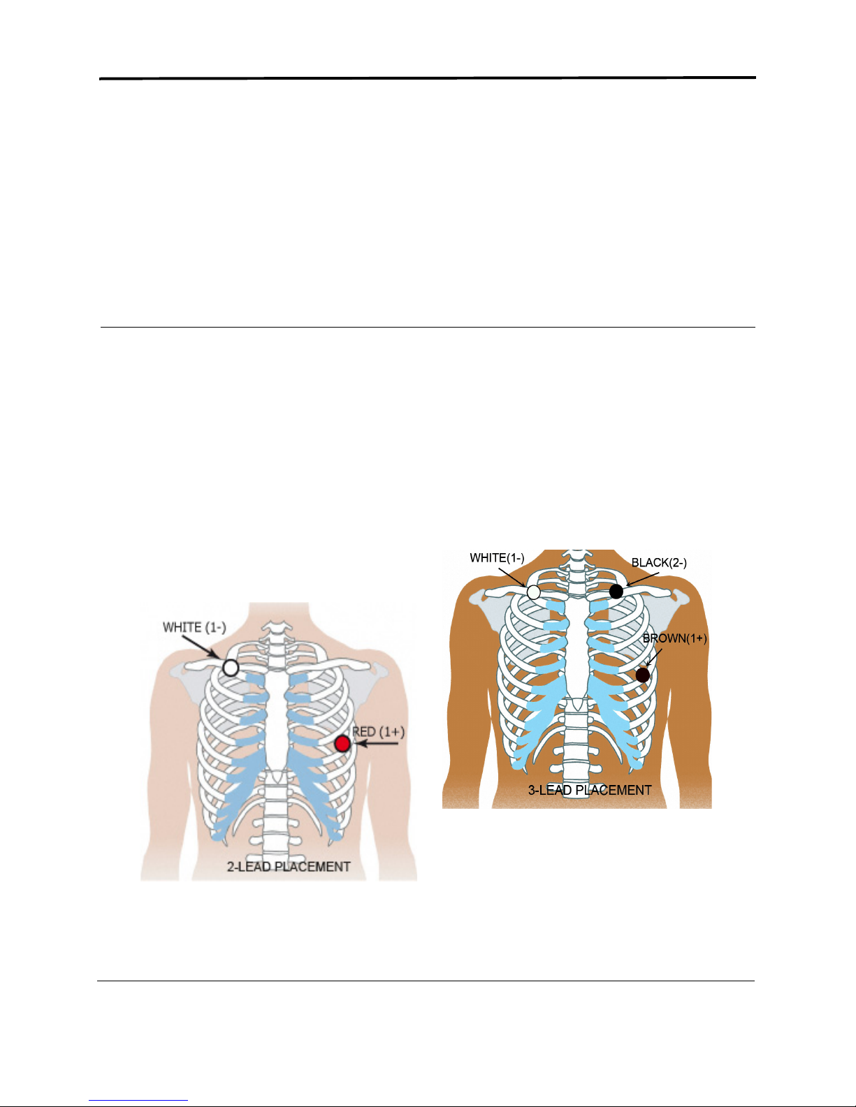
Chapter 3 -Event Recording
Channel 1:
+ Red: 5th rib, left anterior axillary line
- White: Right manubrium
Channel 1 (Lead 1):
+ Black: Left-mid-clavicular
- White: Right mid-clavicular
Channel 2 (Mod V5):
+ Brown: 5th rib, left anterior axillary line
- White
The Event Recording Procedure
The DR200/HE and DR300 digital recorders can be used as a looping event recorder to capture
events automatically or when activated by the patient. Based upon your settings, the recorder
can capture up to 90 minutes of event recordings. When one or more events are captured, the
patient may transmit his/her recordings transtelephonically.
Note: No SD Card is used during event recording.
To record in Event mode, follow these steps:
Step 1 - Hook-up the patient;
Step 2 - Prepare the recorder;
Step 3 - Start recording.
NorthEast Monitoring, Inc. NEMM019-Rev-O Page 13 of 35
Page 14

DR200/HE & DR300 Operator’s Manual Event Recording: The Event Recording Procedure
12:33
Sent
10 / 100
96
Step 1: Hook-up Patient
The recorder uses a 2-electrode lead for 1channel or an optional 3-electrode lead for 2channel event recording.
Refer to Step 1: Hook-up Patient in the Holter
Recording section of this manual for hook-up
instructions, but refer to the 2- or 3-electrode
diagram on this page for electrode placement
instructions.
Step 2: Prepare the Recorder
After connecting the patient to the recorder,
follow these steps to prepare the recorder:
1. Remove the battery cover from the back of
the recorder. Now the battery compartment
and the SD Card slot are exposed.
2. If there is an SD Card in the recorder, it
should be removed for event recording as it
will drain the battery unnecessarily. To
remove the SD Card, gently press on it and
it should pop out slightly. You should be
able to pull it out easily. If it doesn’t work
the first time, try again.
3. Insert a fresh 1.5 volt AA battery into the
battery compartment, being sure to orient it
as indicated in the diagram inside the compartment. The battery sits loosely in the
compartment. See Appendix B for details
about battery choices.
4. Replace the battery cover by sliding it into
the slot until it clicks.
5. The text “DR200/HE” or “DR300” will first
appear on the screen and then after 10 seconds, the recorder will begin counting down
from 15 seconds and will automatically
begin recording. The time-of-day and battery level will appear on the display once
recording has begun. If LCD also shows
events stored on the recorder, regardless of
whether they are sent, you need to erase
them now.
6. If the recorder is in Holter mode, you will
get an error asking for an SD Card which
will then alternate with a 15-second countdown. Interrupt the countdown with the
button sequence, ENTER, down arrow, up
arrow and EVENT and the go to the General Settings menu to change the Recording
Type from Holter to Event. After doing that,
go back to “Return” on the menus until
recorder and the 15-second countdown
begins again. Event recording will start
after 15 seconds.
To Erase Events: If
the previous patient’s
events still exist on the
recorder and they have
been transmitted or
stored, you will see the
word “Sent” on the
LCD screen and you
must erase the events before hooking up the
new patient. To erase the events, hold down
either green arrow button for 3 seconds. You
will see “ERASING MEMORY” and once
memory has been erased, the event counter at
the bottom of the LCD screen will be reset and
the word “Sent” will be replaced with the word
“Recordings”.
If the previous patient’s recordings were not
“Sent” then you will need to transmit or store
event data before erasing. For more information on saving event data, refer to “To Transmit
or Store Events” on the next page.
To Adjust Settings: In order to adjust settings,
you will need to press the following buttons in
this exact order during the 15 second countdown: ENTER, down arrow, up arrow,
EVENT. While in Event mode, to restart the
countdown, simply remove and reinsert the
battery.
For more information on settings and how to
adjust them, refer to Appendix C.
Note: If at any time you need to start the set
up process over, just remove the battery to
begin again.
NorthEast Monitoring, Inc. NEMM019-Rev-O Page 14 of 35
Page 15

DR200/HE & DR300 Operator’s Manual Event Recording: To Transmit or Save Events
Step 3: Start Recording
1. The recording will begin automatically after
15 seconds. At first you may see the ECG
signal and quality on the screen. The quality
can range anywhere between 0 (no signal)
to 5 (best signal). A rating of 3 or above
should suffice, although you may want to
get a signal of 5 before continuing. To view
the ECG again, just remove the cable and
re-insert. There will be a 10-second delay.
2. During recording, time-of-day appears on
the screen. Once recording begins, it will
continue to record until the battery is
removed or the memory is full.
3. The patient can choose between a belt clip
or pouch with strap for wearing the
recorder. All equipment, except the electrodes and a portion of the lead wires,
should be over at least one layer of clothing
so that it is not in direct contact with the
patient’s skin. Orient the recorder on the
patient so that the EVENT button is accessible and the LCD is visible.
4. Advise the patient to not expose the
recorder or electrodes to any wet environment; in addition, they should not shower,
bathe, or swim while wearing the recorder.
5. Instruct the patient how to use the EVENT
button to record symptomatic events.
Advise them to push the EVENT button
briefly; when they use it depends on your
institution’s procedures.
Note: Although the recorder’s false negative
rate is low, there is always the potential that
an arrhythmic event being experienced by a
patient is not captured automatically by the
recorder. Therefore, we strongly recommend
that even when automatic detection is turned
on, that patients be informed that they should
always press the EVENT button when they
feel they are having an arrhythmic event.
6. If you choose, instruct the patient when and
how to send the recordings via the telephone.
7. When the patient returns, review the screen
first to ensure that all events have been sent.
8. If the screen states that there are “Events
Recorded” and does not state that any were
“sent”, you will now need to transmit and
save the events for the patient.
To stop recording
After transmitting and erasing any unsent
events, remove the electrodes, leads and
recorder from the patient. You should now
open the recorder and remove the battery to
stop operation.
To Transmit or Save Events
At the beginning of the transmission a cal signal will be present. Additionally, at the beginning of each event there will be a marker. The
marker is a digital signal that will include the
serial number of the recorder and the time, date
and type of each event. The digital signal can
only be read by the NorthEast Monitoring LX
Event software. If you are using a different
event recorder software, you will not be able to
read the digital signal, but the signal will allow
you to tell where each event begins.
There are a few ways to obtain the event data
that has been saved on your recorder:
1. Acoustic Transmission
Start the software application or recording
device that will be recording the events. Once
recording has begun, press the ENTER button
on the recorder for a second and the events will
begin transmitting. Transmission will continue
until all events are sent. Once the events are
sent, you can now erase them from the recorder
by pressing either one of the green arrows for 3
seconds.
The recorder’s ECG transmission uses the standard FM transmission. The header uses a proprietary format.
NorthEast Monitoring, Inc. NEMM019-Rev-O Page 15 of 35
Page 16

DR200/HE & DR300 Operator’s Manual Event Recording: To Transmit or Save Events
2. SD Card storage
LX Event users can choose to store events on an
SD Card. Before an SD Card is used for the first
time, it must be formatted using the LX Event
software. Also, only one set of data can exist on
a card at any one time, so be sure that you save
the previously stored data on the computer
before beginning. (For more information on
formatting the SD Card, please refer to your LX
Event Software manual.)
To record the events onto a pre-formatted card,
refer to the following steps:
1. Remove the battery cover from the back of
the recorder. The battery compartment and
the SD Card slot are now exposed.
2. With the recorder front facing up and away
from you, insert an SD Card into the slot.
The SD Card should have the connector contacts down and toward the recorder as you
gently push it in. If the card pops out slightly
when you push it in, try again. Pushing gen-
tly on the card both inserts it and allows
you to remove it. Never pull the card out
as it will damage the recorder.
Note: The SD Card should slide in easily.
Make sure you do not force the card in; if you
force the card in upside-down or pull it out, it
can damage the connector inside the recorder.
3. Re-insert the battery into the recorder, being
sure to orient it as indicated in the diagram
inside the compartment.
4. A message on the LCD screen will now
appear - “COPYING EVENTS.” When the
events are finished being copied to the SD
Card, you will see the message “FINISHED
REMOVE CARD.” Do as you are told by
gently pressing down onto the SD Card. It
should pop out.
5. You should now insert the SD Card into your
reader and save the data on your computer
using the LX Event software. If you use the
card again before saving on your computer,
the data will be lost.
6. Once the events are saved on the desktop, re-
insert the battery into the recorder and see
the word “Sent” on the screen above the
Event tally. You should now erase the events
from the recorder by pressing either green
arrow for 3 seconds.
3. Wireless Transmission (DR300
only).
Refer to the DR300 Gateway and Socket Technical Manual, NEMM046, for information on
how to set up and run the wireless feature.
In short, if you choose to do a wireless transmission, you must turn on the Wireless setting on
the DR300 and send the patient home with the
paired Gateway. Then, the DR300 Socket program will collect and save event files during the
procedure.
If the DR300 recorder returns with unsent procedures and Wireless is turned on the recorder,
then you can use the paired Gateway or a local
Bluetooth adapter to record the events in the
office. Pressing the ENTER button will initiate
the transfer of data locally. Be sure to immediately delete the events by pressing a green arrow
for 3 seconds, or the events may be resent.
Note: If you are using the USB Bluetooth
adapter, there can be only one paired adapter
in a given location, such as an office.
NorthEast Monitoring, Inc. NEMM019-Rev-O Page 16 of 35
Page 17
DR200/HE & DR300 Operator’s Manual Event Recording: Event Recording: Patient Operating Instructions
12:33
Recordings
10 / 100
89
89
12:39
Sent
10 / 100
Event Recording: Patient
Operating Instructions
The recorder is ready to use when you receive
it from your physician or nurse.
To Hook-up:
You will want to reapply fresh electrodes daily.
To do this, simply snap lead wires into new
electrodes first and then apply according to the
technician’s instructions. We recommend that
you do this after bathing or showering as the
recorder or electrodes should not get wet.
To Record an event:
If your recorder has an automatic mode, the
recorder may record events without your
knowledge. This is normal operation and you
may hear a beep when the recorder is recording
an event.
If you feel that it is time to record an event
manually, simply press the EVENT button and
hold for a second. If your recorder is set up to
accept a diary entry, you will see the word
“Manual Event” on the recorder. No further
action from you is required.
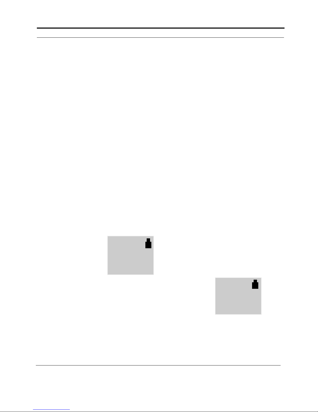
After recording is complete, the screen will
show the time, the
word “Recordings”
and a tally showing the
number of events that
were recorded and the
total number of events that can be stored on the
recorder. In this example, the patient has 10
events recorded out of a possible 100:
To Send events manually:
If you have been instructed by your technician
to call the receiving center after time has
passed or a certain number of events have been
recorded. Your recorder may even beep and/or
display a phone number when it is time to call.
When it is time to call, please do the following:
Step 1: If the recorder is in a pouch, remove the
cable from the recorder and remove the
recorder from the pouch. If the recorder is not
in a pouch, it is not necessary to remove the
cables from the recorder at this time, but you
can do so if it makes it easier for you. Now, set
the recorder on a flat surface with the screen
side up and within reach of your telephone.
Note: Cell phones DO NOT work for sending
transmissions.
Step 2: Call the receiving center phone number
provided by the technician.
Step 3: When the phone is answered, follow
the instructions given to you by the technician
on the other end of the line.
Step 4: When instructed to “send your events”,
do the following:
1. Press the ENTER button that is located on
the bottom left corner of the recorder.
2. Gently rest the telephone on the table with
the mouthpiece over the speaker that is
located between the ENTER button and the
down green arrow on the recorder.
3. The screen will display a message “Sending
Event” with the number of the event that
the device is currently sending and the total
number of events it needs to send. (You
may also be able to hear the events being
sent over the phone line.) This process may
take just a few or many minutes depending
upon the number of events recorded and the
amount of time of each event.
4. Once all the events
are sent, you will
now see that the
word “Sent” has
replaced the word
“Recordings”. This
means that all of
the events in the recorder have been sent,
but are still saved.
NorthEast Monitoring, Inc. NEMM019-Rev-O Page 17 of 35
Page 18

DR200/HE & DR300 Operator’s Manual Event Recording: Event Recording: Patient Operating Instructions
89
12:45
Recordings
0 / 100
Step 5: At this time the
technician may ask you
to erase your events by
pressing either of the
green arrow buttons
down for 3 seconds,
but you SHOULD
ONLY ERASE EVENTS WHEN
INSTRUCTED TO DO SO. Once events are
erased, you will see that the first number is
changed to 0 as there are no longer any events
stored on the recorder. You are now ready to
record new events.
Wireless Event Transmission:
If your DR300 digital recorder is set up to do
automatic wireless transmissions, you do not
need to send events manually. Instead, when
the recorder comes in contact with the NorthEast Gateway box, that has been provided to
you, it will automatically send any events that
are saved every 20 minutes.
Cleaning
You can clean the outside of the recorder with a
soft cloth.
your next transmission is successful, be
sure to replace the battery before you send
any transmissions to the receiving center.
• Battery FAILURE: Recording has
stopped. Replace the battery as soon as possible.
• LEAD LOOSE: This error will occur when
there is a problem with the patient hook-up.
The problem may be with an electrode, a
lead, or the cable that connects the leads to
the recorder. Please check all of the connectors to be sure that they are still in place. If
you continue to see this error after 10 seconds, call the receiving center for further
assistance.
Batteries
Your battery should last for the duration of
your test, but if you need to change the battery,
you can do so at any time and not lose any
event data stored on the recorder.
To replace the battery, insert a blunt object (for
example, pen, coin or non-pointy tool) in the
space between the battery and the top edge of
the recorder. Press gently to easily remove the
battery.
LCD Screen Messaging
Error messages may occur during recording. If
you see an error message that is not listed on
this page call your receiving center for further
instructions.
• If the time and event tally appears on the
screen, this is normal and means that the
recorder is functioning appropriately.
To insert a fresh battery into the battery compartment, be sure to orient it as indicated in the
diagram inside the compartment. The battery
sits loosely in the compartment.
Note: Do not leave batteries in the recorder
for extended periods (more than two weeks)
when the recorder is not in use.
• If the screen is blank, this means that the
recorder is not working. It is possible that
the battery no longer has enough power. Try
putting in a fresh battery, but if this does not
solve the problem, call your receiving center for further instructions.
• Battery LOW: Battery power is running
low. When this message first appears, you
will have about 5 days of recording time
left on your battery. In order to ensure that
NorthEast Monitoring, Inc. NEMM019-Rev-O Page 18 of 35
Page 19

Chapter 4 -Recorder Settings,
Error Messages and
Troubleshooting
For Holter recording, you can adjust settings on the recorder between patients only. To begin,
insert a battery to start the recorder.
If 15-second countdown occurs
If your recorder is in Event mode, the 15-second countdown will begin when you put in a new
battery. To interrupt the 15-second countdown, quickly press ENTER, down arrow, up arrow
and then EVENT, in that order. You should now see the NorthEast Monitoring screen. Press
ENTER to continue to move to the main menu.
To Adjust Settings
To adjust the settings, use the green arrows to move up and down between the menu items and
ENTER to accept. The cursor “>” will appear next to the item that you are able to update. Press
ENTER to begin updating that item, and then use the green arrows to adjust the value. When
finished adjusting a value press ENTER to save the value. To return to the previous menu, use
the green arrows to move the arrow to “Return” at the top of the menu and press ENTER.
To Review Settings
At any time, you can remove the battery from the recorder and re-insert. Then interrupt the 15second countdown as instructed above. You can now review settings without losing any event
data.
To Update Time and Date
The recorder should save the correct time and date between uses, but if you ever need to update
the time or the date, move the cursor to “Time and Date” and press ENTER. You can now
update Hour, Minutes, Day, Month or Year by moving the cursor with the green arrows and
pressing ENTER.
About
To view the Serial No, the customer code (cc), the Version number of the software on the
recorder, the build number for that software, and the number of times the recorder has been used
in Holter mode.
NorthEast Monitoring, Inc. NEMM019-Rev-O Page 19 of 35
Page 20

DR200/HE & DR300 Operator’s Manual Recorder Settings, Error Messages and Troubleshooting:
To Update General Settings
Contrast. Use arrows to increase or decrease
contrast.
Lead Loose.
• On - Lead Loose message is enabled.
• Off - Lead Loose message is disabled.
Event marker. When on, the ECG will be
labeled with one second of 6-cycle square
wave where the event took place.
Key mode.
• Normal - Sound enabled and no delay;
• Delayed - Patient will need to press Event
and Enter buttons for several seconds in
order to prevent false entries, and sounds
enabled; or
• Quiet - Sound disabled. No delay.
Rec Type. Switch between Holter, Event and
Both-HE recording. The Both-HE setting is
for Event recording where you desire a Holter
back-up file to be saved. For Both-HE, you will
need to put an SD flashcard with a flash.dat file
into the recording as if you were doing a Holter
recording. The flash.dat file should be large, so
chose “file as large as card” from the Initialize
Flashcard options in Holter LX Analysis.
Menu Lock. Menu Lock will prevent anyone
from reviewing or updating any other settings.
• To lock the menu, enter 217.
• To unlock the menu, enter 151.
Language. Select from U.S. English, International English, Danish, Finnish, German,
French, Italian, Norwegian, Polish, Portuguese,
Russian, Spanish and Turkish.
Diary. When the Diary is turned On, the
patient will be able to select a symptom during
a manual event. During Event recording only,
Post Event Seconds must be is set to 30 or
greater, for the Diary options to be displayed to
the patient.
Hi Res / ch: For release 4.46, only 3 channel
and Hi Res recording function correctly.
Holter 1 & 2 channel should not be used.
When turned On, the recorder will record
Holter in high resolution. High resolution mode
provides enhanced R-wave reproduction for
pediatric recordings.
Wireless. (DR300 only) When the Wireless
setting is turned On, the DR300 recorder will
transmit saved event or Holter through a paired
NorthEast Monitoring Gateway box.
Note: Each Event must be 8 minutes (480
seconds) or shorter in length in order to be
transmitted via the Gateway.
The URL settings tell the recorder where to
ultimately send the data when Wireless is
turned on. The URL settings are pre-programmed and cannot be changed by the technician.
Pair Bluetooth - Refer to the DR300 Gateway
and Socket Technical Manual, NEMM046, for
information on how to set up and run the Wireless feature.
Event Settings
Pre Event Sec. The number of seconds saved
before the EVENT button is pressed by the
patient.
Post Event Sec. The number of seconds saved
after the EVENT button is pressed by the
patient. If this number is set to 15 seconds, the
user will not be asked to select a diary entry
after pressing the record button.
Max Events. Limits the number of events that
are saved at any one time. A total of 90 minutes
can be saved on the recorder. The maximum
number of events may be automatically
adjusted by the recorder based on the number
of seconds saved for each event as well as the
number of channels.
NorthEast Monitoring, Inc. NEMM019-Rev-O Page 20 of 35
Page 21

DR200/HE & DR300 Operator’s Manual Recorder Settings, Error Messages and Troubleshooting:
Channels. For event recording, the recorder
can record either one or two channels. If two
channel recording is selected, the recorder will
transmit both channels sequentially during the
transmit process. A 3-lead cable is required for
2 channel recording.
Acoustic mode settings
Note: LX Event version 2.11c and earlier
versions support acoustic mode for event
recording.
Note: These settings are disabled if a DR300
is set to transmit wirelessly.
Send Setting. The Speed setting allows you to
transmit either 1, 3 or 4X speeds.
Call message. Once events are recorded, you
can inform the patient with either a sound or a
phone number on the LCD screen:
• Phone Num - Will show the entered phone
number on the LCD screen after events are
recorded. “Any” will show number if there
is one or more events, “Full” will show
number only if maximum number of events
have been recorder.
• Enter Phone Num - Enter the phone num-
ber that the patient should call when events
recorded. Use green arrows to update digits.
Hold down ENTER button to backspace.
• Reminder - Will cause the recorder to beep
repeatedly after events are recorded.
“Any” will beep if there is one or more
events, “Full” will beep only if maximum
number of events have been recorder.
Auto Detect Settings
Auto Detect. Turns auto detection On/Off for
all event types, including AF.
AF Detect. Only turns Atrial Fibrillation
detection On/Off.
AF Peak HR. The minimum HR that at least 3
beats of the previous 20 must exceed, in order
for an event to be called AF. The range s 60 120 BPM.
Brady Limit. If a heart rate on or below this
number is detected, an event will be recorded.
A range of 20 - 100 BPM is allowed.
Tachy Limit. If a heart rate on or above this
number is detected, an event will be recorded.
A range of 50 - 300 BPM is allowed.
Pause Limit. If no heart beat is detected for at
least the pause length in seconds, an event will
be recorded. A range of 1.0 to 10.0 seconds is
allowed.
Separation. There are two options. Both limit
the number of events by type by requiring a
minimum amount of time between the same
type of event.
• The first, Min Time, applies to all events,
except AF. A range of 2 - 20 minutes is
allowed.
• The second “Min AF time”, applies to AF
events only. A range of 2 - 90 minutes is
allowed.
NorthEast Monitoring, Inc. NEMM019-Rev-O Page 21 of 35
Page 22

DR200/HE & DR300 Operator’s Manual Recorder Settings, Error Messages and Troubleshooting: Error Messages
Error Messages and
Troubleshooting
If you see the time-of-day on the recorder
screen, the recorder is recording.
Note: If the LCD screen is completely blank,
this means that the recorder is not recording.
An error message will appear when there is a
problem with the recorder. The recorder may
display the following error messages:
Battery LOW: Battery is running low. When
this message first appears, you will have about 5
days of recording time left on your battery.
Battery FAILURE: Recording has stopped.
Card Erase ERROR: An error was found
while attempting to erase the SD Card. This
usually means a defective card.
LEAD LOOSE: This error will occur when
there is a problem with the patient hook-up. The
problem may be with an electrode, a lead or the
cable that connects the leads to the recorder. The
LEAD LOOSE message will remain on the
screen for about 10 seconds after the problem
has been corrected. This error message can be
turned off in General Settings.
Explorer to identify and delete these files. The
only file allowed is flash.dat.
Short recording: There are some SD Card
types that may draw excessive power, and will
therefore drain the battery prematurely, resulting in a short recording. If you purchase cards
from a supplier other than NorthEast Monitoring, it is recommended that you first test the SD
card for a greater amount of time than the
expected use.
Unable to write SD: An error was found while
attempting to write to the SD Card. This message occurs when the card is full. Sometimes
this message will appear when a card is defective.
Write Timeout error: This usually means a
defective card.
Missing SD Card: There is no SD Card in the
device. A card is required for Holter recording.
SD Access: Unable to read the SD Card. This
usually means a defective card.
SD Card is write locked: Write Lock tab is set
on the SD Card. Unlock Write Lock tab and try
again.
SD Setup Failure: Failure during write of
patient ID to SD Card. You will need to re-initialize your card using the LX software.
SD Card Incorrectly erased: There may be
disallowed files on the SD Card. Remove SD
Card from recorder and use card reader and
NorthEast Monitoring, Inc. NEMM019-Rev-O Page 22 of 35
Page 23

Chapter 5 -DR300 Tablet App
The DR300 Android Tablet Application allows you to update recorder settings, view ECG signals, and start the DR300 recorder all from your tablet.
Installing the DR300 Tablet Application
The DR300 Tablet App was tested on a Samsung tablet and requires Android version 5.1. The
DR300 Tablet App can be found and downloaded via Google Play. There is no cost for this application. Install the App onto your tablet before pairing with the DR300 recorder.
Pairing the recorder with the Tablet
Before pairing, make sure that there are no events or a flash.dat card with data that you want to
keep in the recorder.
1. First, start the DR300 recorder and go to Settings > General Settings > More > Wireless >
Pair Bluetooth. At this point the DR300 recorder turns on its Bluetooth and looks for a pairable device. If it is not already paired, it should respond with “no connection”. That is good.
Leave the recorder at this screen.
2. Next, go to the Bluetooth Settings on the tablet. You should see the DR300 recorder on the list
of devices that have been found under “Available Devices”. Click on the recorder that you
want to connect to.
3. The tablet should ask for you to Confirm the pairing. Do so.
4. Shortly thereafter, you should see “Found Tablet” appear on the DR300 recorder.
5. Now, restart the recorder by removing and reinserting the battery. Once you see the initial
splash screen, with “NorthEast Monitoring” at the top, you can start using the DR300 Tablet
App with the DR300 recorder.
Note: If you keep seeing the 15-second countdown, quickly press ENTER, down-arrow, uparrow and EVENT buttons to interrupt. If it asks if you want to erase data, you still have a
card with data on it in the recorder. You may want to remove it to save.
Starting the DR300 Tablet App
First, open the DR300 Tablet App. Next, start the DR300 recorder by inserting (or removing and
reinserting) the battery. Once the DR300 is on the initial splash screen t,hat shows “NorthEast
Monitoring” it will attempt to connect to the DR300 Tablet App.
Note: When using the Tablet to configure or start a DR300 recorder, only one DR300 should
be available at any given time.
The recorder’s Serial No. should now appear on the DR300 App screen. The recorder’s Serial
No. can be found on the recorder About screen and in the battery compartment on the back of the
DR300.
NorthEast Monitoring, Inc. NEMM019-Rev-O Page 23 of 35
Page 24
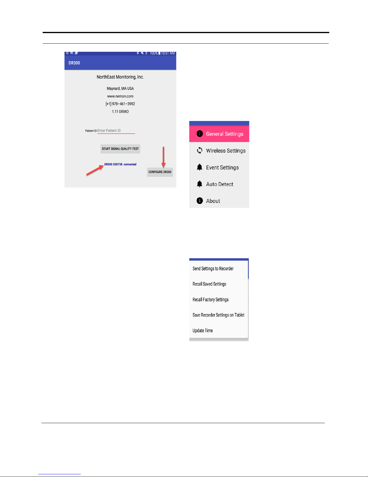
DR200/HE & DR300 Operator’s Manual DR300 Tablet App: To Update Settings on DR300 Recorder
DR300 App Splash Screen paired with DR300
Connected to DR300
To update
settings
The menus on tablet
Menu to update settings
To Update Settings on
DR300 Recorder
From the initial screen, press the CONFIGURE
DR300 button on the tablet to update the settings on
the connected recorder.
The DR300 Recorder Settings
On the left-side of the
screen, you will see a
similar menu to what
appears on the DR300
recorder. You can go to
any of the screens to see
what the current setup is
on the DR300 recorder.
Click on any of these
menus to review and/or
update the settings.
Note: Refer to Chapter
Start the DR300 Recorder
Once connected, if the recorder has Recorder Type
set to “Event”, you will see ‘START EVENT
RECORDING” in the center of the screen, and you
can press it to begin recording immediately.
recorder settings.
Update the Recorder
4 of this manual for
more information on the
If the connected recorder has Recorder Type set to
“Holter” or “Both” you will see “START SIGNAL
QUALITY TEST” in the center of the screen. At
this point you can enter the Patient ID and start the
signal quality test to see the hook-up and begin
recording. u
The Signal Quality Test
When recording Holter or Both, the Signal Quality
Test will display up to 3 channels for you to ensure
that your patient is hooked-up correctly Once you
are satisfied with the quality of the signals, click on
the arrow at the top of the tablet screen to begin
recording.
that you can use to update the Tablet:
Once the settings on the
tablet are what you
desire, click on the 3stacked dots on the
upper-right side of the
screen to get to the dropdown menu. Click on
“Send Settings to
Recorder” to update the
DR300 with what you
entered on the tablet.
The menu also includes
the following options
• Recall Saved Settings - If you previously saved
Settings on the Tablet for future use, this will
update the Tablet with those saved settings
• Recall Factory Settings - Will update the Tablet
with the Factory Settings
NorthEast Monitoring, Inc. NEMM019-Rev-O Page 24 of 35
Page 25

DR200/HE & DR300 Operator’s Manual DR300 Tablet App: Live ECG Viewing
• Save Recorder Settings on Tablet - Saves the
settings you just entered onto the Tablet for
future use
• Update Time - Will automatically update the
time and date on the recorder to match the tablet
The Wireless Settings
The Wireless Settings menu is where you can turn
Wireless On or Off. When Wireless is turned On,
the DR300 recorder will transmit saved event or
Holter through a paired NorthEast Monitoring
Gateway box.
The other items on the Wireless Settings show you
whether the recorder is paired and how your
recorder is set up for transmitting.
Note: Refer to the DR300 Gateway and Socket
Technical Manual, NEMM046, for information
on how to set up and run the Wireless feature.
Locked Recorder
Locked recorders cannot be updated or started with
the Tablet. To update settings on a locked recorder,
you will need to first unlock the recorder by going
to Settings > More > Menu Lock, and entering:
Troubleshooting
If DR300 Android App is not connecting with the
DR300 recorder that you want to configure and/or
start, you may want to try one or more of the following:
• Close and restart the DR300 Tablet App
• Make sure you have the correct recorder Serial
No.This can be found on the DR300 About
screen and in the battery compartment on the
back of the DR300.
• Make sure that only one DR300 recorder is open
to its Splash screen.
• Check to make sure that the DR300 is Paired
with the tablet. You should see the recorder
Serial No. on the Tablet’s Bluetooth screen.
• If open, close the DR300 App and restart it.
• If Paired, then turn off the Bluetooth and then
turn it back on again on the tablet. Also close
and restart the DR300 App. Once restarted,
make sure that the recorder’s Serial No. is still
visible on the Paired list.
• Restart the DR300 recorder be removing and
reinserting the battery.
• Make sure that there are no unerased events on
the recorder.
• 217 to lock the menu
• 151 to unlock the menu.
Live ECG Viewing
Additional Notes:
•
If you switch the recorder from Event to Holter
recording mode, the recorder will restart and
you may need to enter the Patient ID two times.
• If you turn of the tablet’s Bluetooth radio will
If the recorder is in Event or Holter recording mode
(not Both), at any point during recording you can
view the live ECG signal on the recorder and/or a
Tablet with the DR300 App turned on.
In order to view the live ECG signal on the
recorder, start the DR300 Tablet App, and then
press the arrows in the following order - up, down,
up, down. At that point the live ECG signal should
appear on the recorder screen and will transmit to a
tablet when available.
To stop viewing, press the record arrow in the
upper-left corner of the Tablet App. On the
recorder, press the down-arrow to stop live viewing.
NorthEast Monitoring, Inc. NEMM019-Rev-O Page 25 of 35
the DR300 Tablet software is not closed, the
software will go into a continuous mode looking
for the Bluetooth. Close the software and restart
to fix.
• The DR300 recorder will restart, if you close the
software while connected to the recorder.
Page 26

Chapter 6 -Appendices
Appendix A: Maintenance and Care of the Recorder
Clean the outside of the recorder with a damp soft cloth between uses; use water and a non-abrasive liquid soap, as required. DO NOT use any abrasive cleaners, such as acetone, on the outside
of the recorder.
Note: Always remove the battery before cleaning the recorder.
Disinfect as needed, following instructions from your infection control department. Sani-Cloth
germicidal surface wipes are recommended. Sterilization is not needed.
Do not wrap the lead wires tightly around the recorder after each use. This can damage them.
Do not pull on or stretch the lead wires when cleaning or untangling them. This can damage
them.
Do not clean the cable with harsh chemicals, such as acetone.
Do not submerge the recorder or its cables in water.
Replace the cable on a regular basis or at the first sign of damage.
At the end of their useful lives, all NorthEast Monitoring Inc. products should be disposed of
following local ordinances.
To Remove Belt Clip
If you need to remove the belt clip, you will need a long flat tool like a screw driver. In order to
remove the clip, one has to slightly pry up the end of the clip near the battery cover while pulling the clip out.
NorthEast Monitoring, Inc. NEMM019-Rev-O Page 26 of 35
Page 27

DR200/HE & DR300 Operator’s Manual Appendices: Appendix B: Batteries
Appendix B: Batteries
The recorder uses one AA-size battery. This
requirement may be fulfilled in a number of
ways. Battery types available on the market are:
• Alkaline (example: Eveready Energizer E91,
Duracell NM1500)
• Heavy Duty
• Nickel Metal Hydride (example: MAHA AA
1800 mAh, Rayovac 1600 mAh NiMH)
• Nickel Cadmium (NiCd)
Alkaline
The alkaline is the most common type of battery.
When a new, properly stored battery is used, a
recording time of 30 days can be expected in
event mode and 14 days in Holter. When the
DR300 is used in wireless mode, Holter recording can be expected to be up to 7 days before a
new battery is required.
While a recording that runs for 24 hours will in
theory use less than half the capacity of the battery, using a battery for two different patients’ 24hour recordings is not recommended. The risk is
that the "second" recording will not reach 24
hours.
The primary limitation of this battery type is that
there is only a limited ability to test the battery
before it is used. Unfortunately, at times a defective battery will appear to initially have full
capacity, but will fail well before the expected
time. The probability of this type of failure is
very small when the batteries are obtained from
the primary suppliers.
storage at a temperature below freezing will
reduce battery life.
Heavy Duty
Batteries that are labeled "Heavy Duty" vary
widely in capacity. The use of "Heavy Duty" batteries is not recommended.
Nickel Metal Hydride (NiMH)
This class of batteries is rechargeable and thus
can be used in situations where a disposable battery is not desirable. Batteries of this type come
in a range of capacities with the labeled capacity
ranging from 1100 to 1800 mAh (milliamp
hours). It is recommended that only batteries with
a rating of at least 1500 mAh be used. Lower
capacity batteries will operate the recorder for 7
days when they are new but after only a few uses
may not be able to operate for the full 7 days.
Recording time on the DR300 in wireless mode
will be significantly less than when used nonwirelessly.
Charging these batteries is the most difficult part
of their use. Only standard chargers that are specifically rated for use with NiMH batteries should
be used such as the MAHA MH-204F or Rayovac 1-Hour charger; although medicallyapproved chargers can be used, they are not necessary. Older chargers designed only for NiCd
(Nickel Cadmium) will overcharge this type of
battery and can significantly shorten battery life.
A charger that applies an excessive continuous
charge can also shorten the battery life. If in
doubt it is best not to leave the batteries on charge
for long periods of time after the charger indicates a full charge.
The best prevention available against defective
batteries is to obtain them from suppliers who do
not store them for a long time and do store them
properly. There are few requirements for storage
of alkaline batteries. They should be stored at
"room" temperatures (50-90 F) and in a dry location. There is no advantage to storing them in a
refrigerator. There is actually a significant problem with low-temperature storage. Normal refrigerators have a very high humidity inside and this
can cause a much greater reduction of life that is
gained by the lower temperatures. In addition,
NorthEast Monitoring, Inc. NEMM019-Rev-O Page 27 of 35
Unlike the older rechargeable battery types,
NiMH batteries have no real "memory." Thus
they do not need to be completely discharged or
"conditioned" to insure that they will fully
charge. Doing a complete discharge will reduce
the total life of the battery as every time the battery is discharged below about 25% capacity, the
life of the battery is shortened more than for a
normal discharge cycle.
Page 28

DR200/HE & DR300 Operator’s Manual Appendices: Appendix C: Pacemaker Detection
Most chargers for NiMH batteries depend on a
property of these batteries that causes them to heat
up when they have reached full charge. This has
two consequences. First, if the batteries are being
charged in pairs, the first battery to be fully charged
will heat up and shut down the charge cycle. This
can leave one of the batteries partially charged.
Thus it is best to keep pairs of batteries together so
they are both discharged and charged together. Secondly, if the battery is too warm for any reason, it
may shut down the charge early. For that reason the
batteries should be charged at normal room temperatures and it is often best not to cover the batteries
in any way during the charge. Even the charger's
own cover may reduce the charge. Leave the cover
open during charging.
When the battery is not being charged, it will
slowly discharge by itself. This type of battery will
lose about one percent of its charge for each day.
Most chargers will bring a partially charged battery
up to full capacity in under an hour. Batteries that
have not been used for over two weeks should be
charged before use.
If used properly, these batteries will last for 300 to
1000 recordings of 7 days each. They will still not
last forever. To control battery life, writing the date
on the battery that the batteries are first put in service can be helpful.
Nickel Cadmium
This type of battery has less capacity than the
NiMH and is not recommended. Also, disposal of
this battery can pose problems.
Battery Replacing
Insert a blunt object (for example, pen, coin or nonpointy tool) in the space between the battery and the
top edge of the recorder. Press gently to easily
remove the battery.
To insert a fresh battery into the battery compartment, be sure to orient it as indicated in the diagram
inside the compartment. The battery sits loosely in
the compartment.
Appendix C: Pacemaker
Detection
The recorder has a built-in pacemaker detection
capability. This was designed to overcome the problems inherent with the analysis of Holter recordings
from patients with pacemakers.
A pacemaker is designed to initiate cardiac conduction by stimulating a spot on the myocardium with a
pulse of 1-4 volts and a duration of typically 250 to
2,000 microseconds. When this pulse is seen at the
surface recording electrodes it is significantly attenuated. For patients with a unipolar electrode configuration, the signal at the surface may range from
under 50 to over 200 millivolts. When a bipolar
lead configuration is used, the signal is typically
much lower and is in the range of 3 to 50 millivolts.
Especially with the bipolar leads, the signal size is
dependent on the positions of the pacemaker lead
and the surface electrodes.
The amplitude of the signal being referred to here is
not the size of the "spike" commonly seen on an
ECG cart or bedside monitor. Since the duration of
the pulse is short compared to a QRS complex, normal ECG recorders will greatly attenuate the signal;
in some cases it cannot be seen at all. Also, some
ECG recorders have devices which enhance the
pace pulse to insure that it will be displayed. Only
very wide bandwidth recorders as are sometimes
used in an electro-physiology study will show the
unmodified full amplitude of the pulse.
The recorder has the wide bandwidth ECG amplifiers necessary to pass the pacemaker pulse. Since the
pulse would still be too short to be recorded in a
reliable manner at any practical sampling rate for
Holter recording, the pulse is detected by the
recorder. The time of the pulse is then digitally
stored along with the Holter ECG data. When the
data is analyzed, the pacemaker pulse is displayed
and used for the analysis.
At recording time, it is desirable to have the
recorder be as sensitive to the pacemaker pulse as
possible so pulses will not be missed. A conflicting
requirement is that there should be as few false
pacemaker detections as possible.
NorthEast Monitoring, Inc. NEMM019-Rev-O Page 28 of 35
Page 29

DR200/HE & DR300 Operator’s Manual Appendices: Appendix C: Pacemaker Detection
False pacemaker detections are primarily caused by
electrical events. Any external electrical signal that
is coupled to the patient electrodes which looks like
a pacemaker pulse will of necessity be stored by the
recorder. The most common form of electrical signal that can look like a pacemaker signal is an electrostatic discharge (ESD) or "spark." These happen
very frequently in dry weather but also occur, at a
lower rate, under humid conditions.
Fortunately most ESD spikes as seen at the patient
electrodes are of shorter duration or of lower amplitude than the real pacemaker pulses. While there is
no absolute limit to the size or duration of the ESD
pulses, the recorder ignores all pulses that are less
than 150 micro-seconds long or are less than two
millivolts in size.
As pacemakers are normally programmed to a pulse
width greater than 200 microseconds, this does not
cause a loss of detection. The requirement that the
pacemaker pulse be at least two millivolts in size is
not a common problem.
NorthEast Monitoring, Inc. NEMM019-Rev-O Page 29 of 35
Page 30
DR200/HE & DR300 Operator’s Manual Appendices: Appendix D: EMC Information
Appendix D: EMC
Information
Attention should be paid to the following
EMC information prior to installing or
using the Northeast Monitoring DR200/HE
or DR300 Digital Recorder device.
• Portable and mobile Radio Frequency
(RF) communication equipment may
interfere with the operation of the
device.
Guidance and manufacturer’s declaration – electromagnetic emissions
The Northeast Monitoring DR200/HE and DR300 Digital Recorders are intended for use in the
electromagnetic environment specified below. The customer or user of the Northeast Monitoring DR200/
HE and DR300 Digital Recorder should ensure that it is used in such an environment.
Emissions Test Compliance Electromagnetic environment –
RF emissions CISPR 11 Group 1 Northeast Monitoring DR200/HE
• The device has been tested and found
to comply with IEC/EN 60601-1-2.
• Computers, cables and accessories not
tested to 60601-1-2 may result in
increased emissions or decreased
immunity of the device.
• Verify normal operation if utilizing
the device adjacent to or stacked with
other electrical equipment.
guidance
and DR300 Digital Recorders use
RF energy only for its internal
function. Therefore, its RF
emissions are not likely to cause
any in nearby electronic
equipment.
RF emissions CISPR 11 Class B
Harmonic emissions
IEC 61000-3-2
Voltage Fluctuations/flicker
emissions IEC 61000-3-3
NorthEast Monitoring, Inc. NEMM019-Rev-O Page 30 of 35
Not applicable
Not applicable
Northeast Monitoring DR200/HE
and DR300 Digital Recorders are
suitable for use in all establishments other than domestic and
those directly connected to the
public low-voltage power supply
network that supplies buildings
used for domestic purposes.
Page 31
DR200/HE & DR300 Operator’s Manual Appendices: Appendix D: EMC Information
Guidance and manufacturer’s declaration – electromagnetic immunity
The Northeast Monitoring DR200/HE and DR300 Digital Recorders are intended for use in the
electromagnetic environment specified below. The customer or user of the recorder should ensure that
it is used in such an environment.
Immunity test IEC 60601 test level Compliance level Electromagnetic
environment – guidance
Electrostatic discharge
(ESD) IEC 61000-4-2
± 6kV contact
± 8kV air
± 6kV contact
± 8kV air
Floors should be wood,
concrete or ceramic tile.
If floors are covered with
synthetic material, the
relative humidity should be
at least 30%.
Electrical fast
transient/burst
IEC 61000-4-4
Surge
IEC 61000-4-5
± 2 kV for power
supply lines
± 1 kV for input/
output lines
± 1 kV line(s) to
line(s)
± 2 kV line(s) to earth
Not applicable.
No cables exceed 3
meters
Not applicable.
Northeast Monitoring
DR200/HE and
Mains power quality should
be that of a typical
commercial or hospital
environment.
N/A
DR300 Digital
Recorders are battery
powered.
Voltage dips, short
interruptions and
voltage variations on
power supply input
lines
IEC 61000-4-11
< 5% U
T
(>95% dip in UT)
For 0,5 cycle
40% U
T
(60% dip in UT)
Not applicable.
Northeast Monitoring
DR200/HE and
DR300 Digital
Recorders are battery
powered.
N/A
For 5 cycles
70% U
(30% dip in UT)
for 25 cycles
< 5% U
(>95% dip in UT)
for 5 s
Power frequency (50/
3 A/m 3 A/m Power frequency magnetic
60 Hz) magnetic field
IEC 61000-4-8
NOTE U
is the a.c. mains voltage prior to application of the test level.
T
NorthEast Monitoring, Inc. NEMM019-Rev-O Page 31 of 35
T
T
fields should be at levels
characteristic of a typical
location in a typical
commercial or hospital
environment.
Page 32
DR200/HE & DR300 Operator’s Manual Appendices: Appendix D: EMC Information
Guidance and manufacturer’s declaration – electromagnetic immunity
The Northeast Monitoring DR200/HE and DR300 Digital Recorders are intended for use in the
electromagnetic environment specified below. The customer or user of the recorder should ensure that it is
used in such an environment.
Immunity test IEC 60601 test
level
Compliance
level
Electromagnetic environment – guidance
Portable and mobile communications equipment
should be used no closer to any part of the
Northeast Monitoring DR200/HE and DR300
Digital Recorder, including cables, than the
recommended separation distance calculated
from the equation applicable to the frequency of
the transmitter.
Recommended separation distance
Conducted RF
IEC 61000-4-6
Radiated RF
IEC 61000-4-3
3 Vrms
150 kHz to 80 MHz
3 V/m
80 MHz to 2,5 GHz
3 V
3 V/m
d = 1.2
d = 1.2
d = 2.3
P
P 80 MHz to 800 MHz
P 800 MHz to 2.5 GHz
Where P is the maximum output power rating of
the transmitter in watts (W) according to the
transmitter manufacturer and d is the
recommended separation distance in metres (m).
Field strengths from fixed RF transmitters, as
determined by an electromagnetic site survey,
should be less than the compliance level in each
frequency range.
b
Interference may occur in the vicinity of
equipment marked with the following symbol:
NOTE 1: At 80 MHz and 800 MHz, the higher frequency range applies
NOTE 2: These guidelines may not apply in all situations. Electromagnetic propagation is affected by
absorption and reflection from structures, objects and people.
a Field strengths from fixed transmitters, such as base stations for radio (cellular/cordless)
telephones and land mobile radios, amateur radio, AM and FM radio broadcast cannot be
predicted theoretically with accuracy. To assess the electromagnetic environment due to fixed RF
transmitters, an electromagnetic site survey should be considered. If the measured field strength
in the location in which the recorder is used exceeds the applicable RF compliance level above,
the recorder should be observed to verify normal operation. If abnormal performance is observed,
additional measures may be necessary, such as re-orienting or recorder
b Over frequency range 150 KHz to 80 MHz, field strengths should be less than 3 V/m.
a
NorthEast Monitoring, Inc. NEMM019-Rev-O Page 32 of 35
Page 33
DR200/HE & DR300 Operator’s Manual Appendices: Appendix D: EMC Information
Recommended separation distances between portable and mobile RF communications equipment
and the Northeast Monitoring DR200/HE and DR300 Digital Recorder
The Northeast Monitoring DR200/HE and DR300 Digital Recorders are intended for use in the
electromagnetic environment in which radiated RF disturbances are controlled. The customer of the user
of the recorder can help prevent electromagnetic interference by maintaining a minimum distance between
portable and mobile RF communications equipment (transmitters) and the recorder as recommended
below, according to the maximum output power of the communications equipment.
Rated
maximum
output power of
transmitter
150 KHz to 80 MHz
Separation distance according to frequency of transmitter
m
80 MHz to 800 MHz
d = 1.2
P
d = 1.2 P
800 MHz to 2.5 GHz
d = 2.3 P
W
0.01 0.12 0.12 0.23
0.1 0.38 0.38 0.73
1 1.2 1.2 2.3
10 3.8 3.8 7.3
100 12 12 23
For transmitters rated at a maximum output power not listed above, the recommended separation distance
d in metres (m) can be estimated using the equation to the frequency of the transmitter, where P is the
maximum output power rating of the transmitter in watts (W) according to the transmitter manufacturer.
NOTE 1: At 80 MHz and 800 MHz, the separation distance for the higher frequency range applies.
NOTE 2: These guidelines may not apply in all situations. Electromagnetic propagation is affected by
absorption and reflection from structures, objects and people.
NorthEast Monitoring, Inc. NEMM019-Rev-O Page 33 of 35
Page 34

DR200/HE & DR300 Operator’s Manual Appendices: Appendix E: Extraction of ECG data on 3-channel
Appendix E: Extraction of
ECG data on 3-channel
It is possible to retrieve the raw ECG files from the
Holter files. For all 3 channel data the process
results in three files, one for each channel. Each
file is then in the form of a binary file consisting of
16bit words (little endian) with each word representing one sample. The sampling is at 180 samples per second. The data is scaled so that the least
significant bit has a value of 12.5 uv. If a pacemaker pulse was detected, the sample at the time
of detection will be replaced by the value 0x8000.
To generate these files, first analyze the data (actually the flash.dat) from the recorder using any
compatible version of the LX Analysis program.
At the completion of this there will be a file "datacard.dat" in the patient directory. The full path is
by default:
c:\nm\pat\xx\datacard.dat
where xx is the number of the patient dataset.
This can be seen in the "No. and Directory"
columns of the "File->open/new" display.
Then, change the directory to c:\nm\bin and on a
single command line, run the following command
using the following 5 arguments:
unpackc d1 f1 f2 f3 0
• where d1 is the path to the source datacard file,
for example,
d1= c:\nm\pat\xx\datacard.dat
• f1, f2 and f3 are the resultant binary destina-
tion files, for example:
f1 = c:\nm\pat\xx\flashc0.dat
f2 = c:\nm\pat\xx\flashc1.dat
f3 = c:\nm\pat\xx\flashc2.dat
Appendix F: Accessories
NEMCA158 - 2-Lead Patient Cable,
Adult Small - 24”
NEMCA135 - 2-Lead Patient Cable,
Adult Medium - 30”
NEMCA145 - 3-Lead Patient Cable,
Adult Small - 24”
NEMCA146 - 3-Lead Patient Cable,
Adult Medium - 30”
NEMCA150 - 3-Lead Patient Cable,
Adult Large - 38”
NEMCA144 - 5-Lead Patient Cable,
Adult Small - 24”
NEMCA134 - 5-Lead Patient Cable,
Adult Medium - 30”
NEMCA149 - 5-Lead Patient Cable,
Adult Large - 38”
NEMCA133 - 7-Lead Patient Cable,
Adult Medium 30”
NEMH112 - Battery Door
NEMH116 - Belt Clip
NEMH187 - Recorder Pouch and Straps
NEMP00387 - Memory - SD Card
The result will be the three files in the patient
directory xx described previously. The files are
flashc0.dat flashc1.dat and flashc2.dat which are
for channel 1,2 and 3 respectively. If desired, the
destination paths for this command can be any
other path but spaces are not allowed in the path or
file name.
NorthEast Monitoring, Inc. NEMM019-Rev-O Page 34 of 35
Page 35

DR200/HE & DR300 Operator’s Manual Appendices: Appendix G: Test Issues
Appendix G: Test Issues
Bug
Problem Version
No.
1054 Find Gateway does not work after the
recorder has been left on for a while.
1486 The DR300 MCOT Parameter check value
does not lock when the recorder is locked.
1503 The Holter recorder should only be set to
Hi Resolution On, or 3-channel. For
Holter, 1- and 2-channel do not work in
this release. This also affects Both mode
recording.
1504 DR300 wireless may malfunction when
the battery is low
Impact on device
Found
safety or
effectiveness
4.42 There is no impact on
device performance.
4.46 There is no impact on
device performance as
MCOT is not yet
enabled.
4.46 If the recorder is set to
record Holter in 1 or 2channel, it will not work.
4.46 The recorder may stop
sending wireless
transmits for the short
term, but a new battery
will fix the problem.
Plan to correct, if
applicable
There is no plan to
correct.
This will be
corrected in the
next release with
MCOT.
This will be
corrected in the
next release.
There is no way to
fix this, but we
will improve the
Low Battery
message to be
more sensitive
when Wireless is
turned on.
NorthEast Monitoring, Inc. NEMM019-Rev-O Page 35 of 35
 Loading...