

North Bayou FC35 Instruction Manual
FC35
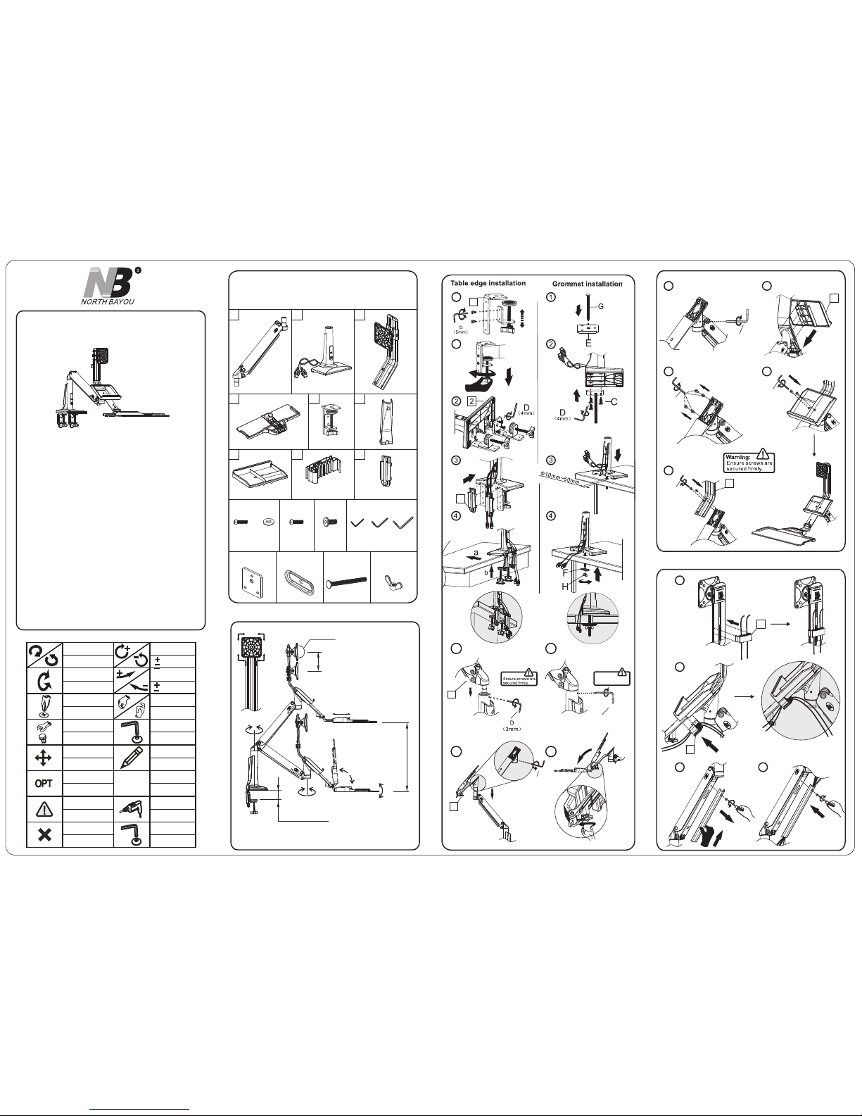
Sit- St and Works ta tion De sk top
Inst ru ction M an ual
Fit s Most Di splay s Size: 22 "~3 2"
Max L oad 6.6 ~: 19. 8Ib s (3~9k g)
VES A:75×75 ,100×10 0mm
Severe personal injury and property damage can result from improper installation or assembly.
Read the following warning carefully before beginning.
● Products must be installed by professional or installer.
● If you do not understand the instructions or have any concerns or questions, please
contact a qualified local installer.
● Do not install or assemble if the product or hardware is damaged or missing, if you
require replacement parts, please contact you local distributor for assistance.
● This product fits most 22"-32" LCD / monitor; maximum weight of LCD / monitor:
9kg / 19.8lbs.
● Installer-friendly and straight forward.
● For safe installation, the desk you are mounting to must support minimum 3 times the
weight of the total load (the mount, the monitor and all accessories weight).
● Do not use this product for other than the original designed.
● This product contain moving parts, please use with caution.
● When installing monitor, please do not damage electrical wiring or power source.
● Installation and routing of monitor cables on the monitor bracket must comply with
electro-technical regulations.
● Importantly, mains- and data-cables must be secured against twisting and squeezing or
shearing.
● The manufacturer will bear no responsibility to the desk of mounting, or incidental
or consequential damages arising thereof.
● The manufacturer disclaims any liability for the modifications, improper installation, or
installation over the specified weight range. The manufacturer will not be liable for any
damages arising out of the use of , or inability to use, the product.
● This product is designed for indoor used only, use of this product outdoor could lead to
product failer and severe personal injury.
▲ This product contains a high pressure gas spring, fire and percussion are prohibited. Also
it is strictly prohibited to dismantle without professionals. Please return to the manufacturer
or hand over to professional agencies if the product is abandoned. In order to ensure
the performance of gas spring, full direction adjustment of the product arm is recommended
several times per month.
We reserve the right to modify or alter instructions. No modification or alteration without formal notice.
Symbols
Tightening Direction
By Hand
Adjustment
loos ening D irect ion
Hex Wrench
Phillips Screwdriver
Pencil
Optional
Warning
Reminder
Open-End Wrench
Hand Drill
Star Wrench
拧紧方向
用手
调整
拧 方 向松
六角扳手
螺丝起子
铅笔
可选
警告
提示
开口扳手
手电钻
安全扳手
Remove
移开
定点恒力 加大
定点恒力 减小
+- :Torqu e incre ased
:Torqu e reduc ed
+- :Torqu e incre ased
:Torqu e reduc ed
拧紧方向
拧 方 向松
Tightening Direction
loos ening D irect ion
NO TE
定点恒力 加大
定点恒力 减小
A、Full adjustment after installation
FC
35
Part List
E GF
2x
1 2 3
4
6
8
9
2x
7
(M5x 12)
B
4x
A C
6x
(M6x 15)
(3MM )
(4MM )
(5MM )
D
H
400 10801 01 A1
C、Pow er and di splay l ines in stall ation
1
2
3
4
a
D
(5mm)
11
9
(5mm)
D
D
(3mm)
10
8
(5mm)
D
3
7
8
8
b
7
(M4x1 2)
4x 4x
(∅10x 4.5x1 .0)∅
360°
FC
35
Max L oad:6 .6~19 .8lbs (3~9k g)
0~3. 7"(0~ 95mm)
180°
95
°
180°
± °12
0~ 0~3.9 "( 100 mm)
0~2 .4"(0 ~60mm )
+12°/ -15°
0~ 0~18. 9"( 48 0mm)
2x
B、Des kmoun t insta llati on
Tighte n set scr ew
flush w ith sur face.
D
(3mm)
6a
4
5
1a
0-
9
5mm
1b
1
5
9
D
(3mm)
6b
5b
5a

L、Key board t ray fol d up adju stmen t
www.n bavmo unt.c om
TEL: 8 6-512 -5797 1777
FAX: 86 -512- 57970 776
Cloc kwise t o reduc e
tens ion(c arry le ss weig ht)
Anti -cloc kwise t o incre ase
tens ion(c arry mo re weig ht)
War nin g!
Add:58, South of Xinxing Road,
Economic Development Zone.
Kunshan City, Jiangsu Province, China.
215333.
Do no t adjus t tensi on with out put ting on d ispla y.
1.E nsure d ispla y has bee n put ont o mount .
2.R ead you r displ ay pack aging o r manua l to find
out d ispla y net wei ght.
3.E nsure d ispla y net wei ght bet ween 6. 6~19. 8lbs
(3~ 9kg).
TENS IO N ADJ USTME NT
AFTE R IN STALL ED
9
5°
b
1 2
Not e:
The pr e-s re fo rce i s
at th e med ium.
Warning:
Ens ure scr ews are
sec ured fi rmly.
D、Dis play in stall ation
VESA:75x7 5m m, 10 0x 10 0m m
75x
75
mm
1
0
0
x
1
0
0
m
m
6
5
G、Dis play he ight ad justm ent
E、Rot ation R estri ction
F、Torque adjustment
Non -prop er usag e direc tions Pro per usa ge dire ction s
J、Key board t ray ext ends ad justm ent
360°
-15°
+12°
H、Til t angle a djust ment
I、Dis play ro tatio n
D
( )5mm
K、Key board t ray ang le adju stmen t
Inclined adjustment Declind adjustment
Dec lind ad justm ent:
Inc lined a djust ment:
①Turn s crew an ti-cl ockwi se dire ction u sing 3m m Allen ke y D to
rel ease. ②T urn scr ew cloc kwise direc tion us ing 3mm A llen ke y
D t o ti lt u prigh t ang le.③ Turn screw cloc kwise dir ectio n usi ng
3mm Al len to ti ghten a nd secu re set an gle.
①Turn s crew an ti-cl ockwi se dire ction u sing 3m m Allen ke y D to
til t d own sid e a ngle.② Tu rn scre w c lockw ise dir ectio n u sing
3mm Al len to ti ghten a nd secu re set an gle.
1
-12°
+
1
2°
①
③
②
D
(3mm)
-12°
+
12
°
D
(3mm)
①
②
0
~6
0mm
2 3
6
a
b
"+ ":Torque increase direction shown fig-1
"- " Torque decrease direction shown fig-2:
fig -1
fig -2
D
( )5mm
Notes:Ensure display weight is within load range.
If di splay a nd keyb oard tr ay can be h overe d at any he ight af ter
dis play in stall ed. No ad justm ent nee ded.
1.
If displ ay an d key board tray rise up a utoma tical ly af ter d ispla y
ins talle d, a djust the fol lowin g: O ne m an h and press dow n t he
scr een,t he other w ind set sc rew at th e b ottom o f upper a rm
at joi nt to ' – ' dir ectio n to reduc e torqu e by usin g F, 5mm.
All en key as s hown in F ig-1 an d Fig-2 u ntil di splay a nd keyb oard
tra y can be ho vered a t any poi nt of pos ition s.
2.
If d is pl ay and k ey boa rd t ra y a t the l owe st p os it ion a ft er
ins talla tion, r epeat # 2 proce dures b ut wind ing set s crews t o ' + '
dir ectio n to incr ease to rque as F ig-1 an d Fig- 2 until d ispla y and
key board t ray can b e hover ed at any p oint of p ositi ons.
3.
A/B
Need 2 m en. man A and m an B.
Once s et, man A pus h knob do wn to
lock .
Man A, on e hand ho lds arm d own.
Anot her han d finge rs push a nd hold
knob u p to rele ase.
Man B us e both ha nds hol d displ ay 2
side s and adj ust to de sire he ight.
0~1 00mm
1.1.
2.
3.
4.
5.
 Loading...