

Page 1
8809528 06/12
9 GALLON 6.5HP TWIN TANK
GAS AIR COMPRESSOR
DO NOT RETURN TO
STORE. Please CALL
800-348-5004 for parts
and service.
CALIFORNIA PROPOSITION 65
WARNING: You can create dust
when you cut, sand, drill or grind
materials such as wood, paint,
metal, concrete, cement, or other
masonry. This dust often
contains chemicals known to
cause cancer, birth defects, or
other reproductive harm. Wear
protective gear.
WARNING: This product or its
power cord may contain
chemicals, including lead,
known to the State of California
to cause cancer and birth
defects or other reproductive
harm. Wash hands after
handling.
Important!
When using equipment, a few
safety precautions must be
observed to avoid injuries and
damage. Please read the complete
operating manual with due care.
Keep this manual in a safe place,
so that the information
is available at all times. If you
give the equipment to any other
person, give them these
operating instructions as well.
We accept no liability for
damage or accidents which
arise due to non-observance of
these instructions and the
safety information herein.
SPECIFICATIONS
Engine: 6.5 HP OHV
Tank capacity: 9 gallons
Pressure: 115 PSI
Speed: 1150 RPMs
12 CFM @ 90 PSI
CAUTION:
FOR YOUR OWN SAFETY,
READ INSTRUCTION
MANUAL COMPLETELY AND
CAREFULLY BEFORE
OPERATING THIS GAS
COMPRESSOR.
Any failures made in
following the safety
regulations and instructions
may result in an electric
shock, fire and/or serious
injury.
SAFETY INSTRUCTIONS
1) Only persons who are
familiar with these
instructions and warnings
should operate this
compressor.
2) Do not allow children in the
work area and keep visitors
back away from equipment.
3) Use safety glasses and
hearing protection when you
are operating this unit.
4) Do not stand on the unit or
use it as a handhold.
5) Before each use, inspect
the compressor for signs of
damage, deterioration,
weakness or leakage. Repair
or replace damaged items
before use.
6) Check the fasteners at
frequent intervals to ensure
proper tightness.
7) Motors, electrical
equipment and their
Model: 9528, 7295
For customer service, call 1-800-348-5004 or email [email protected]
Page 2

2
controls can cause electrical
arcs that could ignite flammable
gas or vapors. Do not store any
flammable liquids or gases near
the compressor.
8) Carbon monoxide is
produced when operating this
unit and can cause severe
nausea, fainting or death. Do
not operate this unit in a poorly
ventilated area or while inside a
closed building.
9) Never operate a compressor
without a belt guard. It is
possible for a compressor to
start without warning. Personal
injury or property damage could
occur from coming in contact
with moving parts.
10) Do not wear loose clothing
or jewelry. Keep long hair pulled
back.
11) Compressor parts may be
hot even though the unit may be
stopped.
12) Keep fingers and
appendages away from the
compressor while it is running.
Fast moving and hot parts can
cause injury and/or burns.
13) If any of the equipment
starts to vibrate abnormally,
stop the engine/motor and
inspect the unit immediately for
the cause.
20) Make sure to drain the tank
regularly and inspect it
periodically for unsafe conditions
such as rust and corrosion.
21) Release air slowly when
draining moisture or
depressurizing the air
compressor system. Fast moving
air will stir up dust and debris,
which may be harmful.
22) Stop the engine and make
sure all moving parts have
stopped when leaving the work
area, before cleaning, making
repairs or inspecting the unit.
23) Allow the engine to cool
before storing the unit.
24) Do not spray flammable
materials within the vicinity of an
open flame or near ignition
sources, including the
compressor unit.
25) Do not smoke when spraying
paint, insecticides or other
flammable substances.
26) Use a facemask when
spraying. Spray in a well
ventilated area to prevent health
and fire hazards.
27) Do not direct any sprayed
materials at the compressor.
Keep the compressor as far
away as possible from the
spraying area to minimize the
accumulation on the compressor.
14) Never refuel a running or
hot engine. Fuel is explosive
and can cause fires and severe
burns. Avoid overfilling the fuel
tank.
15) Check the fuel level before
starting the engine. Do not fill
the gas tank while indoors.
Wipe off any spilled gas from
the unit before starting the
engine.
16) Gasoline vapors are highly
flammable. Only refill the tank
outdoors or in a well-ventilated
area. Do not store, use or allow
spills near an open flame or
heat devices that utilize a pilot
light or could create a spark. If
gasoline is spilt, move the unit
away from the spill and avoid
creating any sparks until the
vapors have evaporated.
17) In order to reduce the fire
hazard, keep the engine and
motor exterior free of oil,
solvents or excessive grease.
18) Never remove or attempt to
adjust the safety valve. Keep
the safety valve free from paint
and other accumulations.
19) Never attempt to repair or
modify a tank. Welding, drilling
or any other modifications made
will weaken the tank and result
in damage by rupture or
explosion. Always replace worn
or damaged tanks.
Page 3
3
OPERATION
Start Up
1) Add 87 octane (or higher)
unleaded gasoline to the engine
gas tank and SAE 10W-30 oil to
the engine oil tank. A different
viscosity oil may be required if
the compressor is operated at
different ambient temperatures.
Please refer to the engine
manual for more details.
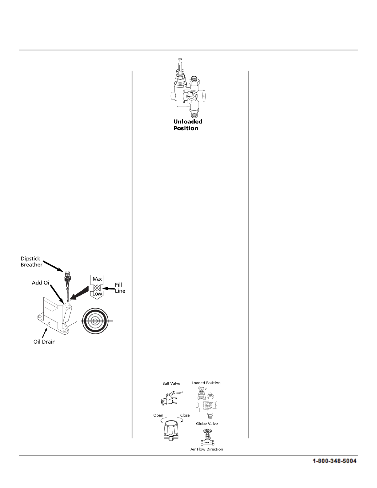
2) Remove the compressor
dipstick breather and fill the
pump to the proper oil level.
Use a single viscosity, ISO 100
(SAE 30) non-detergent
compressor oil. Do not use a
multi viscosity oil such as 10W-
30.
3) Turn the outlet valve or
regulator knob counterclockwise
to open the airflow.
4) Turn the manual unloader
lever to a vertical position in
order to allow the compressor
pump to run without
compressing air.
Starting A Gasoline Engine
1) Move the choke lever to the
CHOKE position and turn the
stop lever towards the ON
position.
2) Pull the start grip lightly until
resistance is felt, then pull on the
start grip briskly to start the
engine.
3) As the engine begins to warm
up, gradually move the choke
lever to the OPEN position.
4) Run the compressor at an
unloaded speed for
approximately 30 minutes in
order to break in the pump.
5) After approximately 30
minutes of run time, move the
unloader lever down to the
loaded position and turn the
regulator knob clockwise. The
compressor will begin to pump
air into the tank at this time.
When the maximum tank
pressure is achieved, the
compressor automatically
unloads, which brings the
engine to idle. The engine
remains at the idle state until the
pressure in the tank falls to a
preset level. The engine will then
accelerate and the compressor
will pump additional air into the
tank.
MAINTENANCE
WARNING: Release all
pressure from the system
before attempting to perform
any maintenance, relocate,
service or install the unit.
Check the air filter, oil level and
gasoline level before each use in
order to maintain efficient
operation of the unit.
The ASME safety valve should
be checked before each use. Pull
the ring on the safety valve and
allow the ring to snap back into
its normal position. This valve
automatically releases air if the
tank pressure exceeds a preset
maximum. If air leaks after the
ring has been released, or if the
valve is stuck and cannot be
actuated by the ring, the ASME
safety valve must be replaced.
Do not attempt to tamper with
the ASME safety valve.
With the engine OFF, clean any
debris from the engine, flywheel,
tank, air lines and pump cooling
fins.
Never attempt to repair or
Page 4
4
modify the tank. Welding,
drilling or any other
modifications will weaken the
tank and could result in
damage from rupture or
explosion. Always replace
worn, cracked or damaged
tanks as soon as possible.
Drain liquid from the tank at
the end of each use.
Drive Belt
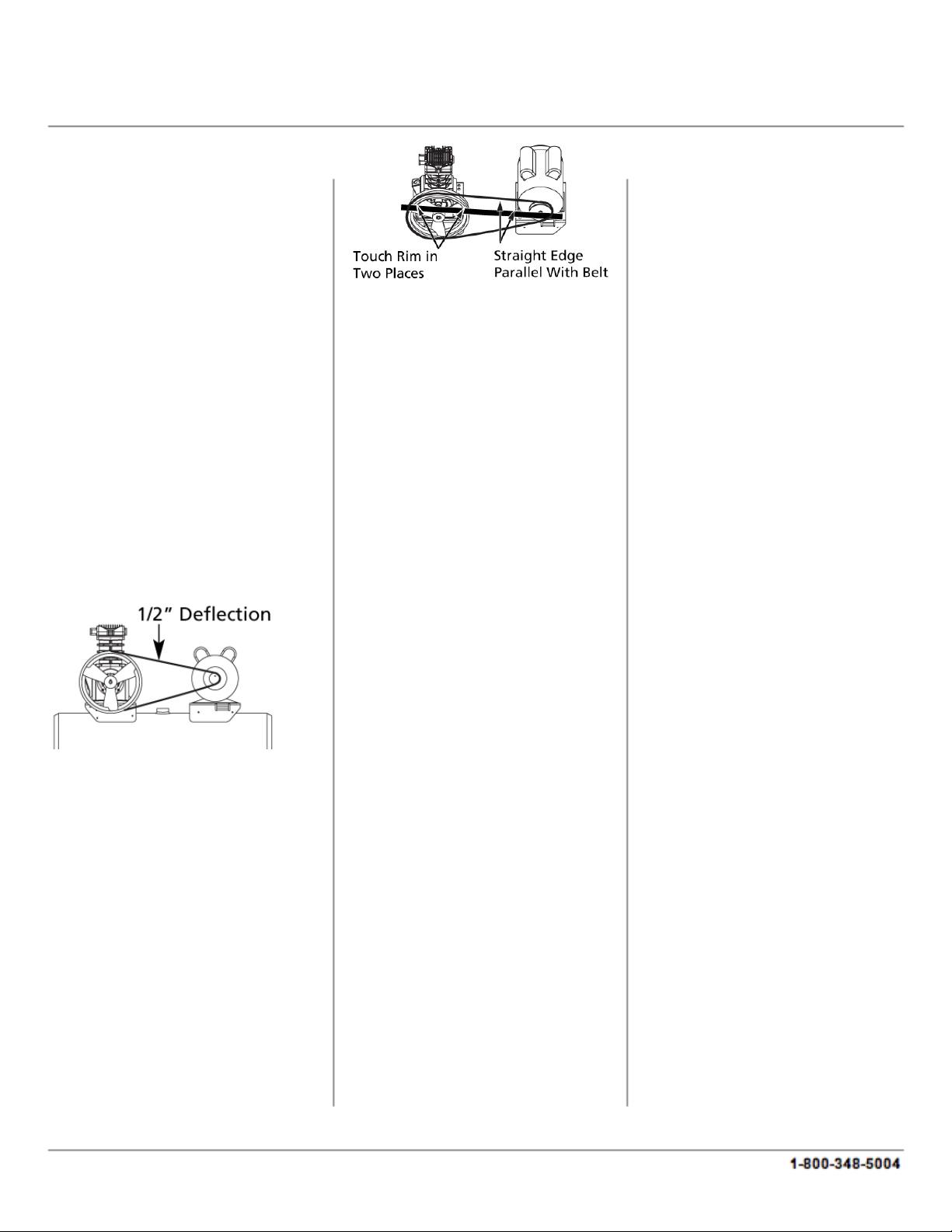
Belts will stretch as a result of
normal use. When they are
properly adjusted, the belt
deflects about ½ inch with 5
pounds of pressure applied
midway between the engine
pulley and pump.
To adjust the drive belt tension:
1) Remove the belt guard and
loosen the engine brace.
2) Loosen the four fasteners
that are holding the motor to the
base plate.
3) Shift the motor in the proper
direction. The belt must be
properly aligned when this
adjustment is made.
4) To align the belt, lay a
straight edge against the face of
the flywheel, touching the rim at
two places.
5) Adjust the flywheel or motor
pulley so that the belt runs
parallel to the straight edge.
6) Use a gear puller to move the
pulley on the shaft and to tighten
the fasteners.
7) Adjust the brace and then
tighten the fasteners, braces and
reinstall the belt guard.
Storage
1) When the unit is not in use,
the air hose and compressor
should be stored in a cool, dry
location.
2) Tanks should be drained of
moisture. The hose should be
disconnected and hung with the
open ends down to allow any
moisture to drain.
Maintenance Schedule
Check Oil: Daily
Drain Tank: Daily
Check Air Filter: Weekly
Check Safety Valve: Weekly
Blow Dirt From Inside Motor:
Weekly
Check Belt Tightness: Monthly
Change Oil: Every 3 Months
Page 5
Problem
Possible Cause Possible Solution
Low oil shutdown Fill engine with adequate amount of oil
Cold engine Choke engine to start
No fuel
Add gas to engine. Make sure fuel shutoff
valve is open.
Engine does not turn ON Place ON/OFF switch in the ON position
Spark plug wire not
attached
Attach spark plug wire to spark plug
Air leaks in discharge
piping
Check tubing connections. Tighten joints or
replace as required.
Compressor components
are leaky, broken or
loose
Inspect the components and clear or replace
as required
Flywheel or motor pulley
is loose, excessive end
play in motor shaft or
loose drive belts
Check flywheel, motor pulley or the
crankshaft drive belt tension/alignment.
Replace or repair as required
Clogged or dirty inlet
and/or discharge line
Clean or replace
Defective safety/relief
valve
Replace
Pressure switch unloader
leaks or does not work
Realign stem or replace
Leaking, broken or worn
inlet unloader parts at
check valve
Inspect parts and replace as requried
Compressor viscosity is
too high for the ambient
temperature
Drain the existing lubricant and refill the
tank with the proper lubricant
Belt tension is too tight
or sheaves are not
aligned
Check the tension and/or alignment
Flywheel or motor pulley
is loose, excessive end
play in motor shaft or
loose drive belts
Check flywheel, motor pulley or the
crankshaft drive belt tension/alignment.
Replace or repair as required
Leaking check valve or
check valve seat is blown
out
Replace check valve
High interstage
pressure
High pressure inlet valve
leaking
Inspect, clean or repair as required
Low interstage
pressure
Low pressure inlet valve
leaking
Inspect, clean or repair as required
Engine does not
start
Air delivery drops
off
Compressor does
not come up to
speed
Page 6
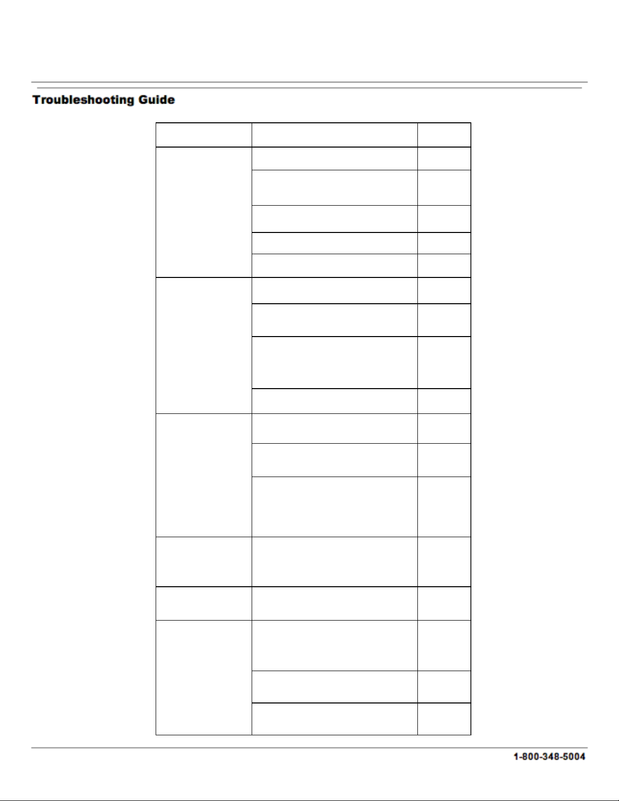
Problem
Possible Cause
Possible
Solution
Compressor viscosity is too high for the
ambient temperature
Drain the
existing
Belt tension is too tight or sheaves are not
aligned
Check the
tension
and/or
alignment
Flywheel or motor pulley is loose, excessive
end play in motor shaft or loose drive belts
Check
flywheel,
motor pulley
Leaking check valve or check valve seat is
blown out
Replace
check valve
Clogged or dirty inlet and/or discharge line
Clean or
replace
Air leaks in discharge piping
Check tubing
connections.
Tighten joins
Clogged or dirty inlet and/or discharge line
Clean or
replace
Pressure switch unloader leaks or does not
work
Realign stem
or replace
Leaking, broken or worn inlet unloader parts
at check valve
Inspect parts
and replace
Pressure switch unloader leaks or does not
work
Realign stem
or replace
Excessive condensation in receiver tank
Drain receiver
tank
Light duty cycle
Increase duty
cycle
Moisture in crankcase,
milky substance in oil
Detergent lubricant in crankcase
Replace with
proper
lubricant
Oil in discharge air Lubricant level too high
Drain excess
lubricant
Clogged or dirty inlet and/or discharge line
Clean or
replace
Defective safety/relief valve Replace
Pressure switch unloader leaks or does not
work
Realign stem
or replace
Safety/relief valve pops
Compressor is slow to
come up to speed
Compressor will not
unload cycle or will not
unload when stopped
Excessive starting or
stopping
Page 7

7
North American Tool Industries (NATI) makes every effort to ensure that this product meets high quality
and durability standards. NATI warrants to the original retail consumer a 1-year limited warranty from
the date the product was purchased at retail and each product is free from defects in materials.
Warranty does not apply to defects due directly or indirectly to misuse, abuse, negligence or accidents,
repairs or alterations, or a lack of maintenance. This product is intended for personal use. The warranty
will be voided if used in commercial, rental, or industrial applications. NATI shall in no event be liable for
death, injuries to persons or property, or for incidental, special or consequential damages arising from
the use of our products. To receive service under warranty, the original manufacturer part must be
returned for examination by an authorized service center. Shipping and handling charges may apply. If
a defect is found, NATI will either repair or replace the product at its discretion.
DO NOT RETURN TO STORE
For Customer Service:
Email [email protected] or Call 1-800-348-5004
Page 8
8909528 12/13
9 GALLON 6.5HP TWIN TANK
GAS AIR COMPRESSOR
8
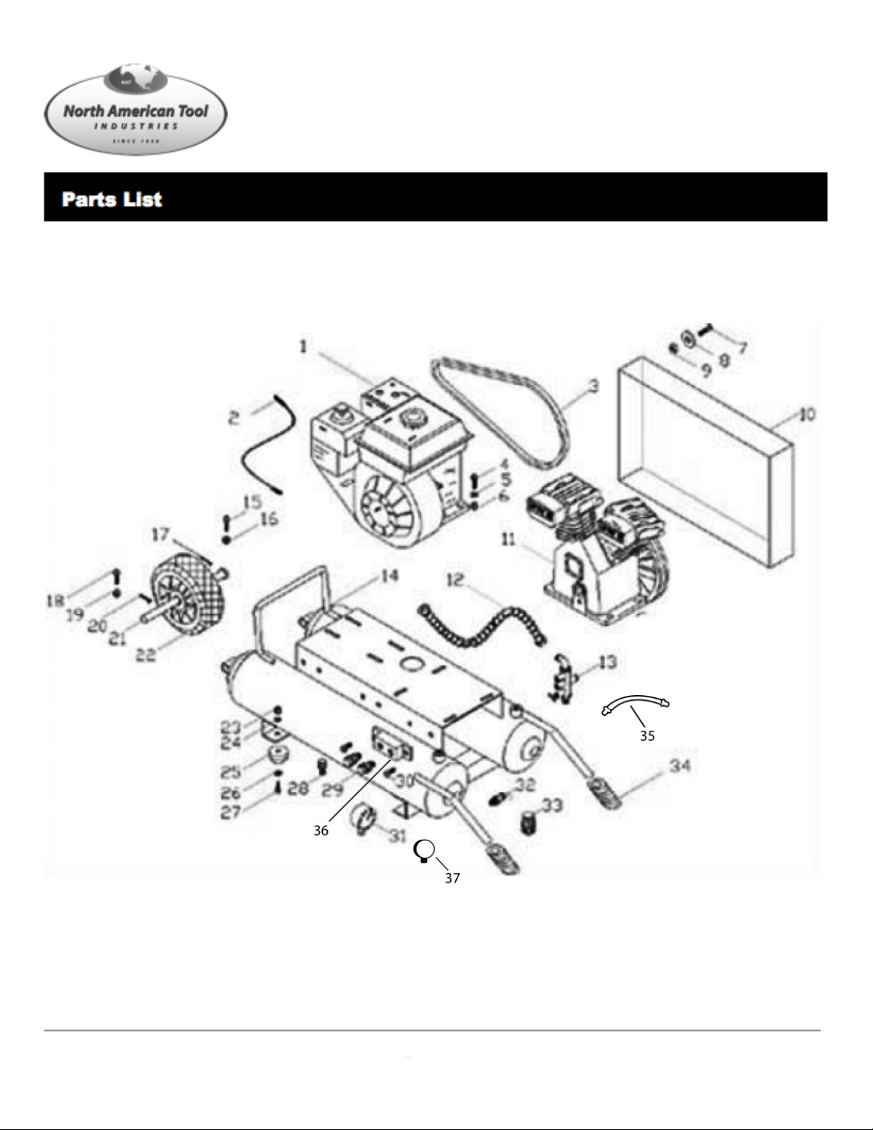
Exploded View
For customer service, call 1-800-348-5004 or email [email protected]
Page 9
9
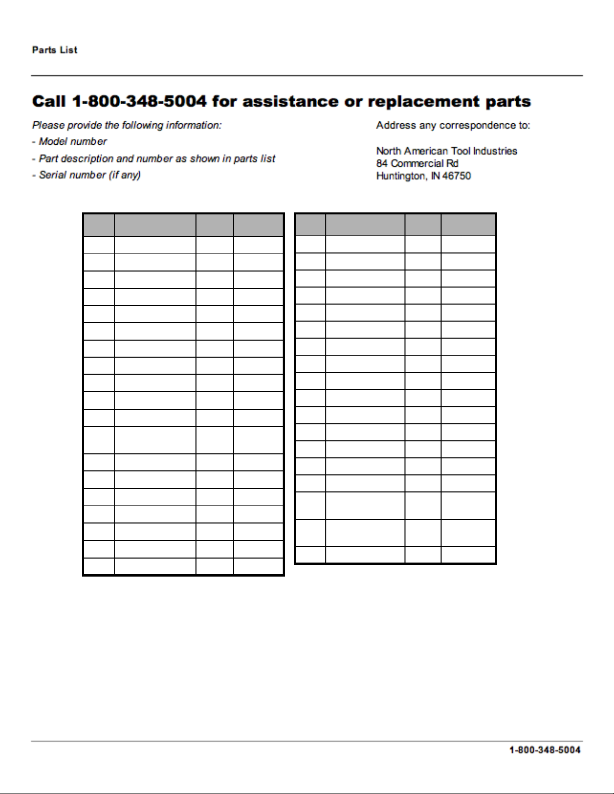
4Spring Washer19
1Tank14
1Bolt15
4Spring Washer16
4Cotter Pin17
4Bolt18
425261Comb Valve13
42525
42524
42530
42523
SKU#
1Pump11
1Discharge Tube12
1Belt Guard10
4Nut9
4Washer8
4Bolt7
4Nut6
4Spring Washer5
4Bolt4
1Bolt3
1Cable2
1Engine1
QTYDescriptionNo.
409422Drain Valve28
425292Quick Connect29
2Bolt30
425311Pressure Gauge31
425321Safety Valve32
425331Regulator33
1Grip34
425341
Plastic Supply
Line
35
1
Quick Connect
Manifold
36
409331Pressure Gauge37
4Washer26
4Bolt27
385274Bumper25
42528
42527
SKU#
4Nut23
4Spring Washer24
1Tire22
4Axle21
4Cotter Pin20
QTYDescriptionNo.
Page 10
Page 11
11
42551
42550
42549
42548
42547
42546
42545
42544
42543
42542
42541
42540
42539
42538
42537
41020
41002
42536
42535
SKU#
Bolt24
Oil Needle23
Connector Rod22
Piston Pin21
Piston20
Retaining Ring in Hole19
Oil Ring18
Compressor Ring17
Cylinder Down Washer16
Cylinder15
Split Washer14
Bolt13
Cylinder Up Washer12
Valve Plate11
Valve Seat10
Aluminum Washer9
Head Washer8
Aluminum Pipe7
Elbow6
Exhaust Elbow5
Filter4
Head3
Split Washer2
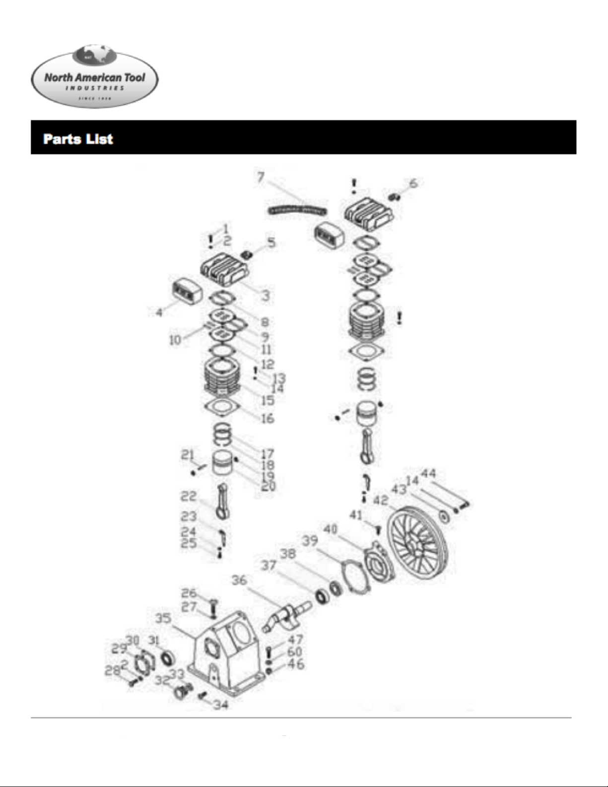
Bolt1
DescriptionNo.
42554
42553
42552
SKU#
Bolt47
M8 Nut46
Split Washer45
Bolt44
Split Washer43
Pulley42
Bolt41
Crankcase Back Cover40
Crankcase Back
Washer
39
O-Ring38
Bearing37
Crank Shaft36
Crankcase35
Oil Drain Plug34
O-Ring33
Oil Window32
Bearing31
Crankcase Washer30
Crankcase Cover29
Bolt28
Split Washer27
Bolt26
Split Washer25
DescriptionNo.
 Loading...