

Page 1

RETURN TO SERVICE PROCEDURE TABLE OF CONTENTS
RETURN TO CD-ROM TABLE OF CONTENTS
Field
Service
Procedure
Part Number: SP00189
Date: 12 June 2002
© 2002 Draeger Medical, Inc.
Rev: C
D-TEC Desflurane Vaporizer Installation
on Machines With
Removable Vaporizer Mounting Systems
Page 2

RETURN TO SERVICE PROCEDURE TABLE OF CONTENTS
RETURN TO CD-ROM TABLE OF CONTENTS
Page 3

RETURN TO SERVICE PROCEDURE TABLE OF CONTENTS
RETURN TO CD-ROM TABLE OF CONTENTS
D-TEC Desflurane Vaporizer Installation on
Machines with Removable Vaporizer Mounting Systems
Installation Procedure
NOTE: This procedure only applies to installation of D-Tec Desflurane vaporizer
on Narkomed 6000, Narkomed M, Narkomed GS Euro, Julian, Fabius GS and
Fabius machines with removable vaporizer mounting systems. Refer to Field
Service Procedure SP00091 for other desflurane vaporizer installations.
¡¡¡¡WARNING: Do not install a D-Tec vaporizer in the right hand position of a
Narkomed 6000 as this will result in an incorrect fit and may cause leaks in the
fresh gas delivery system.
¡¡¡¡WARNING: Do not install a D-Tec vaporizer on a Narkomed Mobile without the
correct vaporizer support block as this will result in an incorrect fit and may
cause leaks in the fresh gas delivery system. Refer to this procedure to verify
correct vaporizer support block prior to D-Tec vaporizer mounting.
¡¡¡¡WARNING: The O-rings supplied with this vaporizer are incompatible for use on
the Narkomed 6000, Narkomed GS Euro, Narkomed M, Fabius GS or the USA
manufactured Fabius. These systems shall only use O-RING #113 (NITRILE) P/N
4115864.
NOTE:Proceed to Section 2.0 if you are not
removing an existing vaporizer.
1.0 Vaporizer Draining, Drying and
Removal Procedure:
¡¡¡¡WARNING: Do Not install a D-Tec
vaporizer in the right hand position
of a Narkomed 6000 as this will result
in an incorrect fit and may cause
leaks in the fresh gas delivery
system.
Before removing an existing vaporizer
from the machine perform a fresh gas
leak test at the fresh gas outlet to verify
the initial gas circuit integrity. Refer to
the device service manual for specific
instructions.
¡¡¡¡Caution: The steps in this section
must be performed in the following
sequence:
1.1 Activate the waste gas scavenger.
1.2 Attach a breathing bag to the bag
mount port.
1.3 Open the APL valve to the minimum
position.
1.4 Connect the inspiratory and
expiratory valves using a 22 mm
hose.
1.5 Ensure the fresh gas hose is
connected between the absorber
system and the machine.
If there is an existing vaporizer in place,
it must be drained and dried as follows:
1.6 Turn the System Power switch to
ON.
1
Page 4

Installation Procedure (continued)
RETURN TO SERVICE PROCEDURE TABLE OF CONTENTS
RETURN TO CD-ROM TABLE OF CONTENTS
1.7 Set the ventilation control to Manual
or MAN/Spont mode.
1.8 Set all vaporizer handwheels to their
“0” position.
¡¡¡¡WARNING: Do Not inhale anesthetic
vapors as this could result in
personal injury.
1.9 Open the filler and drain plugs and
drain the vaporizer into a suitable
container. Dispose of the residual
agent in an approved manner.
1.10 Close the filler and drain plugs.
1.11 Move the exclusion lever away from
the vaporizer being removed.
Depress the Zero release button and
rotate the vaporizer handwheel to
the maximum concentration setting.
1.12 Set the oxygen flow to 10 L/min. for
at least 20 minutes.
1.13 Turn the vaporizer handwheel to the
Zero position, set the oxygen flow to
minimum, and turn the System
Power switch to STANDBY.
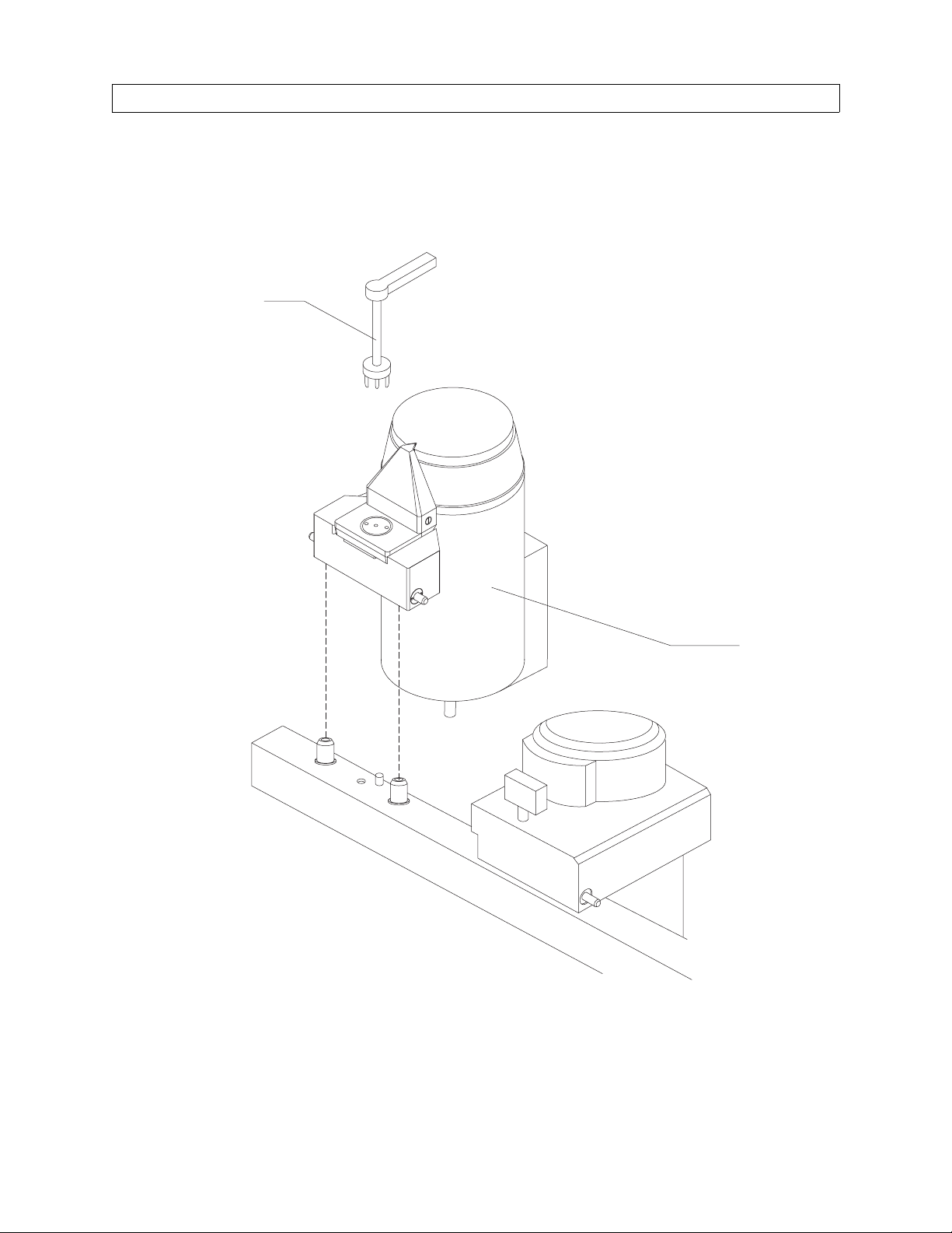
1.14 Locate the vaporizer lock down lever
at the rear of the vaporizer, and turn
the lever 90° counter-clockwise.
NOTE: Earlier units are not configured as
“User Removable” and therefore
require a special wrench (P/N
4114522) to be inserted into the
keyed spline which is covered by a
“DO NOT REMOVE” label. Remove
this label for access to the keyed
spline through the rocker plate at the
rear of the vaporizer, and turn the
tool 90° counter-clockwise. See
Figure 1.
1.15 Verify that the exclusion slider bar is
disengaged from the vaporizer being
removed.
1.16 Hold the vaporizer with two hands
and lift it up until it clears the
mounting block, then bring it
forward to clear the machine.
2.0 Machine Preparation:
2.1 Before installing a vaporizer,
perform a fresh gas leak test at the
fresh gas outlet to verify gas circuit
integrity. Refer to the device service
manual for specific instructions.
2.2 Examine the vapor mount O-rings
and replace them if needed.
¡¡¡¡WARNING: The O-rings supplied with
this vaporizer are incompatible for
use on the Narkomed 6000,
Narkomed GS Euro, Narkomed M,
Fabius GS or the USA manufactured
Fabius. These systems shall use only
O-ring #113 (NITRILE) P/N 4115864.
Note: The following two steps apply to
the Narkomed Mobile and Fabius
machines.
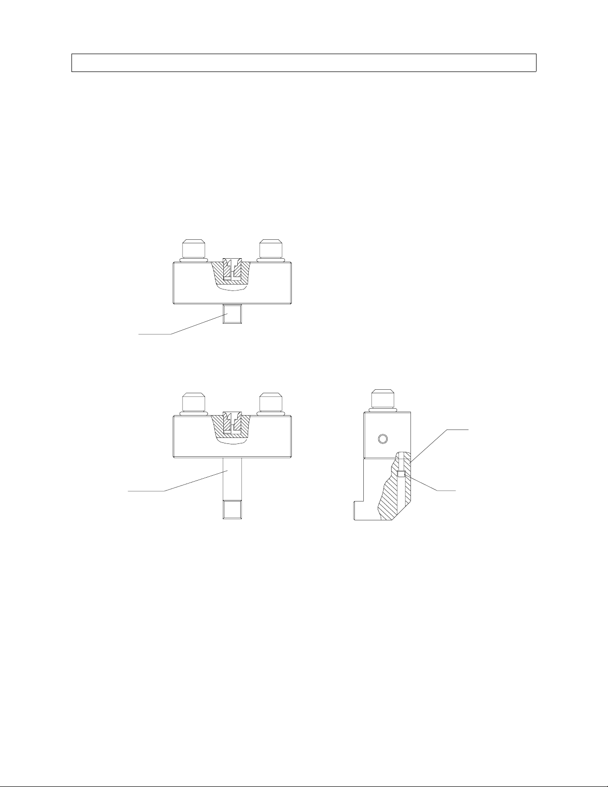
2.3 Verify the correct vaporizer support
block is installed on the vaporizer
mount. See Figure 2.
2
Page 5
Installation Procedure (continued)
LOCK DOWN TOOL
P/N 4114522
RETURN TO SERVICE PROCEDURE TABLE OF CONTENTS
RETURN TO CD-ROM TABLE OF CONTENTS
FIGURE 1. Vapor 19.3 Vaporizer Installation
VAPOR 19.3
MOUNT
VAPORIZER
SP18901
3
Page 6
RETURN TO SERVICE PROCEDURE TABLE OF CONTENTS
Installation Procedure (continued)
¡¡¡¡WARNING: Do not install a D-Tec
vaporizer on a Narkomed Mobile or
Fabius without the correct vaporizer
support block as this will result in an
incorrect fit and may cause leaks in the
fresh gas delivery system. Refer to this
procedure to verify correct vaporizer
support block prior to D-Tec vaporizer
mounting.
RETURN TO CD-ROM TABLE OF CONTENTS
2.4 If applicable, remove the original
vaporizer support block and install
the appropriate vaporizer support
block using the original hardware as
shown in Figure 2.
SP18902
INCORRECT
VAPORIZER
SUPPORT BLOCK
CORRECT
VAPORIZER
SUPPORT BLOCK
FIGURE 2. Vaporizer Support Block
(NM Mobile and Fabius only)
VAPORIZER
SUPPORT BLOCK
P/N 4116999
USE EXISTING
SUPPORT BLOCK
HARDWARE (2X)
4
Page 7

RETURN TO SERVICE PROCEDURE TABLE OF CONTENTS
Installation Procedure (continued)
3.0 Vaporizer Preparation Procedure:
RETURN TO CD-ROM TABLE OF CONTENTS
¡¡¡¡Caution: Use only a Duracell 1604, or
VARTA Energy 2000 9-volt battery in
this vaporizer. If any other battery is
installed, it may damage the
vaporizer.
¡¡¡¡WARNING: The battery terminals
must be firmly clipped onto the
battery to help prevent a possible
disconnection when the vaporizer is
moved.
¡¡¡¡WARNING: When routing the mains
cord to the electrical supply, ensure
that it does not interfere with the
correct functioning of other
equipment.
BATTERY COVER
SECURING SCREW
3.1 Invert the vaporizer, unscrew the
battery cover and remove the battery
from the base of the vaporizer as
illustrated in Figure 3.
3.2 Attach the battery terminals firmly
onto the new battery, observing the
correct polarity. Insert the battery
into the vaporizer and tighten the
cover screw.
BATTERY
CONNECTOR
SP18903
FIGURE 3. Vaporizer Battery Installation
VAPORIZER
(INVERTED)
DURACELL 1604
OR VARTA
ENERGY 2000
BATTERY
5
Page 8

Installation Procedure (continued)
RETURN TO SERVICE PROCEDURE TABLE OF CONTENTS
RETURN TO CD-ROM TABLE OF CONTENTS
3.3 Remove the mains lead retaining
plate illustrated in Figure 4. Fit the
power cord to the channel, and then
reinstall the power cord retaining
plate.
SP18904
3.4 Feed the mains lead around the back
of the vaporizer.
MAINS LEAD
MAINS LEAD
CHANNEL
FIGURE 4. Fitting the Mains Lead
MAINS LEAD
RETAINING PLATE
6
Page 9

Installation Procedure (continued)
RETURN TO SERVICE PROCEDURE TABLE OF CONTENTS
RETURN TO CD-ROM TABLE OF CONTENTS
4.0 Vaporizer Installation and Initial
Checks:
¡¡¡¡Caution: Use only the Dräger plug-in
mounting system.
¡¡¡¡WARNING: Do not install a D-Tec
vaporizer in the right hand position of
a Narkomed 6000 as this will result in
an incorrect fit and may cause leaks in
the fresh gas delivery system.
LOCKING LEVER
(SHOWN IN UNLOCKED POSITION)
4.1 Remove the protective plugs from the
vaporizer’s ports.
4.2 Verify that the locking lever is set to
the “unlocked” position. See Figure 5.
With both hands, hold the main body
of the vaporizer in an upright
position and lower it onto the mount,
ensuring that the vaporizer ports
correctly engage the port valves.
MANIFOLD
PORT
SP18905
O-RING
TURN TO LOCK
FIGURE 5. Vaporizer Installation
7
Page 10

Installation Procedure (continued)
RETURN TO SERVICE PROCEDURE TABLE OF CONTENTS
RETURN TO CD-ROM TABLE OF CONTENTS
¡¡¡¡Caution: The vaporizer must be
completely seated horizontally onto
the system manifold ports and
should not require excessive force to
attach.
4.3 Lock the vaporizer onto the manifold
by turning its locking lever 90°
clockwise. See Figure 5.
4.4 Verify that the vaporizer cannot be
lifted off the manifold and is fully
seated on the block.
4.5 Connect the power cord from the
vaporizer to an approved hospital
grade outlet.
¡¡¡¡Caution: Do Not use the convenience
receptacle on the Dräger machine.
4.6 Press the D-Tec Audio Mute key for
at least four seconds and verify that
the alarm and display test is
automatically operated for a period
of approximately two seconds as
follows:
• Each light and all the LCD agent
level indicator bars on the front
display panel flash four times.
• The audio alarm is activated four
times.
4.7 At the end of the test sequence,
verify that the amber LOW AGENT
lamp is illuminated.
5.0 Filling the Vaporizer:
¡¡¡¡WARNING: Do Not fill the vaporizer
with any substance other than
Suprane™ (desflurane). If any
substance other than Suprane™
(desflurane) is used, patient injury
could occur.
¡¡¡¡WARNING: Do Not fill the vaporizer
during testing.
¡¡¡¡WARNING: The vaporizer must only
be filled when it is in an upright
position. Failure to observe this
precaution may result in the
vaporizer being overfilled.
¡¡¡¡WARNING: The vaporizer must only
be filled when it is connected to an
electrical supply. This enables
observation of the agent level on the
display. Do Not attempt to fill the
vaporizer when the level display
indicates that it is full.
5.1 Remove the Suprane™ (desflurane)
bottle cap and ensure that the O-ring
is correctly fitted to the bottle probe.
5.2 Insert the bottle probe into the filler
port on the vaporizer, and push the
bottle firmly against the spring
pressure until it is fully engaged
with the filler port.
4.8 Verify that the ALARM BATTERY
LOW indicator is Not illuminated.
8
Page 11

Installation Procedure (continued)
RETURN TO SERVICE PROCEDURE TABLE OF CONTENTS
RETURN TO CD-ROM TABLE OF CONTENTS
¡¡¡¡WARNING: Ensure that the bottle is
fully engaged into the filler port
before attempting to lift the bottle. If
the bottle can not easily be lifted, do
not force it - otherwise the valve may
be broken.
5.3 When the probe cannot be inserted
any further into the filler port,
attempt to lift the bottle upwards.
ENSURE BOTTLE IS
5.4 If the bottle cannot easily be lifted, it
may be because the bottle has not
been completely inserted. Therefore,
firmly push the bottle straight into
the filler port to its full extent to
make sure that it is fully inserted.
5.5 When the bottle moves easily, lift it
upward to lock the bottle onto the
filler port as illustrated in Figure 6.
FULLY ENGAGED
IN FILLER PORT
SP18906
LIFT BOTTLE
UPWARDS TO FILL
FIGURE 6. Starting Vaporizer Fill
5.6 When the bottle reaches the upper
stop, bubbling of agent will occur for
a period of up to 45 seconds before
the agent flows from the bottle
through the filler port and into the
vaporizer.
5.7 Hold the bottle in position at the
upper stop and continue filling until
the bottle is empty or the indicator
on the front panel shows that the
sump is full.
9
Page 12

Installation Procedure (continued)
RETURN TO SERVICE PROCEDURE TABLE OF CONTENTS
RETURN TO CD-ROM TABLE OF CONTENTS
¡¡¡¡WARNING: Grip the bottle firmly
while rotating it downwards from
the upper stop to the lower stop
position, and hold the bottle firmly in
the filler port until the small amount
of agent in the filler has drained
back into the bottle. Failure to do so
may result in spilled agent.
5.8 Grip the bottle firmly and lower it
from the upper stop position to the
lower stop position as shown in
Figure 7.
5.9 When the bottle reaches the lower
stop position, hold the bottle firmly
in the filler port for a minimum of 5
seconds to allow the small amount of
agent in the filler system to drain
back into the bottle.
5.10 To avoid dropping the bottle, support
the bottle as it is automatically
unlocked from the filler port and
released from the filler.
SP18907
FIGURE 7. Stopping the Fill
10
Page 13

Installation Procedure (continued)
RETURN TO SERVICE PROCEDURE TABLE OF CONTENTS
RETURN TO CD-ROM TABLE OF CONTENTS
6.0 Testing Procedure:
6.1 After a warm-up period of up to 10
minutes, verify that the amber
WARM-UP light extinguishes and
the green OPERATIONAL light
illuminates, indicating the vaporizer
is ready for use.
6.2 Turn off all vaporizers and perform a
low-pressure fresh gas leak test as
described in the relevant anesthesia
machine’s operator’s or service
manual.
6.3 Turn the D-Tec vaporizer to the 1%
setting by fully depressing the
release bar at the rear of the dial,
and then turning the dial. Repeat the
fresh gas leak test.
6.4 Disconnect the vaporizer AC power
cord. Wait for at least 15 seconds and
verify that the red NO OUTPUT
light and audio alarm are activated.
7.1.2 Turn on the safety analyzer and
set the function switch to the
GROUND WIRE RESISTANCE
position. Attach the test lead to
the SINGLE LEAD connector.
7.1.3 Set the safety analyzer GROUND
switch to the NORMAL position.
Set the POLARITY switch to the
OFF position.
7.1.4 The safety analyzer shall indicate
Ω or less when the test lead is
0.1
applied to the cylinder yoke.
7.2 Chassis Leakage Current
7.2.1 Set the safety analyzer to the
CHASSIS LEAKAGE CURRENT
position.
7.2.2 Record the total leakage current
with the polarity and ground
switches set to the following
positions:
¡¡¡¡Caution: Do Not use the convenience
receptacle on the Dräger machine.
7.0 Electrical Safety Testing:
7.1 Protective Ground Continuity
Note: Do not plug the safety analyzer into
a line isolation monitor as inaccurate
readings may occur. To prevent an
alternate path to ground, the
anesthesia’s AC power cord must be
temporarily disconnected.
7.1.1 Plug the D-Tec vaporizer power
cord into the safety analyzer, and
plug the power cord of the safety
analyzer into a 120 VAC
receptacle.
Ground
Polarity
Open Normal
Normal Normal
Open Reversed
Normal Reversed
Verify that the leakage current is
250 microamps or less in each of
the switch positions.
7.2.3 Connect the anesthesia machine’s
AC power cord to a hospital grade
outlet.
7.2.4 Reconnect the vaporizer AC
power cord to a hospital grade
outlet.
11
Page 14

Installation Procedure (continued)
RETURN TO SERVICE PROCEDURE TABLE OF CONTENTS
RETURN TO CD-ROM TABLE OF CONTENTS
8.0 Concentration Verification:
8.1 While depressing the opposite
vaporizer’s “0” release button, verify
that its handwheel can not be
turned.
8.2 Move the exclusion lever to the
opposite position. Verify that the
slider bar disengages the original
vaporizer and engages the D-Tec
without binding. Verify that the DTec vaporizer can not be turned on.
Press the opposite vaporizer’s “0”
release button and verify that its
handwheel can be turned. Return all
vaporizers to “0”.
8.3 Verify that the Riken Gas Indicator
Model 18D bears a current
calibration sticker.
8.4 Zero the Riken as per its operator’s
manual.
8.5 Activate the waste gas scavenger.
8.6 Configure the anesthesia machine’s
gas delivery system to test the
installed vaporizers output
concentration. Refer to the device
service manual for specific
instructions.
8.7 Set the oxygen flow rate to 5.0 L/min.
and verify all other gases are at “0”.
8.8 Verify that the Riken indicates 0.0%
vol. and re-zero if needed.
8.9 Move the exclusion lever to allow
activation of the D-Tec vaporizer.
8.11 Draw a gas sample into the Riken
and read the gas volume % per the
operator’s manual. Record the
reading on the desflurane vaporizer
concentration verification form.
8.12 Verify that the value obtained is
within the sum tolerances of the
Riken and the vaporizer. (Refer to
the desflurane vaporizer
concentration verification form for
High and Low limits.) Place a check
mark in the appropriate Pass/Fail
box on the form.
Note: The D-Tec vaporizer is calibrated by
the manufacturer at an ambient
pressure of 760 mm Hg (sea level).
The partial pressure of the delivered
agent at any selected dial setting
varies directly with changes in
ambient air pressure. Refer to the
operator’s instruction manual for
required dial settings at higher
altitudes.
8.13 Repeat the previous steps at
desflurane vaporizer dial settings of
6%, 10%, 12% and 16%.
Note: The dial release must be depressed
again to obtain the 16% setting.
8.14 Turn the vaporizer to the “0”
position.
8.15 Press the O2 Flush to purge the
system of residual agent. Close the
O2 flow control valve and return all
controls to their original settings.
8.10 Press the dial release bar and rotate
the dial to the 4% setting.
12
Page 15

RETURN TO SERVICE PROCEDURE TABLE OF CONTENTS
RETURN TO CD-ROM TABLE OF CONTENTS
DESFLURANE VAPORIZER CONCENTRATION VERIFICATION
Customer _________________________________ AHA # ____________________________
Address _________________________________ Dealer ____________________________
City _____________________________________ State ___________ Zip ______________________
PO # _____________ Machine Serial # _______________ Vaporizer Serial # _____________
Machine Model ____________________________
Dial
Setting
4% 3.28% 4.72%
6% 4.92% 7.08%
10% 8.20% 11.8%
12% 9.84% 14.16%
16% 13.12% 18.88%
Low Lim.
Tol erance
High Lim.
Tol erance
Pass Fail
Comments___________________________________________________________________
_____________________________________________________________________________________
____________________________________________________________________________
Service Representative: I.D. No.: Date:
S010245-
Page 16

RETURN TO SERVICE PROCEDURE TABLE OF CONTENTS
RETURN TO CD-ROM TABLE OF CONTENTS
Page 17

RETURN TO SERVICE PROCEDURE TABLE OF CONTENTS
RETURN TO CD-ROM TABLE OF CONTENTS
Page 18

RETURN TO SERVICE PROCEDURE TABLE OF CONTENTS
RETURN TO CD-ROM TABLE OF CONTENTS
DrägerService is a division of
Draeger Medical, Inc.
3122 Commerce Drive
Telford, PA 18969
Tel: (215) 721-5402
(800) 543-5047
Fax: (215) 721- 5784
Web: www.draegermedical.com
Printed in the U.S.A.
 Loading...