

Page 1

North
A
merican
Dräger
RETURN TO CD-ROM TABLE OF CONTENTS
Operator’s Instruction Manual
Part Number: 4112258-018
Rev: C
Date: 30 September 1999
© 1999 N.A.D., Inc.
Narkomed 2C
Anesthesia System
Page 2

RETURN TO CD-ROM TABLE OF CONTENTS
Page 3

Narkomed 2C
Operator’s Instruction Manual
Table of Contents
Section 1: Introduction
Operator’s Responsibility for Patient Safety ................................... 1-1
Limitation of Liability ................................................... 1-2
Restriction .......................................................... 1-2
Symbol Definition ..................................................... 1-2
How This Manual Is Organized ........................................... 1-3
Conventions Used in This Manual ......................................... 1-3
General Warnings and Cautions ........................................... 1-3
Section 2: General Description
Overview ........................................................... 2-1
Gas Delivery System ................................................... 2-1
Vaporizers ......................................................... 2-11
Absorber .......................................................... 2-12
Bain Circuit Adapters .................................................. 2-15
Scavenger Systems ................................................... 2-17
AV2+ Ventilator ...................................................... 2-19
Main Switch Panel .................................................... 2-20
Power Supply System ................................................. 2-22
Breathing System Sensor Interface Panel ................................... 2-24
Adjustable Display Arm ................................................ 2-25
Monitoring System .................................................... 2-25
Display Screen ...................................................... 2-26
Control Key Panel .................................................... 2-26
Datagrip ........................................................... 2-27
Datascan Display .................................................... 2-28
Central Alarm Display and Audio Alarm Annunciation .......................... 2-30
Manual Sphygmomanometer ............................................ 2-33
O.R. Data Manager ................................................... 2-33
RETURN TO CD-ROM TABLE OF CONTENTS
Section 3: Daily Checkout
Daily Checkout Procedure ............................................... 3-1
Section 4: Preuse Checkout
Preuse Checkout Procedure ............................................. 4-1
Section 5: Operation
Gas Delivery System
Overview .................................................... 5-1-1
Connecting the Pipeline Gas Supply ................................. 5-1-1
Connecting the Gas Cylinders .....................................5-1-2
Connecting the Fresh Gas Hose .................................... 5-1-4
Adjusting the Gas Flow .......................................... 5-1-4
Using the Oxygen Flush .......................................... 5-1-4
i
Page 4

Narkomed 2C
Operator’s Instruction Manual
Table of Contents
Vaporizer
Overview .................................................... 5-2-1
Filling Systems ................................................ 5-2-1
North American Dräger Exclusion System ............................. 5-2-2
Operating the Vaporizers ......................................... 5-2-3
Filling the Vaporizer ............................................. 5-2-4
Filling the Vaporizer During a Case .................................. 5-2-5
Draining the Vaporizer .......................................... 5-2-11
Absorber System
(Refer to separate manual) ....................................... 5-3-1
Bain Circuit Adapter
(Refer to separate manual) ....................................... 5-4-1
Open Reservoir Scavenger
Overview .................................................... 5-5-1
Connecting the Open Reservoir Scavenger System ...................... 5-5-2
Operating the Open Reservoir Scavenger System ....................... 5-5-3
RETURN TO CD-ROM TABLE OF CONTENTS
Scavenger Interface for Passive Systems
Overview .................................................... 5-6-1
Operating the Scavenger Interface for Passive Systems ................... 5-6-2
Main Switch Panel
Overview .................................................... 5-7-1
System Power Switch ........................................... 5-7-1
Testing the Battery .............................................5-7-2
AV2+ Anesthesia Ventilator
Overview .................................................... 5-8-1
Activating the Ventilator .......................................... 5-8-2
Adjusting the Tidal Volume ........................................ 5-8-4
Setting the Respiratory Frequency .................................. 5-8-4
Setting the Inspiratory/Expiratory (I:E) Phase
Time Ratio ...................................................5-8-5
Setting the Inspiratory Flow Rate ................................... 5-8-5
Setting the Inspiratory Pressure Limit ................................ 5-8-5
Problem Resolution ............................................. 5-8-6
Monitoring System
Overview .................................................... 5-9-1
Power-On Screen .............................................. 5-9-4
Using the Screen Selection Menu ................................... 5-9-5
Invoking the Machine Monitor Screen ................................ 5-9-6
Invoking a System Monitor Screen .................................. 5-9-8
Invoking the CO2System Monitor Screen ............................ 5-9-10
Invoking the NIBP System Monitor Screen ........................... 5-9-11
Invoking the Breathing Pressure System Monitor Screen ................. 5-9-11
Invoking the Respiratory Volume System Monitor Screen ................. 5-9-12
Invoking the Agent System Monitor Screen ........................... 5-9-13
Invoking the Pulse Oximetry System Monitor Screen .................... 5-9-14
ii
Page 5

Narkomed 2C
Operator’s Instruction Manual
Table of Contents
Setting Up the Monitoring System .................................. 5-9-14
Invoking the Templates Subscreen ................................. 5-9-17
Configuring the Monitoring System ................................. 5-9-21
Invoking the System Configure Screen .............................. 5-9-22
Invoking the Auto Log Screen .................................... 5-9-27
Invoking the Serial Ports Screen ................................... 5-9-29
Invoking the Datascan Configure Screen ............................. 5-9-34
Invoking the Preuse Checkout Screen ............................... 5-9-36
Invoking the Data Log Screen .................................... 5-9-38
Invoking the Data Management Screen .............................. 5-9-41
Oxygen Monitoring
Overview ................................................... 5-10-1
Monitor Display ............................................... 5-10-1
Setting Alarm Limits ............................................ 5-10-2
Calibrating the Oxygen Sensor .................................... 5-10-3
Oxygen Alarm Messages ........................................ 5-10-6
Low Oxygen Supply Whistle ...................................... 5-10-7
Problem Resolution ............................................ 5-10-8
RETURN TO CD-ROM TABLE OF CONTENTS
Respiratory Volume Monitoring
Overview ................................................... 5-11-1
Monitor Display ............................................... 5-11-2
Setting Minute Volume Low Limit .................................. 5-11-3
Setting Volume Alarms On/Off .................................... 5-11-4
Setting Minute Volume Trend Scale ................................ 5-11-4
Respiratory Volume Alarm Messages ............................... 5-11-5
Problem Resolution ............................................ 5-11-7
Breathing Pressure Monitoring
Overview ................................................... 5-12-1
Installing the Breathing Pressure Pilot Line ........................... 5-12-1
Choice of Breathing Pressure Monitoring Location ...................... 5-12-2
Monitor Display ............................................... 5-12-4
Setting Pressure High and Threshold Pressure Alarm Limits .............. 5-12-5
Setting Apnea Alarm On/Off ...................................... 5-12-7
Setting Auto-Threshold ......................................... 5-12-7
Setting Pressure Trend Scale ..................................... 5-12-7
Breathing Pressure Alarm Messages ............................... 5-12-8
Problem Resolution ........................................... 5-12-10
Manual Sphygmomanometer
Overview ................................................... 5-13-1
Selecting a Blood Pressure Cuff ................................... 5-13-2
Connecting the Cuff ............................................ 5-13-2
Placing the Cuff ............................................... 5-13-3
O.R. Data Manager
Overview ................................................... 5-14-1
Central Processing Unit with Floppy Disk Drive and Network Interface ....... 5-14-3
Keyboard ................................................... 5-14-3
Display Screen ............................................... 5-14-5
iii
Page 6

Narkomed 2C
Operator’s Instruction Manual
Table of Contents
Handling Floppy Disks .......................................... 5-14-6
General Operation ............................................. 5-14-8
Pop-up Menus ............................................... 5-14-12
Using the O.R. Data Manager ................................... 5-14-17
Starting a Case with a Floppy Disk-Based O.R. Data Manager ............ 5-14-17
Disk Error Messages .......................................... 5-14-27
Starting a case with a Network-Based O.R. Data Manager ............... 5-14-28
Data Recording During the Case ................................. 5-14-34
Ending a Case with the O.R. Data Manager ......................... 5-14-35
Patient Data Screen .......................................... 5-14-38
Pre-Anesthesia Evaluation Screen ................................ 5-14-52
Drug Administration Screen ..................................... 5-14-55
O.R. Event Record Screen ...................................... 5-14-65
QA Indicators ............................................... 5-14-78
Numeric Data Screen ......................................... 5-14-84
Graphic History Screen ....................................... 5-14-101
Printing Anesthesia Records ................................... 5-14-106
System Configuration Screen ................................... 5-14-109
Set Current Templates Sub-screen ............................... 5-14-110
Configuration Options Sub-screen ................................ 5-14-112
Import Site Lists Sub-screen ................................... 5-14-121
Transfer Case Sub-screen ..................................... 5-14-123
Configure Numeric Screen Sub-screen ............................ 5-14-130
Install Default Templates Sub-screen ............................. 5-14-134
Screen Menu Sub-screen ...................................... 5-14-136
Service Functions Sub-screen .................................. 5-14-136
RETURN TO CD-ROM TABLE OF CONTENTS
Section 6: Cleaning and Routine Maintenance
Overview ........................................................... 6-1
Routine Maintenance ................................................... 6-1
Removing Parts for Cleaning and Disinfection ................................ 6-10
Disassembling Parts for Cleaning and Disinfection ............................. 6-13
General Guidelines for Cleaning and Disinfection ............................. 6-15
Reassembly Instructions ............................................... 6-22
Section 7: Specifications
General ............................................................ 7-1
Environmental ........................................................ 7-1
Electrical ........................................................... 7-1
Gas Delivery System ................................................... 7-1
Vaporizers .......................................................... 7-2
Ventilator ........................................................... 7-3
Absorber System ...................................................... 7-3
Oxygen Monitoring .................................................... 7-3
Breathing Pressure Monitoring ............................................ 7-4
Respiratory Volume Monitoring ............................................ 7-4
Serial Interface ....................................................... 7-5
Appendix - Spare and Replacement Parts ........................................ A-1
Index ..................................................................... I-1
iv
Page 7

RETURN TO CD-ROM TABLE OF CONTENTS
Section 1
Introduction
Operator’s
Responsibility for
Patient Safety
North American Dräger anesthesia products are designed to provide the
greatest degree of patient safety that is practically and technologically
feasible. The design of the equipment, the accompanying literature, and
the labeling on the equipment take into consideration that the purchase
and use of the equipment are restricted to trained professionals, and
that certain inherent characteristics of the equipment are known to the
trained operator. Instructions, warnings, and caution statements are
limited, therefore, to the specifics of the North American Dräger design.
This publication excludes references to hazards which are obvious to a
medical professional, to the consequences of product misuse, and to
potentially adverse effects in patients with abnormal conditions. Product
modification or misuse can be dangerous. North American Dräger
disclaims all liability for the consequences of product alterations or
modifications, as well as for the consequences which might result from
the combination of North American Dräger products with products
supplied by other manufacturers if such a combination is not endorsed
by North American Dräger.
The operator of the anesthesia system must recognize that the means of
monitoring and discovering hazardous conditions are specific to the
composition of the system and the various components of the system. It
is the operator, and not the various manufacturers or suppliers of
components, who has control over the final composition and
arrangement of the anesthesia system used in the operating room.
Therefore, the responsibility for choosing the appropriate safety
monitoring devices rests with the operator and user of the equipment.
Patient safety may be achieved through a variety of different means
depending on the institutional procedures, the preference of the
operator, and the application of the system. These means range from
electronic surveillance of equipment performance and patient condition
to simple, direct contact between operator and patient (direct
observation of clinical signs). The responsibility for the selection of the
best level of patient monitoring belongs solely to the equipment operator.
To this extent, the manufacturer, North American Dräger, disclaims
responsibility for the adequacy of the monitoring package selected for
use with the anesthesia system. However, North American Dräger is
available for consultation to discuss monitoring options for different
applications.
1-1
Page 8

Section 1
Introduction
RETURN TO CD-ROM TABLE OF CONTENTS
Limitation of
Liability
North American Dräger’s liability, whether arising from or related to the
manufacture and sale of the products, their installation, demonstration,
sales representation, use, performance, or otherwise, including any
liability based upon North American Dräger’s product warranty, is
subject to and limited to the exclusive terms of North American Dräger’s
limited warranty, whether based upon breach of warranty or any other
cause of action whatsoever, regardless of any fault attributable to North
American Dräger and regardless of the form of action (including, without
limitation, breach of warranty, negligence, strict liability, or otherwise).
North American Dräger shall in no event be liable for any
special, incidental, or consequential damages (including loss of
profits) whether or not foreseeable and even if North American
Dräger has been advised of the possibility of such loss or
damage. North American Dräger disclaims any liability arising
from a combination of its product with products from another
manufacturer if the combination has not been endorsed by North
American Dräger. Buyer understands that the remedies noted in
North American Dräger’s limited warranty are its sole and
exclusive remedies.
Furthermore, buyer acknowledges that the consideration for the
products, equipment, and parts sold reflects the allocation of
risk and the limitations of liability referenced herein.
Restriction
Symbol Definition
Federal law restricts this device to sale by, or on the order of, a
physician.
The following symbols appear on the label on the back of the Narkomed
2C and are defined below.
CAUTION: Refer to accompanying documents before
operating equipment.
ATTENTION: Consulter les documents ci-joints avant de
faire fonctionner l’apparail.
CAUTION: Risk of electric shock, do not remove cover.
Refer servicing to a North American Dräger
qualified technical service representative.
ATTENTION: Risque de choc electrique, ne pas enlever le
couvercle. Ne faire reparer que par un
representant technique autorise de North
American Dräger.
Degree of protection against electric shock: Type B.
Protection contre le risque de choc electrique: Type B.
1-2
Page 9

RETURN TO CD-ROM TABLE OF CONTENTS
Section 1
Introduction
These additional symbols are used on other locations of the Narkomed
2C to provide quick and easy recognition of product functions.
Oxygen Concentration
Breathing Pressure
Breathing Volume
Audible Alarm Disable
How This Manual Is
Organized
Conventions Used
in This Manual
All users of the Narkomed 2C must read this manual completely before
using the machine. In order to make this document more convenient for
future reference, it has been divided into several independent sections.
Section 2 - General Description provides a summary of Narkomed 2C
features and functions.
Section 3 - Daily Checkout contains the checkout procedures that must
done on a daily basis.
Section 4 - Preuse Checkout contains the checkout procedures to be
performed between successive cases.
Section 5 - Operation has detailed instructions on the use and operation
of each functional component of the system.
Section 6 - Routine Maintenance provides cleaning, maintenance, and
replacement procedures.
Section 7 - Specifications contains the specifications for all system
components.
This manual has been set up with several conventions to help organize
the information contained in it. Please read about these conventions
carefully so that you understand their significance in the manual.
Typefaces
Different typefaces are used throughout the manual to differentiate
between narrative information and machine messages and labels.
1-3
Page 10

Section 1
Introduction
RETURN TO CD-ROM TABLE OF CONTENTS
Warnings and
Cautions
General Warnings
and Cautions
All parts of this manual contain warning and caution statements about
the Narkomed 2C.
• Warning statements give important information that, if ignored,
could lead directly to a patient’s injury.
• Caution statements give important information that, if ignored, could
lead directly to equipment damage and, indirectly, to a patient’s
injury.
The following list of warnings and cautions apply to general operation
and maintenance of the Narkomed 2C. Warnings and cautions about
installing and operating specific parts appear with those topics.
WARNING: Any person involved with the setup, operation, or
maintenance of the Narkomed 2C anesthesia system must
be thoroughly familiar with this instruction manual.
WARNING: This anesthesia system will not respond automatically to
certain changes in patient condition, operator error, or
failure of components. The system is designed to be
operated under the constant surveillance and control of a
qualified operator.
WARNING: No third-party components shall be attached to the
anesthesia machine, ventilator, or breathing system
(except for certain approved exceptions). Contact the North
American Dräger technical service department for further
information.
WARNING: When moving the anesthesia machine, remove all monitors
and equipment from the top shelf, remove the absorber
system, and use only the machine handles or push/pull
bars. The anesthesia machine should only be moved by
people who are physically capable of handling its weight.
North American Dräger recommends that two people move
the anesthesia machine to aid in maneuverability. Exercise
special care so that the machine does not tip when moving
up or down inclines, around corners, and across thresholds
(for example, in door frames and elevators). Do not
attempt to pull the machine over any hoses, cords, or other
obstacles on the floor.
1-4
Page 11

RETURN TO CD-ROM TABLE OF CONTENTS
Section 1
Introduction
CAUTION: Although the Narkomed 2C is designed to minimize the
effects of ambient radio-frequency interference, machine
functions may be adversely affected by the operation of
electrosurgical equipment or short wave or microwave
diathermy equipment in the vicinity.
CAUTION: Communications with external equipment may be
temporarily affected by electromagnetic interference due to
the use of electrosurgical equipment.
CAUTION: Do not place sensitive electronic equipment on or adjacent
to the display screen.
CAUTION: Do not place more than 100 pounds on top of the
Narkomed 2C monitor housing.
Recommendations
In the interest of patient safety, North American Dräger strongly
advocates the use of an oxygen analyzer, pressure monitor, and
either a volume monitor or an end-tidal CO
monitor in the breathing
2
circuit at all times.
Because of the sophisticated nature of North American Dräger
anesthesia equipment and its critical importance in the operating
room setting, it is highly recommended that only appropriately
trained and experienced professionals be permitted to service and
maintain this equipment. Please contact North American Dräger’s
Technical Service Department at (800) 543-5047 for service of this
equipment.
North American Dräger also recommends that its anesthesia
equipment be serviced at three-month intervals. Periodic
Manufacturer’s Service Agreements are available for equipment
manufactured by North American Dräger. For further information
concerning these agreements, contact the North American Dräger
Technical Service Department at (800) 543-5047.
1-5
Page 12

RETURN TO CD-ROM TABLE OF CONTENTS
Page 13
A
S
V
S
S
A
RETURN TO CD-ROM TABLE OF CONTENTS
Section 2
General Description
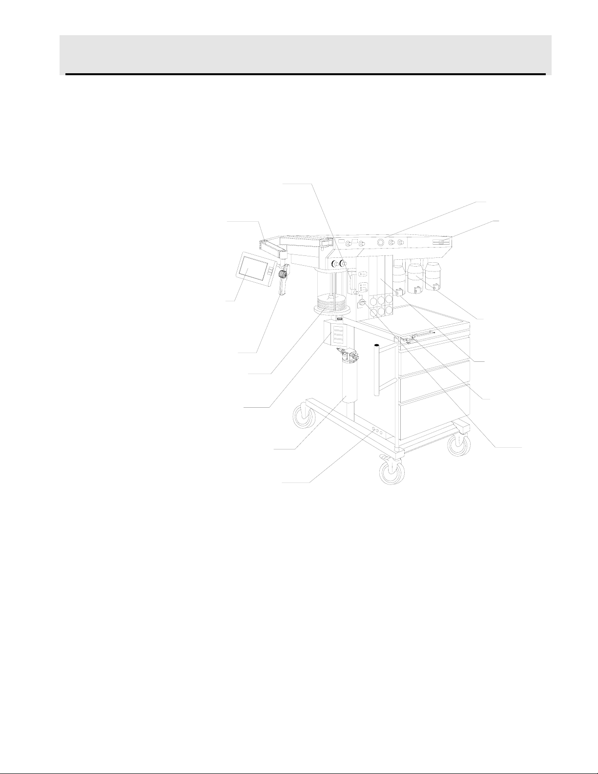
Overview
The Narkomed
®
2C is a continuous flow anesthesia system. All
Narkomed 2C machines are equipped with a monitoring system and
pneumatic circuitry for delivering gases and anesthetic vapor. A front
view of the Narkomed 2C is shown in the figure below.
UXILIARY OXYGEN
FLOWMETER (OPTIONAL)
DISPLAY
RM
DISPLAY
CREEN
DATAGRIP
ENTILATOR
BELLOWS
BREATHING
YSTEM SENSOR
INTERFACE PANEL
OPEN RESERVOIR
CAVENGER
CIRCUIT BREAKERS
VENTILATOR
O.R. DATA
MANAGER
(OPTIONAL)
VAPORIZERS
(OPTIONAL)
FLOWMETER
BANK
FRESH GAS
OUTLET
MAIN
SWITCH
PANEL
OP20999
Gas Delivery
System
The pneumatic system can simultaneously deliver up to four gases and
one anesthetic agent (from a selection of up to three). Oxygen and
nitrous oxide are standard on all Narkomed 2C machines. Optional
gases are air and carbon dioxide. Gas is supplied to the system through
pipelines and cylinders. Connections for oxygen and nitrous oxide are
standard on all machines, and a pipeline connection for air is also
available. Gas cylinder yokes are available for up to two oxygen
cylinders and two nitrous oxide cylinders, plus one additional cylinder
for a third gas.
2-1
Page 14

Section 2
General Description
RETURN TO CD-ROM TABLE OF CONTENTS
Color Coding
Gas Entry Through a
Pipeline
Each connection, valve, gauge, and flowmeter is labeled and color-coded
for the appropriate gas, as shown in the table below.
GAS SYSTEM COLOR CODING
GAS MARKING USA GERMANY ISO
Air AIR Yellow Yellow Black/White
Checkered
Carbon Dioxide CO
Nitrous Oxide N2O Blue Gray Blue
Oxygen O
2
2
Gray Black Gray
Green Blue White
Gas from the hospital pipelines enters the Narkomed 2C through hoses
connected to indexed pipeline inlets located on the side of the flowmeter
housing. The indexed connector system reduces the risk of delivering the
wrong gas to a patient by preventing incorrect connection of gas pipes.
The inlets include check valves, which prevent backflow leakage into the
atmosphere (when supply hoses are not connected) or into the attached
supply hoses (when reserve cylinders are in use). Each pipeline
connection is equipped with a filter to prevent foreign material from
entering the internal gas piping of the Narkomed 2C. Pipeline gases
should be supplied at 50–55 psi.
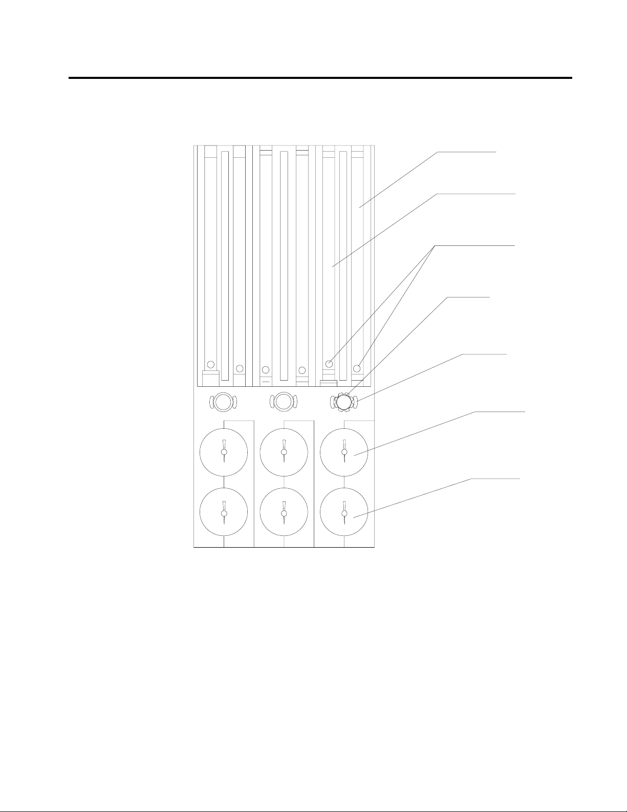
Pipeline Pressure
Gauges
Pipeline pressure gauges for oxygen and nitrous oxide are standard. If
the anesthesia machine is equipped with air, a pipeline pressure gauge
for air is also included. These gauges are located directly below their
corresponding flowmeters and flow control valves. They are labeled and
color-coded for their respective gases on the flowmeter shield. Concentric
scales in psi and kPa indicate the pipeline supply pressure. A typical
pressure gauge and flowmeter arrangement is shown in the following
figure.
2-2
Page 15
10
9
8
7
6
5
4
3
2
1
10
9
8
7
6
5
4
3
2
1
1
2
3
4
5
6
7
8
9
10
1000
1000
900
800
700
600
500
400
300
200
100
900
800
700
600
500
400
300
200
100
100
200
300
400
500
600
700
800
900
1000
COARSE FLOW
TUBE (l/min)
FINE FLOW
TUBE (ml/min)
INDICATOR
FLOATS
FLOWMETER
GUARD KNOB
FLOW CONTROL
VALVE
PIPELINE
PRESSURE
GAUGE
CYLINDER
PRESSURE
GAUGE
OP10006
THREE-GAS FLOWMETER
AND PRESSURE GAUGE ASSEMBLY
PIPELINE
CYLINDER
PIPELINE
CYLINDER
AIR O
2
N2O
PIPELINE
CYLINDER
N2O
AIR
O
2
RETURN TO CD-ROM TABLE OF CONTENTS
Section 2
General Description
When the machine is connected to an active pipeline supply, each gauge
should indicate 50–55 psi. A deviation from within this range indicates
that the pipeline gas supply system is improperly adjusted and may
adversely affect the operation of the Narkomed 2C. For example, a
fluctuating pipeline supply pressure would cause a corresponding
fluctuation of the gas flow delivered from that pipeline. An excessively
low pipeline pressure may activate the corresponding reserve cylinder
and deplete its contents (if the reserve cylinder valve was left in the
open position).
CAUTION: To ensure that gas supplies are at adequate pressure,
pipeline pressure gauges should indicate steady pressures
of 50–55 psi.
2-3
Page 16

Section 2
General Description
RETURN TO CD-ROM TABLE OF CONTENTS
Gas Entry Through
Cylinder Yokes
The Narkomed 2C can be equipped with a maximum of two oxygen and
two nitrous oxide cylinder hanger yokes. An additional yoke for an
optional third gas is also available. To prevent a cylinder from being
improperly connected, the yokes are labeled, color-coded, and keyed for
gas-specific cylinders using the pin-indexed safety system.
A filter within each yoke prevents foreign material from entering the
internal gas piping. A check valve in each yoke prevents leakage into the
atmosphere if the cylinder is not mounted on the yoke. When the
machine is configured with two yokes for the same gas, the check valve
prevents movement of gas from one cylinder to the other. If a cylinder is
not mounted to a yoke, the attached yoke plug should be placed between
the yoke handle’s threaded bolt and the yoke’s gas inlet.
When attaching a cylinder, make sure that only one washer is installed
between the cylinder and the yoke gas inlet. Using multiple washers
may compromise the pin-indexed safety system. Be sure to verify the
integrity of both index pins whenever you install a new cylinder.
WARNING: Check cylinder yokes for the presence of two index pins
each time you attach a cylinder to the machine. Use only
one cylinder gasket per yoke. Using more than one gasket
could cause leakage of the cylinder gas and compromise
the pin-indexed safety system.
Cylinders attached to the hanger yokes must contain gas at the
recommended pressures outlined in the following table. Replace any
cylinders with less than the recommended pressure (psi-min) with full
cylinders.
GAS PSI - FULL* PSI - MIN*
Air 1900 1000
Carbon Dioxide 838 600
Nitrous Oxide 745 600
Oxygen 1900 1000
*Indicated pressures are for E-size cylinders at 70° F (21° C).
2-4
Page 17

RETURN TO CD-ROM TABLE OF CONTENTS
Section 2
General Description
Cylinder Pressure
Gauges
Oxygen Supply
Pressure Failure
Protection Device
(OFPD)
Each cylinder gas circuit has a cylinder pressure gauge, located at the
bottom of the flowmeter panel on the front of the machine (see the
Flowmeter and Pressure Gauge Assembly figure earlier in this section.)
Each gauge is labeled and color-coded on the flowmeter housing for its
respective gas. When a cylinder’s valve is open, its pressure gauge
indicates the gas pressure in the cylinder. The dial is marked with
concentric scales for psi and kPa. If two reserve cylinders of the same
gas are open at the same time, the gauge indicates the pressure in the
cylinder having the higher pressure.
For nonliquefied gases (oxygen, air), the indicated pressure is
proportional to the gas content of the cylinder. For liquefied gases
(nitrous oxide, carbon dioxide), the gauge indicates the vapor pressure of
the liquefied gas in the cylinder. This pressure remains constant until
all of the liquid in the cylinder has vaporized. When the liquid has
vaporized, the cylinder pressure decreases proportionally as gas is
removed from the cylinder.
The oxygen failure protection device (OFPD) is a pneumatically operated
valve that protects the patient in the event of partial or complete oxygen
pressure loss. All gas circuits, except the oxygen circuit, are controlled by
these valves. OFPD-controlled valves respond to the gas pressure in the
oxygen supply line. When oxygen pressure is adequate, the valves open
for unrestricted gas flow. When oxygen pressure is reduced or lost, the
valves to close proportionally to the loss. Controlled gases are restricted
or shut down without affecting the oxygen flow.
Gas flow reductions are indicated on the flowmeters. When oxygen
supply pressure drops below about 37 psi, an oxygen supply pressure
alarm is activated, resulting in the following:
• The Caution message O2 SUPPLY LOW appears on the central
alarm display.
• The red O
SUPPLY PRESSURE indicator on the main switch
2
panel lights.
• An intermittent audible alarm sounds.
• A 7-second whistle may sound, depending on the machine’s
configuration.
NOTE: When one source of oxygen pressure (either pipeline or
reserve cylinders) fails, but the other source maintains proper
supply pressure in the oxygen supply lines, the oxygen supply
pressure alarms are not activated.
2-5
Page 18

Section 2
General Description
RETURN TO CD-ROM TABLE OF CONTENTS
Flowmeters
Low-Flow Flowmeters
(Optional)
Minimum Oxygen
Flow
Flow Control Valves
Flowmeters, located directly above their corresponding flow control
valves, indicate the delivered flow rate of each gas in the fresh gas
mixture. Dual flowmeter tubes (fine and coarse) are used in tandem for
oxygen, nitrous oxide, and air (if provided). When other gases are
supplied, single flowmeter tubes are used. All flowmeters are color-coded
and labeled at the lower end of the flowtube. A typical flowmeter
arrangement is shown in the Flowmeter and Pressure Gauge Assembly
figure earlier in this section.
Each flowmeter has a float indicator. To determine the flow rate, read
the flowmeter scale at the center of the float.
For low-flow anesthesia, the Narkomed 2C can be configured with lowflow, dual-tube flowmeters for oxygen and nitrous oxide. These
flowmeters function the same way as the standard dual-tube flowmeters,
but they are calibrated to provide greater resolution for low-flow
anesthesia.
The oxygen dispensing system incorporates a calibrated bypass flow of
150 ±50 ml/min (at 50 psi pipeline pressure), which delivers this volume
of oxygen even if the oxygen flow control valve is fully closed.
A needle valve is located below the fine flowmeter tube for each gas.
This valve is used to adjust the flow of gas. Turning the valve knob
counterclockwise increases flow. Turning the knob clockwise decreases
flow. A zero-stop prevents damage to the flow control valve seats. If
necessary, a North American Dräger qualified technical service
representative can readjust the stop.
2-6
Each flow control knob is identified by its color code and chemical
symbol. The oxygen flow control valve is also touch-coded with a deeply
fluted knob.
CAUTION: The flow of oxygen cannot be completely shut off (see
“Minimum Oxygen Flow” earlier in this section). Do not
force the oxygen flow control knob in an effort to shut off
the minimum flow. Forcing the knob can damage the valve
seat.
Page 19

RETURN TO CD-ROM TABLE OF CONTENTS
Section 2
General Description
Oxygen Flush
Oxygen Ratio
Controller (ORC)
A manually operated, self-closing oxygen flush valve is located on the
front of the machine. A bezel is mounted around the pushbutton to
prevent accidental engagement. When the valve is actuated, it delivers
an unmetered oxygen flow of approximately 55 l/min directly to the
Narkomed 2C’s fresh gas common outlet. The SYSTEM POWER switch
does not have to be in the ON position to use the oxygen flush.
The ORC is a pneumatic oxygen/nitrous oxide interlock system designed
to maintain a fresh gas oxygen concentration of 25 ±4% and independent
control of the oxygen and nitrous oxide flows.
The ORC works by proportionally limiting the nitrous oxide flow
whenever the selected oxygen and nitrous oxide flow control valve
settings would otherwise result in a hypoxic fresh gas mixture. For
example, if you open the nitrous oxide flow control valve excessively
without making a corresponding increase in the oxygen flow control
valve setting, the flow of nitrous oxide will not increase even though its
flow control valve setting has been greatly increased. Similarly, if you
decrease the oxygen flow without also decreasing the nitrous oxide flow,
the nitrous oxide flow will automatically drop in proportion to the
oxygen flow.
WARNING: In circle systems, the gas mixture in the patient circuit is
not necessarily the same as that in the fresh gas flow. This
is particularly true at low fresh gas flow rates when the
patient rebreathes a significant portion of previously
exhaled gases. It is important that the gas mixture in the
patient circuit be monitored and that the fresh gas flow is
adjusted to meet the requirements of the patient as well as
to compensate for patient uptake, any system leakage, or
any gas withdrawn through sample lines and not returned.
WARNING: The ORC interlocks only the flows of oxygen and nitrous
oxide. Hypoxic fresh gas concentrations are possible if
carbon dioxide is used as an additional gas.
2-7
Page 20
Section 2
(
)
General Description
RETURN TO CD-ROM TABLE OF CONTENTS
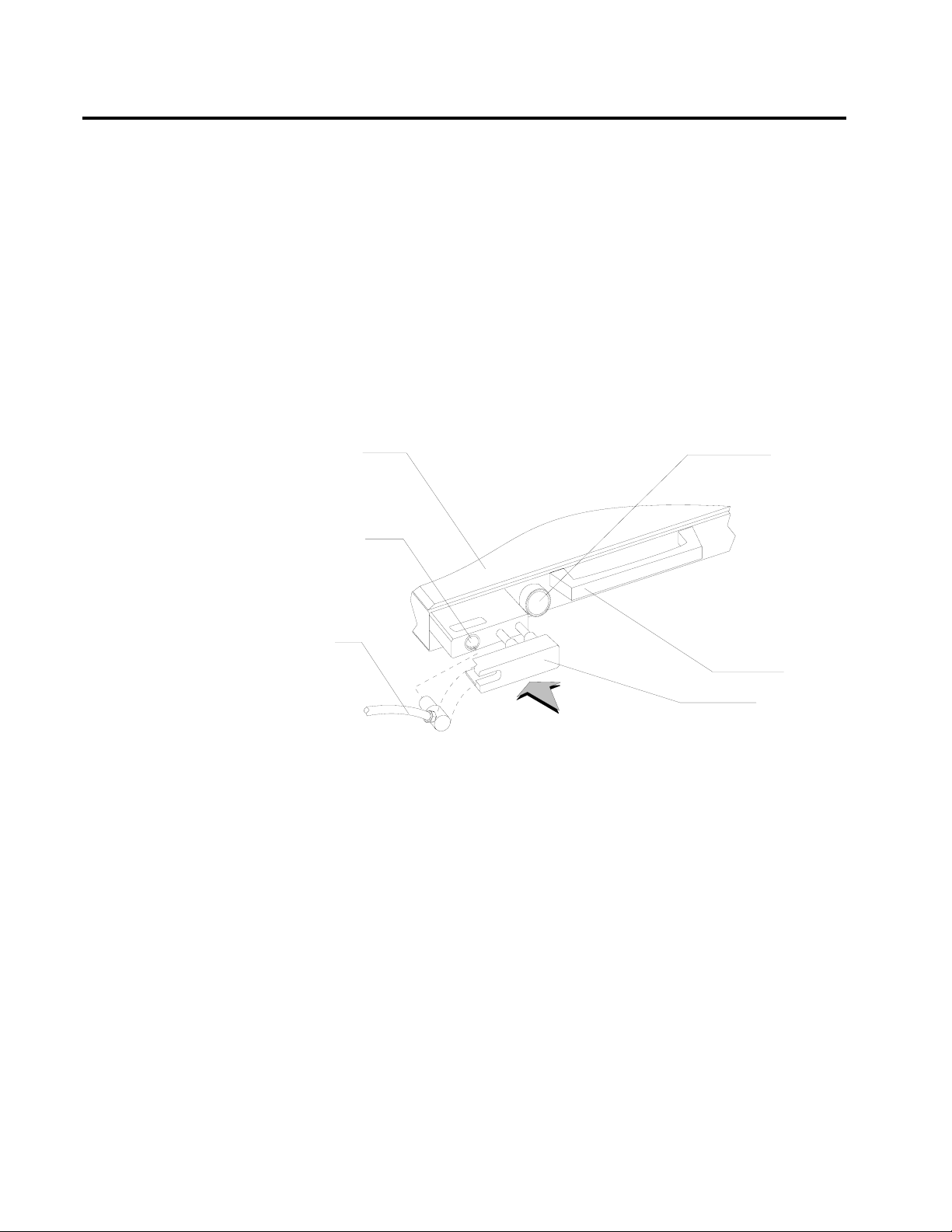
Fresh Gas Outlet
The fresh gas outlet delivers the fresh gas mixture (consisting of oxygen,
nitrous oxide, optional gases, and vapors of a liquid anesthetic) to the
patient breathing system. It is located on the front of the anesthesia
machine.
The outlet’s 15 mm cylindrical female fitting is designed to accept a
15 mm male fitting on the absorber fresh gas hose. The male fitting
slides into a retaining slot in the spring-loaded safety locking bar to
prevent inadvertent disconnection of the fresh gas hose. The 15 mm
male fitting on the fresh gas hose is unique to North American Dräger
design, and should not be replaced by a hose from any other
manufacturer.
TABLETOP
FRESH GAS
OUTLET
O2 FLUSH
CONTROL
FRESH
GAS
HOSE
OP10011
RELEASE TO
L
K
HANDLE
FRESH GAS
LOCKING BAR
EXTENDED POSITION
2-8
Page 21
RETURN TO CD-ROM TABLE OF CONTENTS
Section 2
General Description
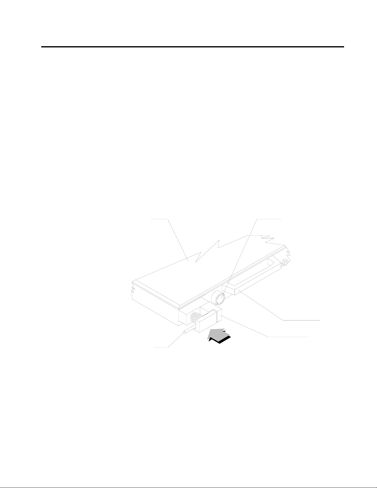
Fresh Gas Outlet
(Canada)
The fresh gas outlet delivers the fresh gas mixture (consisting of oxygen,
nitrous oxide, optional gases, and vapors of a liquid anesthetic) to the
patient breathing system. It is located on the front of the anesthesia
machine.
The outlet has a dual fitting for using gas hoses with these fittings:
• a 15 mm male fresh gas hose fitting, such as those supplied with
North American Dräger absorbers and Bain circuit adapters.
When using a 15 mm fitting, place the spring-loaded locking bar
over the male fitting to secure it to the female fitting.
• a 22 mm female fitting with a load-bearing threaded mount, such
as the ones for Magill circuits or ISO-type nonrebreathing
adapters. When using an ISO-type nonrebreathing adapter,
swing the spring-loaded locking bar to the side to gain access to
the threaded load-bearing fitting.
TABLETOP
O2 FLUSH CONTROL
FRESH GAS
HOSE
RELEASE TO
LOCK
HANDLE
FRESH GAS
LOCKING BAR
OP10012
2-9
Page 22
Section 2
General Description
RETURN TO CD-ROM TABLE OF CONTENTS
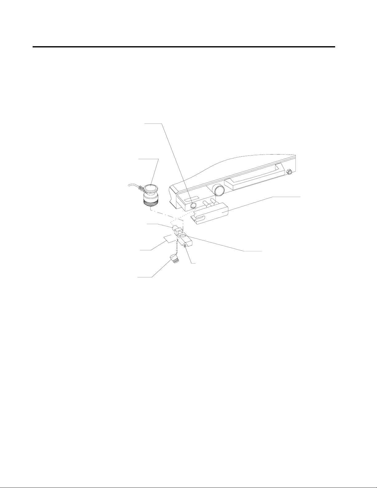
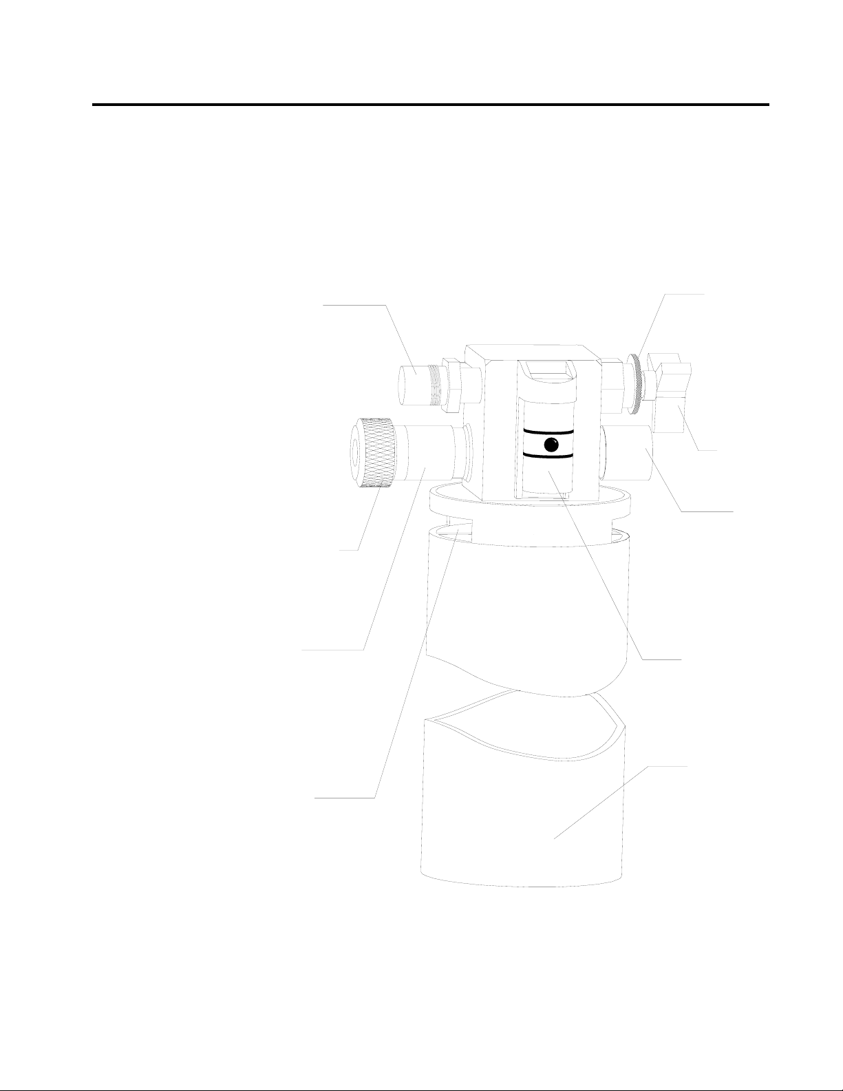
Fresh Gas Oxygen
Sensor Adapter
The optional fresh gas adapter allows the Narkomed 2C to monitor the
fresh gas oxygen concentration when using a nonrebreathing circuit
(other than a Bain circuit). The fresh gas adapter fits securely into the
fresh gas outlet of the anesthesia machine. It has a port for an oxygen
analyzer sensor and a fitting for a nonrebreathing circuit.
FRESH GAS
OUTLET
OXYGEN
SENSOR
FRESH GAS
LOCKING BAR
(EXTENDED POSITION)
15MM MALE
FITTING
ADAPTER
STEM
OXYGEN
SENSOR PLUG
OP20997
FRESH G A S HOSE
BARBED FITTING FOR
NON-REBREATHING
GAS CIRCUIT
OXYGEN SENSOR PORT
WARNING: The fresh gas oxygen sensor adapter measures the fresh
gas oxygen concentration, not the inspiratory oxygen
concentration. Depending on the fresh gas flow and the
respiratory minute volume, the inspiratory oxygen
concentration may be lower than fresh gas oxygen
concentration due to rebreathing of previously exhaled
gases.
2-10
Page 23
RETURN TO CD-ROM TABLE OF CONTENTS
Section 2
General Description
Auxiliary Oxygen
Flowmeter (Optional)
Vaporizers
Exclusion System
Filling Systems
For the delivery of a metered flow of pure oxygen (for example, delivery
of oxygen through a nasal cannula), an optional auxiliary oxygen
flowmeter can be mounted on the left side of the flowmeter bank. This
flowmeter can be used when the machine is turned off. A zero-stop
prevents damage to the flow control valve seat.
The Narkomed 2C can be equipped with up to three Vapor 19.1
vaporizers for administering liquid anesthetics.
A cam and lever interlock system, incorporated into the vaporizer bank,
prevents more than one vaporizer from being activated at a time. The
interlock system requires all unused vaporizers to be locked in their
zero-volume percent positions.
WARNING: Only one vaporizer can be activated at a time. If the
exclusion system permits simultaneous activation of more
than one vaporizer, do not use the anesthesia machine.
Contact a North American Dräger qualified technical
service representative for adjustment.
Two filling systems are available for the Vapor 19.1 vaporizer the open
funnel system and the key-indexed safety system.
OPEN FUNNEL FILLER
OP10603
KEY INDEXED
SAFETY SYSTEM
2-11
Page 24
Section 2
General Description
RETURN TO CD-ROM TABLE OF CONTENTS
Absorber
The absorber is a dual-canister system for absorbing exhaled carbon
dioxide in the rebreathing circuit of the anesthesia machine. It has an
adjustable pressure limiter (APL) valve, a breathing system pressure
gauge, a fresh gas line, and connections for sensing breathing pressure,
respiratory volume, frequency, and oxygen concentration.
OXYG EN SENSO R
INSPIRATORY
VALVE
RESPIRATORY VOLUM E SENSOR
(ULTRASONIC FLOW SENSO R)
EXPIRATORY VALVE
PEEP BYPASS
CONTROL
APL VALVE
PEEP VALVE
(O P T IO N A L )
ABSORBENT
CANISTER
FRESH G AS
HOSE
DUST CUP
O P 98103A
MANUAL/
AUTOM ATIC
SELECTOR
VALVE
BREATHING
SYSTEM
PRESSURE
GAUGE
BREATHING
BAG M OUNT
CANISTER RELEASE LEVER
2-12
Page 25

RETURN TO CD-ROM TABLE OF CONTENTS
Section 2
General Description
The absorber system permits spontaneous, manually assisted, or
automatic ventilation of the patient. The absorber incorporates a
manual/automatic selector valve, which allows you to select either
manual or automatic ventilation. An absorber with a positive endexpiratory pressure (PEEP) valve is also available.
WARNING: Waste gas scavenging systems used with North American
Dräger absorber systems must have safety features to
ensure that excessive subatmospheric pressure (lower than
-0.5 cmH
+0.5 cmH
O) and excessive positive pressure (higher than
2
O) are not possible at the connection point.
2
Inspiratory and
Expiratory Valves
The inspiratory and expiratory valves control the direction of gas flow in
the absorber system. The inspiratory valve is labeled INSPIRATION and
the expiratory valve is labeled EXPIRATION.
The valves are unidirectional, permitting gas flow in one direction only:
• The inspiratory valve allows gas to flow toward the patient only,
with no backflow to the absorber.
• The expiratory valve allows gas to flow into the absorber only,
with no backflow to the patient.
The valves are not interchangeable. They must be connected to the
correct mounts for proper flow direction through the absorber system.
Different size mounting threads on each valve prevent connecting a
valve to the wrong mount.
WARNING: Do not use the inspiratory or expiratory valves if:
• the pins in the plastic valve domes or in the valve
bodies are bent, damaged, or missing,
• valve disks are missing or damaged,
• valve seat is damaged.
2-13
Page 26

Section 2
General Description
RETURN TO CD-ROM TABLE OF CONTENTS
Canisters
Dust Cup
Breathing System
Pressure Gauge
Each absorber unit has two transparent plastic canisters that house the
absorbent. The absorbent soda lime or barium hydroxide lime can be
purchased in either loose granular or prepacked cartridge form. The
canisters are interchangeable.
A removable, transparent plastic cup below the bottom assembly collects
absorbent dust and excess moisture that could cause increased flow
resistance in the system.
The absorber system is equipped with a pressure gauge for quick visual
checks of breathing circuit pressure. The gauge is marked for
measurements from -20 to +80 cmH
O in increments of 2 cmH2O.
2
WARNING: You must frequently observe the breathing system
pressure gauge to ensure adequate pressure buildup and
relief, regardless of the mode of operation.
2-14
Page 27

RETURN TO CD-ROM TABLE OF CONTENTS
Section 2
General Description
Bain Circuit
Adapters
Absorber Mount
Two types of Bain circuit adapters are available. One mounts to the
absorber. The other mounts to the absorber pole.
The absorber-mounted Bain circuit adapter mounts on the
manual/automatic selector valve of the absorber system. The adapter has
an adjustable pressure limiter (APL) valve, a breathing pressure gauge,
a quick-connect fitting for the breathing pressure pilot line, a port for
the oxygen sensor, a 15/22 mm port for nonrebreathing circuits, and a
connector for the breathing bag.
APL VALVE
CONTROL KNOB
OXYG EN
SENSO R
22M M
M/15MM F
EXPIRATIO N
TER M IN A L
BREATHING PRESSURE
PILO T LIN E
Q U IC K -C O N N E C T F IT T IN G
BAIN
CIRCUIT
BAIN CIRCUIT
HO SE BARB FOR
FRESH G AS HO SE
BREATHING
BAG
FRESH G AS
HOSE
O P 21036
BREATHING
PRESSURE G AUG E
MANUAL/AUTOM ATIC
SELECTOR VALVE
OXYG EN SENSO R
PORT CAP
2-15
Page 28
Section 2
General Description
RETURN TO CD-ROM TABLE OF CONTENTS
Pole Mount
The pole-mounted Bain circuit adapter mounts on the absorber pole. A
positive end-expiratory pressure (PEEP) valve is optional.
OXYG EN
SENSO R
BREATHING
PRESSURE
PILO T LIN E
BAIN
CIRCUIT
BAIN
CIRCUIT HOSE
BARB FOR FRESH
GAS HO SE
PEEP CO NTROL
KNO B (OPTIONAL)
PEEP BYPASS CO NTRO L
(O P T IO N A L )
BREATHING SYSTEM
PRESSURE G AUG E
19 MM SCAVENG ER
HOSE
22M M VENTILATO R
HO SE
MANUAL/AUTOMATIC
SELECTOR VALVE
APL VALVE
SET SCREW
MOUNTING
STUD
O-RING
ABSORBER POLE
FRESH G AS HOSE
BREATHING
BAG M OUNT
O P 00200
2-16
Page 29
RETURN TO CD-ROM TABLE OF CONTENTS
Section 2
General Description
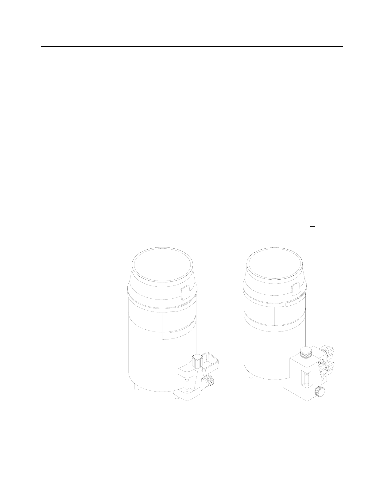
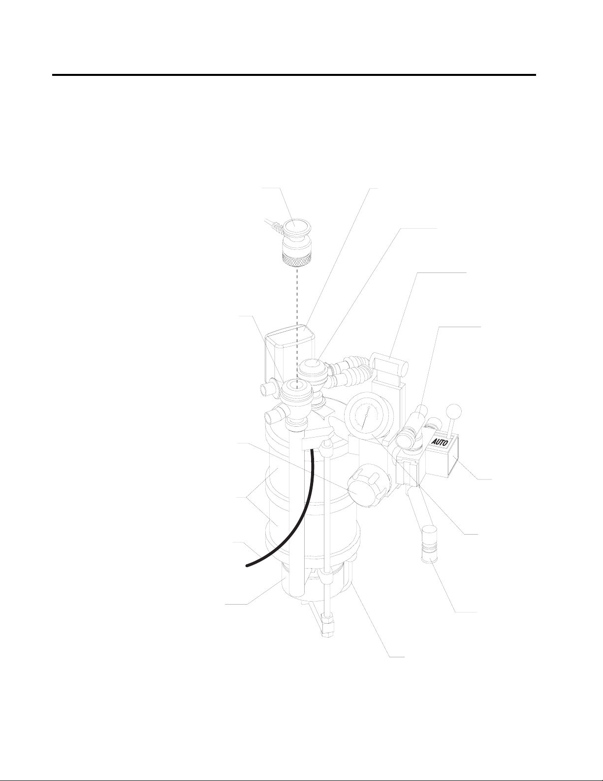
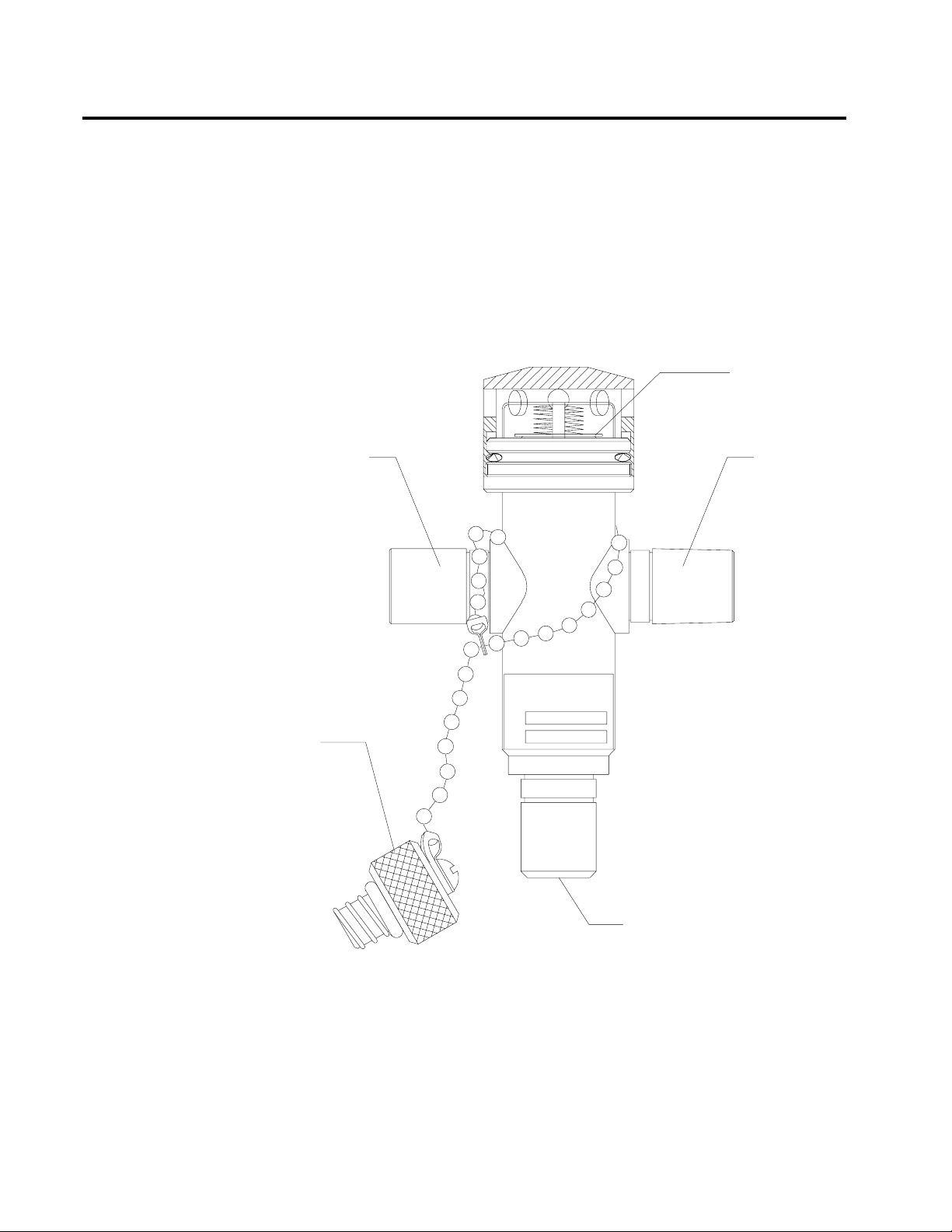
Scavenger Systems
Open Reservoir
Scavenger
The Narkomed 2C can be equipped with two kinds of scavenger systems,
for the best match with the hospital’s waste gas disposal system.
The open reservoir scavenger is used with suction (vacuum) waste gas
disposal systems. This scavenger is an “open” system with continually
open ports for positive and negative pressure control.
LOCK NUT
VACUUM
DISS HOSE
TERMINAL
NEEDLE
VALVE KNOB
19MM
SCAVENGER
HOSE TERMINAL
THREADED
INPUT
PORT CAP
19MM
SCAVENGER
HOSE TERMINAL
RELIEF
PORT
OP75121
FLOWMETER
RESERVOIR
CANISTER
2-17
Page 30
Section 2
General Description
RETURN TO CD-ROM TABLE OF CONTENTS
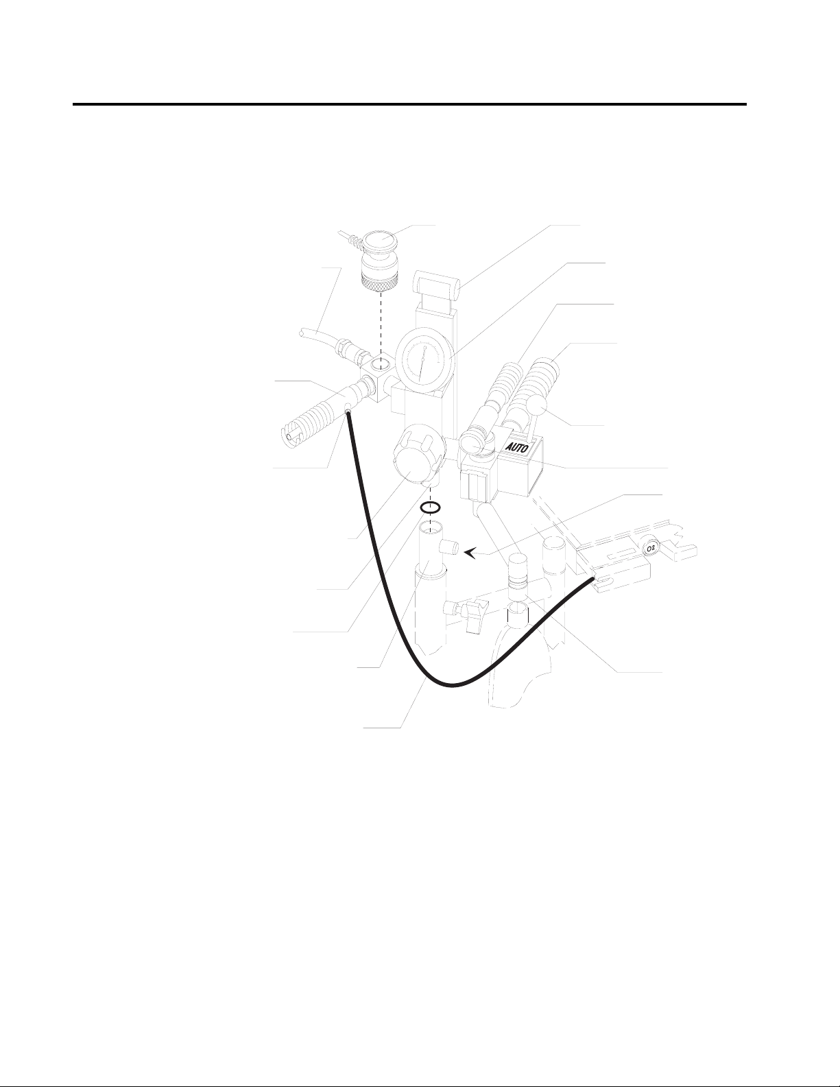
Scavenger Interface
for Passive Systems
The scavenger interface for passive systems is used with
nonrecirculating HVAC systems (also called exhaust systems). This
scavenger is a “closed” system with a spring-loaded valve for positive
pressure relief.
WARNING: Do not use this device with a waste gas disposal system
capable of applying a negative pressure to the scavenger
interface (a suction or vacuum waste gas disposal system).
SAFETY RELIEF
VALVE, SHOWN
CLOSED
WASTE GAS
INPUT PORT,
19MM HOSE
TERMINAL
WASTE GAS
INPUT PORT,
19MM HOSE
TERMINAL
2-18
INPUT
PORT CAP
OP76131
WASTE GAS EXHAUST PORT,
19MM HOSE TERMINAL
Page 31

RETURN TO CD-ROM TABLE OF CONTENTS
Section 2
General Description
AV2+ Ventilator
The AV2+ anesthesia ventilator is a volume-preset, time-cycled,
pressure-limited ventilator with electronic timing, pneumatic circuitry
and independent controls for frequency, inspiratory to expiratory (I:E)
ratio, inspiratory flow rate, tidal volume, and inspiratory pressure limit.
Pneumatic power (bellows drive gas) to the ventilator is supplied
through the hospital pipeline supply or through reserve cylinders on the
anesthesia machine. The pressure of the supply gas must be between 40
and 60 psi. The ventilator will not function properly if this pressure
drops below 32 psi. Electrical power is supplied by the AC power source.
In event of AC power failure, the backup battery supplies power. A fully
charged battery can power the ventilator for about 30 minutes.
The anesthesia ventilator is designed for use with a North American
Dräger absorber system that has a manual/automatic selector valve. Use
this valve to select the breathing bag and adjustable pressure limiter
(APL) valve for manual ventilation or the ventilator bellows for
automatic ventilation.
During automatic ventilation, the manual/automatic selector valve
isolates the absorber’s APL valve from the breathing system. The
ventilator has a relief valve mounted behind the bellows chamber to
compensate for the continuous introduction of fresh gas into the
breathing system.
When the bellows is completely filled, any excess gas in the system is
released to the scavenging system through the ventilator relief valve. As
in any ascending bellows, the force needed to overcome gravity acting on
the bellows causes a positive end-expiratory pressure (PEEP) within the
breathing system. The PEEP is about 2 cmH
2
O.
The pressure-limit control is used to set the peak inspiratory pressure
produced by the ventilator to prevent barotrauma. The pressure-limit
control can also improve ventilation for patients with reduced lung
compliance (neonatal/pediatric patients and patients with adult
respiratory distress syndrome), because it limits the peak inspiratory
pressure during the inspiratory phase of ventilation.
The AV2+ ventilator is shown in the following drawing.
2-19
Page 32

Section 2
General Description
RETURN TO CD-ROM TABLE OF CONTENTS
I:E RATIO CONTROL
EXTENDED RANGE
ACCESS
I:E RATIO DISPLAY
FREQUENCY
CONTROL
FREQUENCY
DISPLAY
10
FREQUENCY
/min
AV2+
INSPIRATORY PRESSURE LIMIT
cmH2O
1:2.5
I:E RATIO
EXTENDED
RANGE
TIDAL VOLUME
PUSH TO TURN
PRESET TIDAL VOLUME (ml)
1400
1200
1000
800
600
400
200
INSPIRATORY FLOW GAUGE
INSPIRATORY
FLOW CONTROL
VENTILATOR
ON-OFF
CONTROL
INSPIRATORY
FLOW
VENTILATOR
ON
FAULT
TIDAL VOLUME
CONTROL
PRESSURE
LIMIT CONTROL
Main Switch Panel
System Power Switch
AC Power Failure
Indicator
TIDAL
BELLOWS CANISTER
VOLUME
SETTING INDICATOR
OP91018c
BREATHING CIRCUIT
CONNECTOR
The main switch panel is located between the ventilator bellows and
flowmeter bank.
The SYSTEM POWER switch has two positions ON and STANDBY.In
the ON position, the gas (pneumatic) and electric power circuits are on.
The green indicator next to the switch lights. In the STANDBY position,
the switch shuts down the gas supplies, the monitoring system, and all
electrical power to the machine except the convenience receptacles and
battery charging circuit.
The yellow AC POWER FAIL indicator signals an AC power disruption.
The indicator lights whenever the battery supplies power to the
monitoring system and the electronic ventilator. A three-pulse tone also
sounds every 30 seconds. If the backup battery is completely discharged,
the AC power failure indicator does not have power and will not
function.
2-20
Page 33

RETURN TO CD-ROM TABLE OF CONTENTS
Section 2
General Description
O SUPPLY PRE SSURE
2
RED O2 SUPPLY
PRESSURE
LOW INDICATOR
YELLOW AC
POWER FAIL
INDICATOR
YELLOW
BATTERY LOW
INDICATOR
GREEN
BATTERY TEST
INDICATOR
POWER FAILAC
LOWBATTERY
BATTERY TEST
ON
STAND BY
SYSTEM POWER
BATTERY
TEST PUSH
BUTTON
SYSTEM
POWER
SWITCH
OP20050
Oxygen Supply
Pressure Alarm
The oxygen supply pressure alarm activates if the oxygen supply
pressure in the system decreases below about 37 psi. When the alarm is
actuated, the red O
SUPPLY PRESSURE indicator lights continuously,
2
the Caution message O2SUPPLY LOW appears on the central alarm
display, and an intermittent audible alarm sounds. Depending on the
configuration, a 7-second whistle may also sound.
NOTE: The oxygen supply pressure alarm will not activate if only one
source of oxygen supply pressure (either the cylinder or the
pipeline) fails and the other maintains proper pressure in the
oxygen supply lines.
2-21
Page 34

Section 2
E
General Description
RETURN TO CD-ROM TABLE OF CONTENTS
Power Supply
System
Convenience
Receptacles
The Narkomed 2C has a central power supply for the ventilator, alarm
system, and monitoring system. When in use, the Narkomed 2C must be
plugged into an AC outlet.
The Narkomed 2C has four convenience receptacles located on the upper
back area of the anesthesia machine. (This option is not available for the
240 VAC power supply option). The receptacles are active whenever the
Narkomed 2C is plugged into an outlet, whether or not the machine is
turned on.
The total current for devices plugged into the receptacles must not
exceed 7 amps. A 7-amp circuit breaker protects the convenience
receptacle circuit. This circuit also has an EMI filter to minimize
interference from devices plugged into the convenience receptacles.
CAUTION: Devices plugged into the convenience receptacles
contribute to the anesthesia system’s total leakage current.
The total leakage current must not exceed 100 microamps.
CIRCUIT
BREAKER
Circuit Breakers
2-22
CONVENIENC
RECEPTACLES
OP21050
The electrical system has four magnetic circuit breakers to protect
machine functions primary AC power input, convenience receptacles,
and backup battery power.
Page 35

RETURN TO CD-ROM TABLE OF CONTENTS
Section 2
General Description
The three circuit breakers located on the lower (absorber) side of the
machine are for 117 volt input power, 240 volt input power and backup
battery power. The fourth circuit breaker is for the convenience
receptacles and is located next to the convenience receptacles.
When the plunger is flush with the surface of its base, the circuit
breaker is in its normal, closed position. A circuit breaker is open
(tripped) when its plunger extends beyond its base. If a breaker is
tripped, the cause must be found and corrected before using the
anesthesia system.
Backup Battery
System
Machine Functions
on Backup Battery
Power
The backup battery system consists of a rechargeable battery and a
built-in battery charging system.
Although most hospitals have emergency generators that provide
AC power when line power fails, a delay may occur before generator
power comes on. The backup battery system automatically provides
power during the period between line power failure and activation of the
hospital’s emergency generator. The backup battery also provides power
if the anesthesia machine’s power cord is accidentally unplugged during
a case.
When the hospital’s emergency generator comes online (or when a
disconnected power cord is reconnected), the Narkomed 2C automatically
switches back to AC power and recharges its battery. The battery
charging system charges the battery any time the power cord is
connected to an active AC power source. The charger can recharge a
fully discharged battery in about 12 hours.
If the machine is receiving AC power, but the battery voltage level is low
due to a problem with the battery charging circuit or similar hardware
malfunction, the Advisory message RESERVE BATT LOW appears on the
central alarm display.
If the hospital’s primary AC power fails, the backup battery system is
activated. If this happens, the following events occur:
• The yellow AC POWER FAIL indicator on the alarm panel comes
on.
• The Caution message AC POWER FAIL appears on the central
alarm display.
• A three-pulse pattern tone sounds every 30 seconds.
These alarms signify that about 30 minutes of backup battery power
remains from the time the alarm is activated if the battery is fully
charged. All monitoring functions continue to operate, using the battery
for power.
2-23
Page 36

Section 2
General Description
When the battery reserve approaches depletion after an AC power loss:
• The yellow BATTERY LOW indicator lights.
• The Caution message AC BATTERY FAIL appears on the central
These alarms signify that about 10 minutes of backup battery power
remain from the time the alarm was activated.
The gas supply system remains operative. Because the ventilator is inoperative when battery power is cut off, you must perform manual
ventilation by bag. The machine cannot provide monitoring or alarm
functions until AC power is restored.
RETURN TO CD-ROM TABLE OF CONTENTS
NOTE: The BATTERY LOW indicator only lights during an AC
power loss when battery reserves are low.
display.
System Interface
Panel
NOTE: If the power cord is not plugged into an active AC outlet for a
period of 30 days or more, the backup battery can be depleted.
Plugging the power cord into an active AC outlet for about 12
hours recharges the battery.
The system interface panel is located on the absorber side of the
Narkomed 2C. The interface panel has receptacles for the oxygen sensor
cord, the breathing pressure pilot line, the respiratory volume sensor
cord, and the manual/automatic selector valve interface cable.
IN T E R F A C E
PANEL
RESPIRATORY
VOLUM E
MONITOR
IN T E R F A C E
MANUAL/
AUTOM ATIC
SELECTOR VALVE
IN T E R F A C E
OXYGEN
SEN SO R
VOLUM E
SEN SO R
BREATHING
PRESSURE
OXYG EN
ANALYZER
IN T E R F A C E
BREATHING
PRESSURE
MONITOR
IN T E R F A C E
SELECT OR
2-24
O P 21042
Page 37

RETURN TO CD-ROM TABLE OF CONTENTS
Section 2
General Description
Adjustable Display
Arm
Monitoring System
Narkomed 2C
Screens
The adjustable display arm, mounted on the absorber side of the
machine, supports the remote display and Datagrip. It is also used to
route patient sensor lines from the patient to the anesthesia machine.
The arm can be adjusted up and down, side-to-side, and front-to-back, to
place the display and sensor lines in the most convenient position. To
adjust the arm front-to-back, pull and hold the release knob forward,
then move the arm to the preferred position and release the knob.
The monitoring system integrates the electronic monitors and organizes
information from these monitors on the screen. The screen is mounted
on the adjustable display arm.
The Narkomed 2C monitors:
• oxygen concentration measurements
• breathing pressure measurements
• respiratory volume measurements
It also monitors key anesthesia system functions such as oxygen supply
pressure and backup battery status.
The Narkomed 2C has several screens for viewing monitoring
information, adjusting alarms, and customizing the monitoring system.
The screens include:
• Machine Monitor
• System Monitor
• Set Up
• System Configuration
• Data Log
• Data Management
The screens are accessed from a Screen Selection menu. They are
described in detail in the Section 5 Operation - Monitoring System
“Using the Screen Selection Menu.”
2-25
Page 38

Section 2
General Description
RETURN TO CD-ROM TABLE OF CONTENTS
Display Screen
All numerical data, waveforms, trends and alarms appear on the display
screen that is mounted on the display arm. The screen can be tilted up,
down, and sideways for optimal viewing.
DISPLAY ARM
O2
43
PEAK
43
MEAN
10
PEEP
2
MIN
VOL
7.50
TID
VOL
0.75
RR
10
8:30 9:30
WARNING
VENT PRES HI
CAUTION
O2 SUPPLY LOW
MINUTE VOLUME LOW
ADVISORY
NIBP STAT MODE
THRESHOLD LOW
RESERVE BATT LOW
8:43
VENT
SET UP
SCROLL
TREND
CLEAR TREND
CAL O
2
P
THRES
ORDM
VENT
NIBP
PRES
FLOW
AGT
SPO
SET
VENTILATION
ALARMS OFF
AUTOSET
LOG
CO
2
2
OP10757
THUMBWHEEL
DATAGRIP
Control Key Panel
DISPLAY
SCREEN
CONTROL
KEY PANEL
Each of the Control Key Panel keys, located on the right side of the
screen, performs a system function:
Silences the continuous audible alarm for 120 seconds. A
message indicating the number of seconds remaining in
the silence period is displayed in the Advisories window on
the central alarm display. If a new alarm occurs during
the 120 seconds, a single tone pattern sounds according to
the alarm priority. After 120 seconds, the audible alarm
reverts to normal operation if no alarm conditions are
active at that time.
If any Warning or Caution alarms are active at 120
seconds, the Narkomed 2C enters an extended silence
period and a single tone pattern sounds according to the
alarm priority. If a new alarm condition occurs during the
extended silence period, a single tone pattern sounds. Also,
at each one-minute interval of the extended silence period,
the highest-priority alarm tone pattern sounds.
2-26
Page 39

VENTILATION
ALARMS OFF
AUTOSET
RETURN TO CD-ROM TABLE OF CONTENTS
Section 2
General Description
The silence period can last up to three minutes. The
silence period ends if the Narkomed 2C is clear of
Warnings and Cautions for 10 seconds. When the extended
silence period ends, audio alarms revert to normal
operation.
Turns off volume and pressure-apnea alarms. If the
ventilator is on, the volume alarms are turned off, but the
pressure-apnea alarm remains on.
Function depends on the Datascan Display setting in the
System Configure screen.
If the Bar Graph Datascan is selected, pressing the
AUTOSET key sets the current measurements at the
center line of the Datascan display and resets the
endpoints. (See “Bar Graph Datascan Display” presented
later in this section.
Datagrip
If the Numeric Datascan is selected, pressing the
AUTOSET key resets the alarm limits according to the O2
ALARM AUTOSET value (WIDE, NARROW,orOFF) set in
the System Configure screen. If the Narkomed 2C is
connected to a Vitalert monitor with Alarm Autoset
capability, pressing the AUTOSET key also resets the
alarm limits on the Vitalert monitor.
For complete information on selecting the Datascan
display and setting the O2 ALARM AUTOSET value, see
Section 5 Operation - Monitoring System “Invoking the
System Configure Screen.”
The Datagrip is the user input device. The Datagrip is composed of a
trigger and thumbwheel attached to the display arm, next to the screen.
It can be tilted up and down for convenience and comfort.
Rotate the Datagrip thumbwheel to move the cursor around in screens,
change variables, and scroll through menus, lists, and trends. Rotating
the thumbwheel upward moves the cursor forward in a screen or list and
increases numbers. Rotating the thumbwheel downward moves the
cursor backward in a screen or list and decreases numbers.
Press the Datagrip trigger to invoke screens, choose parameters, enter
new values, and select soft keys that appear on the display screen.
2-27
Page 40

Section 2
General Description
An instructional dialog box, located in the lower right corner of certain
screens, guides you through the functions performed by Datagrip’s
trigger and thumbwheel for that specific screen. In the dialog box, the
icon indicates the function performed by rotating the thumbwheel.
The icon indicates the function performed by pressing the Datagrip
trigger.
RETURN TO CD-ROM TABLE OF CONTENTS
Datascan Display
Bar Graph Datascan
Display
The Datascan display is located at the top of the Data Log and System
Monitor screens. Information is presented in one of two display formats
the Bar Graph display or the Numeric display. The display format is
selected in the System Configure screen. (See Section 5 Operation -
Monitoring System “Invoking the System Configure Screen.”)
The Bar Graph Datascan display shows of six bar graphs that appear at
the top of the System Monitor screens. Use the Bar Graph Datascan to
see measurement deviations from a baseline. If information for one or
more bar graphs is not supplied, the corresponding display area is blank.
The six bar graphs include:
• end-tidal carbon dioxide
• inspiratory/expiratory anesthetic agent
• inspiratory oxygen concentration
• oxygen saturation
• pulse rate
• systolic/diastolic blood pressure
NOTE: The inspiratory agent and the systolic pressure measurements
are the larger numbers located below their respective bar
graphs.
2-28
A baseline measurement setpoint appears at the midpoint of each bar
graph, represented by a center line common to all six bar graphs.
Pointers along the left side of each bar graph mark the high and low
alarm limits. The current value for the measurement appears in
numerical form under each bar graph.
Any increase in a patient measurement causes the corresponding bar to
rise from the center line. If any patient measurement decreases, its bar
descends below the center line. Any deviation from the baseline whether
positive or negative is immediately apparent.
Page 41

OP27113
CO2 O2 SPO2 PLS NIBPISO
99
124
703943
70
1.5
1.0
RETURN TO CD-ROM TABLE OF CONTENTS
Section 2
General Description
Numeric Datascan
Display
To normalize the current measurements of the Narkomed 2C, press the
AUTOSET key on the control key panel. This sets the current
measurements at the center line (baseline) and resets the endpoints.
The endpoints of the bar graph boundaries represent values above and
below the baseline determined by the scaling factor set in the Datascan
Configure screen.
The Numeric Datascan displays current values for all patient
measurements and shows where those values are in relationship to the
current alarm limits. The Numeric Datascan consists of six rectangular
display areas for:
• end-tidal carbon dioxide
• inspiratory and expiratory anesthetic agent
• inspiratory oxygen concentration
• oxygen saturation
• pulse rate
• systolic and diastolic blood pressure
If information for one or more measurements is not supplied, the
corresponding display area is blank.
The current values for the measurement are the large numbers located
in the middle of each display area. The numbers at the top and bottom
are the current alarm limits. The arrow on the left side of each display
area shows where the current value lies within the boundaries of the
alarm limits. This arrow moves move up or down as the values change.
2-29
Page 42

Section 2
General Description
RETURN TO CD-ROM TABLE OF CONTENTS
Central Alarm
Display and Audible
Alarms
CO
50
ISO SPO2PLS
2
3.0
O
2
I
100
100
100
2.3
43
20
NOTE: The inspiratory agent and the systolic pressure measurements
also appear in the display areas.
To automatically adjust the alarm limits around the current values,
press the AUTOSET key on the control key panel. This sets the oxygen
alarm limits according to the O2 ALARM AUTOSET value specified in
the System Configure screen. For complete information, see Section 5
Operation - Monitoring System “Invoking the System Configure Screen”.
If the Narkomed 2C is connected to a Vitalert monitor with Alarm
Autoset capability, pressing the AUTOSET key also resets the alarm
limits for the monitoring functions provided by the Vitalert monitor.
The Narkomed 2C presents active alarms on the central alarm display
located at the top of the display screen. Alarms are indicated with
keyword phrases and are organized into three categories, depending on
their urgency. Alarms are displayed either in a single window or in three
separate windows corresponding to each alarm category.
1.7
E
1.0
39
18
100
85
65
50
NIBP
150
124
85
100
OP21010
2-30
A central speaker produces all audible alarm signals, using three
different sound patterns to indicate the three levels of alarm urgency.
The Narkomed 2C annunciates only the highest-priority, currently active
alarm. Lower-priority alarms are temporarily suppressed to minimize
the confusion caused by simultaneous alarms. If the primary speaker on
the Narkomed 2C fails, the Advisory message SERVICE SPEAKER
appears on the central alarm display and a single tone sounds.
If the number of alarms in any of the three categories exceeds the space
provided on the display screen for that category, additional alarm
messages are retained in memory until displayed alarm conditions are
resolved.
Page 43

RETURN TO CD-ROM TABLE OF CONTENTS
Section 2
General Description
Warnings
Warnings are the highest priority alarms and require an immediate
response.
If the Bar Graph Datascan is selected, Warnings appear in a drop-down
window in the upper left portion of the System Monitor screens,
overlaying the Datascan bar graphs. If no Warning alarm conditions
exist, the display is suppressed until an alarm condition occurs. Up to
seven Warnings can appear in this window.
If the Numeric Datascan is selected, Warnings appear in the single
alarm window in top right corner of the Machine Monitor screen and the
System Monitor screens, along with any Caution or Advisory messages.
The Warning messages are displayed under a flashing heading labeled
WARNING, which is removed from the screen if no Warning alarm
conditions exist. The last space at the bottom of the alarm window is
reserved for the SILENCE message that indicates the time remaining in
the Audio Silence period.
Warnings are announced with a continuously repeating sound pattern
consisting of three audio tones. After an initial sound pattern at full
volume, there is a 6-second pause. This pause is followed by a pattern at
one-third volume, a 5-second pause, a pattern at two-thirds volume, a 4second pause, and another pattern at full volume. After the second full
volume pattern, a 3-second pause occurs, followed by a full volume
pattern until the alarm condition is removed.
Cautions
Cautions are second-priority alarms and require a prompt response.
If the Bar Graph Datascan is selected, Cautions appear in a drop-down
window in the upper middle portion of the System Monitor screens,
overlaying the Datascan bar graphs. If no Caution alarm conditions
exist, the display is suppressed until an alarm condition occurs. Up to
seven Cautions can appear in this window.
If the Numeric Datascan is selected, Cautions appear in the single alarm
window in top right corner of the Machine Monitor screen and the
System Monitor screens, along with any Warning or Advisory messages.
The Caution messages are displayed under a heading labeled CAUTION,
which is removed from the screen if no Caution alarm conditions exist or
if all space in the alarm window is needed by the higher-priority
Warning messages.
2-31
Page 44

Section 2
General Description
The last space at the bottom of the alarm window is reserved for the
SILENCE message that indicates the time remaining in the Audio
Silence period.
Cautions are accompanied by a three-pulse sound pattern that is
repeated every 30 seconds until the alarm condition is cleared.
RETURN TO CD-ROM TABLE OF CONTENTS
Advisories
Silencing Alarms
Advisories are the lowest priority alarms that do not require immediate
attention.
If the Bar Graph display is selected, Advisories appear in a display
window in the upper right portion of the screen. Up to nine Advisories
can appear in this window, in addition to the SILENCE message that
indicates the time remaining in the Audio Silence period. The SILENCE
message occupies the last place at the bottom of the Advisory window.
If the Numeric Datascan is selected, Advisories appear in a single
window in top right corner of the Machine Monitor screen and the
System Monitor screens, along with any Warning or Caution messages.
The Advisory messages appear under a heading labeled ADVISORY,
which is removed from the screen if all space in the alarm window is
needed by the higher-priority Warning or Caution messages. The last
space at the bottom of the alarm window is reserved for the SILENCE
message that indicates the time remaining in the Audio Silence period.
Depending on the urgency, advisories are accompanied by a single tone
sounds or no audible alarm is given.
To temporarily silence audible alarms, use the alarm silence key on the
control key panel (labeled with a crossed-out speaker).
Ventilation Alarms
2-32
When the system power switch is turned from STANDBY to ON, the
volume and pressure apnea alarms default to Standby to allow machine
setup without nuisance alarms. An interlock with the ventilator ensures
that when the ventilator is turned on, the alarms are enabled. The
alarms can also be enabled individually in the Set Up screen.
Page 45

RETURN TO CD-ROM TABLE OF CONTENTS
General Description
When the ventilator is turned off, the following events occur:
Section 2
Manual Sphygmomanometer
(optional)
O.R. Data Manager
(optional)
• If the pressure apnea threshold was greater than 15 cmH
the ventilator was turned off, the threshold setting is changed to
15 cmH
O. (If the pressure apnea threshold was less than 15 cmH2O
2
when the ventilator was turned off, the threshold retains its setting.)
• The Cautions and Warnings associated with apnea alarms change
from activation after 15 and 30 seconds of apnea to 30 and 60
seconds, respectively.
When the ventilator is turned back on, the pressure apnea threshold is
restored to its previous set value and the apnea alarms revert to
activation after 15 seconds (caution) and 30 seconds (warning) of apnea.
Noninvasive blood pressure can be measured with the manual
sphygmomanometer. Several cuff sizes are available.
®
The O.R. Data Manager is an electronic data management system for
acquiring, storing, and retrieving information. It consists of a central
processing unit with disk drive and a keyboard for entering and editing
data. The O.R. Data Manager creates an electronic anesthesia record
from information automatically recorded by the monitoring system and
from input from the keyboard (such as patient data, events, drugs, and
other case-related information), and interfaced monitors such as the
®
Vitalert
3000.
O when
2
In addition to creating anesthesia records, the O.R. Data Manager can
graphically display case information and send anesthesia records to a
disk or laser printer.
2-33
Page 46

RETURN TO CD-ROM TABLE OF CONTENTS
Page 47

RETURN TO CD-ROM TABLE OF CONTENTS
Section 3
Daily Checkout
Daily Checkout
Procedure
Initial Setup and
Verification
Before operating the Narkomed 2C, the following checkout procedure
must be performed to make sure the machine is ready for use. This is a
recommended procedure. Follow your institution’s policies for specific
checkout procedures. If the anesthesia system fails any procedures
identified by an asterisk (*), do not use the machine. Contact a North
American Dräger qualified technical service representative for inspection
of the unit.
NOTE: Do not insert any additional components into, or modify,
the anesthesia system after the checkout procedure is
started.
1. Enter the serial number located on the right rear leg into the
anesthesia record.
2. Make sure there is a valid inspection sticker on the back of the
machine indicating that the anesthesia machine was serviced and
inspected by a North American Dräger qualified technical service
representative.
3. Verify that a cylinder wrench is tethered to the back of the
machine next to one of the cylinders.
System Software
Diagnostics
Battery Power
Verification
4. If the anesthesia machine is not already plugged in, connect the
electrical power cable to an active AC outlet that accepts and
properly grounds the power cable. Do not use “cheater” plugs.
The term “cheater” plug implies any and all electrical plugs or
other devices that can inhibit or prohibit the proper grounding of
the anesthesia machine.
*5. Turn the SYSTEM POWER switch to the ON position. Wait for
the machine to complete its diagnostic checks. Make sure the
system is functional.
*6. Check the reserve battery power. Remove the power plug from
the outlet. Press the BATTERY TEST button on the main switch
panel. The green indicator to the left of the test button must
light. The yellow BATTERY LOW indicator must remain unlit.
Plug the power cable back into the electrical outlet.
NOTE: This test assumes that the anesthesia machine has been
plugged in for 12 hours. The battery charging system
works only when the machine is connected to an active AC
power source. The charging system takes about 12 hours
to charge a fully discharged battery.
3-1
Page 48

Section 3
Daily Checkout
RETURN TO CD-ROM TABLE OF CONTENTS
Emergency
Ventilation Equipment
Verification
High Pressure
System Verification
*7. Verify that backup ventilation equipment is available and
functional.
*8. Check the oxygen cylinder supplies.
A. Disconnect all pipeline gas supply hoses and drain the
system.
B. Close the oxygen cylinder valve and remove the cylinder
from the yoke. Verify that there is one cylinder gasket and
there are two index pins. Verify that the cylinder matches
the yoke label. Place the cylinder back in its yoke.
C. Open an oxygen cylinder and check the cylinder pressure
gauge. A full oxygen cylinder registers about 1900 psi.
Replace any cylinder with pressure less than 1000 psi. To
check for a high pressure leak, close the cylinder and
observe the cylinder pressure gauge for a prominent
decrease in the pressure.
D. If the machine is equipped with dual oxygen yokes, repeat
these procedures for the other cylinder yoke.
*9. Check the nitrous oxide cylinder supplies.
A. Close the nitrous oxide cylinder valve and remove the
cylinder from the yoke. Verify that there is one cylinder
gasket and there are two index pins. Verify that the
cylinder matches the yoke label. Place the cylinder back in
its yoke.
B. Open the nitrous oxide flow control valve until the nitrous
oxide pipeline and cylinder pressure gauges indicate zero
pressure. Open a nitrous oxide cylinder and check the
cylinder pressure gauge. A full nitrous oxide cylinder
registers about 745 psi. Replace any cylinder with a
pressure less than 600 psi. To check for a high pressure
leak, close the cylinder and observe the cylinder pressure
gauge for a prominent decrease in the pressure.
C. If the machine is equipped with dual nitrous oxide cylinder
yokes, repeat these procedures for the other cylinder yoke.
3-2
Page 49

RETURN TO CD-ROM TABLE OF CONTENTS
Daily Checkout
*10. Check additional (optional) gas cylinder supplies.
A. With the cylinder closed, open the flow control valve of the
associated gas until the cylinder and pipeline pressure
gauges (air only) indicate zero pressure.
B. Close the cylinder valve and remove the cylinder from the
yoke. Verify that there is one cylinder gasket and there
are two index pins. Verify that the cylinder matches the
associated yoke label. Place the cylinder back in its yoke.
C. Open the associated flow control valve until the cylinder
pressure gauges indicate zero pressure. Open the cylinder
and check the cylinder pressure gauge. Replace the
cylinder if its contents are insufficient for the intended
procedure. To check for a high pressure leak, close the
cylinder and observe the cylinder pressure gauge for a
prominent decrease in the pressure.
Section 3
NOTE: After testing all of the gas circuits, drain the oxygen
circuit by closing the oxygen cylinder and actuating the
oxygen flush button on the front of the anesthesia
machine. Hold the button in until the pressure gauges
indicate no pressure.
The following table shows the full and minimum pressures (E-size
cylinders at 70°F, 21°C) for all gases available for the anesthesia
machine.
GAS PSI - FULL
Air 1900 1000
Carbon Dioxide 838 600
Nitrous Oxide 745 600
Oxygen 1900 1000
*
PSI - MIN
*typical full load
3-3
Page 50

Section 3
Daily Checkout
RETURN TO CD-ROM TABLE OF CONTENTS
Pipeline Supply
System Verification
Low Pressure
System Verification
*11. Pipeline Supply Verification
A. Inspect the supply hoses for cracks or wear.
B. Connect the appropriate hospital pipeline supply hoses
from the wall outlet fittings to the pipeline inlet
connectors.
C. Check for sufficient pipeline pressure readings for each gas
on the pipeline pressure gauges located below the flow
control valves. The pressure for each gas must be between
50–55 psi. Open the flow control valve for each gas to a
moderate value. The pressure indicated at the pipeline
pressure gauge must not decrease more than 5 psi.
D. Verify that the correct gases are supplied to the anesthesia
machine inlets.
*12. Vaporizer Verification
A. Check for sufficient supply of liquid anesthetic in the
vaporizer(s). The liquid level indicated in the vaporizer
sight glass must be between the minimum and maximum
markings.
System Gas Circuit
Verification
Oxygen Monitor
Calibration
B. Make sure the fill and drain valves are completely closed.
C. Check the vaporizer exclusion device, which prevents more
than one vaporizer from being activated simultaneously.
Make sure that when one vaporizer handwheel is turned
to a setting greater than 0, the others remain locked in
their 0 positions. Test all of the vaporizer positions. Then,
turn all vaporizers to the 0 position.
*13. Check the flowmeters. Adjust the flow control knob for each gas
and verify the proper operation of the corresponding flowmeters.
The float must move freely over the full range of each flowmeter.
*14. Calibrate the oxygen monitor by exposing the sensor to ambient
air and activate the calibration key. (See Operation - Oxygen
Monitoring “Calibrating the Oxygen Sensor” in Section 5 for more
information.)
A. Place the oxygen sensor securely in the sensor mount.
B. Verify that the correct gas concentrations are supplied to
the anesthesia system from the supply cylinders.
3-4
Page 51

RETURN TO CD-ROM TABLE OF CONTENTS
Section 3
Daily Checkout
C. Close the cylinder supplies and deplete the pressure from
the system.
OFPD Verification
ORC Verification
Oxygen Flush
Verification
*15. Check the oxygen failure protection device. With all gases
available on the machine set to a flow of about 4 l/min, close the
oxygen supply by disconnecting the oxygen pipeline supply hose
and closing the oxygen cylinder(s). The flow of all other gases indicated by their flowmeters must decrease in proportion to the
decrease in oxygen flow and eventually shut off.
*16. Check the function of the ORC. With the nitrous oxide flow
control valve open to a flow of 10 l/min, vary the oxygen flow with
the oxygen flow control valve. The nitrous oxide flow indicated on
the nitrous oxide flowmeter must automatically vary in response
to the adjustment of the oxygen flow control valve.
The ORC must maintain a fresh gas oxygen/nitrous oxide flow
ratio of at least 25 ±4 % oxygen.
NOTE: When the nitrous oxide flow control valve is open
and oxygen is flowing at a minimum rate (150–200
ml/min), nitrous oxide flows at approximately 500
ml/min.
*17. Check the oxygen flush:
A. Press the oxygen flush button and listen for an audible gas
flow sound, accompanied by a marked increase in oxygen
concentration in the breathing system.
Fresh Gas
Verification
Bain Circuit Adapter
Verification
B. Check the delivered oxygen concentration. Repeatedly
flush the patient breathing system by pressing the oxygen
flush button. Open the oxygen flow control valve to a flow
of 8 l/min and close the other flow control valves. The
oxygen measurement display area should indicate 97% to
100% oxygen concentration.
*18. Make sure all vaporizers are closed. Open the oxygen flow control
valve to an 8 l/min flow and close all other flow control valves.
Sniff the gas coming from the fresh gas common outlet. There
should be no noticeable odor.
*19. Verify that the inner tube of the Bain circuit is intact and not
occluded. First deliver a flow of oxygen to the Bain circuit
through the fresh gas hose. Then occlude the inner tube of the
Bain circuit. The oxygen flowmeter float should drop in response
to the occlusion.
3-5
Page 52

Section 3
Daily Checkout
RETURN TO CD-ROM TABLE OF CONTENTS
As an alternate test, press the oxygen flush button with the Bain
circuit’s patient port open to the atmosphere. The high flow of gas
through the Bain circuit’s inner tube will draw in gas from the
outer tube. As a result, the breathing bag should deflate. If the
breathing bag does not deflate or it inflates, the fresh gas hose or
inner tube may be improperly connected.
Absorber System
Verification
*20. To check the absorber system:
A. Check the hose connections in the breathing system.
B. Make sure the fresh gas hose of the breathing system is
securely connected to the fresh gas outlet.
C. Make sure a 22 mm patient breathing circuit is connected
between the inspiratory valve and the expiratory hose
terminal on the ultrasonic flow sensor.
D. Make sure a 22 mm breathing hose is connected between
the ventilator hose terminal and the manual/automatic
selector valve breathing hose terminal.
E. Make sure a breathing bag of proper capacity and
appropriate construction is connected to the breathing bag
terminal of the breathing system.
F. Make sure the breathing pressure pilot line is properly
connected between the BREATHING PRESSURE interface
and either the absorber quick-connect fitting or the
appropriate fitting at or near the patient Y-piece.
3-6
G. Make sure the oxygen sensor and respiratory volume
sensor are properly installed.
*21. Make sure the absorber canisters are filled with CO
Consult the absorbent manufacturer’s literature for information
on what signs to expect when the absorbent is exhausted. Replace
the absorbent when it appears exhausted. Make sure that the
color change represents the absorbent’s true state of depletion
and is not due to regeneration after a rest period. Flushing the
anesthesia machine continuously with 100% oxygen for at least
one minute before the first case of the day is recommended.
Remove accumulated absorbent dust and water from the absorber
dust cup.
absorbent.
2
Page 53

RETURN TO CD-ROM TABLE OF CONTENTS
Section 3
Daily Checkout
WARNING: Absorbent is caustic and is a strong eye, skin, and
respiratory tract irritant. When emptying the
absorber dust cup, take care not to spill its caustic
contents.
APL Valve
NOTE: When changing the CO
absorbent, take care not to
2
chip or crack the absorbent canister. Check the
canister for signs of damage, especially along the
rim, before reinstallation.
22. Close all vaporizers and flow control valves. Check for free gas
passage in the patient breathing system. Wear a surgical mask to
inhale and exhale through the breathing system (each limb
individually, if possible). Verify the unidirectional flow in each
limb and then reconnect the tubing.
*23. Check the APL valve to be sure it can relieve excess gas from the
breathing system into the scavenger system.
To check the APL valve’s flow resistance:
A. Set the manual/automatic selector valve to BAG.
B. Remove the bag from the swivel arm bag mount.
C. Interconnect the inspiratory valve and the expiratory hose
terminal on the ultrasonic flow sensor with a 22 mm hose.
Breathing System
Leak Test
D. Completely open the APL valve by turning the control
knob fully counterclockwise to its stop position.
E. Turn the SYSTEM POWER switch to ON.
F. Open the oxygen flow control valve to a flow of 8 l/min.
G. Occlude the bag mount opening and watch for a pressure
increase on the breathing system pressure gauge. This
pressure increase must not exceed 3 cmH
O.
2
24. Perform a breathing and fresh gas delivery system pressure test.
This test detects leaks from the patient breathing system and
fresh gas delivery system.
To perform the test:
A. Close all flow control valves on the anesthesia machine.
3-7
Page 54

Section 3
Daily Checkout
RETURN TO CD-ROM TABLE OF CONTENTS
B. Turn the SYSTEM POWER switch to the STANDBY posi-
tion.
C. Turn the vaporizers to 0% concentration.
D. Interconnect the inspiratory valve and the expiratory hose
terminal on the ultrasonic flow sensor with a 22 mm
breathing hose.
E. Set the manual/automatic selector valve to BAG.
F. Close the APL valve by turning the knob fully clockwise to
its stop position.
G. Check that the breathing pressure gauge is on 0.
H. Attach the supplied test terminal to the breathing bag
mount.
Scavenger System
I. Connect a sphygmomanometer squeeze bulb (available
from North American Dräger) to the hose barb on the test
terminal.
J. Pump the squeeze bulb by hand until the breathing
system pressure gauge indicates pressure of at least 50
O (not to exceed 80 cmH2O).
cmH
2
K. Observe the pressure drop at the breathing system
pressure gauge. When the pressure is at 50 cmH
counting seconds. The pressure must not drop more than
20 cmH
O in 30 seconds.
2
*25. Verify the performance of the scavenger system.
To test the open reservoir scavenger system:
A. Make sure a 19 mm scavenger hose is connected between
the ventilator relief valve and the scavenger interface.
B. Make sure a 19 mm scavenger hose is connected between
the APL valve on the absorber and the 19 mm hose
terminal on the back of the absorber pole.
O, begin
2
3-8
C. Make sure a 19 mm scavenger hose is connected between
the bottom of the absorber pole and the scavenger
interface.
Page 55

RETURN TO CD-ROM TABLE OF CONTENTS
Section 3
Daily Checkout
D. Check for moisture accumulation in the breathing and
scavenger hoses. Remove any moisture found.
E. Verify the safe performance of the open reservoir
scavenging system. With the scavenging system properly
installed and operating, test for positive and negative
pressure relief.
To test for negative pressure relief:
F. Connect a vacuum hose to the DISS threaded terminal on
the left-hand side of the scavenger (or attach a wall
suction hose onto the adapter’s hose-barb fitting).
G. Short-circuit the inspiratory valve and the expiratory hose
terminal on the ultrasonic flow sensor with a 22 mm
breathing hose.
H. Set the absorber’s manual/automatic selector valve to BAG.
I. Turn the APL valve control knob fully counterclockwise.
J. Verify that the suction waste gas disposal system is active.
K. Adjust the scavenger needle valve to a flowmeter
indication between the two white lines.
L. Close all flow control valves on the anesthesia system.
M. Occlude the absorber breathing bag terminal and observe
the breathing pressure gauge on the absorber. The gauge
should indicate only a negligible negative pressure (no
lower than -0.5 cmH
2
O).
To test for positive pressure relief:
N. Perform steps A through E.
O. If the system is equipped with a PEEP valve, turn the
PEEP valve control knob fully counterclockwise to its
lowest setting.
P. Adjust the scavenger needle valve to a completely closed
position by turning it fully clockwise.
Q. Open the oxygen flow control valve to a flow of 10 l/min
and occlude the absorber breathing bag terminal.
3-9
Page 56

Section 3
Daily Checkout
RETURN TO CD-ROM TABLE OF CONTENTS
R. The flow of oxygen must now exit through the relief ports
located on top of the canister. The absorber system’s
breathing pressure gauge must indicate a pressure less
than5cmH
O.
2
S. After the test, adjust the scavenger needle valve to a
flowmeter indication halfway between the two white lines.
To test the scavenger interface for passive systems:
A. Make sure a 19 mm scavenger hose is connected between
the ventilator relief valve and the scavenger interface.
B. Make sure a 19 mm scavenger hose is connected between
the APL valve on the absorber and the 19 mm hose
terminal on the back of the absorber pole.
C. Make sure a 19 mm scavenger hose is connected between
the bottom of the absorber pole and the scavenger
interface.
D. Check for moisture accumulation in the breathing and
scavenger hoses. Remove any moisture found.
E. Short circuit the inspiratory valve and the expiratory hose
terminal on the ultrasonic flow sensor with a 22 mm
breathing hose.
F. Set the absorber’s manual/automatic selector valve to
AUTO.
G. If the system is equipped with a PEEP valve, turn the
PEEP valve control knob fully counterclockwise to its
lowest setting.
H. Open the oxygen flow control valve to a flow of 10 l/min
and occlude the 19 mm scavenger terminal labeled
EXHAUST.
I. After the ventilator bellows inflates, the flow of oxygen
exits the system through the positive pressure safety relief
valve. At this point, the absorber system’s breathing
pressure gauge must indicate a pressure of less than 10
O.
cmH
2
3-10
Page 57

RETURN TO CD-ROM TABLE OF CONTENTS
Section 3
Daily Checkout
Manual and
Automatic Ventilation
Systems
*26. Test the ventilator.
A. Check for proper pressure and flow at the Y-piece during
the inspiratory and expiratory phases. Turn the SYSTEM
POWER switch and ventilator power switch to their ON
positions. Place the manual/automatic selector valve in the
AUTO position. Adjust the oxygen flow control valve to a
3 l/min flow. Set the ventilator frequency to 3 BPM, the
I:E ratio to 1:2, and the tidal volume to about 1 liter. (If
testing the Pediatric Bellows or Adult/Pediatric Bellows,
adjust the tidal volume to 200 ml.)
Adjust the ventilator flow control to the maximum of the
“low” zone on the flow gauge. Occlude the patient side of
the Y-piece. Fill the ventilator bellows by pressing the
oxygen flush button. Observe the breathing system
pressure gauge as the ventilator cycles.
The pressure gauge must indicate a pressure over 30
O when the bellows completes its downward travel.
cmH
2
The pressure should not exceed 3 cmH
expiratory phase when the bellows completes its upward
travel.
O at the end of the
2
Monitors
B. If the system is equipped with a PEEP valve, verify the
PEEP valve’s performance. Attach a breathing bag to the
patient Y-piece with an appropriate adapter such as an
NAD combination mask elbow with a 22 mm male fitting
for the breathing bag and 15 mm male fitting for the
Y-piece. With the manual/automatic selector valve in the
AUTO position, set the ventilator to the preferred
frequency.
Then adjust the PEEP valve to different values and
observe the breathing system pressure gauge to verify
performance. Turn the PEEP valve control knob fully
counterclockwise to its lowest setting after the test is
completed. Set the PEEP bypass switch to the PEEP OFF
position.
27. Check the alarm limit settings. The monitor alarm limits are
automatically set to a default configuration when the SYSTEM
POWER switch is turned on. Check these settings and adjust
them if necessary. Alarm limits can be adjusted at the beginning
of or during a procedure. Also, make sure that any external
monitors (if any) are connected properly and that the alarms
sound through the anesthesia machine’s central audio
annunciator.
3-11
Page 58

Section 3
Daily Checkout
RETURN TO CD-ROM TABLE OF CONTENTS
*28. Test the alarm functions for all monitors. Simulate alarm
conditions and check for appropriate alarm signals.
System Flush
Fresh Gas Oxygen
Sensor Adapter
Option Verification
Final Position
29. Flush the system with 100% oxygen by pressing the oxygen flush
button.
30. If the optional fresh gas oxygen sensor adapter is installed, make
sure the fresh gas hose connection is intact and not occluded.
Verify that the oxygen analyzer is properly calibrated. (See
Operation - Oxygen Monitoring “Calibrating the Oxygen Sensor”
in Section 5 for more information.) When removing the oxygen
sensor during calibration, insert the oxygen sensor port plug into
the fresh gas adapter port.
31. When the daily checkout procedure is complete, verify that:
A. all vaporizers are off (the handwheels are set to zero)
B. the APL Valve is open (fully counterclockwise)
C. the manual/automatic switch is set to BAG
D. all flowmeters indicate 0 (or minimum)
E. the patient suction is level adequate
F. the breathing system is ready to use (the bag is in place
and all hoses are connected properly)
3-12
Page 59

RETURN TO CD-ROM TABLE OF CONTENTS
Section 4
Preuse Checkout
Preuse Checkout
Procedure
Reserve Power
Verification
Perform the following abbreviated checkout procedure when the
Narkomed 2C is used in successive cases. It may be performed only after
the initial daily checkout procedure given in Section 3 was performed.
This is a recommended procedure. Follow your institution’s policies
regarding specific checkout procedures. If the anesthesia system fails
any procedures identified by an asterisk (*), do not use the machine.
Contact a North American Dräger qualified technical service
representative for inspection of the unit.
NOTE: Do not insert any additional components into or modify the
anesthesia system after the checkout procedure is started.
*1. Check the reserve battery power. Make sure that the SYSTEM
POWER switch is turned to the ON position. Remove the power
plug from the outlet. Press the BATTERY TEST button on the
main switch panel. The green indicator to the left of the test
button must light. The yellow BATTERY LOW indicator must
remain unlit. Plug the power cable back into the electrical outlet.
NOTE: This test assumes that the anesthesia machine has been
plugged in for 12 hours. The battery charging system
works only when the machine is connected to an active AC
power source. The charging system takes about 12 hours
to charge a fully discharged battery.
Bain Circuit Adapter
Verification
Absorber System
Verification
*2. Verify that the inner tube of the Bain circuit is intact and not
occluded. First deliver a flow of oxygen to the Bain circuit
through the fresh gas hose. Then occlude the inner tube of the
Bain circuit. The oxygen flowmeter float should drop in response
to the occlusion.
As an alternate test, press the oxygen flush button with the Bain
circuit’s patient port open to the atmosphere. The high flow of gas
through the Bain circuit’s inner tube will draw in gas from the
outer tube. As a result, the breathing bag should deflate. If the
breathing bag does not deflate or it inflates, the fresh gas hose or
inner tube may be improperly connected.
*3. To check the absorber system:
A. Check the hose connections in the breathing system.
B. Make sure the fresh gas hose of the breathing system is
securely connected to the fresh gas outlet.
4-1
Page 60

Section 4
Preuse Checkout
RETURN TO CD-ROM TABLE OF CONTENTS
C. Make sure a 22 mm patient breathing circuit is connected
between the inspiratory valve and the expiratory hose
terminal on the ultrasonic flow sensor.
D. Make sure a 22 mm breathing hose is connected between
the ventilator hose terminal and the manual/automatic
selector valve breathing hose terminal.
E. Make sure a breathing bag of proper capacity and
appropriate construction is connected to the breathing bag
terminal of the breathing system.
F. Make sure the breathing pressure pilot line is properly
connected between the BREATHING PRESSURE interface
and either the absorber quick-connect fitting or the
appropriate fitting at or near the patient Y-piece.
G. Make sure the oxygen sensor and respiratory volume
sensor are properly installed.
*4. Make sure the absorber canisters are filled with CO
Consult the absorbent manufacturer’s literature for information
on what signs to expect when the absorbent is exhausted. Replace
the absorbent when it appears exhausted. Make sure that the
color change represents the absorbent’s true state of depletion
and is not due to regeneration after a rest period. Flushing the
anesthesia machine continuously with 100% oxygen for at least
one minute before the first case of the day is recommended.
Remove accumulated absorbent dust and water from the absorber
dust cup.
WARNING: Absorbent is caustic and is a strong eye, skin, and
respiratory tract irritant. When emptying the
absorber dust cup, take care not to spill its caustic
contents.
NOTE: When changing the CO
absorbent, take care not to
2
chip or crack the absorbent canister. Check the
canister for signs of damage, especially along the
rim, before reinstallation.
absorbent.
2
4-2
5. Close all vaporizers and flow control valves. Check for free gas
passage in the patient breathing system. Wear a surgical mask to
inhale and exhale through the breathing system (each limb
individually, if possible). Verify the unidirectional flow in each
limb and then reconnect the tubing.
Page 61

RETURN TO CD-ROM TABLE OF CONTENTS
Section 4
Preuse Checkout
APL Valve
*6. Check the APL valve to be sure it can relieve excess gas from the
breathing system into the scavenger system.
To check the APL valve’s flow resistance:
A. Set the manual/automatic selector valve to BAG.
B. Remove the bag from the swivel arm bag mount.
C. Interconnect the inspiratory valve and the expiratory hose
terminal on the ultrasonic flow sensor with a 22 mm hose.
D. Completely open the APL valve by turning the control
knob fully counterclockwise to its stop position.
E. Turn the SYSTEM POWER switch to ON.
F. Open the oxygen flow control valve to a flow of 8 l/min.
G. Occlude the bag mount opening and watch for a pressure
increase on the breathing system pressure gauge. This
pressure increase must not exceed 3 cmH
O.
2
Breathing System
Leak Test
7. Perform a breathing and fresh gas delivery system pressure test.
This test detects leaks from the patient breathing system and
fresh gas delivery system.
To perform the test:
A. Close all flow control valves on the anesthesia machine.
B. Turn the SYSTEM POWER switch to the STANDBY posi-
tion.
C. Turn the vaporizers to 0% concentration.
D. Interconnect the inspiratory valve and the expiratory hose
terminal on the ultrasonic flow sensor with a 22 mm
breathing hose.
E. Set the manual/automatic selector valve to BAG.
F. Close the APL valve by turning the knob fully clockwise to
its stop position.
G. Check that the breathing pressure gauge is on 0.
4-3
Page 62

Section 4
Preuse Checkout
RETURN TO CD-ROM TABLE OF CONTENTS
H. Attach the supplied test terminal to the breathing bag
mount.
I. Connect a sphygmomanometer squeeze bulb (available
from North American Dräger) to the hose barb on the test
terminal.
J. Pump the squeeze bulb by hand until the breathing
system pressure gauge indicates pressure of at least 50
O (not to exceed 80 cmH2O).
cmH
2
K. Observe the pressure drop at the breathing system
pressure gauge. When the pressure is at 50 cmH
O, begin
2
counting seconds. The pressure must not drop more than
20 cmH
O in 30 seconds.
2
Scavenger System
*8. Verify the performance of the scavenger system.
To test the open reservoir scavenger system:
A. Make sure a 19 mm scavenger hose is connected between
the ventilator relief valve and the scavenger interface.
B. Make sure a 19 mm scavenger hose is connected between
the APL valve on the absorber and the 19 mm hose
terminal on the back of the absorber pole.
C. Make sure a 19 mm scavenger hose is connected between
the bottom of the absorber pole and the scavenger
interface.
D. Check for moisture accumulation in the breathing and
scavenger hoses. Remove any moisture found.
E. Verify the safe performance of the open reservoir
scavenging system. With the scavenging system properly
installed and operating, test for positive and negative
pressure relief.
4-4
To test for negative pressure relief:
F. Connect a vacuum hose to the DISS threaded terminal on
the left-hand side of the scavenger (or attach a wall
suction hose onto the adapter’s hose-barb fitting).
Page 63

RETURN TO CD-ROM TABLE OF CONTENTS
Section 4
Preuse Checkout
G. Short-circuit the inspiratory valve and the expiratory hose
terminal on the ultrasonic flow sensor with a 22 mm
breathing hose.
H. Set the absorber’s manual/automatic selector valve to BAG.
I. Turn the APL valve control knob fully counterclockwise.
J. Verify that the suction waste gas disposal system is active.
K. Adjust the scavenger needle valve to a flowmeter
indication between the two white lines.
L. Close all flow control valves on the anesthesia system.
M. Occlude the absorber breathing bag terminal and observe
the breathing pressure gauge on the absorber. The gauge
should indicate only a negligible negative pressure (no
lower than -0.5 cmH
2
O).
To test for positive pressure relief:
N. Perform steps A through E.
O. If the system is equipped with a PEEP valve, turn the
PEEP valve control knob fully counterclockwise to its
lowest setting.
P. Adjust the scavenger needle valve to a completely closed
position by turning it fully clockwise.
Q. Open the oxygen flow control valve to a flow of 10 l/min
and occlude the absorber breathing bag terminal.
R. The flow of oxygen must now exit through the relief ports
located on top of the canister. The absorber system’s
breathing pressure gauge must indicate a pressure less
than5cmH
O.
2
S. After the test, adjust the scavenger needle valve to a
flowmeter indication halfway between the two white lines.
4-5
Page 64

Section 4
Preuse Checkout
RETURN TO CD-ROM TABLE OF CONTENTS
To test the scavenger interface for passive systems:
A. Make sure a 19 mm scavenger hose is connected between
the ventilator relief valve and the scavenger interface.
B. Make sure a 19 mm scavenger hose is connected between
the APL valve on the absorber and the 19 mm hose
terminal on the back of the absorber pole.
C. Make sure a 19 mm scavenger hose is connected between
the bottom of the absorber pole and the scavenger
interface.
D. Check for moisture accumulation in the breathing and
scavenger hoses. Remove any moisture found.
E. Short circuit the inspiratory valve and the expiratory hose
terminal on the ultrasonic flow sensor with a 22 mm
breathing hose.
Manual and
Automatic Ventilation
Systems
F. Set the absorber’s manual/automatic selector valve to
AUTO.
G. If the system is equipped with a PEEP valve, turn the
PEEP valve control knob fully counterclockwise to its
lowest setting.
H. Open the oxygen flow control valve to a flow of 10 l/min
and occlude the 19 mm scavenger terminal labeled
EXHAUST.
I. After the ventilator bellows inflates, the flow of oxygen
exits the system through the positive pressure safety relief
valve. At this point, the absorber system’s breathing
pressure gauge must indicate a pressure of less than 10
cmH
O.
2
*9. Test the ventilator.
A. Check for proper pressure and flow at the Y-piece during
the inspiratory and expiratory phases. Turn the SYSTEM
POWER switch and ventilator power switch to their ON
positions. Place the manual/automatic selector valve in the
AUTO position. Adjust the oxygen flow control valve to a
3 l/min flow. Set the ventilator frequency to 3 BPM, the
I:E ratio to 1:2, and the tidal volume to about 1 liter. (If
testing the Pediatric Bellows or Adult/Pediatric Bellows,
adjust the tidal volume to 200 ml.)
4-6
Page 65

RETURN TO CD-ROM TABLE OF CONTENTS
Section 4
Preuse Checkout
Adjust the ventilator flow control to the maximum of the
“low” zone on the flow gauge. Occlude the patient side of
the Y-piece. Fill the ventilator bellows by pressing the
oxygen flush button. Observe the breathing system
pressure gauge as the ventilator cycles.
The pressure gauge must indicate a pressure over 30
O when the bellows completes its downward travel.
cmH
2
The pressure should not exceed 3 cmH
expiratory phase when the bellows completes its upward
travel.
B. If the system is equipped with a PEEP valve, verify the
PEEP valve’s performance. Attach a breathing bag to the
patient Y-piece with an appropriate adapter such as an
NAD combination mask elbow with a 22 mm male fitting
for the breathing bag and 15 mm male fitting for the
Y-piece. With the manual/automatic selector valve in the
AUTO position, set the ventilator to the preferred
frequency.
O at the end of the
2
Monitors
System Flush
Then adjust the PEEP valve to different values and
observe the breathing system pressure gauge to verify
performance. Turn the PEEP valve control knob fully
counterclockwise to its lowest setting after the test is
completed. Set the PEEP bypass switch to the PEEP OFF
position.
10. Check the alarm limit settings. The monitor alarm limits are
automatically set to a default configuration when the SYSTEM
POWER switch is turned on. Check these settings and adjust
them if necessary. Alarm limits can be adjusted at the beginning
of or during a procedure. Also, make sure that any external
monitors (if any) are connected properly and that the alarms
sound through the anesthesia machine’s central audio
annunciator.
*11. Test the alarm functions for all monitors. Simulate alarm
conditions and check for appropriate alarm signals.
12. Flush the system with 100% oxygen by pressing the oxygen flush
button.
4-7
Page 66

Section 4
Preuse Checkout
RETURN TO CD-ROM TABLE OF CONTENTS
Fresh Gas Oxygen
Sensor Adapter
Option Verification
Final Position
13. If the optional fresh gas oxygen sensor adapter is installed, make
sure the fresh gas hose connection is intact and not occluded.
Verify that the oxygen analyzer is properly calibrated. (See
Operation - Oxygen Monitoring “Calibrating the Oxygen Sensor”
in Section 5 for more information.) When removing the oxygen
sensor during calibration, insert the oxygen sensor port plug into
the fresh gas adapter port.
14. When the daily checkout procedure is complete, verify that:
A. all vaporizers are off (the handwheels are set to zero)
B. the APL Valve is open (fully counterclockwise)
C. the manual/automatic switch is set to BAG
D. all flowmeters indicate 0 (or minimum)
E. the patient suction is level adequate
F. the breathing system is ready to use (the bag is in place
and all hoses are connected properly)
4-8
Page 67

RETURN TO CD-ROM TABLE OF CONTENTS
Section 5 - Operation
Gas Delivery System
Overview
Connecting the
Pipeline Gas Supply
The Narkomed 2C is a continuous flow anesthesia system with
pneumatic circuitry for mixing and delivering gases and anesthetic agent
vapor. The pneumatic system can deliver up to four gases and one
anesthetic agent simultaneously. Oxygen and nitrous oxide are standard
on all machines. Available optional gases include air and carbon dioxide.
Up to three vaporizers can be mounted on the machine. Available
vaporizers are for halothane, enflurane, isoflurane, sevoflurane, and
desflurane.
Gas from the hospital pipelines enters the Narkomed 2C through hoses
connected to indexed inlets located on the side of the flowmeter housing.
Depending on the country’s standards and regulations, the available
inlets are Diameter-Indexed Safety System (DISS) inlets (body or nut
fitting), or National Institute for Standards and Technology (NIST)
inlets.
To connect a pipeline supply:
1. Connect the gas fitting on the supply hose to the corresponding gas
fitting on the side of the flowmeter housing. Use a wrench to tighten
the hex nut.
WARNING: Carefully check hoses each time you connect a machine to
a wall or ceiling outlet to ensure that both ends of the hose
are indexed for the same gas. Pipeline delivery hoses used
between wall outlets and anesthesia machines have caused
accidents when an oxygen fitting was placed on one end of
the hose and a nitrous oxide fitting on the other end.
2. Connect the other end of the supply hose to the appropriate
functioning hospital pipeline supplies.
3. Check the pipeline pressure gauge on the front of the Narkomed 2C
for sufficient pipeline pressure (50-55 psi).
5-1-1
Page 68

Section 5 - Operation
Y
G
Gas Delivery System
RETURN TO CD-ROM TABLE OF CONTENTS
NIST
OPTION
O2 NIST
GAS FITTING
AIR NIST
GAS FITTING
N2O NIST
GAS FITTING
DISS BODY
OPTION
O2 DISS BOD
GAS FITTIN
AIR DISS BODY
GAS FITTING
N2O DISS BODY
GAS FITTING
O2 DISS NUT
GAS FITTING
Connecting the
Gas Cylinders
AIR DISS NUT
DISS NUT
OPTION
GAS FITTING
N2O DISS NUT
GAS FITTING
OP14700
When attaching a cylinder, make sure that only one washer is installed
between the cylinder and the yoke gas inlet. Using multiple washers can
compromise the pin-indexed safety system. Be sure to verify the
integrity of both index pins when installing a new cylinder.
To connect a gas cylinder to its yoke:
1. Place a new washer on the seat of the yoke gas inlet connection.
WARNING: Use only one cylinder washer for each yoke. Using more
than one washer could cause cylinder gas leakage and
compromise the pin-indexing system.
5-1-2
Page 69

RETURN TO CD-ROM TABLE OF CONTENTS
Section 5 - Operation
Gas Delivery System
2. Verify that the two index pins below the gas inlet are intact.
WARNING: Check cylinder yokes for the presence of two index pins
each time you attach a cylinder to the machine.
3. Insert the head of a gas cylinder with matching gas into the yoke
from below, so the gas outlet and indexing holes on the cylinder head
face the gas inlet and indexing pins on the yoke assembly.
4. Engage the indexing holes with the index pins. Screw the yoke
handle clockwise against the cylinder head, so the point of the yoke
handle bolt is aligned with the countersunk recess on the back of the
cylinder head.
5. Verify that the sealing washer is in place, that the index pins are
engaged, and that the cylinder hangs vertically. Tighten the handle
securely.
YOKE HANDLE
BOLT
YOKE PLUG
YOKE
HANDLE
CYLINDER
WRENCH
YOKE
ASSEMBLY
INDEX
PINS
GAS
INLET
CYLINDER
VALVE
SEALING
WASHER
CYLINDER
HEAD
GAS CYLINDER
(COLOR CODED)
OP20035
5-1-3
Page 70

Section 5 - Operation
(
)
Gas Delivery System
RETURN TO CD-ROM TABLE OF CONTENTS
Connecting the
Fresh Gas Hose
Adjusting the
Gas Flow
To connect the fresh gas hose, pull out the fresh gas locking bar located
on the front of the Narkomed 2C to its extended position. Insert the 15
mm male fitting on the fresh gas hose into the 15 mm female terminal.
Release the spring-loaded locking bar over the fitting, allowing it to
“lock” the fitting into place.
WARNING: Do not pinch or kink the fresh gas hose leading from the
fresh gas outlet to the absorber.
To adjust the gas flow:
1. Turn the flow control knob located below the fine flowmeter tube for
the preferred gas. Turning the valve knob counterclockwise increases
flow. Turning the knob clockwise decreases flow.
2. While adjusting the flow control knob, observe the flow rate. Flow
rate is indicated by the flowmeter scale reading at the center of the
float.
CAUTION: The flow of oxygen cannot be completely shut off (see
“Minimum Oxygen Flow” in Section 2 - General
Description). Do not force the oxygen flow control knob
past the zero stop to shut off the minimum flow. Forcing
the knob can damage the valve seat.
Using the Oxygen
Flush
To use the oxygen flush, press the oxygen flush button, located on the
front of the machine, for a few seconds. This introduces an unmetered
flow of pure oxygen into the breathing circuit at a rate of about 55 l/min.
TABLETOP
FRESH GAS
OUTLET
FRESH
GAS
HOSE
OP10011
RELEASE TO
L
K
EXTENDED POSITION
O2 FLUSH
CONTROL
HANDLE
FRESH GAS
LOCKING BAR
5-1-4
Page 71

RETURN TO CD-ROM TABLE OF CONTENTS
Section 5 - Operation
Vaporizer
Overview
The Vapor 19.1 adds an anesthetic gas to the fresh gas stream by
producing a precisely metered amount of the vapor of a particular liquid
anesthetic. The vaporizer is installed in the fresh gas line upstream of
the patient breathing system (semi-closed, semi-open system).
WARNING: The vaporizer must not be connected downstream of the
fresh gas outlet of the anesthesia machine.
For low flow (fresh gas flows lower than 250 ml/min) or closed system
anesthesia, breathing circuit concentrations may differ considerably from
the vaporizer setting. When performing anesthesia with low flow or
closed system techniques, it is essential to monitor inspiratory and
expiratory anesthesia concentration, oxygen concentration, expiratory
volume, and airway pressure in the circuit.
The carrier gases used must be dry and free of oil and dust. The limits
for moisture are as follows:
• dew point of oxygen ≤5° C
• dew point of air ≤5° C
• water contents of nitrous oxide ≤2 mg/l
Filling Systems
NOTE: For information on the Tec 6 desflurane vaporizer, refer to its
instruction manual.
Two filling systems are available for the Vapor 19.1:
• open-funnel system
• key-indexed safety system
The following figure shows vaporizers with the two different types of
available filling systems.
5-2-1
Page 72

Section 5 - Operation
Vaporizer
RETURN TO CD-ROM TABLE OF CONTENTS
OP10603
North American
Dräger Exclusion
System
KEY INDEXED
OPEN FUNNEL FILLER
SAFETY SYSTEM
A cam and lever exclusion (interlock) system incorporated into the
vaporizer bank prevents more than one vaporizer from being activated at
a time. The exclusion system requires all unused vaporizers to be locked
in their zero percent positions.
WARNING: Only one vaporizer can be activated at a time. If the
exclusion system permits simultaneous activation of two or
more vaporizers and the anesthesia machine is turned on,
the Caution message MULTI VAP SEL appears on the
remote display. Do not use the anesthesia machine under
these circumstances. Contact a North American Dräger
qualified technical service representative for adjustment.
5-2-2
Page 73

OP10609
PIVOT
ARMS
VAPOR
MOUNT
PIN
RETURN TO CD-ROM TABLE OF CONTENTS
Section 5 - Operation
Vaporizer
Operating the
Vaporizers
Turning the
Vaporizer On
Before each case, check the following items.
1. Make sure the vaporizer contains a sufficient amount of anesthetic
agent as indicated in the sight glass.
2. Make sure the filling and draining valves are closed. For vaporizers
with the key-indexed safety system, make sure the sealing plug is
properly fitted and locking screw is tight.
3. Make sure the handwheel is set to 0 (zero-point interlock) and that
the button is engaged.
NOTE: The Narkomed 2C is configured internally with information
about what types of vaporizers are located in the vaporizer
positions (left, center, and right). If a vaporizer is installed
and the Narkomed’s internal configuration is not set, the
Advisory message VAP NOT CONFIG appears on the remote
display. If this happens, contact a North American Dräger
qualified technical service representative to configure the
system.
To turn the vaporizer on:
1. Adjust the fresh gas flow.
2. Turn the vaporizer handwheel to the preferred anesthetic
concentration. Do not set the handwheel between 0 and 0.2% volume
concentration (0.3% volume with Enflurane Vapor). This part of the
handwheel actuates the on/off switch and cannot be calibrated.
5-2-3
Page 74

Section 5 - Operation
Vaporizer
NOTE: After turning on the vaporizer, activate the scavenger system
RETURN TO CD-ROM TABLE OF CONTENTS
to collect and remove vented gas form the operating room.
Turning the
Vaporizer Off
Filling the Vaporizer
To turn the vaporizer off, turn the vaporizer handwheel to 0 (zero-point
interlock) and make sure the button engages. Do not interrupt the fresh
gas flow until you have turned off the vaporizer.
NOTE: If you will not be using the vaporizer for a long period of
time (longer than one month), or if the vaporizer will be
removed from the anesthesia machine, drain the
anesthetic agent from the vaporizer.
Before filling a vaporizer, identify the filling system on the device as one
of the following:
• open-funnel system
• key-indexed safety system
When you have identified the filling system, locate the appropriate
procedure and read it entirely before filling the device.
WARNING: Do not inhale anesthetic vapors while filling the vaporizer.
Uncontrolled inhalation of anesthetic vapors is injurious to
health.
Before filling a vaporizer, note the expiration date of the anesthetic
agent. Do not use anesthetics beyond the date of expiration.
CAUTION: Each vaporizer is specifically designed and calibrated for
one particular anesthetic agent. Do not fill a vaporizer
with any anesthetic other than the particular agent
indicated on the vaporizer.
• The Isoflurane vaporizer must be filled with Isoflurane
only (trade names: Forane, Forene, Aerrane).
• The Enflurane vaporizer must be filled with Enflurane
only (trade names: Ethrane, Alyrane).
• The Halothane vaporizer must be filled with Halothane
only (trade name: Fluothane).
• The Desflurane vaporizer must be filled with
Desflurane only (trade name: Suprane).
• The Sevoflurane vaporizer must be filled with
Sevoflurane only (trade name: Ultane).
5-2-4
Page 75

RETURN TO CD-ROM TABLE OF CONTENTS
Section 5 - Operation
Vaporizer
Do not use a vaporizer that has been inadvertently filled with the wrong
anesthetic. Drain the vaporizer and return the device to North American
Dräger’s Technical Service Department.
Filling the Vaporizer
During a Case
Filling Vaporizer
With Open-Funnel
System
If you must fill the vaporizer during a case, be extremely careful. While
fresh gas is flowing and the vaporizer is turned on, the vaporizing
chamber is pressurized. Do not open the inlet valve (or the screw of the
safety filling device) under these circumstances—liquid anesthetic may
gush out. To safely add anesthetic agent while the machine is in use,
depressurize the vaporizer by setting the handwheel to 0 (zero-point
interlock). Make sure the button engages in the locked position. Allow at
least 5 seconds for the vaporizing chamber to depressurize, then use the
appropriate procedure to add the anesthetic agent.
WARNING: The vaporizer handwheel must be set to 0 (zero-point
interlock) before the vaporizer can be filled.
1. With the vaporizer in an upright position, turn the handwheel to 0
(zero-point interlock) and make sure the button engages in the locked
position.
2. Make sure the filling spout is clean. To remove dust or other
particles, use a clean, dry paper towel. Do not use water or other
liquid cleaning solutions.
3. Make sure the drain valve is closed.
4. Open the inlet valve by turning it counterclockwise about three
turns.
CAUTION: Be sure to fill the vaporizer in an upright position. Filling
the vaporizer in a tilted position can cause overfilling.
Overfilling can cause the anesthetic concentration rate to
be higher or lower than the handwheel setting.
5. Remove the cap from the anesthetic agent bottle. Check the sealing
edge of the bottle for chipping or other damage. Do not use if
damaged.
5-2-5
Page 76

Section 5 - Operation
Vaporizer
OP10622
RETURN TO CD-ROM TABLE OF CONTENTS
INLET VALVE
FILLING
SPOUT
MAX FILL LINE
SIGHT GLASS
MIN FILL LINE
DRAIN
VALVE
6. With the vaporizer in an upright position, pour the anesthetic agent
into the funnel. As you pour the agent, observe the level through the
sight glass. Fill the vaporizer to the MAX mark and close the inlet
valve.
NOTE: The capacity of the vaporizer is approximately 140 cm
3
with wet wick, and approximately 200 cm3with dry wick.
7. After filling, check the level at the sight glass. When the vaporizer is
in an upright position, the level must not exceed the MAX mark.
If the vaporizer is inadvertently overfilled (MAX mark exceeded),
drain the excess anesthetic. For information on draining the
vaporizer, refer to “Draining Vaporizer with Open-Funnel Spout”
later in this section.
5-2-6
8. Place the cap back on the bottle.
Page 77

RETURN TO CD-ROM TABLE OF CONTENTS
Section 5 - Operation
Vaporizer
Filling Vaporizer
With Key-Indexed
Safety System
The key-indexed safety system uses a matching assembly to prevent
inadvertent use of the wrong agent in a Vapor 19.1 device. To fill a
vaporizer with key-indexed safety system, you must have the
appropriate keyed bottle adapter for the anesthetic agent.
1. With the vaporizer in an upright position, turn the handwheel to 0
(zero-point interlock) and make sure the button engages in the locked
position.
2. Remove the cap and seal from the anesthetic agent bottle. Check the
sealing edge of the bottle for chipping or other damage. Do not use
the bottle if it is damaged.
3. Attach the keyed bottle adapter to the keyed collar on the bottle.
Screw the parts together tightly to form an airtight seal.
4. Turn the filler port lock screw counterclockwise and remove the filler
port plug from the filler port.
5. Insert the keyed adapter into the filler port of the vaporizer so that
the two holes in the adapter face the Teflon seal surface of the filler
port. Bend the filler tube so that the liquid level in the bottle is
below the filler port. Adjust the plastic tubing to avoid kinks.
6. Turn the filler port lock screw clockwise to hold the adapter against
the Teflon seal.
7. Open the filler valve by turning the knob counterclockwise two or
three turns.
CAUTION: Be sure to fill the vaporizer in an upright position. Filling
the vaporizer in a tilted position can cause overfilling.
Overfilling can cause the anesthetic concentration rate to
be higher or lower than the handwheel setting.
8. Lift the bottle above the filler port level, avoiding kinks in the plastic
tube. The liquid should begin flowing within 10 seconds after raising
the bottle. If liquid does not begin to flow within 10 seconds, move
the bottle below filler port level and raise it above the filler port
again. (This allows any air trapped in the tubing to escape.) Repeat
as necessary to start the flow.
5-2-7
Page 78

Section 5 - Operation
Vaporizer
9. Watch the sight glass while the vaporizer is filling, and close the
RETURN TO CD-ROM TABLE OF CONTENTS
filler valve when the liquid level reaches the lower of the two marks
at the upper end of the sight glass. The lower mark is the FULL
mark. The upper mark is the OVERFLOW mark.
NOTE: The capacity of the vaporizer is approximately 140 cm
3
with wet wick, and approximately 200 cm3with dry wick.
10. Remove the adapter from the filler port.
11. Allow excess liquid to drain from the filler port.
12. Fully insert the filler port plug in the filler port and tighten the
plug in place by turning the lock screw clockwise.
13. After filling, check the level at the sight glass. When the
vaporizer is in an upright position, the level must not exceed the
FULL mark.
If the vaporizer is inadvertently overfilled (FULL mark exceeded),
drain the excess anesthetic. For information on draining the
vaporizer, refer to “Draining Vaporizer with Key-Indexed Safety
System” later in this section.
14. Remove the adapter from the bottle.
15. Place the cap back on the bottle.
5-2-8
Page 79

V
RETURN TO CD-ROM TABLE OF CONTENTS
Section 5 - Operation
Vaporizer
OP10621A
SIGHT GLASS
OVERFLOW
LINE
FILLER VALVE KNOB
FILLER PORT
LOCK SCREW
KEYED
FILLER
PORT
FILLER
PORT PLUG
KEYED
BOTTLE
ADAPTER
FULL LINE
REFILL LINE
DRAIN
ALVE
KNOB
KEYED BOTTLE
ADAPTER
DRAIN PORT
LOCK SCREW
KEYED
DRAIN PORT
5-2-9
Page 80

Section 5 - Operation
E
Vaporizer
RETURN TO CD-ROM TABLE OF CONTENTS
HALOTHANE
(RED)
OP10620
ENFLURANE
(ORANGE)
ISOFLURANE
(PURPLE)
SEVOFLURAN
(YELLOW)
5-2-10
Page 81

RETURN TO CD-ROM TABLE OF CONTENTS
Section 5 - Operation
Vaporizer
Draining the
Vaporizer
Draining
Vaporizer With
Open-Funnel
System
Before draining a vaporizer, identify the filling system on the device as
one of the following:
• open-funnel system
• key-indexed safety system
When you have identified the filling system, locate the appropriate
procedure and read it entirely before draining the device.
WARNING: Do not inhale anesthetic vapors while draining the
vaporizer. Uncontrolled inhalation of anesthetic vapors is
injurious to health.
1. With the vaporizer in an upright position, turn the handwheel to 0
(zero-point interlock) and make sure the button engages in the locked
position.
2. Place an empty anesthetic-specific bottle under the drain hole of the
filling spout. Mark the bottle to indicate that it contains a previously
used anesthetic agent.
WARNING: The vaporizer handwheel must be set to 0 (zero-point
interlock) before the vaporizer can be drained.
3. Open the drain valve by turning it counterclockwise about three
turns. Do not unscrew the valve completely.
4. Close the drain valve.
WARNING: Do not reuse drained agent.
5. Place the cap back on the bottle and dispose of the bottle in
accordance with approved hospital procedures.
5-2-11
Page 82

Section 5 - Operation
Vaporizer
RETURN TO CD-ROM TABLE OF CONTENTS
Draining
Vaporizer With
Key-Indexed
Safety System
The key-indexed safety system employs a matching pin-and-socket
assembly to prevent inadvertent use of the wrong agent in a Vapor 19.1
device. To drain a vaporizer with key-indexed safety system valves, you
must have the appropriate keyed bottle adapter for the anesthetic agent.
1. With the vaporizer in an upright position, turn the handwheel to 0
(zero-point interlock) and make sure the button engages in the locked
position.
2. Attach the keyed bottle adapter to the appropriate empty bottle.
Tighten to assure airtight seal. Mark the bottle to indicate that it
contains a previously used anesthetic.
3. Insert the bottle adapter fitting into the drain port of the vaporizer.
The two holes in the adapter fitting must face the Teflon seal surface
in the drain port.
4. Turn drain port lock screw clockwise to hold the adapter against the
Teflon seal.
WARNING: The vaporizer handwheel must be set to 0 (zero-point
interlock) before the vaporizer can be drained.
5. Hold the bottle below drain port level, and avoid kinking the plastic
tube. Open the drain valve by rotating the knob counterclockwise.
Allow the liquid to drain into the bottle until the vaporizer is empty.
The vaporizer is empty when no anesthetic flows from the drain.
6. Close the drain valve and remove the adapter from the drain port.
WARNING: Do not reuse drained agent.
7. Place the cap back on the bottle and dispose of the bottle in
accordance with approved hospital procedures.
5-2-12
Page 83

RETURN TO CD-ROM TABLE OF CONTENTS
Section 5 - Operation
Absorber System
REFER TO SEPARATE MANUAL
5-3-1
Page 84

RETURN TO CD-ROM TABLE OF CONTENTS
Page 85

RETURN TO CD-ROM TABLE OF CONTENTS
Section 5 - Operation
Bain Circuit Adapter
REFER TO SEPARATE MANUAL
5-4-1
Page 86

RETURN TO CD-ROM TABLE OF CONTENTS
Page 87

RETURN TO CD-ROM TABLE OF CONTENTS
Section 5 - Operation
Open Reservoir Scavenger
Overview
The open reservoir scavenger is intended for use with suction (vacuum)
waste gas disposal systems. This scavenging approach applies a
continuous suction to transfer waste gas from the scavenger to the
disposal system. The open reservoir scavenger is an “open” system,
which uses continually open relief ports to provide positive and negative
pressure relief.
LOCK NUT
VACUUM
DISS HOSE
TERMINAL
NEEDLE
VALVE KNOB
19MM
SCAVENGER
HOSE TERMINAL
THREADED
INPUT
PORT CAP
19MM
SCAVENGER
HOSE TERMINAL
RELIEF
PORT
OP75121
FLOWMETER
RESERVOIR
CANISTER
5-5-1
Page 88

Section 5 - Operation
Open Reservoir Scavenger
RETURN TO CD-ROM TABLE OF CONTENTS
Connecting the
Open Reservoir
Scavenger System
The open reservoir scavenger system is installed on the Narkomed 2C
before shipping. The only thing you need to do before operating the
scavenger is to make the hose connections.
CAUTION: Take special care not to accidentally force 19 mm
scavenger hoses over 22 mm breathing hose terminals.
Carefully follow the hose connection instructions for
installing the scavenger and the absorber.
To connect the scavenger hoses:
1. Attach a 19 mm scavenger hose between the 19 mm terminal
(marked SCAVENGER HOSE) on the bottom of the absorber pole and
the 19 mm terminal (marked SCAVENGER HOSE) on the right side
of the scavenger.
WARNING: Make sure the 19 mm scavenger hoses leading from the
absorber are not pinched, kinked, or blocked in any
manner.
2. Attach the short 19 mm scavenger hose between the 19 mm terminal
(marked SCAVENGER HOSE) on the rear of the APL valve and the
19 mm terminal (marked SCAVENGER HOSE) on the rear of the
absorber pole.
3. Attach another 19 mm scavenger hose between the 19 mm terminal
(marked SCAVENGER HOSE) on the ventilator relief valve and the
19 mm terminal (marked SCAVENGER HOSE) on the left-hand side
of the scavenger.
WARNING: Make sure the 19 mm scavenger hose leading from the
ventilator relief valve is not pinched, kinked, or blocked in
any manner.
4. Attach a wall suction hose between the wall suction outlet and the
suction terminal (DISS or hose barb with adapter) on the scavenger.
5. Verify the proper functioning of the scavenger system.
5-5-2
Page 89

VENTILATOR BELLOW S
V
S
W /22M M VE N TILA TO R
HOSE TERMINAL
RELIEF VALVE
W /19MM SCAVENG ER
HOSE TERMINAL
EN TILA TO R 22M M
BREATHING HO SE
RETURN TO CD-ROM TABLE OF CONTENTS
Section 5 - Operation
Open Reservoir Scavenger
19M M
SCAVENG ER
HOSE
VACUUM
TER M IN AL
O P 75123A
Operating the Open
Reservoir
Scavenger System
19M M
CAVENG ER H O SE
19MM SCAVENG ER
HOSE TERMINAL
Because the open reservoir scavenger’s reservoir canister is open to the
atmosphere, it does not require spring-loaded relief valves. If the waste
gas flow rate from the patient breathing system exceeds the disposal
system’s suction flow fate, the canister initially accommodates excess
waste gas. After excess waste gas fills the canister, waste gas then exits
through the relief ports around the top of the canister. Thus, positive
pressure does not build up within the patient breathing system.
CAUTION: Waste gas vented from the relief ports may contaminate
the operating room. To prevent such contamination, be
sure to adjust the needle valve properly.
If the disposal system’s flow rate (suction) exceeds the waste gas flow
rate from the patient breathing system, the disposal system draws room
air through the relief ports. Thus, the disposal system does not apply a
negative pressure to the patient breathing system.
5-5-3
Page 90

Section 5 - Operation
Open Reservoir Scavenger
RETURN TO CD-ROM TABLE OF CONTENTS
Adjusting the
Needle Valve
You must properly adjust the waste gas flow rate to prevent waste gas
contamination of the operating room. The needle valve wing nut
regulates the waste gas exhaust flow.
To adjust the needle valve:
1. Attach all appropriate hoses and verify that the waste gas disposal
system is active.
2. Turn the needle valve wing nut until the flowmeter indicates a flow
halfway between the two white lines etched on the scavenger’s
flowmeter. This setting corresponds to a suction flow rate of about
25 l/min.
Depending on the fresh gas flow rate, the needle valve setting may have
to be increased or decreased to settings either above or below the lines
on the flowmeter. If the suction flow rate is set too low, waste gas will
exit the canister through the relief ports around the top of the canister
and contaminate the operating room. If the suction flow rate is too high,
the waste gas disposal system’s suction capacity will be needlessly
depleted and the system will be noisy.
You may have to readjust the needle valve setting during a case. For
example, a shared suction disposal system may provide a varying suction
flow rate, depending on the number of users at any given time.
5-5-4
Page 91

RETURN TO CD-ROM TABLE OF CONTENTS
Section 5 - Operation
Scavenger Interface for Passive Systems
Overview
The scavenger interface for passive systems is intended for use with
nonrecirculating HVAC systems (also called exhaust systems). This
scavenging approach relies on the pressure of the waste gas itself to
transfer the gas from the scavenger to the disposal system. The
scavenger interface is a “closed” system, which uses spring-loaded valve
for positive pressure relief.
WARNING: Do not use this device with a waste gas disposal system
capable of applying a negative pressure to the scavenger
interface (a suction or vacuum waste gas disposal system).
SAFETY RELIEF
VALVE, SHOWN
CLOSED
WASTE GAS
INPUT PORT,
19MM HOSE
TERMINAL
WASTE GAS
INPUT PORT,
19MM HOSE
TERMINAL
INPUT
PORT CAP
OP76131
WASTE GAS EXHAUST PORT,
19MM HOSE TERMINAL
5-6-1
Page 92

Section 5 - Operation
Scavenger Interface for Passive Systems
RETURN TO CD-ROM TABLE OF CONTENTS
Operating the
Scavenger Interface
for Nonactive
Systems
In a typical anesthesia circle system, waste gas exits form the breathing
system APL or ventilator relief valves and passes through the scavenger
to the exhaust system. If the hospital exhaust system stopped
functioning (or if the path between the scavenger and the exhaust
system becomes blocked), positive pressure would build up within the
scavenging and breathing systems. To prevent such a harmful pressure
build-up, the scavenger’s positive pressure relief valve is set to open at a
pressure of 5 cm H
O. Waste gas then exits through the holes in the
2
relief valve housing. Therefore, you do not have to adjust this scavenger.
You must, however, make sure that hoses are properly connected and
that the positive pressure safety relief valve is functioning.
WARNING: The positive pressure relief valve must be inspected and
cleaned (if necessary) at six month intervals.
SHO RT 19M M
SCAVENG ER H O SE
VENTILATOR
RELIEF VALVE
19MM SC AVENG ER
HO SE TERM INAL
5-6-2
SCAVENG ER INTERFACE
FOR NO N-ACTIVE SYSTEM S
O P 00170A
TO HO SPITAL
EXHAUST SYSTEM
19MM SC AVENG ER
HOSE
ABSORBER
POLE
19MM SC AVENG ER
HOSE
Page 93

RED O2 SUPPLY
PRESSURE
LOW INDICATOR
YELLOW AC
POWER FAIL
INDICATOR
YELLOW
BATTERY LOW
INDICATOR
GREEN
BATTERY TEST
INDICATOR
SYSTEM
POWER
SWITCH
OP20050
ON
STAND BY
SYSTEM POWER
POWER F AILAC
LOWBATTERY
BATTERY TEST
2
O SUPPLY PRE SSURE
BATTERY
TEST PUSH
BUTTON
RETURN TO CD-ROM TABLE OF CONTENTS
Section 5 - Operation
Main Switch Panel
Overview
The main switch panel, located between the ventilator bellows and
flowmeter bank, incorporates the SYSTEM POWER switch and indicator
lights for low O
supply pressure, AC power failure, and battery low
2
alarms. These alarms are annunciated and displayed on the central
alarm display.
System Power
Switch
The SYSTEM POWER switch on the Narkomed 2C has two positions: ON
and STANDBY.IntheON position the gas (pneumatic) and electric
power circuits are activated and the green LED indicator adjacent to the
switch is illuminated. In the STANDBY position the gas supplies, the
monitoring system, and all electrical power to the machine except the
convenience receptacles and battery charging circuit are deactivated.
NOTE: The battery charging circuit and convenience receptacles are
active whenever the power cable is attached to an active wall
receptacle, regardless of the switch setting.
5-7-1
Page 94

Section 5 - Operation
Main Switch Panel
RETURN TO CD-ROM TABLE OF CONTENTS
Testing the Battery
The backup battery system shall be tested daily. To test the battery:
1. Turn the SYSTEM POWER switch to ON.
2. Remove the machine’s power plug from the electrical outlet, and then
press and hold the BATTERY TEST button.
3. If the battery is sufficiently charged, the green BATTERY TEST light
illuminates after a short delay.
Usually, a fully charged battery can power the electrical components of
the anesthesia machine for at least 30 minutes in the event of a power
failure.
NOTE: During an AC power loss, the BATTERY LOW indicator is
illuminated when the battery reserve approaches depletion.
However, do not rely solely on this indicator for an
assessment of battery capacity. If the backup battery becomes
completely depleted and the machine does not have AC power,
the BATTERY LOW indicator light has no source of power and
does not function. Therefore, always remember to perform the
preuse battery test.
To prevent premature battery failure, use backup battery
power only during interruption of primary AC power. Do not
start an anesthetic procedure on the anesthesia machine if the
AC POWER FAIL indicator light or the BATTERY LOW
indicator light is illuminated.
5-7-2
Page 95

RETURN TO CD-ROM TABLE OF CONTENTS
Section 5 - Operation
AV2+ Anesthesia Ventilator
Overview
The AV2+ anesthesia ventilator is a volume preset, time cycled, pressure
limited ventilator with electronic timing, pneumatic circuitry and
independent controls for frequency, inspiratory to expiratory (I:E) ratio,
inspiratory flow rate, tidal volume, and inspiratory pressure limit.
Pneumatic power (bellows drive gas) to the ventilator is supplied
through the hospital pipeline supply or through reserve cylinders on the
anesthesia machine. The pressure of the supply gas must be between 40
and 60 psi. The ventilator will not function if this pressure drops below
32 psi. Electrical power is supplied by the Narkomed 2C’s AC power
source, or, in event of AC power failure, by the backup battery. A fully
charged battery can power the ventilator for approximately 30 minutes.
The anesthesia ventilator is designed for use with a North American
Dräger absorber system, which incorporates a manual/automatic selector
valve. This valve allows you to select either the breathing bag and
adjustable pressure limiter (APL) valve for manual ventilation, or the
ventilator bellows for automatic ventilation.
During automatic ventilation, the manual/automatic selector valve
isolates the absorber’s APL valve from the breathing system. To
compensate for the continuous introduction of fresh gas into the
breathing system, the ventilator incorporates a relief valve mounted
behind the bellows chamber.
When the bellows is completely filled, any excess gas in the system is
released to the scavenging system through the ventilator relief valve. As
in any ascending bellows, the force needed to overcome gravity acting on
the bellows causes a positive end-expiratory pressure (PEEP) within the
breathing system. For the Narkomed 2C, the PEEP is approximately
2 cmH
2
O.
The monitoring system’s breathing pressure and expiratory flow
waveform displays can be used as an aid in adjusting the ventilator and
establishing alarm criteria.
WARNING: Regardless of the indications of any alarm or monitoring
device, patient chest movement shall be the primary
indication of a securely connected, properly ventilated
patient.
A front view of the AV2+ anesthesia ventilator is shown in the following
figure.
5-8-1
Page 96

Section 5 - Operation
AV2+ Anesthesia Ventilator
RETURN TO CD-ROM TABLE OF CONTENTS
I:E RATIO CONTROL
EXTENDED RANGE
ACCESS
I:E RATIO DISPLAY
FREQUENCY
CONTROL
FREQUENCY
DISPLAY
10
FREQUENCY
/min
AV2+
INSPIRATORY PRESSURE LIMIT
cmH2O
1:2.5
I:E RATIO
EXTENDED
RANGE
TIDAL VOLUME
PUSH TO TURN
PRESET TIDAL VOLUME (ml)
1400
1200
1000
800
600
400
200
INSPIRATORY FLOW GAUGE
INSPIRATORY
FLOW CONTROL
VENTILATOR
ON-OFF
CONTROL
INSPIRATORY
FLOW
VENTILATOR
ON
FAULT
TIDAL VOLUME
CONTROL
PRESSURE
LIMIT CONTROL
Activating the
Ventilator
TIDAL
BELLOWS CANISTER
VOLUME
SETTING INDICATOR
OP91018c
BREATHING CIRCUIT
CONNECTOR
The ventilator can be activated by using the ventilator on/off control, or,
optionally, by using the lever on the manual/automatic selector valve.
The anesthesia machine’s SYSTEM POWER switch must be set to ON in
order for the ventilator to function.
NOTE: The selector valve lever can activate the ventilator only when
the interface cable is connected between the manual/automatic
selector valve and the SELECTOR fitting on the breathing
system sensor interface panel (see the following illustration);
when the interface cable is disconnected, the position of the
selector lever has no effect on the ventilator.
5-8-2
Page 97

CONNECTOR
RETURN TO CD-ROM TABLE OF CONTENTS
Section 5 - Operation
AV2+ Anesthesia Ventilator
MANUAL/AUTOMATIC
SELECTOR VALVE
INTERFACE CABLE
SELECTOR FITTING
ON BREATHING SYSTEM
SENSO R INTERFACE
PANEL
Using the
Ventilator On/Off
Control
O P 05127
When the ventilator is activated, both pneumatic and electric power to
the ventilator is turned on, and the monitoring system’s volume and
pressure alarms are automatically enabled. When the ventilator is
turned off, the FREQUENCY and I:E RATIO displays remain lighted, but
the ventilator will not function.
The ventilator on/off control is a momentary switch that returns to its
center position after being turned in either direction.
• To activate the ventilator, turn the switch clockwise; the green ON
indicator is then turned on and the switch returns to its center
position.
NOTE: The ventilator can only be activated when the
manual/automatic selector valve is in the AUTO position
(with the interface cable between the selector valve and
interface panel connected). If you attempt to activate the
ventilator with the selector lever in the BAG position, the
yellow FAULT indicator on the ventilator bezel will be
turned on, indicating a fault condition.
• To shut down the ventilator, turn the switch counterclockwise; the
green ON indicator is then turned off and the switch returns to its
center position.
5-8-3
Page 98

Section 5 - Operation
AV2+ Anesthesia Ventilator
RETURN TO CD-ROM TABLE OF CONTENTS
Using the
Manual/Automatic
Selector Valve
Lever
Adjusting the Tidal
Volume
The ventilator can be turned on and off using the selector lever on the
manual/automatic selector valve (with the interface cable between the
selector valve and interface panel properly connected).
• To activate the ventilator, move the manual/automatic selector valve
lever to the AUTO position; the green ON indicator on the ventilator
bezel is then turned on.
• To shut down the ventilator, move the manual/automatic selector
valve lever to the BAG position; the green ON indicator on the
ventilator bezel is then turned off.
The tidal volume is adjusted using a self-locking knob, located above the
bellows assembly. The control knob positions a stop within the bellows
canister which limits the upward travel of the bellows and thus sets the
maximum tidal volume of gas delivered to the patient. To adjust the
tidal volume, press the self-locking knob so that it can turn, then set the
desired tidal volume as shown by the setting indicator on the bellows
chamber scale (marked 200–1400 ml). The tidal volume can be adjusted
to achieve volumes between 20 and 1500 ml.
Smaller tidal volumes can be adjusted by setting the pointer below the
200 ml marking on the bellows chamber; larger tidal volumes can be
selected by setting the pointer above the 1400 ml calibration.
Setting the
Respiratory
Frequency
As in any volume-preset anesthesia ventilator, the actual tidal volume
delivered to the patient’s lungs may differ from the preset volume at the
bellows due to the compliance of the breathing system and fresh gas
flow. To accurately set the tidal volume, refer to the tidal and minute
volume measurements.
The position of the tidal volume indicator can be calibrated for a specific
combination of fresh gas flow and equipment compliance by a North
American Dräger qualified technical service representative.
Use the frequency control knob to set the respiratory frequency from 1 to
99 breaths per minute (BPM) in 1 BPM increments.
Clockwise rotation of the control knob increases the frequency setting,
while counterclockwise rotation decreases the frequency setting.
5-8-4
Page 99

RETURN TO CD-ROM TABLE OF CONTENTS
Section 5 - Operation
AV2+ Anesthesia Ventilator
Setting the
Inspiratory/
Expiratory (I:E)
Phase Time Ratio
Setting the
Inspiratory Flow
Rate
Use the I:E ratio control knob to set the inspiratory/expiratory (I:E)
phase time ratio. The standard range of ratios is from 1:1 through 1:4.5,
adjustable in increments of 0.5.
An extended range of ratios is also available which allows the setting of
inverse I:E ratios. The specific extended range settings are: 4:1, 3:1, and
2:1. The extended range settings are accessible by pressing the
EXTENDED RANGE switch while rotating the I:E ratio control knob.
Clockwise rotation of the control knob increases the I:E ratio setting,
while counterclockwise rotation decreases the I:E ratio setting.
WARNING: The use of inverse I:E ratios will introduce auto-PEEP.
Use the inspiratory flow control knob to set the inspiratory flow in the
range of 10 l/min to 100 l/min. This setting controls the flow rate of gas
into the bellows canister, and thus the flow rate of gas delivered to the
patient.
Because of patient circuit variables such as lung compliance, fresh gas
flow, airway resistance and equipment compliance, the flow gauge is
labeled with nominal zones of LOW, MEDIUM, and HIGH.
Setting the
Inspiratory Pressure
Limit
You should adjust the flow setting to a point where the ventilator
bellows is fully compressed (but not deformed) at the end of the
inspiratory phase of the breathing cycle.
You can also use the inspiratory flow control to create an inspiratory
plateau at the end of the inspiratory cycle and to affect the potential
peak inspiratory pressure within the patient breathing system. Always
check the pressure indicated by the breathing system pressure gauge
and waveform when adjusting the inspiratory flow control.
The pressure limit control, located above the bellows canister, is used to
adjust the pressure limit. Nominal pressure zones are indicated by the
label. This control determines the maximum pressure that can be
delivered by the ventilator during the inspiratory phase of the
respiratory cycle. Because of patient circuit variables, the scale on the
label is only a reference; the pressure should be read from the breathing
system pressure gauge or the anesthesia machine’s pressure monitoring
system.
When the pressure limit control is turned fully counterclockwise, the
peak inspiratory pressure will be less than or equal to 15 cmH
O. When
2
the control is turned fully clockwise, the peak inspiratory pressure will
be less than or equal to 120 cmH
2
O.
5-8-5
Page 100

Section 5 - Operation
AV2+ Anesthesia Ventilator
RETURN TO CD-ROM TABLE OF CONTENTS
Problem Resolution
PPRROOBBLLEEMM PPOOSSSSIIBBLLEECCAAUUSSEE RREEMMEEDDYY
Excessive PEEP Improperly adjusted
ventilator relief valve
Insufficient suction
scavenger flow setting
PEEP valve active Decrease PEEP valve
Inverse I:E ratios Reset ratios.
Excessive NEEP Excessive suction
scavenger flow
Bellows won’t reach
tidal volume stop
setting during
expiration
Frequency too high for
selected tidal volume
Contact NAD
qualified technical
service representative.
Increase suction
scavenger flow valve.
setting.
Reduce suction
scavenger flow rate.
Decrease frequency.
Increase expiratory
phase time.
Ventilator won’t
cycle
Moving manual/
automatic selector
valve lever to AUTO
position does not
activate ventilator.
Improperly adjusted
ventilator relief valve
Breathing system leak Repair leak.
Low oxygen supply
pressure
SYSTEM POWER
switch is in STANDBY
position
Interface cable is not
connected
Contact NAD
qualified technical
service representative.
Provide sufficient
oxygen supply
pressure.
Turn SYSTEM
POWER switch to ON.
Connect interface
cable.
5-8-6
 Loading...