

Page 1

RETURN TO SERVICE PROCEDURE TABLE OF CONTENTS
RETURN TO CD-ROM TABLE OF CONTENTS
Field
Service
Procedure
Part Number: SP00152
Date: 1 March 2004
© 2004 Draeger Medical, Inc.
Rev: P
Narkomed 2B
PMC Procedure
Page 2

RETURN TO SERVICE PROCEDURE TABLE OF CONTENTS
RETURN TO CD-ROM TABLE OF CONTENTS
Page 3

NM2B
RETURN TO SERVICE PROCEDURE TABLE OF CONTENTS
RETURN TO CD-ROM TABLE OF CONTENTS
PMC PROCEDURE
6.0 PMC PROCEDURE, NARKOMED 2B
The procedures in this section shall be performed in their entirety each time a
component is removed, replaced, calibrated, adjusted and during all scheduled
Periodic Manufacturer’s Certification (PMC) visits. A PMC Checklist form, P/N
S010211 is available from Draeger Medical, Inc. and shall be completed by the
Technical Service Representative each time a PMC is performed. Steps in the
procedure marked with
(9) require a response at the corresponding line on the
checklist form.
Space is also provided on the PMC checklist form to record the results of a vapor
concentration test. Refer to the current Anesthesia Equipment & Monitoring System
Service Information CD-ROM Service Procedures section for vapor concentration
verification procedures.
NOTE: Test equipment listed below with an asterisk (*) requires calibration
at a maximum interval of one year. Verify the dates on test
equipment calibration labels. DO NOT USE any test equipment
having an expired calibration date. Notify your supervisor
immediately if any equipment is found to be out of calibration. In the
space provided at the bottom of the PMC checklist form, record the
Model and ID number of all calibrated test equipment used.
In the space provided at the bottom of the PMC checklist form, record the Model and
ID number of all calibrated test equipment used. Also record the calibration due dates.
Examples are: multimeter, digital pressure meter, Riken gas analyzer, safety analyzer,
volumeter, trace gas analyzer, simulators.
Test Equipment Required:
-- *Electrical Safety Analyzer (Biotek 501 Pro or equivalent)
-- *Pressure Gauge with DISS Adapters (P/N 4114807 or equivalent)
-- *Flowmeter 0-250 ml min. (P/N S000081 or equivalent)
-- *Volume Meter (P/N 2212300 or equivalent)
-- *Digital Pressure Manometer (SenSym PDM 200CD or Equivalent)
-- *Riken Gas Indicator (Model 18H, or 1802D or equivalent)
-- Stop Watch
-- Test Lung (P/N 8401892)
-- AC Receptacle Circuit Tester
Materials Required:
-- Spiromed Lubrication Kit (P/N 2218180)
-- Breathing Bag 3 liter (P/N 9995330 or equivalent)
-- Patient Circuit: Y-piece, elbow, 2x 32” x 22mm hoses
-- Hose 22 mm x 32” (P/N 9995132)
-- Fresh Gas Outlet Volume Test Device (P/N S010158 or equivalent)
6-1
Page 4

RETURN TO SERVICE PROCEDURE TABLE OF CONTENTS
RETURN TO CD-ROM TABLE OF CONTENTS
NM2B PMC PROCEDURE (continued)
Materials Required (continued):
-- Fresh Gas Leak Test Adapter (P/N 4115041 or equivalent)
-- Volumeter/Fresh Gas Adapter (P/N 4115042)
-- Test Terminal 2x (P/N 4104389 or equivalent)
-- Breathing System Leak Test Device (P/N S010159 or equivalent)
-- PDM/Suction Adapter (P/N 4115038)
-- Scavenger Adapter (P/N 4108114)
-- NIBP w/Luer Test Adapter (P/N 4116111-001)
-- Pressure Monitor Test Adapter (P/N 4115043 or equivalent)
Key test equipment and materials illustrations are shown on following pages.
6-2
Page 5
NM2B
RETURN TO SERVICE PROCEDURE TABLE OF CONTENTS
RETURN TO CD-ROM TABLE OF CONTENTS
PMC PROCEDURE (continued)
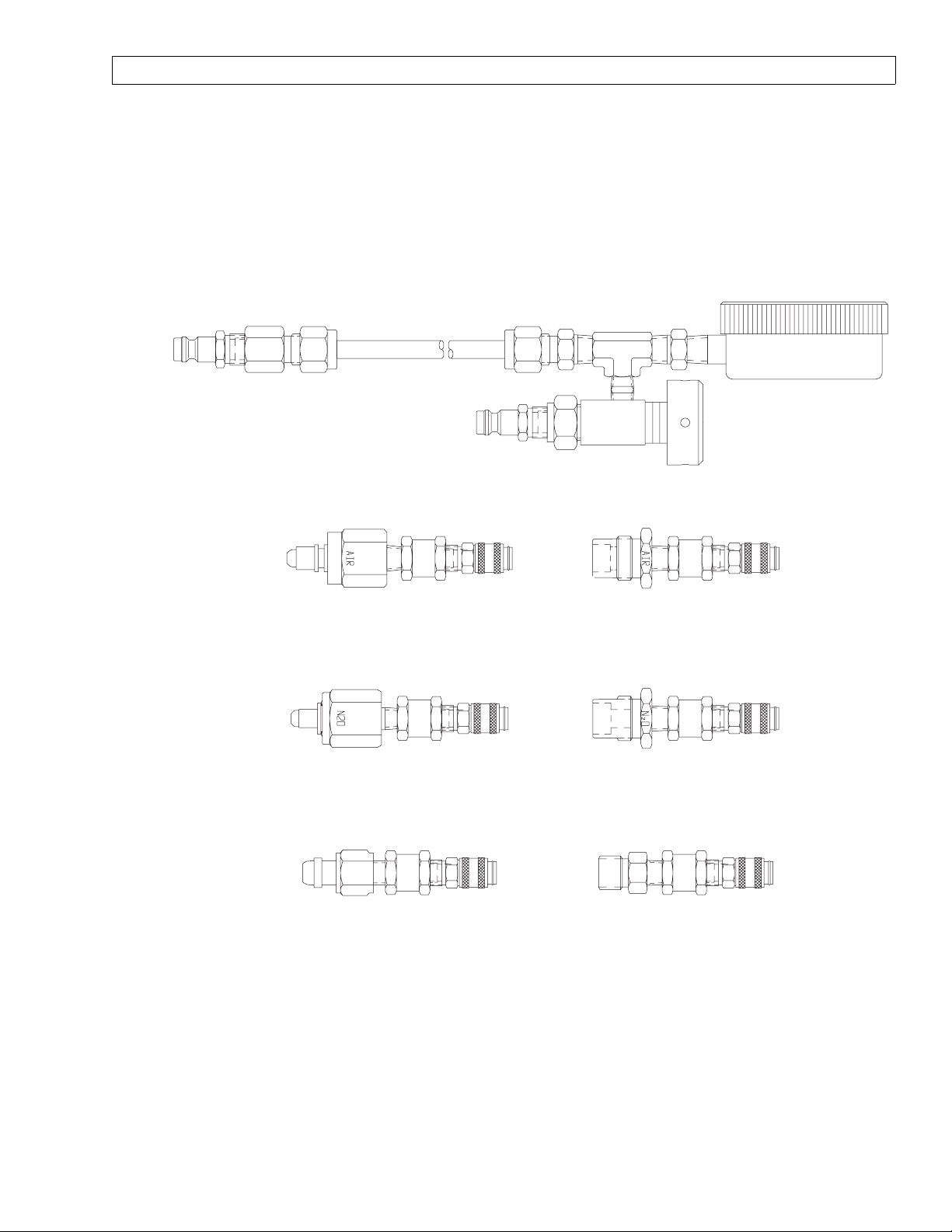
4114807 PRESSURE TEST ASSEMBLY , WITH ADAPTERS
4114830-002 4114830-001
4114830-004 4114830-003
4114830-006 4114830-005
SP15001
6-3
Page 6
RETURN TO SERVICE PROCEDURE TABLE OF CONTENTS
RETURN TO CD-ROM TABLE OF CONTENTS
NM2B PMC PROCEDURE (continued)
15
900
Liter
100
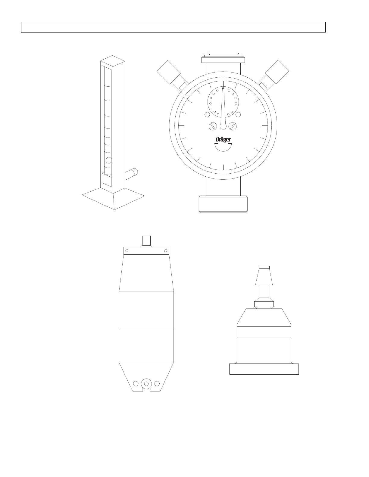
S000081
FLOW METER
TEST STAND
800
700
vol/min
600
10
500
5
200
ml
300
400
4104389
TEST TERMINAL
ADAPTER
2212300
MINUTE
VOLUMETER
8401892
SIEMENS TEST LUNG
TEST TERMINAL
SP15002
6-4
Page 7
NM2B
RETURN TO SERVICE PROCEDURE TABLE OF CONTENTS
RETURN TO CD-ROM TABLE OF CONTENTS
PMC PROCEDURE (continued)
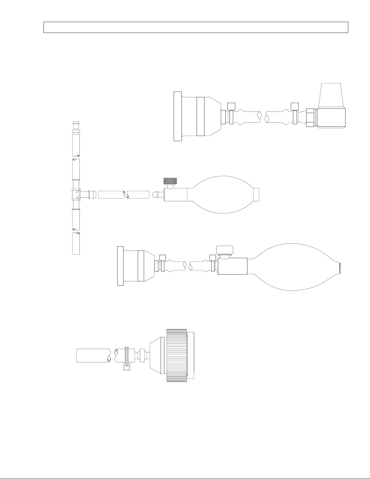
TEST TERMINAL
S010158
FRESH GAS OUTLET VOLUME TEST DEVICE
4115041
FRESH GAS
LEAK TEST DEVICE
TEST TERMINAL
S010159
BREATHING SYSTEM LEAK TEST DEVICE
4115042
VOLUMETER/
FRESH GAS HOSE
ADAPTER
SP15003
6-5
Page 8
RETURN TO SERVICE PROCEDURE TABLE OF CONTENTS
RETURN TO CD-ROM TABLE OF CONTENTS
NM2B PMC PROCEDURE (continued)
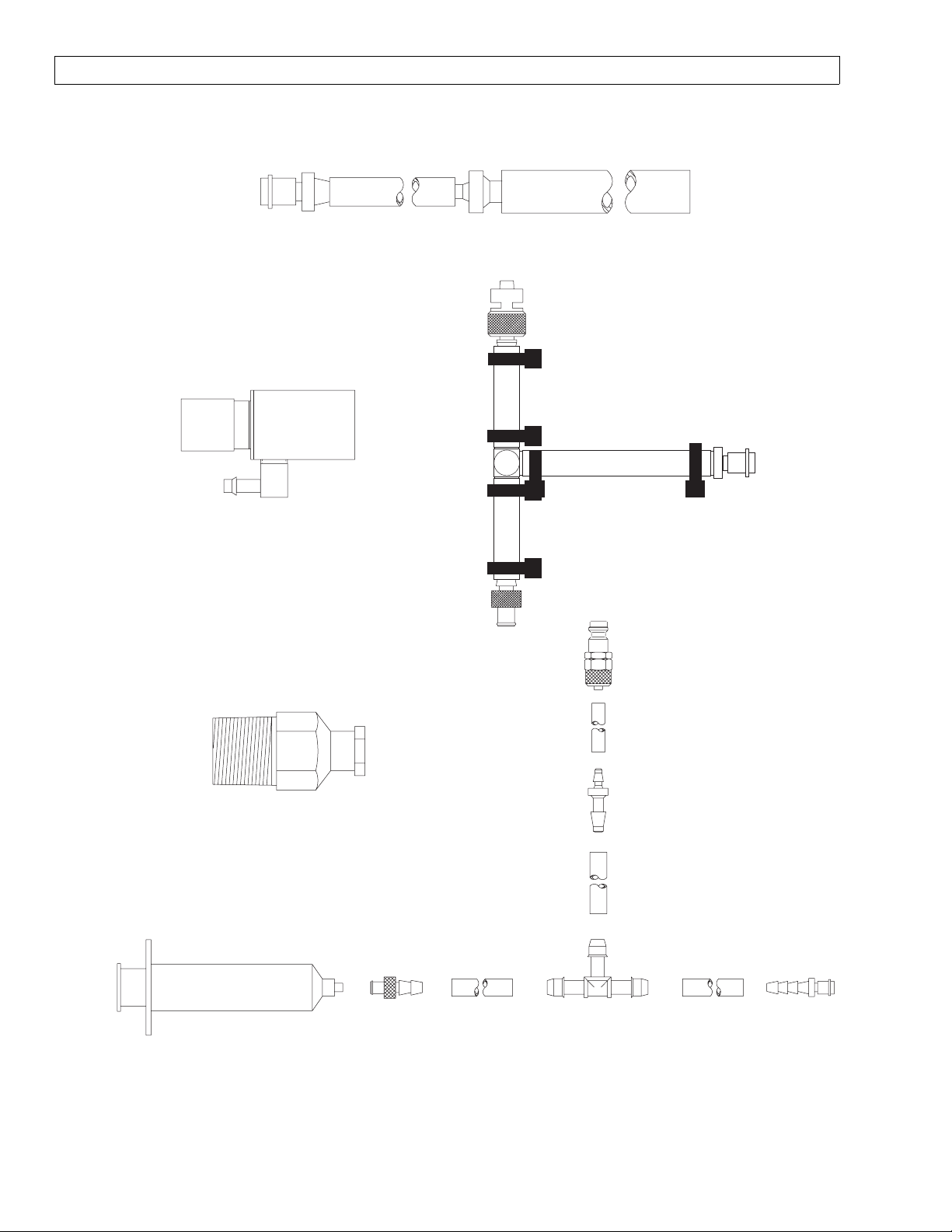
4115038
PDM TO PATIENT SUCTION ADAPTER
AVENGER
4108114
SCAVENGER ADAPTER
4110709
LUER (F) 1/8 MPT
ADAPTER FOR TOP PORT
ON CAPNOMED FLOW METER
4116111-001
NIBP W/LUER
TEST ADAPTER
4115043
PDM TO
MONITOR ADAPTER
6-6
SP15004
Page 9

NM2B
RETURN TO SERVICE PROCEDURE TABLE OF CONTENTS
RETURN TO CD-ROM TABLE OF CONTENTS
PMC PROCEDURE (continued)
Periodic Manufacturer's Certification General Instructions
The purpose of this manual is to provide detailed instructions for performing a Periodic
Manufacturer’s Certification (PMC) inspection on a Narkomed 2B Anesthesia machine.
A PMC consists of a complete Periodic Manufacturer’s Service procedure and a certification level
inspection based on Draeger Medical, Inc. Recommendations and equipment performance.
Additional inspections are also performed to insure proper product labeling.
Several additional documents have been created to ensure the success of this new program.
Following is a brief description of the purpose of each document.
Field Service Procedure:
Periodic Manufacturer’s Certification Forms - Part Number SP00175. This procedure illustrates
sample checklists with typical periodic maintenance items filled in, including vapor concentrations
verification tests, parts replaced, general comments and certification levels. Also included are
sample PMC labels marked to show several levels of certifications. An excerpt from DMI’s
Anesthesia System Risk Analysis and Risk Reduction is included, and also a sample of an
Executive Summary to be furnished to the hospital’s Risk Manager or Chief of Anesthesia.
Field Service Procedure:
DMI Recommendations Guidelines Index Anesthesia Systems - Part Number S010250. This
Guideline was created to provide an assessment of each machine’s certification. It contains various
comprehensive overviews of possible equipment conditions and their associated certification levels.
The first list in the Recommendation Guidelines is a reference chart for machine certification based
on equipment status. The second is an abbreviated summary of all DMI Recommendations and
Failure Codes including the Condition Number, Equipment Condition, Recommended Corrections,
Certification Code, and Tests Affected when applicable.
There is also a matrix classified as “Failure Codes” which identifies the correct manner in which to
document equipment tests that fail, or were unable to be performed due to circumstances beyond
the control of the service technician performing the inspection. (Ex: Air cylinder supply is
unavailable to perform Air High Pressure Leak test.) The Failure Codes section also indicates
suggested resolution of the situation. Failure Code numbers begin at 34 and use the same
certification levels strategy, and carry the same weight as DMI Recommendation equipment
condition codes.
The final matrix is the most comprehensive index sorted by machine model and includes Equipment
Condition, Certification Code, and DMI Recommendations. It also specifies any suggested upgrade
path including ordering information that should be taken such as installing a Bellows with
Pressure Limit Control 4109664-S01 Kit, after market modification kit to a machine not equipped
with pressure limit control.
The letters A, B, C, D and the Roman Numerals I, II are used as codes in the individual matrix for
each model of anesthesia machine. The letters A, B, C, and D are used in descending order to
indicate the certification level of the equipment. They are as follows:
A = Certified
B = Certified with Recommendations
C = Conditionally Certified
D = No Certification
6-7
Page 10

RETURN TO SERVICE PROCEDURE TABLE OF CONTENTS
RETURN TO CD-ROM TABLE OF CONTENTS
NM2B PMC PROCEDURE (continued)
Roman Numerals I and II do not affect the certification level but rather are provided to give
further instructions to the end user as follows:
I = The system in its present configuration shall only be used with a CO2 monitor incorporating
an apnea warning. The operator of the system is advised to frequently scan the CO2 readings and
alarm thresholds.
II =The present configuration of equipment requires that the unit operate at all times with an
oxygen analyzer that includes a low oxygen warning. The operator of the system is advised to
frequently scan the oxygen readings and alarm limits.
Following is an explanation of machine certification levels:
Certified- No DMI Recommendations or Failure Codes apply to machine being inspected. (Only
item number 33 - “No Recommendations” shall apply for this certification level.)
Certified with Recommendations- A numbered DMI Recommendation or Failure Code with a
code of B applies to the machine being examined.
Conditionally Certified- A numbered DMI Recommendation or Failure Code with a code of BCI
or BCII applies to the machine being examined.
No Certification- A numbered DMI Recommendation or Failure Code with a code of D applies to
the machine being examined.
When multiple recommendations apply, “No Certification” would take precedence over
“Conditionally Certified” and “Certified with Recommendations”. “Conditionally Certified” would
take precedence over “Certified with Recommendations”.
For example:
A Narkomed 2B could have DMI Recommendation number 21 and Failure Code 61.1 that apply.
21 - No ventilator pressure limit control. Code is B. 61.1 - Enflurane agent is unavailable to test.
Code is BC. Correct certification for this machine is BC, which means CONDITIONALLY
CERTIFIED WITH RECOMMENDATIONS.
A Narkomed 4 could have DMI Recommendation numbers 14 and 21 apply.
14 - CO2/Agent monitor exhaust port is not properly connected to the waste gas scavenger. Code
B. 21 - No ventilator pressure limit control. Code B.
The correct certification for this machine is B, which means “CERTIFIED WITH
RECOMMENDATIONS”.
A Narkomed 2B, 2C or GS could have DMI Recommendation 30 apply. 30 - Anesthesia machine
is equipped with inhalation anesthesia vaporizers without an agent analyzer in the breathing
system. Code B.
The correct certification for this machine is B, which means “CERTIFIED WITH
RECOMMENDATIONS”.
A Narkomed 6000 could have no DMI Recommendations or Failure Codes apply. The correct
certification level for this machine is Code A, “CERTIFIED”. The correct certification for this
machine is A, which means “CERTIFIED”.
Code, D also means “NO CERTIFICATION”, also means the machine shall not receive a
Periodic Manufacturer’s Certification label. The machine shall receive a “WARNING This System Is Not Certified” label, P/N 4114857. This label shall be placed at a
prominent location on the right side of the machine after all other previous PM and
“Vigilance Audit(r) Validation” labels have been removed.
6-8
Page 11

NM2B
RETURN TO SERVICE PROCEDURE TABLE OF CONTENTS
RETURN TO CD-ROM TABLE OF CONTENTS
PMC PROCEDURE
PM Certification Procedure for Narkomed 2B Anesthesia System
1. Use the PM Certification form for Narkomed 2B/ 2C/ GS Anesthesia Systems (P/N
S010211).
2. Completely fill in the header information.
3. Determine if the ventilator has an MJV-2 square Clippard valve. If ventilator has an
MJV-2, perform the lubrication procedure every 12 months in accordance with
SP00062. Place a check mark and indicate the next lubrication due date in the “Vent
Valve Lube Due” line on the Periodic Manufacturer’s Certification form. If the
ventilator has a Humphrey valve (lubrication is not required), indicate so with a (H)
next to the “Vent Valve Lube Due” line on the Periodic Manufacturer’s Certification
form.
4. Replace the VENTILATOR RELIEF VALVE DIAPHRAGM every 12 months in
accordance with SP00075. Place a check mark and indicate the next replacement
date at “Relief Valve Diaphragm Due” line on the Periodic Manufacturer’s
Certification form.
5. If machine is equipped with a HALOTHANE Dräger Vapor 19 or 19.1 vaporizer,
determine if vaporizer must be inspected for soil condition one. Check the serial
number plate located on the rear of the vaporizer for a plus (+) preceding the serial
number. A HALOTHANE vaporizer serial number not preceded with a (+) must be
tested for soil in accordance with SP00073. If vaporizer does not need to be inspected,
indicate so with a plus (+) next to the “Vapor Inspection (H)” line on the Vigilance
Audit form. If vaporizer is soil condition 0, indicate so with “SOIL 0” written next to
the “Vapor Inspection (H)” line on the Vigilance Audit form. If vaporizer is soil
condition one, indicate so with “SOIL 1” written next to the “Vapor Inspection (H)”
line on the Vigilance Audit form. Place a “CAUTION DO NOT USE” label (part #
4114327) on the vaporizer, and issue a departmental alert. The TSR shall also seek
permission from the equipment operator to remove the failed vaporizer from the
machine and apply a replacement vaporizer or an adapter block onto the mount. All
“SOIL 1” vaporizers must be removed from service for machine to receive
certification.
6. Perform the vapor concentration test on all Dräger vapor vaporizers in accordance
with SP00073 at a six month maximum interval. Perform the vaporizer concentration
test on all Desflurane vaporizers in accordance with SP00091 for fixed mount
vaporizers and SP00189 for user removable D-tec vaporizers at a six month
maximum interval. For every vaporizer tested, fill out a “VAPOR VAPORIZER
CALIBRATION CHECK” label (part # S010016). Information on this label shall
include your signature, type of agent, date tested, a No Agent To Test or the test
results @ 1%, 2.5%, 4% for H, E, I, or S vaporizers, or @ 4%, 10%, 12%, 16% for
Desflurane vaporizers, and a PASS or FAIL indication. This label shall be attached to
the upper right side of the vaporizer. If vaporizer fails the concentration verification,
internal leak, or exclusion system tests, check “NO” in the “RECOMMENDED FOR
USE” section on the PM Certification form. Place a “CAUTION DO NOT USE” label
(part # 4114327) on the vaporizer, and issue a departmental alert. The TSR shall also
seek permission from the customer to remove the failed vaporizer from the machine
and install a replacement vaporizer or an adapter block onto the mount. All
nonfunctional vaporizers must be removed from service for machine to receive
certification.
6-9
Page 12

RETURN TO SERVICE PROCEDURE TABLE OF CONTENTS
RETURN TO CD-ROM TABLE OF CONTENTS
NM2B PMC PROCEDURE (continued)
7. Proceed with PM Certification procedure. If any tests fail refer to the “Failure
Codes” listing in DMI Recommendations Guidelines Index (P/N S010250) to
determine correct certification level starting point. Failure codes shall be
documented on the “RECOMMENDATIONS / GENERAL COMMENTS” section of
the PM Certification form and on the Executive Summary. If a test fails that has
not been identified by the “Failure Codes” list, consult with Draeger Medical, Inc. to
assess the proper certification level.
8. Based on the “EQUIPMENT CONDITION” inspect the machine for any “DMI
RECOMMENDATIONS” that would apply. Use the Narkomed 2C section of the
“RECOMMENDATION GUIDELINES INDEX” (P/N S010250). Note all applicable
DMI recommendations on the Executive Summary.
NOTE: If using a carbon form, indicate the Equipment Condition number and to see
reverse side under the “RECOMMENDATIONS / GENERAL COMMENTS”
section of the form.
9. Determine the correct certification level of the machine based on the combined
lowest common denominator of “Equipment Conditions” and “Failure Codes”. If the
machine is at least conditionally certified fill out the “PM CERTIFICATION” label.
Check the box(s) on the validation label where appropriate. Write the month and
year, (three months from date of PM Certification) next to “NEXT VISIT DUE:”. If
certification level is “D”, machine shall not receive a “PM CERTIFICATION” label.
Any machine not receiving a PM Certification label shall receive a “WARNING
NOT CERTIFIED” label, P/N 4114857. This label shall be placed at a prominent
location on the left side of the machine after all other previous PMC and Vigilance
Audit Validation labels have been removed.
10. In the “CERTIFICATION LEVEL” section of the PM Certification form, record the
last visit certification level, the current certification level and the next visit due
month and year, (three months from date of PM Certification) in the spaces
provided.
11. If applicable, remove the previous PM CERTIFICATION VALIDATION label and
attach the new label (P/N S010006 w/phone #, or S010007 w/o phone #) in a
prominent location on the rear of the anesthesia machine.
12. Check the appropriate boxes on the “PM CERTIFICATION NOTICE” label, (part #
S010011). If the machine is not certified, the last box of this notice label shall be
marked. Attach this notice near the flowmeter shield of the anesthesia machine.
13. Have the customer sign each PM Certification form or the Executive Summary, and
review any Failure Codes equipment conditions and DMI Recommendations with
the customer.
14. Return top copy to Draeger Medical, Inc. Service Department, keep middle copy for
service organization records, give bottom copy to customer.
6-10
Page 13

NM2B
(9)
(9)
(9)
(9)
RETURN TO SERVICE PROCEDURE TABLE OF CONTENTS
RETURN TO CD-ROM TABLE OF CONTENTS
PMC PROCEDURE (continued)
6.1 SELF-DIAGNOSTICS
6.1.1 Turn the System Power switch to ON and verify the “ON” LED is lighted?
6.1.2 Verify all LED’s on the keypad and ventilator displays are lit if applicable.
Verify the flowmeter lights operate properly.
6.1.3 Verify that the following is displayed on the alarm CRT:
VIDEO TEST PASS NARKOMED 2B
FIRMWARE TEST PASS VERSION x.xx DIAGNOSTICS
MEMORY TEST PASS COPYRIGHT, NAD INC. 1987-94
TIMERS TEST PASS
ANALOG TEST PASS
AUDIO TEST - PRIMARY PASS
- BACKUP PASS
SERIAL I/O TEST PASS
CLOCK TEST PASS
BACKUP MEMORY TEST PASS
AC POWER TEST PASS
RESERVE POWER TEST PASS
FUNCTIONAL
6.1.4 Record the machine software version on the header of the checklist form.
6.2 ELECTRICAL SAFETY- One Year Service Interval; Due Date _____
6.2.1 Ground Continuity
6.2.1.1 Unplug the AC power cord for all devices mounted to the
machine that may provide an alternate path to earth ground,
such as a Desflurane vaporizer.
6.2.1.2 Unplug the machine’s AC power cord and plug the power cord
of the safety analyzer into this AC receptacle.
NOTE: Do not plug the safety analyzer power cord into a line
isolation monitor circuit, as inaccurate readings may
occur.
NOTE: The BIOTECH 501 PRO will automatically test the
source outlet for open ground (or ground resistance of
31 Ohms or higher), reverse polarity, open neutral and
open line. (The latter two conditions will prevent the
analyzer from powering up.)
6.2.1.3 Turn on the safety analyzer and set it’s function switch to the
GROUND WIRE RESISTANCE position. Attach the test lead
to the red SINGLE LEAD connector of the analyzer. Connect
the other end of the red test lead to the AC receptacle ground
socket on the safety analyzer. Verify a displayed resistance of
0.00 ohms or, if necessary, press the CALIBRATE key on the
front panel of the analyzer to zero the device.
6-11
Page 14

(9)
SPIROMED
T
(9)
RETURN TO SERVICE PROCEDURE TABLE OF CONTENTS
RETURN TO CD-ROM TABLE OF CONTENTS
NM2B PMC PROCEDURE (continued)
6.2.1.4 Set the safety analyzer GROUND switch to NORMAL. Set
the POLARITY switch to OFF.
6.2.1.5 Plug the machine’s AC power cord into the safety analyzer.
6.2.1.6 Apply the analyzer’s test lead to a cylinder yoke bolt.
6.2.1.7 What is the value displayed on the safety analyzer? ___ ohm
(0-0.1)
6.2.2 Circuit Isolation
6.2.2.1 Disconnect the respiratory volume sensor cord from the
interface panel.
6.2.2.2 Using a multimeter set to its highest
resistance range apply the test leads
between the yoke bolt and circuit
common at the volume interface test
pin. Refer to the corresponding
illustrations for the proper test pin
locations. There shall be no
continuity between these points.
6.2.2.3 Reconnect the respiratory volume
sensor cord to the interface panel.
6.2.3 Chassis Leakage Current
6.2.3.1 Apply the analyzer test lead to a
cylinder yoke bolt.
6.2.3.2 Set the safety analyzer to the
CHASSIS LEAKAGE CURRENT
position.
6.2.3.3 Record the total leakage current with the Polarity and
Ground switches set as follows:
Ground
Normal Normal
Open Normal
Open Reversed
Normal Reversed
Polarity
KEY
SP15005
EY
P15005A
ULTRASONIC
TEST
PIN
TES
PIN
6.2.3.4 Verify that the leakage current is 100* microamps or less in
each of the switch positions (110 microamps or less for the
220/240 volt power supply option).
6.2.3.5 300 microamps if external monitors are plugged into
convenience receptacles.
6.2.3.6 Shut off and unplug the safety analyzer. Remove the
anesthesia machine plug from the analyzer and plug it back
into the original AC receptacle.
6-12
Page 15

NM2B
(9)
(9)
RETURN TO SERVICE PROCEDURE TABLE OF CONTENTS
RETURN TO CD-ROM TABLE OF CONTENTS
PMC PROCEDURE (continued)
6.2.4 Convenience Receptacle and Auxiliary Outlet Strip
NOTE: This test will check the convenience receptacle and the auxiliary
strip outlets for fault conditions such as open ground, reverse
polarity, open line and open neutral.
6.2.4.1 Unplug all power cords from the convenience receptacles and
auxiliary outlet strip.
6.2.4.2 Plug the Receptacle Tester into the first outlet to be tested.
Verify no wiring fault is indicated then remove test plug and
move it to the next convenience outlet. Repeat this process
until all convenience outlets and auxiliary strip outlets are
tested.
6.2.4.3 Plug-in all power cords previously removed from the
convenience receptacles and auxiliary outlet strip.
6.3 CONFIGURATION
6.3.1 Press the CONFIG key.
6.3.2 Verify the correct Time and Date is displayed.
6.4 SERVICE DATA
6.4.1 From the CONFIG screen, press and hold the 21% and APNEA ALARM
DISABLE keys, then press the CONFIG key (while still holding the
previous two keys). The alarm CRT should display the Service Menu
screen.
6.4.2 Press the DIAGNOSTICS key.
6.4.3 Remedy any Error Log codes. Contact the Draeger Medical, Inc. Technical
Service Department if necessary.
6.4.4 Press the RESET DATE key.
6.4.5 Press the KEY TEST key twice.
6.4.6 The alarm CRT should display the outline of all keys on the display panel.
6.4.7 Press each key on the display panel, one at a time.
6.4.8 This step intentionally left blank.
6.4.9 As each key on the display panel is pressed, do all the corresponding keys
on the alarm CRT illuminate? ___(Y)
NOTE: The TREND key should be pressed last, because it also exits the
Key Panel Test Screen.
6.4.10 This step intentionally left blank.
6.4.11 Press the TREND key to exit the DIAGNOSTIC menu.
6.4.12 Press the exit key to exit the main service screen, If not performing
monitor calibrations press the exit key again to return to normal operation
mode.
6-13
Page 16

(9)
(9)
(9)
(9)
RETURN TO SERVICE PROCEDURE TABLE OF CONTENTS
RETURN TO CD-ROM TABLE OF CONTENTS
NM2B PMC PROCEDURE (continued)
6.5 CALIBRATIONS - One Year Service Interval; Due Date _____
6.5.1 Press the CALIBRATIONS key on the Service Menu to bring up the
Calibrations menu.
6.5.2 Remove the Oxygen sensor from the valve dome adapter, and remove the
Oxygen sensor capsule from the Oxygen sensor housing.
6.5.3 When the “OFFSET O
2 CELL A” and “OFFSET O2 CELL B” readings
(displayed in left column) Have stabilized and are as close as possible to
each other with a difference not greater than 8, press the O
2 MED key
and verify that the new offset values are stored.
NOTE: The higher the offset, the higher the calculated O
2 concentration
appears at high concentrations.
6.5.4 Put the Oxygen sensor capsule into the Oxygen sensor housing.
6.5.5 Disconnect the breathing pressure monitor’s sensor line from the
absorber.
6.5.6 Connect a pressure monitor adapter, (P/N 4115043) and calibrated
digital pressure manometer to the breathing pressure sensor line.
6.5.7 Pressurize the circuit to 60 cm H
2O and allow the Current Value to
stabilize. Reading should be between 465 and 519.
6.5.8 This step intentionally left blank.
6.5.9 This step intentionally left blank.
6.5.10 Press the BAROMED key and verify the following message:
“PRESSURE READINGS STORED”.
6.5.11 Release the pressure, disconnect the manometer and test fixture, and
reconnect the breathing pressure sensor line to the absorber.
6.5.12 Press the EXIT key to exit the Calibration Screen.
6.5.13 Press the EXIT key to Set the cursor to EXIT and press the trigger to
return to normal operation.
6.6 ABSORBER MAINTENANCE
6.6.1 Remove the O
2 sensor or the plug from the inspiratory valve dome
adapter and examine the O-rings on each assembly. Replace O-rings as
necessary.
6.6.2 Remove the inspiratory and the expiratory valve domes.
6.6.3 Are all pins on the valve crater undamaged? Inspiratory ___ (Y)
Expiratory ___ (Y)
6.6.4 Are all pins on the valve domes undamaged? Inspiratory ___ (Y)
Expiratory ___ (Y)
6.6.5 Is the valve disc in good condition? Inspiratory ___ (Y) Expiratory ___ (Y)
6.6.6 Are the valve dome washers in good condition? ___ (Y)
6-14
Page 17

NM2B
RETURN TO SERVICE PROCEDURE TABLE OF CONTENTS
RETURN TO CD-ROM TABLE OF CONTENTS
PMC PROCEDURE (continued)
6.6.7 Reinstall the inspiratory and expiratory valve domes.
6.6.8 Ultrasonic Flow Sensor - If applicable
6.6.8.1 Remove the Ultrasonic Flow Sensor connector hose.
6.6.8.2 Is the connector hose, connector, and O-ring in good condition?
___ (Y)
6.6.8.3 Remove the expiratory valve.
6.6.8.4 Is the washer under the valve in good condition? ___ (Y)
6.6.8.5 Reattach the expiratory valve.
6.6.8.6 Remove the ultrasonic flow sensor from the mounting bracket.
6.6.8.7 Remove the flow housing/transducer assembly from the
electronics housing.
6.6.8.8 Remove both transducers from the flow housing; examine
each O-ring and condition of all components, then reassemble
the ultrasonic flow sensor.
6.6.8.9 Reattach the ultrasonic flow sensor to the mounting bracket.
6.6.8.10 Reattach the connector hose between the sensor and
expiratory valve.
6.6.9. Lubrication, Spiromed Sensor - If applicable
6.6.9.1 Remove the expiratory valve.
6.6.9.2 Is the washer under the valve in good condition? ___ (Y)
6.6.9.3 Remove the Spiromed sensor.
6.6.9.4 Is the washer under the sensor in good condition? ___ (Y)
6.6.9.5 Locate the four lateral holes at the sides of the Spiromed
sensor marked by arrows.
CAUTION: Use only Sensor Lubrication Kit P/N 2218180 for the
following procedure.
6.6.9.6 Dip the tip of the pipette into the lubricant and draw lubricant
into the pipette by pulling the pin backwards.
6.6.9.7 Insert the pipette into one of the four holes as far as it will go.
Push the pin forward to its stop and inject lubricant into the
hole.
6.6.9.8 Repeat the previous 2 steps for the lubricating three
remaining holes.
6.6.9.9 Wipe any lubricant residue from the exterior of the sensor.
6.6.9.10 Reattach the sensor to the absorber top dome.
6.6.9.11 Reattach the expiratory valve to spiromed sensor.
6.6.10. Remove the inspiratory valve assembly.
6-15
Page 18

(9)
RETURN TO SERVICE PROCEDURE TABLE OF CONTENTS
RETURN TO CD-ROM TABLE OF CONTENTS
NM2B PMC PROCEDURE (continued)
6.6.11. Is the washer under the valve in good condition? ___ (Y)
6.6.12 Reinstall the inspiratory valve.
6.6.13 Are there two (2) spring clips on the absorber rods? ___ (Y)
6.6.14 Inspect the following: canisters, canister gaskets, dust cup and O-ring,
and soda lime.
6.6.15 Are the canisters, canister gaskets, dust cup and O-ring, and soda lime
in good condition? ___ (Y)
6.6.16 Verify the cm H
2O gauge at zero (0) and readjust if necessary.
NOTE: The small slotted screw is the zero adjust.
6.6.17 Reinstall the O
2 sensor plug into the inspiratory valve dome adapter.
6.6.18 Remove the 15-mm connector from the FRESHGAS OUTLET.
6.6.19 Is the Freshgas Outlet assembly in good condition? ___ (Y)
6.6.20 Reconnect the 15-mm connector to the FRESHGAS OUTLET.
6.6.21 Repack MAN/AUTO Selector Valve, If applicable
6.6.21.1 Remove the four screws securing the stick shift block to the
selector valve body and remove the block.
6.6.21.2 Remove the spring and valve channel from the valve body.
6.6.21.3 Remove all residual lubricant from the valve channel.
6.6.21.4 Remove all residual lubricant from the valve body.
6.6.21.5 Apply a minimal amount of “stop cock” lubricant (Dow
Corning High Vacuum Grease, P/N S4105908) to the tapered
surface of the valve channel, and ensure complete coverage
of lubricant.
6.6.21.6 Insert the valve channel into the valve body.
6.6.21.7 Insert the spring into the stick shift block.
6.6.21.8 Align the index pins on the stick shift block to the holes in
the valve channel.
6.6.21.9 Secure the stick shift block to the selector valve body with
the four screws that were previously removed.
6.6.21.10 Operate the selector valve handle and verify smooth
movement.
6.7 HIGH PRESSURE LEAK
NOTE: Minimum cylinder pressures required for High Pressure Leak tests are:
O
2, Air, O2-HE, N2, HE: 1000 psi \ N2O, CO2: 600 psi;
6.7.1 Turn the machine main switch to Standby.
6.7.2 Verify the Auxiliary Oxygen flow control valve is closed.
6-16
Page 19

NM2B
(9)
(9)
RETURN TO SERVICE PROCEDURE TABLE OF CONTENTS
RETURN TO CD-ROM TABLE OF CONTENTS
PMC PROCEDURE (continued)
6.7.3 Disconnect all pipeline supply hoses at the wall outlets.
6.7.4 Open then close and remove each cylinder and if applicable remove the
yoke plug from each additional yoke assembly.
6.7.5 Note the reading on each the cylinder pressure gauge and start a stop
watch.
6.7.6 Are the two (2) yoke index pins installed securely in each yoke? ___(Y)
6.7.7 Is the proper gas I.D. label affixed to each yoke? ___ (Y)
6.7.8 After two (2) minutes, is the pressure loss for each gas equal or less than
50 psi? ___(Y)
6.7.9 Verify the presence of only one (1) cylinder washer, then reattach and
secure the cylinders to each yoke assembly, then open each cylinder valve.
6.8 BREATHING SYSTEM
6.8.1 Breathing System Leak/Exclusion
6.8.1.1 Close all flow control valves.
6.8.1.2 Set the AUTO/MAN selector to BAG.
6.8.1.3 Close the APL valve.
6.8.1.4 Interconnect a 22 mm hose (P/N 9995132) between the
inspiratory valve and expiratory valve or expiratory port on
the ultrasonic flow sensor, if applicable.
6.8.1.5 Attach a test terminal (P/N 4104389) to the Fresh Gas Leak
Test Adapter (P/N 4115041) then attach the test terminal to
the bag mount.
6.8.1.6 Apply 50 cm H
2O test pressure to the absorber system and
start a stop watch.
6.8.1.7 Is the pressure on the absorber pressure gauge within 47 to 53
cm H
2O? ___(Y)
6.8.1.8 After thirty (30) seconds, is the breathing system test
pressure equal or greater than 40 cm H
2O? ___ (Y)
6.8.1.9 If applicable, turn on the left mounted vaporizer to the first
graduated marking. Reapply 50 cm H
2O of pressure to the
system and start a stopwatch. Is it possible to turn on either
the center or right vapors? ___ (N)
6.8.1.10 After thirty (30) seconds, is the left vaporizer test pressure
equal or greater than 40 cm H
2O? ___(Y) Turn off the left
vaporizer.
6.8.1.11 If applicable, turn on the center mounted vaporizer to the first
graduated marking. Reapply 50 cm H
2O of pressure to the
system and start a stopwatch. Is it possible to turn on either
the left or right vapors? ___ (N)
6-17
Page 20

(9)
(9)
(9)
(9)
(9)
RETURN TO SERVICE PROCEDURE TABLE OF CONTENTS
RETURN TO CD-ROM TABLE OF CONTENTS
NM2B PMC PROCEDURE (continued)
6.8.1.12 After thirty (30) seconds, is the center vaporizer test
pressure equal or greater than 40 cm H
2O? ___(Y) Turn off
the center mounted vaporizer.
6.8.1.13 If applicable, turn on the right mounted vaporizer to the
first graduated marking. Reapply 50 cm H
2O of pressure to
the system and start a stopwatch. Is it possible to turn on
either the left or center vapors? ___ (N)
6.8.1.14 After thirty (30) seconds, is the right vaporizer test pressure
equal or greater than 40 cm H
2O? ___ (Y) Turn off the right
mounted vaporizer.
6.8.1.15 Did all vaporizer exclusion verifications test positive?
___ (Y)
6.8.2 APL Valve
6.8.2.1 Open the APL valve to its stop.
6.8.2.2 Turn the System Power switch to ON.
6.8.2.3 Set the Oxygen flow to 8 l/min.
6.8.2.4 Is the pressure within 0 to 3 cm H
6.8.3 O
2 Flush
6.8.3.1 Attach a 33 mm x 22 Female Adapter (P/N 4115087) to the
top port of the test volumeter.
6.8.3.2 Disconnect the hose from the expiratory valve or expiratory
hose terminal on the ultrasonic flow sensor, if applicable and
attach it to the test volumeter adapter.
6.8.3.3 Close the APL valve.
6.8.3.4 Press and hold the O
the value obtained by 10.
6.8.3.5 Is the calculated O
6.8.3.6 After releasing the flush, does the flow of Oxygen stop
immediately? __ (Y)
6.8.3.7 Remove the test equipment.
6.8.4 Expiratory Valve Leak
6.8.4.1 Connect a 22 mm hose (P/N 9995132) between the
inspiration valve and the bag mount.
2O? ___ (Y)
2 FLUSH button for 6 seconds; multiply
2 flush flow rate 45 to 65 l/min.? ___ (Y)
6.8.4.2 Connect a test terminal (P/N 4104389) to the expiration
valve or expiratory hose terminal on the ultrasonic flow
sensor, if applicable.
6.8.4.3 Connect a 0-250 ml/min. flowmeter (S000081) to the test
terminal.
6-18
Page 21

NM2B
(9)
(9)
RETURN TO SERVICE PROCEDURE TABLE OF CONTENTS
6.8.4.4 Turn up the Oxygen flow until the system pressurizes to 30
2O. Adjust the APL valve as necessary to maintain 30 cm
cm H
H
2O.
6.8.4.5 Is the value indicated on the flowmeter within 0 to 60 ml/
min.? ___ (Y)
6.8.4.6 Close APL valve.
6.8.4.7 Remove all test equipment.
6.8.5 Inspiration Valve Leak
6.8.5.1 Turn the System Power switch to Standby.
6.8.5.2 Connect a test terminal (P/N 4104389) to the inspiratory
valve.
6.8.5.3 Connect a Fresh Gas Leak Adapter (P/N 4115041) and
calibrated pressure meter to the test terminal on the
inspiratory valve.
6.8.5.4 Connect another test terminal to the bag connector.
RETURN TO CD-ROM TABLE OF CONTENTS
PMC PROCEDURE (continued)
6.8.5.5 Connect a 0-250 ml/min. flowmeter (S000081) to the test
terminal on the bag mount.
6.8.5.6 Pressurize the test circuit to 30 cm H
6.8.5.7 Is the value indicated on the flowmeter within 0 to 60 ml/
min.? ___ (Y)
6.8.5.8 Turn the system power switch to ON.
6.8.5.9 Remove all test equipment.
6.8.6 PEEP Valve w/Bypass - If applicable
6.8.6.1 Open the APL valve. If PEEP valve is mounted on the bellows,
set the AUTO/BAG valve to AUTO.
6.8.6.2 Interconnect the inspiratory valve and expiratory valve or
expiratory port on the ultrasonic flow sensor, if applicable
with a 22 mm hose (P/N 9995132).
6.8.6.3 Attach a Breathing System Leak Test Adapter (P/N S010159)
to the bag mount.
6.8.6.4 Disconnect the pressure pilot line from the absorber and
replace it with a PDM To Monitor Adapter (P/N 4115041).
6.8.6.5 Connect a test gauge to the adapter.
2O.
6.8.6.6 Set the O
2 flow to 5 l/min.
6.8.6.7 * Place the PEEP bypass in the ON position.
6.8.6.8 Adjust the absorber PEEP valve clockwise to the maximum
position.
6.8.6.9 Does the PEEP valve adjust smoothly? ___ (Y)
6-19
Page 22

(9)
(9)
RETURN TO SERVICE PROCEDURE TABLE OF CONTENTS
RETURN TO CD-ROM TABLE OF CONTENTS
NM2B PMC PROCEDURE (continued)
6.8.6.10 Is the maximum PEEP indicated on the test gauge within 15
to 22 cm H
2O? ___ (Y)
6.8.6.11 * Place the PEEP bypass in the OFF position.
6.8.6.12 * Does the PEEP return to <
6.8.6.13 Adjust the absorber PEEP valve counterclockwise to its
minimum position.
6.8.6.14 Does the PEEP return to <
6.8.6.15 Close the O
2 flow control valve.
6.8.6.16 Remove the test equipment and reconnect the pilot line to
the absorber.
6.8.6.17 If PEEP valve is mounted on the bellows return the AUTO/
BAG valve to BAG.
* These items apply only to machines with a PEEP by-pass.
6.8.7 Bain Circuit Adapter - If applicable
6.8.7.1 Close the Bain Circuit APL valve by turning the knob fully
clockwise.
6.8.7.2 Verify the cm H
2O gauge at zero (0) and readjust if
necessary.
NOTE: The small slotted screw is the zero adjust.
6.8.7.3 Insert the O
2 sensor plug into the O2 sensor inlet on the
Bain Circuit.
3 cm H2O? ___(Y)
3 cm H2O? ___(Y)
6.8.7.4 Attach a Breathing System Leak Device (P/N S010159) to
the Breathing Bag port on the Bain Circuit.
6.8.7.5 Disconnect the pressure pilot line from the Bain Circuit and
replace it with a PDM To Monitor Adapter (P/N 4115041).
6.8.7.6 Connect a test gauge to the adapter.
6.8.7.7 Occlude the expiration port on the Bain Circuit.
6.8.7.8 Apply 50cm H
6.8.7.9 Is the pressure indicated on the cm H
H
2O of the digital pressure meter reading? ___ (Y)
6.8.7.10 After 30 seconds, is the test pressure 45 to 50 cm H
2O test pressure to the Bain Circuit.
2O gauge within 3 cm
2O?
___ (Y)
6.8.7.11 Open the APL valve by turning the knob fully counterclockwise.
6.8.7.12 Connect a Fresh Gas Outlet Volume Adapter (P/N S010158)
between the fresh gas outlet and the Expiration port of the
Bain Circuit.
6.8.7.13 Set the O
2 flow to 8 l/min.
6-20
Page 23

NM2B
(9)
(9)
(9)
(9)
(9)
RETURN TO SERVICE PROCEDURE TABLE OF CONTENTS
RETURN TO CD-ROM TABLE OF CONTENTS
PMC PROCEDURE (continued)
6.8.7.14 Is the test pressure within 0 to 3 cm H2O? ___ (Y)
6.8.7.15 Remove the test equipment and reconnect the pilot line to the
Bain Circuit.
6.9 OXYGEN ANALYZER
6.9.1 Press the O
2 CAL key to perform an 02 Calibration.
NOTE: Make sure that the sensor has stabilized in ambient air for several
minutes.
6.9.2 After calibration is completed, is the O
2 concentration 21 %? ___(Y)
6.9.3 The warning message % OXYGEN LOW shall appear on the central alarm
display, and a continuous alarm shall sound.
6.9.4 Press the Alarm Silence key and verify the audio alarm is silenced.
6.9.5 Place the Oxygen sensor into the inspiratory valve dome adapter.
6.9.6 Set the AUTO/MAN selector to BAG.
6.9.7 Close the APL valve.
6.9.8 Attach a 22 mm hose (P/N 9995132) to the inspiratory valve.
6.9.9 Attach a Breathing System Leak Test Device (P/N S010159) to the bag
mount.
6.9.10 Press the O
6.9.11 After 10 seconds, is the O
6.9.12 Release the O
2 Flush.
2 concentration 90 to 100 % O2? ___ (Y)
2 Flush, does the flow cease immediately? ___ (Y)
6.9.13 Set the Oxygen flow to 10 l/min.
6.9.14 After 1 minute, is the O
2 concentration 97 to 100%? ___ (Y)
6.10 FLOWMETERS/GAS CONCENTRATIONS
6.10.1 Oxygen Flowmeter
6.10.1.1 Is it possible to adjust the flow of Oxygen over the full range of
the flowmeters? ___ (Y)
6.10.1.2 Set the Oxygen flow to 4 l/min.
6.10.1.3 Is the correct flow control knob and label attached to the
Oxygen flow control valve? ___ (Y)
6.10.2 Oxygen-Helium Flowmeter - If applicable
6.10.2.1 Set the gas selector to ALL GAS, if applicable. Is it possible to
adjust the flow of the Oxygen-Helium over the full range of
the flowmeter? ___ (Y)
6.10.2.2 Set the Oxygen-Helium flow to 2 l/min.
6.10.2.3 *After the value stabilizes, is the O
2? ___ (Y)
O
6-21
2 concentration 72 to 78%
Page 24

(9)
(9)
(9)
RETURN TO SERVICE PROCEDURE TABLE OF CONTENTS
RETURN TO CD-ROM TABLE OF CONTENTS
NM2B PMC PROCEDURE (continued)
6.10.2.4 Close the Oxygen-Helium flow valve.
6.10.2.5 Is the correct flow control knob and label attached to the
Oxygen-Helium flow control valve? ___ (Y)
*Oxygen-Helium specifications are given @ 25% O
deviations will affect this value. The expected concentration values can
be obtained by replacing the ‘25’ % O
actual cylinder content as follows:
(2 l/min O
2-HE x ‘25’) + (4 l/min. O2 x 100 )
6 l/min - Total Flow =% O2
6.10.3 Helium Flowmeter - If applicable
6.10.3.1 Set the gas selector to ALL GAS, if applicable.
6.10.3.2 Is it possible to adjust the flow of the Helium over the full
range of the flowmeter? ___ (Y)
6.10.3.3 Set the Helium flow to 2 l/min.
6.10.3.4 After the value stabilizes, is the O
___ (Y)
6.10.3.5 Close the Helium flow valve.
6.10.3.6 Is the correct flow control knob and label attached to the
Helium flow control valve? ___(Y)
6.10.4 Nitrogen Flowmeter - If applicable
6.10.4.1 Set the gas selector to ALL GAS, if applicable.
2. Cylinder content
2 value given for O2-HE with the
2 concentration 64 to 70?
6.10.4.2 Is it possible to adjust the flow of the Nitrogen over the full
range of the flowmeter? ___ (Y)
6.10.4.3 Set the Nitrogen flow to 2 l/min.
6.10.4.4 After the value stabilizes, is the O
___ (Y)
6.10.4.5 Close the Nitrogen flow valve.
6.10.4.6 Is the correct flow control knob and label attached to the
Nitrogen flow control valve? ___(Y)
6.10.5 Carbon Dioxide Flowmeter - If applicable
6.10.5.1 Set the gas selector to ALL GAS, if applicable. Is it possible
to adjust the flow of the Carbon Dioxide over its range of 550
ml/min.? ___ (Y)
6.10.5.2 Set the Oxygen flow to 1000 ml/min.
6.10.5.3 Set the Carbon Dioxide flow to 500 ml/min.
6.10.5.4 After the value stabilizes, is the O
___ (Y)
6.10.5.5 Close the Carbon Dioxide flow valve.
2 concentration 64 to 70%?
2 concentration 64 to 70%?
6-22
Page 25

NM2B
(9)
(9)
(9)
(9)
RETURN TO SERVICE PROCEDURE TABLE OF CONTENTS
RETURN TO CD-ROM TABLE OF CONTENTS
PMC PROCEDURE (continued)
6.10.5.6 Readjust the Oxygen flow to 4 l/min.
6.10.5.7 Is the correct flow control knob and label attached to the
Carbon Dioxide flow control valve? ___ (Y)
6.10.6 Air Flowmeter - If applicable
6.10.6.1 If not configured with an Air Cylinder yoke, attach the Air
Pipeline hose.
6.10.6.2 Set the gas selector to ALL GAS, if applicable. Is it possible to
adjust the flow of the Air over the full range of the flowmeter?
___ (Y)
6.10.6.3 Set the Air flow to 2 l/min.
6.10.6.4 After the value stabilizes, is the O
___ (Y)
6.10.6.5 Close the Air flow control valve.
6.10.6.6 Is the correct flow control knob and label attached to the Air
flow control valve? ___ (Y)
6.10.7 Nitrous Oxide Flowmeter
6.10.7.1 Set the Nitrous Oxide flow to 2 l/min.
6.10.7.2 After the value stabilizes, is the O
___ (Y)
6.10.7.3 Is the correct flow control knob and label attached to the
Nitrous Oxide flow control valve? ___ (Y)
6.10.7.4 Is it possible to adjust the flow of Nitrous Oxide over the full
range of the flowmeter? ___ (Y)
6.10.8 Oxygen Ratio Control - If applicable
6.10.8.1 Open the Nitrous Oxide flow control valve to the stop position.
6.10.8.2 After the value stabilizes, is the O
___(Y)
6.10.8.3 Set the Oxygen flow to 2 l/min.
2 concentration 71 to 77%?
2 concentration 64 to 70%
2 concentration 21 to 29%?
6.10.8.4 After the value stabilizes, is the O
2 concentration 21 to 29%?
___ (Y)
6.10.8.5 Set the Oxygen flow to 1 l/min.
6.10.8.6 After the value stabilizes, is the O
2 concentration 21 to 29%?
___ (Y)
6.10.8.7 Reduce the O
2 flow to 500 ml/min. Verify that the N2O flow is
greater than or equal to 600 ml/min.
6.10.8.8 Close the Oxygen flow control valve.
6.10.8.9 Close the Nitrous Oxide flow control valve.
6-23
Page 26

(9)
(9)
(9)
(9)
RETURN TO SERVICE PROCEDURE TABLE OF CONTENTS
RETURN TO CD-ROM TABLE OF CONTENTS
NM2B PMC PROCEDURE (continued)
6.10.9 Oxygen Ratio Monitor Controller - If applicable
6.10.9.1 Close the Oxygen flow control valve.
6.10.9.2 * Set the Gas Selector switch to “O
2+N2O”.
6.10.9.3 Slowly increase the Oxygen flow until Nitrous Oxide begins
to flow. Is the oxygen flow rate 200 to 400 ml/min.? ___ (Y)
6.10.9.4 Slowly increase the Oxygen flow until the “O
2/N2O FLOW
RATIO” LED on the alarm panel is lighted. Is the nitrous
oxide flow rate 150-300 ml/min, or 700-800 if configured
with Minimum O
2 Flow Elimination? ___ (Y)
6.10.9.5 Set the oxygen flow to 1000 ml/min.
6.10.9.6 Open the nitrous oxide flow control valve to the stop
position.
6.10.9.7 Is the “O
2/N2O FLOW RATIO” alarm activated? ___ (Y)
6.10.9.8 After the value stabilizes, is the oxygen concentration 21 to
29%? ___(Y)
6.10.9.9 Adjust the oxygen flow to 2 l/min.
6.10.9.10 After the value stabilizes, is the oxygen concentration 21 to
29%? ___(Y)
6.10.9.11 Adjust the oxygen flow to 4 l/min.
6.10.9.12 After the value stabilizes, is the oxygen concentration 21 to
29%? ___ (Y)
6.10.9.13 Is the “O
2/N2O FLOW RATIO” alarm activated? ___ (Y)
6.10.9.14 * Set the Gas Selector switch to ALL GASES.
6.10.9.15 * Is the “O
2/N2O FLOW RATIO” alarm activated? ___ (N)
6.10.9.16 * Set the Gas Selector switch to “O
6.10.9.17 Close the oxygen flow control valve.
6.10.9.18 What is the flow of nitrous oxide? ___ ml/min. (0)
6.10.9.19 Is the “O
2/N2O FLOW RATIO” alarm activated? ___ (N)
6.10.9.20 Close the nitrous oxide flow control valve.
* Does not apply to 2-gas machines.
6.10.10 Auxiliary Oxygen Flowmeter - If applicable
6.10.10.1 Connect a test pressure monitor to the outlet using a PDM/
Suction adapter (P/N 4115038).
6.10.10.2 Increase the pressure to 50 cm H
6.10.10.3 After 10 seconds, is the pressure within 40 to 60 cm H
___ (Y)
6.10.10.4 Remove the test gauge and adapter.
2+N2O”.
2O.
2O?
6-24
Page 27

NM2B
(9)
(9)
RETURN TO SERVICE PROCEDURE TABLE OF CONTENTS
RETURN TO CD-ROM TABLE OF CONTENTS
PMC PROCEDURE (continued)
6.10.10.5 Is it possible to adjust the flow over the full range of the
flowmeter? ___(Y)
6.10.10.6 Set the flow rate to 5 l/min.
6.10.10.7 Hold the Oxygen sensor at the flowmeter outlet.
6.10.10.8 After the value stabilizes, is the O
2 concentration within 80 to
100% ___ (Y)
6.10.10.9 Replace the Oxygen sensor into the Inspiratory valve dome.
6.10.10.10 Close the Auxiliary Oxygen flow control valve.
6.11 HIGH PRESSURE REGULATOR - Six Month Service Interval; Due Date _____
6.11.1 N
NOTE: Minimum cylinder pressure for N
2O Regulator
2O regulator test is 600 psi.
6.11.1.1 Configure the test gauge (P/N 4114807) using a N
DISS connector (P/N 4114830-004) on the hose, and N
body connector (P/N 4114830-003) on the valve body side. If
the machine is configured with CSA style fittings reverse the
position of the connectors.
6.11.1.2 Connect the test fixture hose to the machine’s Nitrous Oxide
pipeline inlet.
6.11.1.3 Connect the Nitrous Oxide pipeline supply hose to the test
fixture.
6.11.1.4 Open the Nitrous Oxide and the Oxygen cylinder valves.
2O nut/stem
2O DISS
6.11.1.5 Set the Oxygen and Nitrous Oxide flows to 4 l/min.
6.11.1.6 Depress the push button on the test device.
6.11.1.7 Release the push button. After the pressure decay stabilizes,
is the regulator output pressure 40 to 49 psi? ___(Y)
6.11.1.8 Remove the test fixture.
NOTE: If a pressure decrease does not occur, either the
hospital’s supply pressure is too low or the regulator
pressure is set too high.
6.11.2 Air Regulator - If applicable
NOTE: Minimum cylinder pressure for Air regulator test is 1000 psi.
6-25
Page 28

(9)
RETURN TO SERVICE PROCEDURE TABLE OF CONTENTS
RETURN TO CD-ROM TABLE OF CONTENTS
NM2B PMC PROCEDURE (continued)
6.11.2.1 Configure the test gauge (P/N 4114807) using an Air nut/
stem DISS connector (P/N 4114830-002) on the hose and a
DISS body connector (P/N 4114830-001) on the valve body
side. If the machine is configured with CSA style fittings
reverse the position of the connectors.
6.11.2.2 Connect the test fixture hose to the machine’s Air pipeline
inlet.
6.11.2.3 Connect the Air pipeline supply hose to the test fixture.
6.11.2.4 Set the Air flow to 4 l/min.
6.11.2.5 Depress the push button on the test device.
6.11.2.6 Release the push button. After the pressure decay stabilizes,
is the regulator output pressure within tolerance given in
the following table? ___ (Y)
NOTE: If a pressure decrease does not occur, either the
hospital’s supply pressure is too low or the regulator
pressure is set too high.
Cylinder
Pressure psi
USA Compensated
Regulator output
tolerances
2000 38 to 44 41 to 47
1800 39 to 45 42 to 48
1600 40 to 46 43 to 49
1400 41 to 47 44 to 50
1200 42 to 48 45 to 51
1000 43 to 49 46 to 52
6.11.2.7 Remove the test fixture.
6.11.3 O
2 Regulator
NOTE: Minimum cylinder pressure for O
6.11.3.1 Configure a test gauge (P/N 4114807) using an O
DISS connector (P/N 4114830-006) on the hose and an O
DISS body connector (P/N 4114830-005) on the valve body
side. If the machine is configured with CSA style fittings
reverse the position of the connectors.
ISO Compensated
Regulator output
tolerances
2 regulator test is 1000 psi.
2 nut/stem
2
6.11.3.2 Connect the test fixture hose to the machine’s Oxygen
pipeline inlet.
6.11.3.3 Connect the Oxygen pipeline supply hose to the test fixture.
6-26
Page 29

NM2B
(9)
(9)
(9)
(9)
RETURN TO SERVICE PROCEDURE TABLE OF CONTENTS
RETURN TO CD-ROM TABLE OF CONTENTS
PMC PROCEDURE (continued)
6.11.3.4 Set the Oxygen flow to 4 l/min.
6.11.3.5 Depress the push button on the test device.
6.11.3.6 Release the push button. After the pressure decay stabilizes,
is the regulator output pressure within the tolerance given in
the following table? ___ (Y)
NOTE: If a pressure decrease does not occur, either the
hospital’s supply pressure is too low or the regulator
pressure is set too high.
Cylinder
Pressure psi
USA Compensated
Regulator output
ISO Compensated
Regulator output
tolerances
2000 38 to 44 41 to 47
1800 39 to 45 42 to 48
1600 40 to 46 43 to 49
1400 41 to 47 44 to 50
1200 42 to 48 45 to 51
1000 43 to 49 46 to 52
6.12 LOW O
2 SUPPLY - Six Month Service Interval
6.12.1 Close the Oxygen cylinder valve and drain all Oxygen pressure.
6.12.2 Depress the push button on the test device.
6.12.3 Adjust the Oxygen flow to 500 ml/min.
6.12.4 Release the test device push button.
tolerances
6.12.5 Is the pressure on the test gauge when the LO O
2 SUPPLY message
appears within 34 to 40 psi? ___ (Y)
6.12.6 Remove the test equipment.
6.13 OXYGEN SUPPLY FAILURE PROTECTION
6.13.1 Connect all pipeline supplies.
6.13.2 Close the Oxygen flow control valve if applicable.
6.13.3 *Is the flow of Oxygen 100 to 200ml/min; or 0 ml/min for Minimum O
Flow Elimination? ___ (Y)
6.13.4 Open the Nitrous Oxide flow control valve.
6.13.5 *Is the flow of Nitrous Oxide 375 to 750 ml/min.; or 0 ml/min if without
Bypass? ___ (Y)
6-27
2
Page 30

(9)
(9)
(9)
(9)
(9)
(9)
(9)
RETURN TO SERVICE PROCEDURE TABLE OF CONTENTS
RETURN TO CD-ROM TABLE OF CONTENTS
NM2B PMC PROCEDURE (continued)
6.13.6 Adjust the Oxygen, Nitrous Oxide and additional gas flow to 4 l/min. Set
Carbon Dioxide Flow to 500 ml/min., if applicable.
6.13.7 Disconnect the Oxygen pipeline supply and close the Oxygen cylinder
valve.
6.13.8 Do all flows cease when the Oxygen pressure is depleted? ___(Y)
6.13.9 Reconnect the Oxygen pipeline supply.
6.13.10 Close all cylinder valves and then disconnect the Nitrous Oxide pipeline
supply, and Air pipeline if applicable.
6.13.11 Drain the cylinder contents then reconnect the pipeline supplies.
6.13.12 Close all flow control valves.
* Nitrous Oxide Bypass flow and Minimum Oxygen flow specifications are given @
50 psi. Pipeline pressure deviations may affect these tests.
6.14 PRESSURE MONITOR
6.14.1 Disconnect the breathing pressure sensor line from the absorber.
6.14.2 Connect a PDM Adapter (P/N 4115043) and test pressure gauge to the
breathing pressure sensor line.
6.14.3 Adjust the test pressure to 0 cm H
2O.
6.14.4 Simultaneously set AUTO/BAG valve to AUTO, or set the Ventilator
switch to the ON position and start a stopwatch.
6.14.5 Does the APNEA PRESSURE appear on the alarm display as a
CAUTION within 13 to 17 seconds? ___ (Y)
6.14.6 Increase the test pressure slowly. Does the APNEA PRRESSURE alarm
deactivate within 10 to 14 cm H
2O? ___ (Y)
6.14.7 First decrease the pressure then increase the test pressure above the
threshold line shown on the display, and begin timing with a stopwatch.
6.14.8 Does the CONTINUOUS PRES appear as a warning within 13 to 17
seconds? ___ (Y)
6.14.9 Decrease the pressure slowly. Does the CONTINUOUS PRES alarm
deactivate within 10 to 14 cm H
2O? ___ (Y)
6.14.10 Increase the test pressure slowly. Does a VENT PRESS HI activate as a
warning alarm within 47 to 53 cm H
2O? ___ (Y)
6.14.11 Create a sub-atmospheric test pressure slowly. Does the SUB ATM PRES
warning alarm activate within -7 to -13 cm H
2O? ___ (Y)
6.14.12 Set the AUTO/BAG valve to BAG, or set the Ventilator switch to the off
position.
6.14.13 Open APL valve.
6.14.14 Remove the test equipment and reconnect the breathing pressure sensor
line to the absorber.
6-28
Page 31

NM2B
(9)
(9)
(9)
(9)
RETURN TO SERVICE PROCEDURE TABLE OF CONTENTS
RETURN TO CD-ROM TABLE OF CONTENTS
PMC PROCEDURE (continued)
6.15 VENTILATOR
NOTE: Readjustment of inspiratory flow to limit the inspiratory plateau may be
required to reduce erratic tidal volumes and breath rates caused by
artifact volumes.
6.15.1 Remove the bellows hose and the scavenger hose at the ventilator relief
valve. Remove the bellows sub-assembly and remove bellows.
6.15.2 Visually inspect the bellows for deterioration particularly at its seams and
corrugations.
6.15.3 Verify the presence of it’s sealing O-ring and reassemble the components.
6.15.4 Turn on the ventilator on using the ON/OFF knob.
6.15.5 If applicable, does the FAULT indicator turn on? (Y)
6.15.6 Set the AUTO/MAN selector switch to AUTO.
6.15.7 If applicable, does the FAULT indicator turn off? (Y)
6.15.8 Set the FREQUENCY to 10 BPM.
6.15.9 If applicable, press and hold the EXTENDED RANGE switch and set the
I:E ratio to 2:1. Using a stopwatch, time the extended I:E ratio. Is the
inspiratory time within 3.6 to 4.4 seconds and the expiratory time between
1.8 to 2.2 seconds? ___ (Y)
6.15.10 Set the I:E RATIO to 1:2. Using a stopwatch, time the I:E ratio. Is the
inspiratory time between 1.8 to 2.2 seconds and the expiratory time within
3.6 to 4.4 seconds? ___ (Y)
6.15.11 Adjust the Oxygen flow to 500 ml/min.
6.15.12 Set the Tidal Volume to 1200, or if testing an external pediatric bellows set
the tidal volume to approximately 300 ml.
6.15.13 Attach a patient circuit to the absorber system.
6.15.14 Set the pressure limit control to MAX, if applicable.
6.15.15 Adjust the Inspiratory Flow to the bottom of the LOW zone.
6.15.16 Occlude the Y-piece.
6.15.17 Press the O
6.15.18 Adjust the Inspiratory Flow until a peak pressure of 80 cm H
2 Flush momentarily to inflate the bellows.
2O is
achieved.
6.15.19 If applicable, set the Pressure Limit Control to within the 30 range.
Readjust within the band as necessary to achieve proper value. Is the peak
pressure at the 30 range within 27 to 33 cm H
2O? ___ (Y)
6.15.20 If applicable, set the Pressure Limit Control to the MIN position. Is the
peak pressure at the MIN range 0 to 15 cm H
2O? ___ (Y) Return the
Pressure Limit control to MAX.
6-29
Page 32

(9)
(9)
(9)
(9)
RETURN TO SERVICE PROCEDURE TABLE OF CONTENTS
RETURN TO CD-ROM TABLE OF CONTENTS
NM2B PMC PROCEDURE (continued)
6.15.21 Loosen the expiratory valve dome, or if equipped with an ultrasonic flow
sensor, open the Y-piece and disconnect the hose attached to the
exhalation valve and blow into it.
6.15.22 Does the Reverse Flow message appear on the display? ___ (Y)
6.15.23 Tighten the expiratory valve dome if applicable, or if equipped with an
ultrasonic flow sensor reconnect the hose between the expiratory valve
and the flow sensor.
6.15.24 Insert a test minute volumeter in between absorber dome and Spiromed,
or exhalation valve and absorber dome if equipped with an ultrasonic
flow sensor.
6.15.25 Open the Y-piece.
6.15.26 Turn the ventilator off. Is the VOL-ALRM OFF message displayed in the
Advisory column? (Y) If not, press the APNEA ALARMS DISABLE key.
6.15.27 Turn the ventilator on and start a stop watch.
6.15.28 Does APNEA-VOLUME appear as a Caution within 13 to 17 seconds?
___ (Y)
6.15.29 Attach a 3 liter breathing bag to the Y-piece.
NOTE: Bag should be placed on a flat horizontal surface to reduce
artifact volume.
6.15.30 Press the O
2 Flush momentarily to inflate the bellows.
6.15.31 Set the Inspiratory Flow to the MED and readjust as necessary to fully
collapse the bellows.
6.15.32 Observe the operation of each unidirectional valve disc at eye level. Does
the inspiratory valve disc raise only during the inspiration phase, and
the expiratory valve raise only during the exhalation phase? ___(Y)
6.15.33 Is the tidal volume on the volume monitor and on the test volumeter
within 20 % of each other? ___ (Y)
6.15.34 Does the volume monitor display 10 BPM? ___ (Y)
6.15.35 Does the display correctly track the Breathing Pressure waveform?
___ (Y)
6.15.36 If ventilator is and AV2 or AV2+ skip this test. Adjust the FREQUENCY
and I:E RATIO through the following settings and verify that the
ventilator cycles properly:
FREQ I:E RATIO FREQ I:E RATIO FREQ I:E RATIO
11 1:1 22 1:1.5 33 1:2
44 1:2.5 55 1:3 66 1:3.5
77 1:4 88 1:4.5 99 1:4.5
00 1:4.5 10 1:2
6-30
Page 33

NM2B
(9)
(9)
(9)
(9)
(9)
(9)
RETURN TO SERVICE PROCEDURE TABLE OF CONTENTS
RETURN TO CD-ROM TABLE OF CONTENTS
PMC PROCEDURE (continued)
6.16 BELLOWS ADULT - If applicable
6.16.1 Is the tidal volume indicated on the test volumeter 960 to1440 ml? ___(Y)
6.16.2 Does the bellows remain fully inflated during the expiratory pause phase?
___ (Y)
6.16.3 Remove the ventilator hose from the VENTILATOR HOSE terminal.
6.16.4 Attach a test terminal to the bellows assembly ventilator hose terminal.
6.16.5 Connect a 0-250 ml/min. flowmeter (P/N S000081) to the test terminal.
6.16.6 Set the FREQUENCY to 1 BPM.
6.16.7 Is the drive gas leakage indicated during the inspiratory phase 0 to 50 ml?
___(Y)
6.16.8 Remove the test equipment from the ventilator hose terminal and
reconnect the ventilator hose to the VENTILATOR HOSE terminal.
6.16.9 Set the FREQUENCY to 10 BPM.
6.16.10 Adjust the O
2 flow to 10 l/min.
6.16.11 Adjust the Tidal Volume to maximum.
6.16.12 Press the O
2 Flush momentarily to inflate the bellows.
6.16.13 Adjust the INSPIRATORY FLOW to fully compress the bellows.
6.16.14 Is the Tidal Volume on the test volumeter greater than 1400 ml? ___(Y)
6.16.15 Is the PEEP value displayed on the monitor 0 to 3 cm H
2O? ___(Y)
6.16.16 Remove the breathing bag from the Y-piece and replace it with a test lung.
6.16.17 Adjust the Oxygen flow to 300 ml/min.
6.16.18 Adjust the Tidal Volume to 200 ml.
6.16.19 Does the bellows stop adjust smoothly and engage properly? ___ (Y)
6.16.20 Adjust the INSPIRATORY FLOW to fully compress the bellows.
6.16.21 Is the Tidal Volume on the test volumeter 125 to 250 ml? ___(Y)
6.16.22 Close the Oxygen flow control valve.
6.16.23 Remove the test lung, set the AUTO/BAG selector valve to BAG and set
the ventilator switch to the off position if applicable.
6.16.24 Press the VOLUME ALRMS DISABLE and the APNEA ALRM DISABLE
keys.
6.17 BELLOWS PEDIATRIC EXTERNAL - If applicable
6.17.1 Adjust the fine flow control of the pediatric bellows attachment fully
clockwise.
6.17.2 Remove the breathing bag from the Y-piece and replace it with a test lung
(P/N 4115128).
6.17.3 Press the O
2 Flush momentarily to inflate the bellows.
6-31
Page 34

(9)
(9)
(9)
(9)
(9)
(9)
RETURN TO SERVICE PROCEDURE TABLE OF CONTENTS
RETURN TO CD-ROM TABLE OF CONTENTS
NM2B PMC PROCEDURE (continued)
6.17.4 Does the bellows remain fully inflated during the expiratory pause
phase? ___ (Y)
6.17.5 Set the ventilator frequency to 20 BPM.
6.17.6 Adjust the O
2 flow to 3 l/min.
6.17.7 Is the tidal volume on the test volumeter greater than 250 ml? ___(Y)
6.17.8 Adjust the tidal volume to the 100 ml mark on the pediatric bellows
assembly.
6.17.9 Is the tidal volume on the test volumeter within 65 to 135 ml? ___ (Y)
6.17.10 Verify that with the Pediatric Bellows Fine Flow Control turned fully
counter-clockwise the bellows does not collapse during inspiration.
Readjust the knob to the fully clockwise position.
6.17.11 Adjust the O
6.17.12 Is the PEEP displayed on the monitor 0 to 3 cm H
2 flow to 10 l/min.
2O? ___ (Y)
6.17.13 Close the Oxygen flow control valve.
6.17.14 Remove the ventilator hose from the VENTILATOR HOSE terminal.
6.17.15 Attach a test terminal (P/N 4104389) to the bellows assembly ventilator
hose terminal.
6.17.16 Connect a 0-250 ml/min. flowmeter (P/N S000081) to the test terminal.
6.17.17 Set the FREQUENCY to 1 BPM.
6.17.18 Set the I:E RATIO to 1:1.
6.17.19 Set the Inspiratory Flow to MAX.
6.17.20 Is the drive gas leakage indicated during the inspiratory phase 0 to 50
ml/min? ___ (Y)
6.17.21 Remove the test equipment and reattach the ventilator hose to the
VENTILATOR HOSE terminal.
6.17.22 Set AUTO/BAG valve to BAG and set the ventilator switch to the off
position if applicable.
6.17.23 Press the VOLUME ALRMS DISABLE and the APNEA ALRM
DISABLE keys.
6.18 BELLOWS PEDIATRIC INTERNAL - If applicable
6.18.1 Remove the breathing bag from the Y-piece and replace it with a test
lung (P/N 4115128).
6.18.2 Press the O
2 Flush momentarily to inflate the bellows.
6.18.3 Does the bellows remain fully inflated during the expiratory pause
phase? ___ (Y)
6.18.4 Set the ventilator frequency to 20 BPM.
6.18.5 Set the Oxygen flow to 3 liters.
6-32
Page 35

NM2B
(9)
(9)
(9)
(9)
(9)
RETURN TO SERVICE PROCEDURE TABLE OF CONTENTS
RETURN TO CD-ROM TABLE OF CONTENTS
PMC PROCEDURE (continued)
6.18.6 Is the tidal volume on the test volumeter greater than 250 ml? ___ (Y)
6.18.7 Adjust the inspiratory flow and Pressure limit control if applicable control
until the bellows collapses to the 100 ml mark on the pediatric bellows
assembly.
6.18.8 Is the tidal volume on the test volumeter 65 to 35 ml? ___ (Y)
6.18.9 Adjust the Oxygen flow to 10 l/min.
6.18.10 Is the PEEP displayed on the monitor within 0 to 3 cm H
2O? ___ (Y)
6.18.11 Close the Oxygen flow control valve.
6.18.12 Remove the ventilator hose from the ventilator hose terminal.
6.18.13 Attach a test terminal to the bellows assembly ventilator hose terminal.
6.18.14 Connect a flowmeter test stand (P/N S000081) to the test terminal.
6.18.15 Set the frequency to 1 BPM.
6.18.16 Set the I:E RATIO to 1:1.
6.18.17 Is the flow indicated during the inspiratory phase less than 50 ml? ___ (Y)
6.18.18 Remove the test equipment and reattach the ventilator hose to the
VENTILATOR HOSE terminal.
6.18.19 Return pressure limit control to MAX.
6.18.20 Set AUTO/BAG valve to BAG and set the ventilator switch to the off
position if applicable.
6.18.21 Press the VOLUME ALRMS DISABLE and the APNEA ALRM DISABLE
keys.
6.19 OPEN RESERVOIR SCAVENGER 6-Month Service Interval; Due Date _____, If
applicable
NOTE: If the ambient air in the local environment contains a significant amount
of dust and lint, the cleaning frequency must be increased to compensate
for these conditions.
6.19.1 OPEN RESERVOIR SCAVENGER CLEANING
6.19.1.1 Remove the scavenger hoses and drain all accumulated
moisture. Inspect all scavenger hoses for deterioration and
replace as needed.
6.19.1.2 Disconnect the hospital vacuum source from the scavenger.
6.19.1.3 Cleaning procedure for assemblies with 2 large relief ports. If
configured with many small vent ports skip to step.
1. Remove the four screws securing the reservoir tube to
the main block. Examine the two sealing O-rings and
replace as necessary.
2. Remove the screws securing the access panel at the
bottom of the scavenger canister.
3. Remove and inspect the silencer; replace if needed.
6-33
Page 36

RETURN TO SERVICE PROCEDURE TABLE OF CONTENTS
RETURN TO CD-ROM TABLE OF CONTENTS
NM2B PMC PROCEDURE (continued)
4. Clean the reservoir tube with compressed air if
necessary.
5. Remove the flowmeter from its housing by turning it
counterclockwise.
6. Inspect the tube and clean with compressed air if
needed.
7. Apply vacuum to the port at top of the flowmeter
housing.
8. Go to step 6.19.2.5.
6.19.1.4 Cleaning procedure for assemblies with many small vent
ports.
1. Remove the scavenger mounting screws.
2. Remove the scavenger flow control needle valve
assembly. Inspect the needle valve and seat for lint or
dust accumulation. Clean with compressed air if
necessary.
3. Remove the hardware securing the flowmeter. Remove
the brass retainer at the bottom of the assembly.
Inspect the for lint or dust accumulation. Clean with
compressed air if necessary.
4. Unthread the reservoir canister from the body.
5. Remove the hardware securing the tube assembly to
the block. Inspect for lint or dust accumulation. Clean
with compressed air if necessary and replace O-rings if
necessary.
6. Probe all gas passages of the block to ensure there are
no occlusions. Clean with compressed air if necessary.
6.19.1.5 Reassemble the scavenger assembly, attach the scavenger
hose and reactivate the vacuum source.
6.19.2 OPEN RESERVOIR PRESSURE TESTING
6.19.2.1 Activate the Scavenger vacuum supply.
6.19.2.2 Turn the scavenger needle valve fully clockwise (closed).
6.19.2.3 Uncap the hose barb adapter at the rear of the scavenger
and connect a test pressure monitor to the hose barb on the
adapter using a PDM/Suction Adapter (P/N 4115038). If the
scavenger does not contain a hose barb adapter install a
scavenger adapter (P/N 4108114) between the 19-mm hose
terminal on the scavenger and the scavenger hose.
6.19.2.4 Interconnect the inspiratory and expiratory valves or
expiratory port on the ultrasonic flow sensor, if applicable
with a 22-mm hose.
6.19.2.5 Attach a Breathing System Leak Test Device (P/N S010159)
to the bag mount.
6.19.2.6 Set the AUTO/BAG valve to the BAG position.
6-34
Page 37

(9)
RETURN TO SERVICE PROCEDURE TABLE OF CONTENTS
RETURN TO CD-ROM TABLE OF CONTENTS
NM2B PMC PROCEDURE (continued)
6.19.2.7 Open the APL valve.
6.19.2.8 Set the Oxygen flow on the anesthesia machine to 8 l/min.
6.19.2.9 The test pressure gauge shall indicate a pressure of less
than 1.0 cm H
2O.
6.19.2.10 Close all flow control valves on the anesthesia machine.
6.19.2.11 Adjust the scavenger needle valve until the flowmeter
indicates between the white lines.
6.19.2.12 What is the pressure on the test gauge? ___ cm H
2O (0 to -
0.5)
6.19.2.13 Remove the test equipment, re-cap the scavenger adapter
port or remove the scavenger adapter and reconnect the
scavenger hose.
6.20 A/C SCAVENGER - 6 Month Service Interval; Due Date _____, If applicable
NOTE: If the ambient air in the local environment contains a significant amount
of dust and lint, the cleaning frequency must be increased to compensate
for these conditions.
6.20.1 A/C SCAVENGER CLEANING
6.20.1.1 Remove the scavenger hoses and drain any accumulated
moisture. Inspect the hoses for deterioration, then reinstall
or replace it if needed.
6.20.1.2 Remove the safety relief valve housing by unscrewing it in a
counter-clockwise direction.
6.20.1.3 Inspect the O-ring and replace it if needed.
6.20.1.4 Remove the safety relief valve from its housing by twisting
it out in a counter-clockwise direction. The tips of needle
nose pliers can be used to turn the valve. Be careful not to
damage the valve’s fragile disk.
6.20.1.5 Remove any accumulated lint or dust from the valve with a
soft brush. The valve may be further cleaned with a low flow
of Air or Oxygen. The scavenger body can be cleaned with a
moist cloth.
6.20.1.6 Reinstall the valve into the housing, making sure that it is
threaded all the way into the housing and that the plastic
washer is properly seated on its upper surface.
6.20.1.7 Reinstall the valve housing onto the scavenger body, making
sure that the O-ring is properly seated.
6.20.2 AC SCAVENGER TESTING
6.20.2.1 Set the AUTO/BAG valve to the BAG position.
6.20.2.2 Open the APL valve.
6-35
Page 38

NM2B
(9)
RETURN TO SERVICE PROCEDURE TABLE OF CONTENTS
RETURN TO CD-ROM TABLE OF CONTENTS
PMC PROCEDURE (continued)
6.20.2.3 Occlude the bag mount connector with a Breathing System
Leak Test Device (P/N S010159).
6.20.2.4 Interconnect the inspiratory and expiratory valves or
expiratory port on the ultrasonic flow sensor, if applicable
with a 22-mm hose.
6.20.2.5 Set the Oxygen flow on the anesthesia machine to 8 l/min.
6.20.2.6 Install a scavenger adapter (P/N 4108114) between the 19-mm
hose terminal on the scavenger and the scavenger hose.
6.20.2.7 Connect a test pressure monitor to the hose barb on the
adapter using a PDM/Suction Adapter (P/N 4115038).
6.20.2.8 Remove the transfer hose from the bottom of the scavenger
and occlude this port.
6.20.2.9 What is the pressure on the test gauge? ___ cm H
2O (5 to 10)
6.20.2.10 Remove the test equipment and reconnect the scavenger hose
and the transfer hose.
6.20.2.11 Close the Oxygen flow control valve.
6.21 BAG SCAVENGER - Six Month Service Interval; Due Date _____, If applicable
NOTE: If the ambient air in the local environment contains a significant amount
of dust and lint, the cleaning frequency must be increased to compensate
for these conditions.
6.21.1 BAG SCAVENGER CLEANING
6.21.1.1 Remove the scavenger hoses and drain any accumulated
moisture. Inspect the hoses for deterioration, then reinstall or
replace as needed.
6.21.1.2 Remove the reservoir bag and drain any accumulated
moisture and inspect it for deterioration, then reinstall or
replace as needed. All under sized or single use bags must be
replaced with 5-liter reusable style reservoir bag.
6.21.1.3 Remove the plastic valve cover on the front surface of the
scavenger body by turning it in a counter-clockwise direction.
6.21.1.4 Remove the valve and washer from the scavenger body by
turning it counter-clockwise. A needle-nose pliers may be used
to turn the valve, but use care not to damage the valve’s
fragile disk.
6.21.1.5 Brush any accumulated lint or dust off the valve with a soft
brush. The valve may be further cleaned with a low flow of
clean Air or Oxygen.
6.21.1.6 Reinstall the plastic washer and valve into the scavenger
body. Replace the valve cover.
6.21.1.7 Unscrew the valve housing on the left side of the scavenger
body by turning its fitting counter-clockwise with a wrench.
6-36
Page 39

RETURN TO SERVICE PROCEDURE TABLE OF CONTENTS
RETURN TO CD-ROM TABLE OF CONTENTS
NM2B PMC PROCEDURE (continued)
6.21.1.8 Unscrew the valve from the housing by turning it in a
counterclockwise direction.
6.21.1.9 Brush any accumulated lint or dust off the valve with a soft
brush. The valve may be further cleaned with a low flow of
clean Air or Oxygen.
6.21.1.10 Reinstall the valve in the housing, and then reinstall the
housing into the scavenger body.
NOTE: This valve does not require washers or O-rings.
6.21.1.11 Remove the valve housing on the right side of the scavenger
body by turning it counter-clockwise.
6.21.1.12 Inspect the rubber O-ring and replace if worn.
6.21.1.13 Remove the valve from the housing by turning it
counterclockwise. A needle-nose pliers may be used to turn
the valve, but use care not to damage the valve’s fragile disk.
6.21.1.14 Brush any accumulated lint or dust off the valve with a soft
brush. The valve may be further cleaned with a low flow of
clean Air or Oxygen.
6.21.1.15 Reinstall the valve and plastic washer into the housing.
6.21.1.16 Reinstall the valve housing onto the scavenger body, making
sure that the O-ring is properly seated.
6.21.2 BAG SCAVENGER TESTING
6.21.2.1 Activate the Scavenger vacuum supply.
6.21.2.2 Turn the scavenger needle valve fully clockwise (closed).
6.21.2.3 Install a scavenger adapter (P/N 4108114) between the 19mm hose terminal on the scavenger and the scavenger hose.
6.21.2.4 Connect a test pressure monitor to the hose barb on the
adapter using a PDM/Suction Adapter (P/N 4115038).
6.21.2.5 Set the AUTO/MAN valve to the BAG position.
6.21.2.6 Connect a 22mm breathing hose between the absorber’s
inspiratory valve and expiratory valve or expiratory hose
terminal on the ultrasonic flow sensor, if applicable.
6.21.2.7 Open the APL valve.
6.21.2.8 Occlude the bag mount connector.
6.21.2.9 Press the O
2 Flush button to inflate the scavenger reservoir
bag.
6.21.2.10 Open the Oxygen flow control valve to 8 l/min.
6.21.2.11 Does the reading on the test gauge indicate a pressure less
than or equal to 10.0 cm H
2O? ___(Y)
6-37
Page 40

NM2B
(9)
(9)
(9)
RETURN TO SERVICE PROCEDURE TABLE OF CONTENTS
RETURN TO CD-ROM TABLE OF CONTENTS
PMC PROCEDURE (continued)
6.21.2.12 Adjust the scavenger needle valve to allow typical suction
through the scavenger.
6.21.2.13 Close all flow control valves on the machine.
6.21.2.14 Does the gauge indicate a pressure of less than or equal to -1.0
2O? ___(Y)
cm H
6.21.2.15 Remove the test equipment and reconnect the scavenger hose.
6.21.2.16 Close the Oxygen flow control valve.
6.22 SUCTION REGULATOR - 6-month Service Interval; Due Date _____, If applicable
6.22.1 Set the vacuum on/off valve to the ON position.
6.22.2 Set the regulator to indicate 250 mm Hg.
6.22.3 Connect a digital pressure meter to the collecting inlet stem of the suction
bottle.
6.22.4 Set the digital pressure meter to the mm Hg scale.
6.22.5 Is the vacuum indicated on the digital pressure meter within 200 to 300
mm Hg? ___ (Y)
6.22.6 Set the vacuum on/off valve to the OFF (vertical) position.
6.22.7 Turn the vacuum control knob fully counter-clockwise.
6.23 MANUAL SPHYGMOMANOMETER - 6-month Service Interval; Due Date _____, If
applicable
6.23.1 Insert the male Luer fitting of the Sphygmomanometer squeeze bulb hose
assembly into the female Luer fitting labeled BP BULB on the front of the
machine.
6.23.2 Insert an NIBP-Luer Test Adapter (P/N 4116111-001) inline between the
blood pressure cuff and the extension hose.
6.23.3 Wrap the blood pressure cuff around an “E” cylinder.
6.23.4 Hand-pump the squeeze bulb until pressure of 200 mm Hg is indicated on
the test gauge and start a stop watch.
6.23.5 Does the Sphygmomanometer indicate within 180 to 220 mm Hg? ___ (Y).
6.23.6 After thirty (30) seconds, is the pressure on the Sphygmomanometer gauge
within 190 to 200 mm Hg? ___ (Y)
6.23.7 Remove test equipment.
6.23.8 Remove the blood pressure cuff from the “E” cylinder.
6.23.9 Does the Sphygmomanometer indicate within the band? ___ (Y)
6.24 FINAL TESTS
6.24.1 Is the machine’s Operator’s Instruction manual in close proximity of the
machine? ___ (Y)
6-38
Page 41

RETURN TO SERVICE PROCEDURE TABLE OF CONTENTS
RETURN TO CD-ROM TABLE OF CONTENTS
NM2B PMC PROCEDURE (continued)
6.24.2 Does the table lamp work properly if fitted? ___ (Y)
6.24.3 Verify all cylinder pressure gauges indicate zero.
6.24.4 Verify the pipeline hoses are connected to the hospital pipeline.
6.24.5 Verify the APL valve knob is turned completely counterclockwise (fully
open).
6.24.6 Place the AUTO/BAG selector in the BAG position.
6.24.7 Verify the ventilator hose is connected between the Auto/Man valve and
Ventilator hose terminal.
6.24.8 Verify the pressure pilot line is connected between the machine interface
and absorber.
6.24.9 Verify the Oxygen sensor is removed from the inspriatory valve dome
adapter.
6.24.10 Verify the inspriatory valve dome is plugged.
6.24.11 Unplug the machine’s AC power cord, then press and hold the
“BATTERY TEST” button. Is green Battery Test LED lighted? ___ (Y)
6.24.12 Plug the power cord back into the original AC receptacle.
6-39
Page 42

RETURN TO SERVICE PROCEDURE TABLE OF CONTENTS
RETURN TO CD-ROM TABLE OF CONTENTS
Page 43

RETURN TO SERVICE PROCEDURE TABLE OF CONTENTS
RETURN TO CD-ROM TABLE OF CONTENTS
Page 44

RETURN TO SERVICE PROCEDURE TABLE OF CONTENTS
RETURN TO CD-ROM TABLE OF CONTENTS
DrägerService is a division of
Draeger Medical, Inc.
3122 Commerce Drive
Telford, PA 18969
Tel: (215) 721-5402
(800) 543-5047
Fax: (215) 721-5784
Web: www.draegermedical.com
Printed in the U.S.A.
 Loading...