

Page 1

RETURN TO SERVICE PROCEDURE TABLE OF CONTENTS
RETURN TO CD-ROM TABLE OF CONTENTS
Field
Service
Procedure
Part Number: SP00223
Date: 19 January 2004
© 2004 Draeger Medical, Inc.
Rev: A
Kit, Breathing Pressure Gauge Option
for NM6000
Page 2

RETURN TO SERVICE PROCEDURE TABLE OF CONTENTS
RETURN TO CD-ROM TABLE OF CONTENTS
Page 3
Breathing Pressure Gauge Option
Installation Procedure
RETURN TO SERVICE PROCEDURE TABLE OF CONTENTS
RETURN TO CD-ROM TABLE OF CONTENTS
for NM6000
NOTE: Table 1 is for reference purposes
only. It is provided for use in the
identification of replacement parts.
The item numbers listed in the
“ITEM NUMBERS’ column
corresponds to the item numbers
used in Figures 1 through 4.
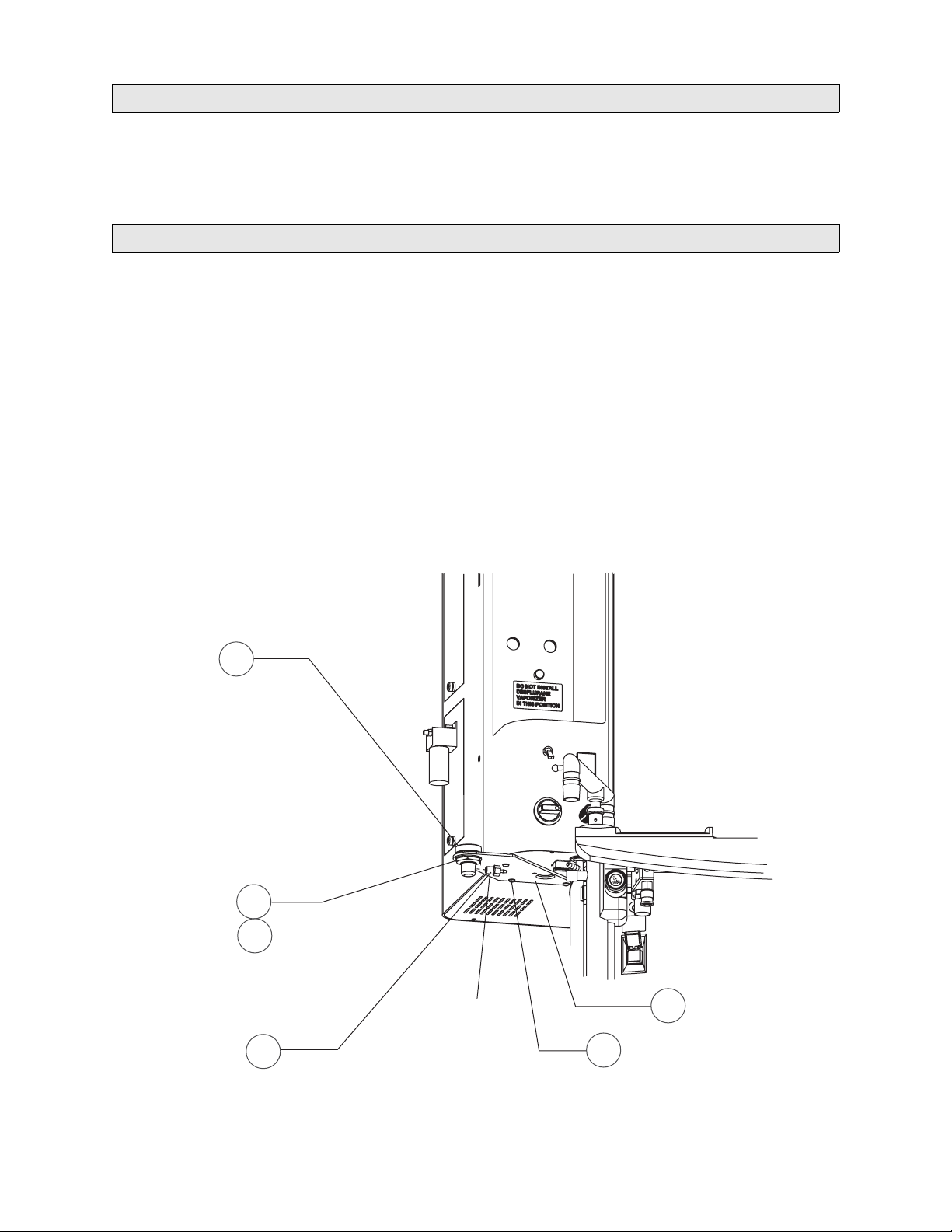
1. Attach the gauge bracket (2) to the
underside of the NM6000 cockpit as
shown in
Figure 1. Remove the existing
screws and use the 8-32 x ½ in. btn hd
screws (13) supplied in the kit, with the
original lock washers.
3
GAUGE MOUNT
2. Install the gauge mount (3) in the
bracket, oriented with the side port
facing the machine. Secure the gauge
mount with the 7/8 jam nut (5) and lock
washer (4) supplied in the kit.
3. Install the 1/8 NPT x 1/8 hose barb
fitting (7) in the side port of the gauge
mount. Use a small amount of Loctite
#271 (red) on the threads.
SP22301
7/8 LOCKWASHER
7/8 JAM NUT
1/8 NPT X 1/8 HOSE
BARB FITTING
4
5
7
FIGURE 1. Gauge Mount Assembly
*R
*R = LOCTITE #271 (RED)
1
2
GAUGE BRACKET
GAUGE BRACKET SCREWS (3X)
13
& ORIGINAL LOCKWASHERS (3X)
Page 4

Installation Procedure (continued)
RETURN TO SERVICE PROCEDURE TABLE OF CONTENTS
RETURN TO CD-ROM TABLE OF CONTENTS
4. Assemble the chrome T-fitting (10), 1/8
MPT Qdisc-M fitting (12), 1/8 NPT
Qdisc-F fitting (11), and 1/8 NPT x 1/8
*R
*R
hose barb fitting (7) as shown in
2. Use a small amount of Loctite #271
(red) on the threads of all fittings.
Q DISC-M X 1/8 MPT FITTING
12
Q DISC W/VALVE-F
11
*R
X 1/8 NPT FITTING
Figure
SP22302
FIGURE 2. T-A ss e mb ly
*R = LOCTITE #271 (RED)
10
CHROME T-FITTING
1/8 NPT X 1/8 HOSE BARB
7
FITTING
2
Page 5

Installation Procedure (continued)
RETURN TO SERVICE PROCEDURE TABLE OF CONTENTS
RETURN TO CD-ROM TABLE OF CONTENTS
5. Place a hose clamp (6) on each end of the
23 in. long piece of clear hose (9)
supplied in the kit.
6. Attach one end of the hose to the hose
barb on the gauge mount. Attach the
other end to the hose barb on the Tassembly. Secure both ends with the
hose clamps. See
Figure 3.
7. Install two stick-on cable clamps (8) in
the approximate locations shown in the
illustration. Route the tubing as shown.
SP22303
HOSE CLAMP
STICK-ON
CABLE CLAMP
23 IN. LONG
CLEAR HOSE
6
8
9
FIGURE 3. Hose Installation
HOSE CLAMP
6
T-ASSEMBLY
3
Page 6

Installation Procedure (continued)
RETURN TO SERVICE PROCEDURE TABLE OF CONTENTS
RETURN TO CD-ROM TABLE OF CONTENTS
8. Install the breathing pressure gauge
assembly (1) on the gauge mount. Orient
the gauge as desired and tighten its
locking ring.
9. Disconnect the existing airway pressure
hose from the patient interface panel
and connect it to the T assembly as
shown in
Figure 4.
10. Connect the T assembly to the patient
interface panel as shown in the
illustration.
11. Locate the Operator’s Instruction
Manual binder and insert the
Supplement (P/N 4117388) supplied in
the kit for the breathing pressure gauge
option.
1
BREATHING PRESSURE
GAUGE
SP22304
FIGURE 4. Machine Connections
AIRWAY PRESSURE
HOSE
T-ASSEMBLY
4
Page 7

RETURN TO SERVICE PROCEDURE TABLE OF CONTENTS
RETURN TO CD-ROM TABLE OF CONTENTS
Installation Procedure (continued)
Table 1: Kit, Breathing Pressure Gauge Asm Option (P/N 4117271) Replacement Parts List
ITEM
NUMBER
PART
NUMBER
DESCRIPTION QTY
1 4115272 Gauge Asm, Breathing Pressure 1 EA
2 4117272 Bracket, Pressure Gauge 1 EA
3 4117273 Mount, Pressure Gauge 1 EA
4 4117274 Nut, Jam, 7/8 - 24 1 EA
5 HW67008 Washer, Lock, Int-T, 7/8 SS 1 EA
6 S010236 Clamp, Hose, Reusable 2 EA
7 4117285 Ftg, 1/8 D Barb x 1/8 NPT, Male 2 EA
8 4111933 Clamp, Cable, 1/4 D x 3/4 2 EA
9 ML08007 Hose, Clear, .130ID x .060W 23 IN
10 4110978 Ftg, Tee, 1/8FPT - Chrome 1 EA
11 4114806 QDisc - w/Valve, MX 1/8 NPTM 1 EA
12 4108139 QDisc - w/ Valve, F x 1/8 NPTM 1 EA
UNIT OF
MEASURE
13 HW09002 Scr, Btn Hd Skt, 8-32 x 1/2 L SS 3 EA
N/A 4117388 Supplement 1 EA
5
Page 8

RETURN TO SERVICE PROCEDURE TABLE OF CONTENTS
RETURN TO CD-ROM TABLE OF CONTENTS
Page 9

RETURN TO SERVICE PROCEDURE TABLE OF CONTENTS
RETURN TO CD-ROM TABLE OF CONTENTS
Page 10

RETURN TO SERVICE PROCEDURE TABLE OF CONTENTS
RETURN TO CD-ROM TABLE OF CONTENTS
DrägerService is a division of
Draeger Medical, Inc.
3122 Commerce Drive
Telford, PA 18969
Tel: (215) 721-5402
(800) 543-5047
Fax: (215) 721-5784
Web: www.draegermedical.com
Printed in the U.S.A.
 Loading...