

Page 1

RETURN TO SERVICE PROCEDURE TABLE OF CONTENTS
RETURN TO CD-ROM TABLE OF CONTENTS
Kit, AV2+ Ventilator
Upgrade for Narkomed 2C
INSTALLATION PROCEDURE
The following procedure applies to Narkomed 2C machines with an AV2 ventilator, and provides
the instructions needed to install an AV2+ ventilator controller and its interface cables.
Removing the AV2 ventilator
controller:
1. Turn the System Power switch to
STANDBY and remove AC power
from the machine.
2. Disconnect all pipeline hoses and
close all cylinder valves.
3. If applicable, remove any optional
second shelf assemblies from the
machine.
CAUTION: The ventilator controller
circuit board contains static
sensitive devices. Use ESD
protection when handling
the controller assembly.
4. Remove the ventilator box top cover
and disconnect its ground wire.
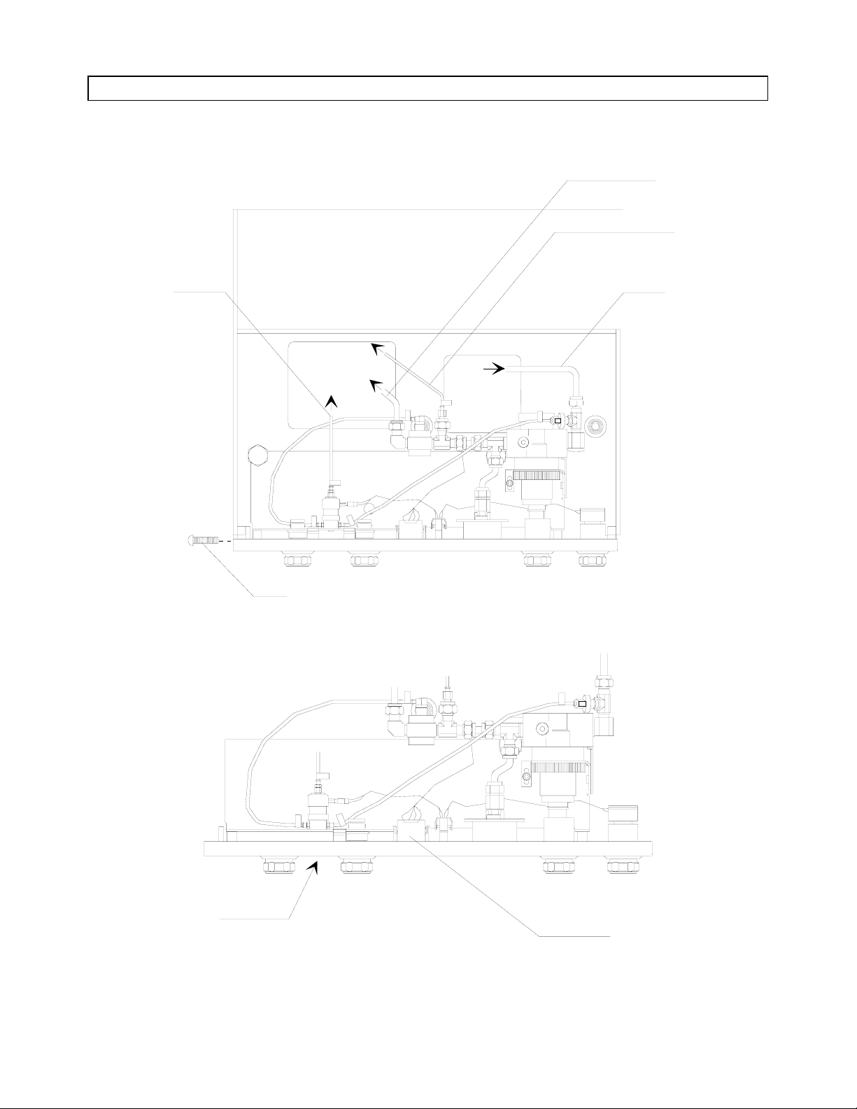
5. Remove the two screws securing the
left end of the ventilator controller
panel. See Figure 1.
6. Pull the left side of the panel
outward, slide it to the left until the
locking tab on the right side of the
panel is clear of its receptacle, then
pull the assembly out far enough to
gain access to its connections.
7. Disconnect the alarm channel
wiring harness from J2 on the
controller circuit board.
8. Disconnect the following large and
small diameter pneumatic tubing
(the letters are keyed to the
illustration):
A: Small dia. tube from
solenoid to rear vent fitting
on bellows box
B: Large dia. tube from supply
valve to venturi
C: Small dia. tube to auto-
ranging valve
D: Large dia. tube from main
switch (O
9. Remove the controller and bezel
assembly from the machine.
supply)
2
1
Page 2
RETURN TO SERVICE PROCEDURE TABLE OF CONTENTS
INSTALLATION PROCEDURE (continued)
SP16201
RETURN TO CD-ROM TABLE OF CONTENTS
TO VENTURI
TO AUTO-
RANGING VALVE
TO VENT
RETAINING
SCREWS (2X)
O2 SUPPLY
TOP VIEW OF
CONTROLLER
ASSEMBLY
IN VENTILATOR
BOX
D
B
C
A
AV2 CONTROLLER
ASSEMBLY
Figure 1: AV2 VENTILATOR CONTROLLER ASSEMBLY REMOVAL
2
J2 (ALARM CHANNEL
WIRING HARNESS)
Page 3
RETURN TO SERVICE PROCEDURE TABLE OF CONTENTS
INSTALLATION PROCEDURE (continued)
Removing the interface panel blank:
RETURN TO CD-ROM TABLE OF CONTENTS
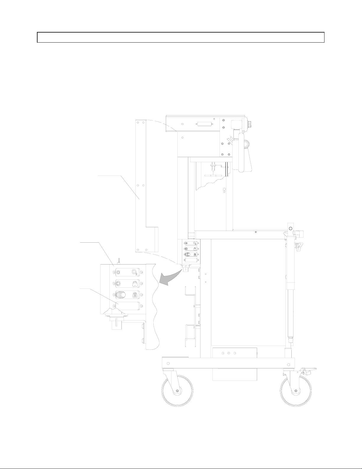
10. At the back of the machine, remove
the cover from the wiring channel
and interface housing. See Figure 2.
WIRING CHANNEL
COVER
(ON OPPOSITE SIDE)
INTERFACE
HOUSING
11. Remove the blank interface panel
from the interface housing.
XXXXX
XXXXX
XXXXX
XXXXX
XXXXX
XXXXX
XXXXX
INTERFACE
XXXXX
PANEL BLANK
(REMOVE)
SP16202
LEFT SIDE VIEW
Figure 2: INTERFACE HOUSING - COVER AND BLANK PANEL REMOVAL
3
Page 4

RETURN TO SERVICE PROCEDURE TABLE OF CONTENTS
INSTALLATION PROCEDURE (continued)
Installing the new selector interface
panel assembly:
12. On the new selector interface panel
assembly (P/N 4113090-001), slide
the bulkhead bushing to the
connector end of the cable and
temporarily tape the bushing to the
cable. See Figure 3.
13. Feed the connector end of the cable
up through the back of the interface
housing and wiring channel up into
the ventilator box.
Continue feeding in the cable until
the new selector interface panel can
be positioned in the interface
housing opening.
RETURN TO CD-ROM TABLE OF CONTENTS
14. Install the new interface panel in
the housing with the hardware that
previously retained the blank panel.
15. Remove the ground lug retaining
nut (see Figure 3). Install the
interface panel ground lug on the
stud, add a #6 ext-t lock washer
(P/N HW68000) and reinstall the
retaining nut.
16. Reinstall the wiring channel cover.
4
Page 5

RETURN TO SERVICE PROCEDURE TABLE OF CONTENTS
INSTALLATION PROCEDURE (continued)
VENTILATOR BOX
WIRING CHANNEL
GROUND LUG
RETAINING NUT
RETURN TO CD-ROM TABLE OF CONTENTS
BULKHEAD
BUSHING
GROUND WIRE
(INSTALL UNDER
GROUND LUG
RETAINING NUT
W/LOCK WASHER)
SP16203
Figure 3: INTERFACE PANEL AND CABLE INSTALLATION
5
CABLE (ROUTE UP THROUGH
WIRING CHANNEL AND
INTO VENTILATOR BOX)
SELECTOR INTERFACE PANEL
(INSTALL IN PLACE
OF BLANK PANEL)
Page 6

RETURN TO SERVICE PROCEDURE TABLE OF CONTENTS
INSTALLATION PROCEDURE (continued)
Routing the cable in the ventilator
box:
RETURN TO CD-ROM TABLE OF CONTENTS
17. Examine the bulkhead in the
ventilator box (see Figure 4) and
determine whether Hole "A" is
present.
Skip the next step if the bulkhead
has this threaded hole.
18. If there is no threaded hole in the
bulkhead, proceed as follows:
a) Measure and mark the location
shown in the Figure 4 detail.
b) Tape paper over the openings in the
floor of the ventilator box to
prevent drilling chips from falling
into other areas of the machine.
c) Carefully drill a 33/64 in. dia. hole
(recommended clearance for the ½
in. bushing) at the location marked.
19. Remove the tape that was
previously applied to hold the
bushing at the connector end of the
interface cable.
20. Remove the hex nut from the
bulkhead bushing.
21. Route the connector and cable
through hole "A" in the bulkhead.
22. Thread the bulkhead bushing into
the hole
or, if the hole was drilled,
insert the bushing into the hole and
slide the hex nut (supplied with the
panel and cable assembly) over the
cable and thread it onto the
bushing.
d) Carefully de-burr the hole and
vacuum all drill chips from the
machine. Remove the tape and
paper.
6
Page 7

RETURN TO SERVICE PROCEDURE TABLE OF CONTENTS
INSTALLATION PROCEDURE (continued)
RETURN TO CD-ROM TABLE OF CONTENTS
CABLE
HEX NUT
(REMOVE)
HOLE "A"
BULKHEAD
DETAIL
3/4 IN.
VENTILATOR
BOX
Figure 4: CABLE INSTALLATION IN VENTILATOR BOX
7
Page 8

RETURN TO SERVICE PROCEDURE TABLE OF CONTENTS
INSTALLATION PROCEDURE (continued)
Installing the AV2+ ventilator
controller
RETURN TO CD-ROM TABLE OF CONTENTS
CAUTION: The ventilator controller
circuit board contains static
sensitive devices. Use ESD
protection when handling
the controller assembly.
23. Position the AV2+ controller and
bezel assembly (P/N 4113132-S01)
in the ventilator box and connect
the four pneumatic lines: A, B, C,
and D. See Figure 5.
24. Connect the alarm channel wiring
harness to J2 on the controller
circuit board, and connect the new
selector interface cable to J7 on the
circuit board.
25. The AV2+ controller and bezel
assembly installs in the ventilator
box in the same manner as the AV2
assembly (ref. Figure 1).
Slide the controller into the
ventilator box, carefully fit the
locking tab into its receptacle at the
right side of the panel, and slide
the assembly to the right until it is
properly seated.
26. Reinstall the two retaining screws
at the left side of the panel.
27. Re-connect the ventilator box top
cover ground wire, and secure the
cover to the ventilator box.
8
Page 9

RETURN TO SERVICE PROCEDURE TABLE OF CONTENTS
INSTALLATION PROCEDURE (continued)
RETURN TO CD-ROM TABLE OF CONTENTS
SELECTOR CABLE
FROM INTERFACE
PANEL
SP16205
B
D
C
A
J7
(SELECTOR CABLE)
Figure 5: INSTALLING THE AV2+ VENTILATOR CONTROLLER
9
J2 (ALARM CHANNEL
WIRE HARNESS)
AV2+ CONTROLLER &
BEZEL ASSEMBLY
Page 10

RETURN TO SERVICE PROCEDURE TABLE OF CONTENTS
INSTALLATION PROCEDURE (continued)
Installing the AUTO/BAG Sensor Cord:
RETURN TO CD-ROM TABLE OF CONTENTS
NOTE: This installation requires
that the machine be
equipped with the new
Man/Auto selector valve
(P/N 4112217-001) in order
to accept the sensor cord.
If your installation has the
earlier design valve, order
kit P/N 4113303 for upgrade
to the new selector valve.
Installation instructions for
the new valve are provided
by Service Procedure
SP00115.
28. Insert the sensor end of the sensor
cord (P/N 4113126) into the
underside of the Man/Auto selector
housing. See Figure 6. Note that
the sensor is keyed and will only fit
into the selector housing one way.
Push the sensor into the selector
housing until it snaps into place.
30. Restore power and O
connections
2
to the machine and verify operation
of the AUTO/BAG sensor as follows:
a) Turn the System Power switch ON.
b) Set the Selector valve to the BAG
position.
c) Turn the Ventilator ON; the fault
lamp shall light.
d) Set the selector valve to the AUTO
position; the fault lamp shall turn
off and the ventilator shall begin
operating.
31. Insert the Operator’s Manual
Supplement (P/N 4113687) into the
operator’s manual binder that
accompanies the machine.
32. Perform a complete PMS procedure
on the machine.
29. Plug the other end of the sensor
cord into the receptacle on the
SELECTOR interface panel on the
machine. Align the key on the
connector with the keyway on the
receptacle, and push the connector
in until it snaps into place.
10
Page 11

RETURN TO SERVICE PROCEDURE TABLE OF CONTENTS
INSTALLATION PROCEDURE (continued)
RETURN TO CD-ROM TABLE OF CONTENTS
SENSOR END
SP16206
MAN/AUTO SELECTOR
SENSOR CORD
SELECTOR
INTERFACE
PANEL
Figure 6: INSTALLING THE AUTO/BAG SENSOR CORD
11
Page 12

NORTH
RETURN TO SERVICE PROCEDURE TABLE OF CONTENTS
RETURN TO CD-ROM TABLE OF CONTENTS
AMERICAN
DRÄGER
Technical Service Department
3122 Commerce Drive
Telford, PA 18969
(215) 721-5402
(800) 543-5047
(215) 723-5935 Fax
Quality Service for Life
®
Part Number: SP00162
Rev: Date: May 1, 1996
© 1996 N.A.D., Inc.
 Loading...