

Page 1

RETURN TO SERVICE PROCEDURE TABLE OF CONTENTS
RETURN TO CD-ROM TABLE OF CONTENTS
Field
Service
Procedure
Part Number: SP00260
Date: 14 February 2003
© 2003 Draeger Medical, Inc.
Rev: -
Kit, APC Power Supply Replacement on
Narkomed Models 4, 3, 2C, 2B, and GS
Page 2

RETURN TO SERVICE PROCEDURE TABLE OF CONTENTS
RETURN TO CD-ROM TABLE OF CONTENTS
Page 3

RETURN TO SERVICE PROCEDURE TABLE OF CONTENTS
RETURN TO CD-ROM TABLE OF CONTENTS
Kit - APC Power Supply Replacement on Narkomed
Models 4, 3, 2C, 2B, and GS
Introduction
This procedure includes instructions for the replacement of the Saturn WPU power supply
(UPS) as related to Narkomed model numbers 4, 3, 2C, 2B, and GS. The APC Power Supply
Kit numbers will vary depending on the model number of the Narkomed Machine. Kit
number 4117870-001 is to be used on the Narkomed 4, 3, and 2C. Kit number 4117870-001
consists of the following parts:
-- Power Supply Assembly, APC P/N 4117859 -- Base, Power Supply P/N 4117869
-- Transformer, P/N 4114985 -- Screw, Button Head P/N HW09005
-- Washer, Lock P/N HW67006 -- Power Cord Asm, 6 FT P/N 4110334
-- Label, P/N 4112866-055 -- Power Cord Asm, 3 FT P/N 4110333
Kit number 4117870-002 is to be used on the Narkomed 2B and GS. Kit number 4117870002 consists of the following parts:
-- Power Supply Assembly, APC P/N 4117859 -- Base, Power Supply P/N 4117869
-- Transformer, P/N 4114985 -- Screw, Button Head P/N HW09005
-- Power Supply Bracket P/N 4115957 -- Washer, Lock P/N HW67006
-- Label, P/N 4112866-056 -- Power Cord Asm, 3 FT P/N 4110333
-- Power Cord Asm, 6 FT P/N 4110334 -- Screw, Button Head P/N HW09013
-- Washer, Lock P/N HW67006 -- Nut, Kep P/N HW55002
NOTE: Ensure the appropriate kit had been obtained prior to beginning the installation
procedures.
The following procedures are divided into two sections. Each section contains detailed
instruction based on the appropriate kit number and Narkomed model number being
modified. Proceed to the appropriate section.
1
Page 4

RETURN TO SERVICE PROCEDURE TABLE OF CONTENTS
RETURN TO CD-ROM TABLE OF CONTENTS
Replacement Procedure
KIT NUMBER 4117870-001 - NARKOMED 4, 3, AND 2C
1. Turn the system power switch to STANDBY.
2. Disconnect AC power from the machine and pull all circuit breakers to their ‘out’
position.
3. Remove the bottom and middle drawers from the machine by sliding them off of the
cabinet rails.
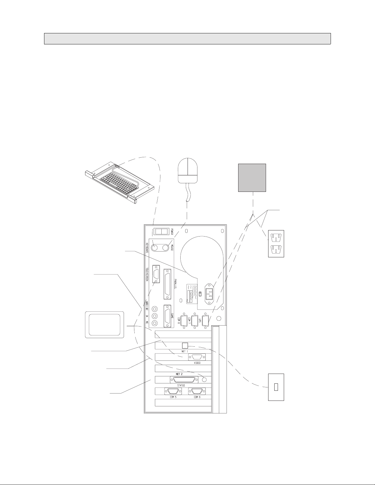
4. Disconnect power supply cables from the Saturn processor. Disconnection of these cables
will depend on the processor installed on the machine. Figures 1, 2, and 3 illustrate the
cable connections for each of the three processor configurations.
5. Unscrew the four captive screws attaching the Saturn power supply to the machine
power supply. Figure 4 illustrates the current Saturn power supply mounting
configuration. Discard old power supply and hardware.
NOTE: The Saturn power supply assembly is assembled and shipped from the factory as a
unit. This assembly will contain the power supply, the transformer, and the label
already mounted on the power supply base.
6. Place the new Saturn power supply assembly flush on top of the Narkomed power supply.
7. Align the Saturn power supply assembly mounting holes with existing holes on the top
portion of the Narkomed power supply.
8. Using a standard allen wrench, attach the new Saturn power supply assembly using four
button head screws and four lock washers. Ensure that A/C outlets are facing the left
side of the machine. See Figure 5.
NOTE: Narkomed 4 model machines will require that cables be routed through corner
notch between power supply assembly base plate and machine frame rails.
9. Reconnect new power supply cables from power supply to processor unit. See Figures 1,
2, and 3 for correct cable connections based on the processor installed.
10. Reinstall bottom and middle drawers into machine.
11. Reconnect AC power to the machine and press circuit breakers into their ‘in’ position.
12. Turn the system power switch to ‘ON’.
13. Verify system power up is successful.
14. If system fails to power up, perform the following:
2
Page 5
RETURN TO SERVICE PROCEDURE TABLE OF CONTENTS
RETURN TO CD-ROM TABLE OF CONTENTS
Replacement Procedure
• Ensure circuit breakers are ‘in’.
• Ensure AC power is applied to the machine.
• Ensure system power switch is in the ‘on’ position.
• Ensure cable connections are correct.
15. If system continues to fail power up, contact your DMIT technical service representative.
KEYBOARD MOUSE
COMMUNICATIONS
TOUCH
CONTROL
MONITOR
POWER SUPPLY
ASSEMBLY
POWER
AC
POWER
(WALL)
VIDEO
DISPLAY
FLAT PANEL
POWER
PROCESSOR
UNIT
SU00538
FIGURE 1. Typical 233 Mhz Processor Cable Connections
3
(WALL)
NETWORK
Page 6

Replacement Procedure
RETURN TO SERVICE PROCEDURE TABLE OF CONTENTS
RETURN TO CD-ROM TABLE OF CONTENTS
KEYBOARD MOUSE
COMMUNICATIONS
TOUCH
CONTROL
MONITOR
POWER SUPPLY
ASSEMBLY
POWER
AC
POWER
(WALL)
VIDEO
DISPLAY
FLAT PANEL
POWER
PROCESSOR
UNIT
SU00060
FIGURE 2. Typical 400 Mhz Processor Cable Connections
4
(WALL)
NETWORK
Page 7

RETURN TO SERVICE PROCEDURE TABLE OF CONTENTS
RETURN TO CD-ROM TABLE OF CONTENTS
Replacement Procedure
KEYBOARD MOUSE
COMMUNICATIONS
TOUCH
CONTROL
MONITOR
POWER SUPPLY
ASSEMBLY
POWER
AC
POWER
(WALL)
VIDEO
DISPLAY
FLAT PANEL
POWER
PROCESSOR
UNIT
SU00061
FIGURE 3. Typical 700 MHZ Processor Cable Connections
5
(WALL)
NETWORK
Page 8

Replacement Procedure
SATURN POWER
SUPPLY
(4116687-001 &002)
RETURN TO SERVICE PROCEDURE TABLE OF CONTENTS
RETURN TO CD-ROM TABLE OF CONTENTS
EXISTING
HARDWARE
NARKOMED
POWER SUPPLY
FRAME
SPACER
MACHINE
SU00034
POWER
SUPPLY
FIGURE 4. Existing Saturn Power Supply Mounting Configurations on Narkomed 4, 3,
and 2C
6
Page 9

RETURN TO SERVICE PROCEDURE TABLE OF CONTENTS
RETURN TO CD-ROM TABLE OF CONTENTS
Replacement Procedure
MACHINE POWER
SUPPLY
NEW SATURN
POWER SUPPLY ASSEMBLY
LOCATION OF NOTCH CUTOUT FOR
NARKOMED 4 CABLE ROUTING
FIGURE 5. Replacement Saturn Power Supply Mounting Configuration on Narkomed 4,
3, and 2C
7
Page 10

RETURN TO SERVICE PROCEDURE TABLE OF CONTENTS
RETURN TO CD-ROM TABLE OF CONTENTS
Replacement Procedure
KIT NUMBER 4117870-002 - NARKOMED 2B AND GS
1. Turn the system power switch to STANDBY.
2. Disconnect AC power from the machine and pull all circuit breakers to their ‘out’
position.
3. Remove the bottom and middle drawers from the machine by sliding them off of the
cabinet rails.
4. Disconnect power supply cables from the Saturn processor. Disconnection of these cables
will depend on the processor installed on the machine. Figures 1, 2, and 3 illustrate the
cable connections for each of the three processor configurations.
5. Position a support device under the existing Saturn power supply located underneath the
Narkomed machine.
6. While supporting the power supply, remove four screws, four flat washers, and four acorn
nuts attaching the power supply to the underside of the Narkomed frame. See Figure 6.
Discard old power supply and attaching hardware.
NOTE: The Saturn power supply assembly is assembled and shipped from the factory as a
unit. This assembly will contain the power supply, the transformer, power supply
brackets with attaching hardware, and the label already mounted on the power
supply base.
7. Place Saturn power supply assembly flush on the top edge of the bottom frame rails.
8. Align mounting holes on lip of Saturn power supply assembly with the existing holes
drilled in frame rail.
9. Using a standard allen wrench, attach the new Saturn power supply assembly using four
button head screws and four lock washers. Ensure that A/C outlets are facing the left
side of the machine. See Figure 7.
10. Connect new cables from power supply to processor unit. See Figures 1, 2, and 3 for
correct cable connections based on the processor installed.
11. Reinstall bottom and middle drawers into machine.
12. Reconnect AC power to the machine and press circuit breakers into their ‘in’ position.
13. Turn the system power switch to ‘ON’.
14. Verify system power up is successful.
15. If system fails to power up, perform the following:
8
Page 11

RETURN TO SERVICE PROCEDURE TABLE OF CONTENTS
RETURN TO CD-ROM TABLE OF CONTENTS
Replacement Procedure
• Ensure circuit breakers are ‘in’.
• Ensure AC power is applied to the machine.
• Ensure system power switch is in the ‘on’ position.
• Ensure cable connections are correct.
16. If system continues to fail power up, contact your DMIT technical service representative.
FLAT WASHER
SATURN
POWER
SUPPLY
(4116690-001 & 002)
ACORN NUT
SCREW HEX
SU26001
FIGURE 6. Existing Saturn Power Supply Mounting Configurations on the Narkomed 2B
and GS
9
Page 12

Replacement Procedure
RETURN TO SERVICE PROCEDURE TABLE OF CONTENTS
RETURN TO CD-ROM TABLE OF CONTENTS
NEW SATURN POWER SUPPLY
NEW SATURN POWER SUPPLY
MOUNTING HARDWARE (TYPICAL FOUR PLACES)
FIGURE 7. Replacement Saturn Power Supply Mounting Configuration on Narkomed 2B
and GS
10
Page 13

RETURN TO SERVICE PROCEDURE TABLE OF CONTENTS
RETURN TO CD-ROM TABLE OF CONTENTS
Page 14

RETURN TO SERVICE PROCEDURE TABLE OF CONTENTS
RETURN TO CD-ROM TABLE OF CONTENTS
DrägerService is a division of
Draeger Medical, Inc.
3122 Commerce Drive
Telford, PA 18969
Tel: (215) 721-5402
(800) 543-5047
Fax: (215) 721-5784
Web: www.draegermedical.com
Printed in the U.S.A.
 Loading...