

Page 1

RETURN TO SERVICE PROCEDURE TABLE OF CONTENTS
RETURN TO CD-ROM TABLE OF CONTENTS
KIT,AIRDISS&CO2YOKE
INSTALLATIONPROCEDURE
NOTE: Thisprocedureoutlinesanextremelycomplexmodificationoftheanesthesia
machine.InstallationofthiskitshallbeperformedonlybyaNorthAmerican
DrägerqualifiedTechnicalServiceRepresentativewiththenecessaryknowledge
andexperience.
NOTE: Thisprocedureappliesto2-gasmachineswithearliertubingarrangements,fluted
flowknobguards,andflowcontrolknobslocatedbelowthe100to1000ml/min.
(fine)flowmeters.
1. TurntheSystemPowerswitchto
ONanddisconnectallpipeline
hoses.
2. Closeallcylindervalvesexceptthe
O
cylindervalve.
2
3. Settheoxygenflowrateto5l/min.
4. OpentheN
Oflowcontrolvalveto
2
drainpressurefromthesystem.
5. ClosetheO
cylindervalve,and
2
closetheflowcontrolvalves.Press
theO
FLUSHbuttontodrain
2
pressurefromthesystem.
6. TurntheSystemPowerswitchto
STANDBYandremoveACpower
fromthemachine.Disableallcircuit
breakers.
7. Removethescrewssecuringthe
tabletop,andremovethetabletop.
CAUTION: Use ESD control when
handling any electronic
componentsorassemblies.
9. Removethevaporboxfrontcover.
FormachineswithaMultispec
analyzer,removeallconnectionsto
thePCBassemblyonthevaporbox
frontplate,andremovethePCB
fromtheplate.
10. Removethevaporboxbackcover.
11. Removethescrewsholdingthe
angledfrontplateatthetopofthe
flowmetershield,andremovethe
plate.
12. Removeallflowcontrolknobs.
13. Removethetwoscrewssecuringthe
knobguard;removetheguardand
theflowmetershield.
8. Removetheflowmeterhousingback
cover.
1
Page 2

RETURN TO SERVICE PROCEDURE TABLE OF CONTENTS
INSTALLATION PROCEDURE (continued)
RETURN TO CD-ROM TABLE OF CONTENTSRETURN TO CD-ROM TABLE OF CONTENTS
CAUTION: Use ESD control when
handling any electronic
components or assemblies.
14. Remove the flowmeter lights PCBs
and channels from the studs on the
O
and N2O flow channels.
2
15. Remove the stop pin hex nuts from
each flow control valve.
16. Remove the flow control valves: hold
each at the wrench flats and turn it
counter-clockwise.
17. Remove each flowmeter tube by
turning its retaining insert at the
top of the assembly counterclockwise until there is enough
clearance to remove the tube from
the channel.
18. Disconnect theflextubing connected
to the N
remove the O
O restrictor housing, and
2
and N2O restrictor
2
assemblies.
19. Remove the cross-over tubes
connecting the O
and N2O fine and
2
coarse flowmeter ports.
24. Remove the three socket head cap
screws securing the bottom
flowmeter block to the channel
assembly.
25. Pull the bottom block forward,
disconnect the small diameter flex
tubing from the block, and remove
the block.
26. Disconnect the flex tubing from the
O
and N2O pipeline gauges.
2
27. Remove the three socket head cap
screws securing the flowmeter
assembly, and remove the assembly.
28. Remove the kep nuts securing the
cylinder and pipeline gauges to the
flowmeter channel and remove the
gauges.
29. Remove the socket head cap screws
securing thetop block to the channel
assembly.
30. Apply masking tape to the raised
surfaces of and the entire inside
area ofthe center flowmeter channel
to prevent scratching.
20. Remove the manifold assembly
connected to the O
and N2O outlets
2
at the top of the flowmeters.
21. Disconnect the 4-way fitting and
restrictor assembly’s lower copper
tube from the O
flowmeter inlet
2
port.
22. Disconnect the copper tube attached
to the N
O flowmeter valve port.
2
23. Disconnect the copper tubes from
the O
and N2O cylinder gauges.
2
31. Temporarilyattach the 4-gas bottom
block to the channel with the screws
that were previously removed from
the original block.
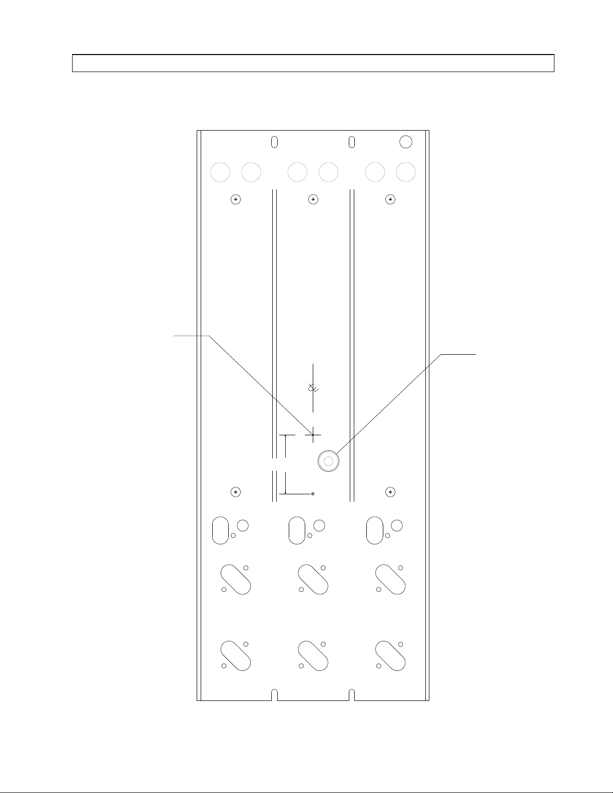
32. Using the bottom block as a
template, mark the circumference of
the 4th gas flow control housing
onto the channel: (Insert a
flowmeter gasket (P/N 4102725) into
the housing. This will provide a
smaller diameter hole to aid in
locating the center point.) The hole
location is shown in Figure 1.
2
Page 3
RETURN TO SERVICE PROCEDURE TABLE OF CONTENTS
INSTALLATION PROCEDURE (continued)
RETURN TO CD-ROM TABLE OF CONTENTSRETURN TO CD-ROM TABLE OF CONTENTS
SP10501
7/64 IN. DIA. HOLE
(DRILL)
11/16 IN. DIA.
CLEARANCE HOLE
(DRILL)
(LOCATE CENTER
USING 4-GAS BLOCK
AND GASKET AS
TEMPLATE)
1 7/8 IN.
Figure 1: DRILLING LOCATIONS: 4-GAS CONVERSION
3
Page 4

RETURN TO SERVICE PROCEDURE TABLE OF CONTENTS
INSTALLATION PROCEDURE (continued)
RETURN TO CD-ROM TABLE OF CONTENTSRETURN TO CD-ROM TABLE OF CONTENTS
33. Remove the 4-gas bottom block and
centering gasket.
CAUTION:
Perform the next four steps in a
suitable location away from the
anesthesia machine to prevent
drilling chips from entering the
pneumatic system.
34. Center punch the marked hole and
drill an 11/16 in. dia. hole into the
flowmeter channel. A hole saw is
recommended. De-burr any sharp
edges.
35. Measure and mark a location 1 in.
up from the lower center spacer
hole, and centered in the channel as
shown in Figure 1.
36. Carefully drill a 7/64 in. dia. hole at
this location, and de-burr any sharp
edges.
37. Remove all masking tape previously
applied, and carefully clean up any
metal chips from the flowmeter
assembly and surrounding area.
38. Using a small amount of Loctite
#271 (red), thread a 3/16 in. tube
straight fitting (P/N 4109402) into
the back of a high pressure gauge
(P/N 4110575-002).
39. Apply a small amount of Loctite
#271 (red) to the threads of a 1/16
in. hose barb (P/N 4111771) and
pipeline pressure gauge (P/N
4110575-001). Assemble the fittings
with coupling (P/N 4103668) as
shown in Figure 2.
4
Page 5
RETURN TO SERVICE PROCEDURE TABLE OF CONTENTS
INSTALLATION PROCEDURE (continued)
RETURN TO CD-ROM TABLE OF CONTENTSRETURN TO CD-ROM TABLE OF CONTENTS
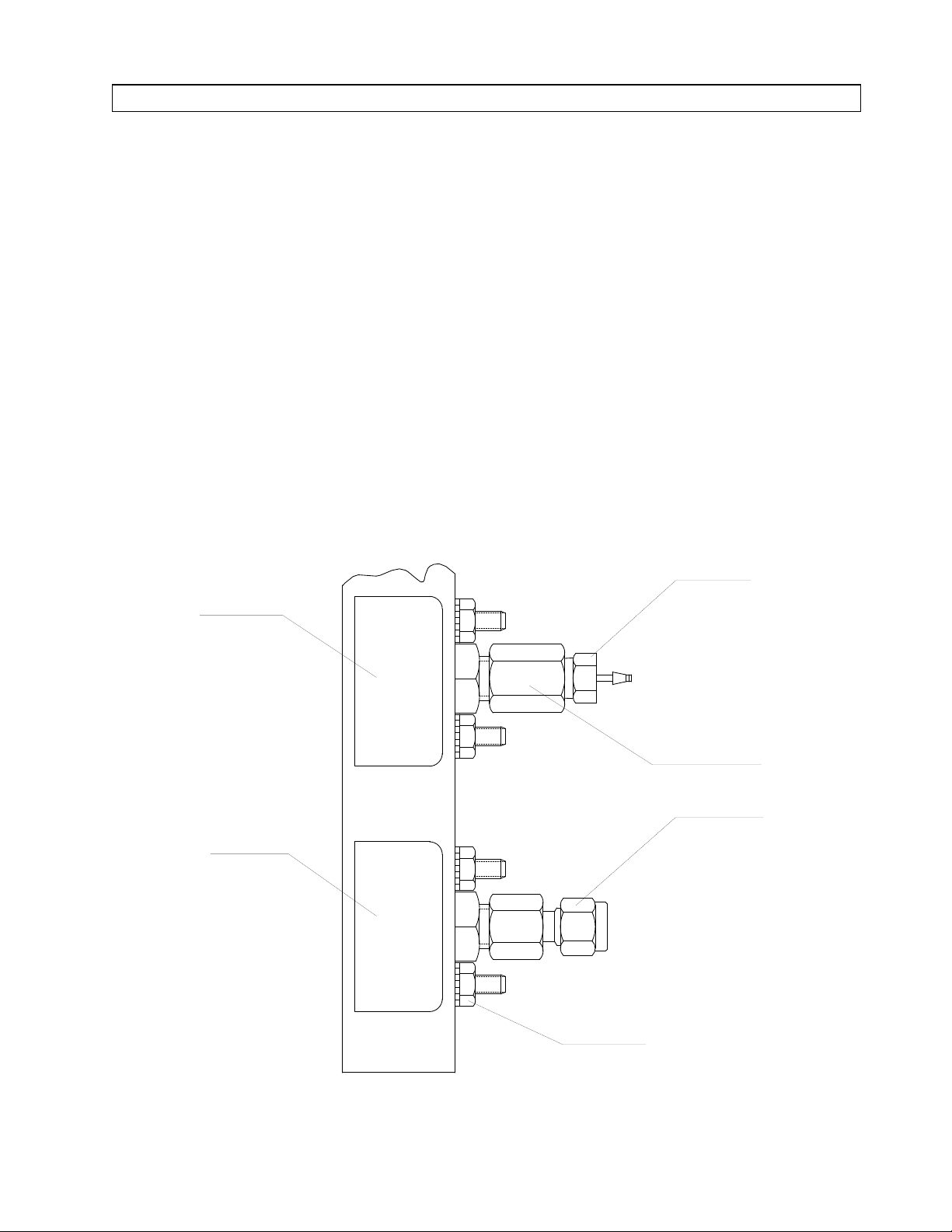
40. Place the pipeline gauge assemblies
into the upper holes of the gauge
channel and secure each gauge with
two 10-32 kep nuts (P/N HW55002
x2). See Figure 2. Reuse the original
hardware to secure the O
and N2O
2
gauges.
FLOWMETER CHANNEL
PIPELINE
PRESSURE
GAUGE
41. Place the cylinder gauge assemblies
SIDE VIEW
into the lower holes of the gauge
channel and secure each gauge with
two 10-32 kep nuts (P/N HW55002
x2). Reuse the original hardware to
secure the O
and N2O gauges.
2
HOSE BARB
SP10502
FITTING
CYLINDER
PRESSURE
GAUGE
GAUGE MOUNTING NUTS
Figure 2: PIPELINE AND CYLINDER GAUGE ASSEMBLY AND MOUNTING
5
COUPLING
STRAIGHT
FITTING
(2X EACH GAUGE)
Page 6

RETURN TO SERVICE PROCEDURE TABLE OF CONTENTS
INSTALLATION PROCEDURE (continued)
RETURN TO CD-ROM TABLE OF CONTENTSRETURN TO CD-ROM TABLE OF CONTENTS
42. Apply a small amount of Loctite
#271 (red) to the threads of two 2-56
x ¼ in. pan head screws (P/N
HW02000 x2). Place a #2 lock
washer (P/N HW67012 x2) on each
screw, and secure the two shoulder
spacers (P/N4110843 x2) to the
inside of the center flowmeter
channel.
43. Reinstall the top block assembly to
the flowmeter channel using the
hardware previously removed.
44. Threadtwo inserts (P/N4102506 x2)
into the center locations of the top
flowmeter block until snug.
45. Secure the 4-gas bottom block (P/N
4110572) to the flowmeter channel
using the hardware previously
removed from the original block.
47. Install a #113 O-ring (P/N 4102792
x4) in the grove of each flowmeter
insert on all four inserts. Apply a
small amount of Parker Super-OLube to these O-rings.
48. Thread the chromed flowmeter
insert into the upper hole of the
bottom block, and the remaining
brass inserts into the lower holes
until snug. DO NOT overtighten the
inserts.
49. Install the flow control valves (P/N
4103352 x2) into the flowmeter
inserts. Reuse the original O
N
O flow control valves. CAUTION:
2
2
and
Before tightening the cartridge,
rotate the valve shaft several turns
counter-clockwise to prevent
bottomingthe valve element into the
seat when the cartridge is tightened.
46. Install a #018 O-ring (P/N 4102336
x4) at the shoulder of each of the
four bottom flowmeter inserts
(consisting of P/N 4110576 x3 and
4110573) as shown in Figure 3.
50. Install the stop pin nuts (P/N
4103382 x2) onto the flow control
assemblies. Reuse the original stop
pin nuts for the O
and N2O
2
assemblies.
51. Thread two 10-32 x 1/16 in. hose
barb fittings w/seal (P/N 4112707001 x2) into the back of the bottom
flowmeter block.
52. Remove the nuts and ferrules from
eight ¼ in. tube straight fittings
(P/N 4109408 x8). Apply a small
amount of Loctite #271 (red) to the
threads of each fitting, and thread
the fittings into the top and bottom
blocks at the locations marked A
Figure 3.
6
Page 7
RETURN TO SERVICE PROCEDURE TABLE OF CONTENTS
INSTALLATION PROCEDURE (continued)
REAR VIEW OF FLOWMETER CHANEL
RETURN TO CD-ROM TABLE OF CONTENTSRETURN TO CD-ROM TABLE OF CONTENTS
SP10503
AA
HOSE BARB
FITTING W/SEAL
BOTTOM BLOCK
MOUNTING SCREWS (3X)
STOP PIN
NUT
FLOW CONTROL
VALVE
A
AA AAA
DETAIL OF FLOW CONTROL
INSERT ASSEMBLY
CROSS-OVER
TUBES (2X)
HOSE BARB
FITTING W/SEAL
(SIDE VIEW)
O-RING, #113
INSERT
O-RING, #018
Figure 3: INSTALLATION OF FITTINGS AND FLOW CONTROL VALVE INSERT ASSEMBLY
7
Page 8

RETURN TO SERVICE PROCEDURE TABLE OF CONTENTS
INSTALLATION PROCEDURE (continued)
RETURN TO CD-ROM TABLE OF CONTENTSRETURN TO CD-ROM TABLE OF CONTENTS
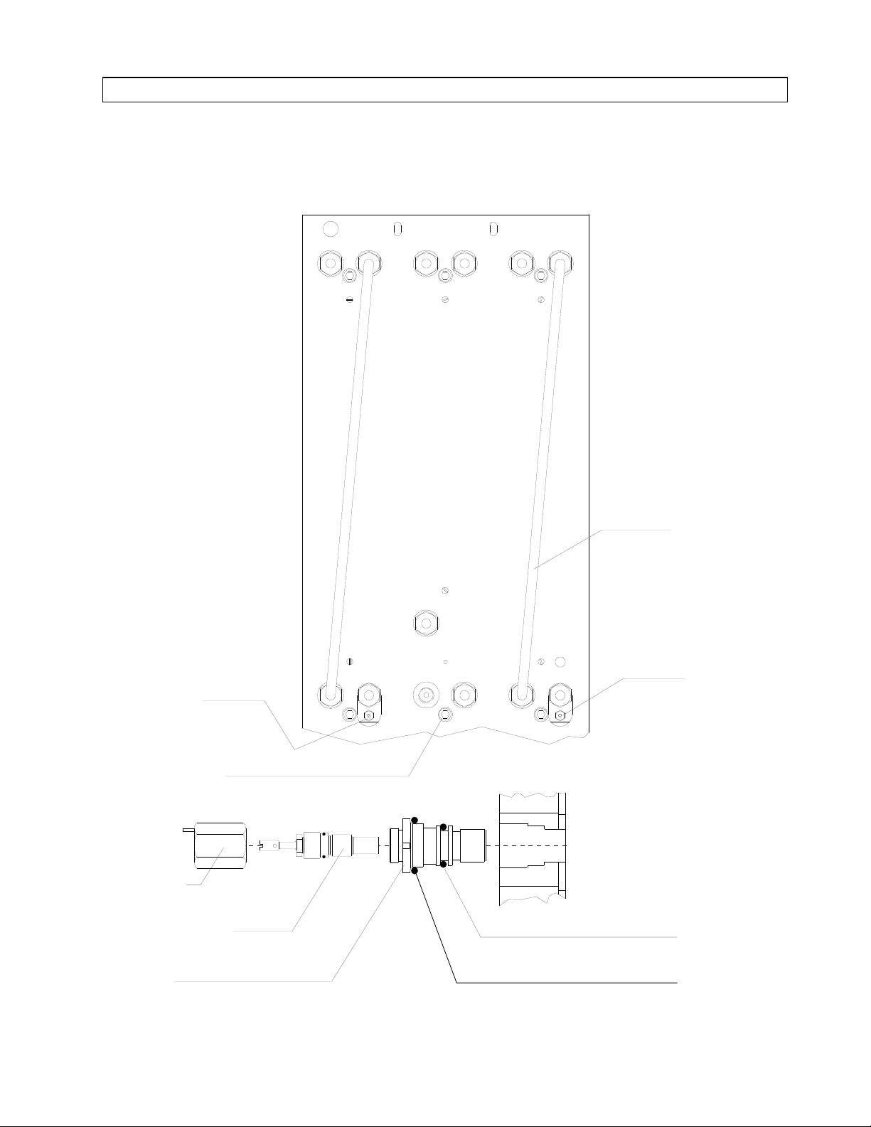
53. Assemble the compression fittings
onto the open ended tubes on the 4gas manifold assembly (consisting of
P/Ns 4108483, 4109408 x4,4109410,
4110834-009 x3, and 4110837-013
x2) as shown in Figure 5. Ensure
that the Swagelok fittings with the
two-piece ferrules are assembled as
shown in Figure 4.
TWO-PIECE
FERRULE
Figure 4: ASSEMBLY OF SWAGELOK FITTINGS
Insert the copper tubes into the
manifold assembly as shown in
Figure 5. Before tightening the
compression nuts, ensure that the
tubing is inserted into the fittings as
far as possible.
COPPER
TUBING
COMPRESSION
NUT
SP10504
54. Attach the copper tubes on the
manifold assembly on the ports at
the top of the flowmeter bank as
shown in Figure 5. Ensure that the
tubing is inserted into the fittings as
far as possible, and tighten the
compression nuts.
O2
MIX
55. Attach the correct gas-identifying
label (P/N 4109871, 4109872,
4109873, 4109874, and 4109901) to
each tube on the manifold assembly
as shown in Figure 5.
SP10505
N20
AIR
MANIFOLD
TOP VIEW
Figure 5: FOUR GAS MANIFOLD ASSEMBLY WITH LABELS
8
CO2
Page 9
RETURN TO SERVICE PROCEDURE TABLE OF CONTENTS
INSTALLATION PROCEDURE (continued)
RETURN TO CD-ROM TABLE OF CONTENTSRETURN TO CD-ROM TABLE OF CONTENTS
56. Reinstall the flowmeter channel
assembly using the hardware
previously removed.
57. Reinstall the cross-over tubes
connecting the oxygen and nitrous
oxide fine and coarse flowmeters.
Verify that the correct identification
labels are attached to each tube.
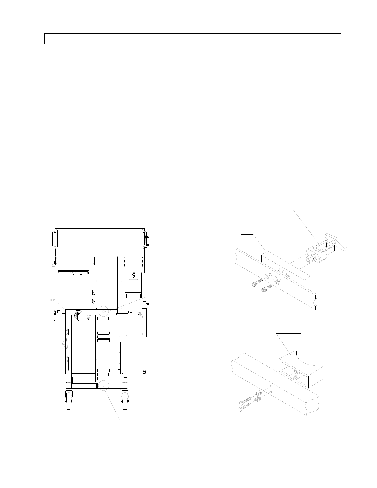
58. Mount the cylinder support (P/N
4106690) on the bottom frame rail at
the back of the machine (see Figure
6) using two ¼-20 x 2½ in. hex head
screws (P/N HW08009 x2), lock
washers (P/N HW65010 x2) and flat
washers (P/N HW66004 x2).
REAR VIEW
59. Mount the CO
(consisting of P/Ns 4111792,
HW06006, 1101624, 4104716,
4105929 x2, and 4112755-001), (and
spacer block (P/N 1101593) on
earlier models) on the upper frame
rail of the machine as shown in
Figure 6. Use two 5/16-24 x 1¾ in.
socket head screws (P/N HW01058
x2) andlock washers (P/N HW65005
x2). Apply a CO
1101639) on this yoke.
YOKE ASSEMBLY
CO2
SPACER
yoke assembly
2
label (P/N
2
YOKE
MOUNTING
LOCATION
SP10506
CYLINDER SUPPORT
MOUNTING LOCATION
Figure 6: CO2YOKE AND CYLINDER SUPPORT MOUNTING LOCATIONS
9
CYLINDER
SUPPORT
Page 10

RETURN TO SERVICE PROCEDURE TABLE OF CONTENTS
INSTALLATION PROCEDURE (continued)
RETURN TO CD-ROM TABLE OF CONTENTSRETURN TO CD-ROM TABLE OF CONTENTS
60. Position the CO
cylinder pressure
2
regulator assembly (consisting of
P/Ns 4103591, 4109415, 4102906x2,
4109409, and 4109401) as shown in
Figure 7, with the Inlet marking
toward the front of the machine.
61. Install two 10-32 x ½ in. set screws
(P/N HW10001 x2) in the regulator
mounting bracket and secure the
regulator.
62. Connect a 3/16 in. dia. (P/N
4104215) pre-bent copper tube
between the CO
the inlet fitting on the CO
cylinder yoke and
2
cylinder
2
regulator.
TOP VIEW OF MACHINE
Ensure that the tubing is inserted
into the ferrules correctly, and
tighten the fittings securely. Install
aCO
label (P/N 4109873 x2) on
2
each end of this tube.
63. Connect a 3/16 in. dia. (P/N
4104214) pre-bent copper tube
between the CO
cylinder gauge and
2
the port marked "HP" on the CO
cylinder regulator. Ensure that the
tubing is inserted correctly, and
tighten the fittings securely. Install
aCO
(P/N 4109873 x2) label on
2
each end of this tube.
2
CO2
CYLINDER
YOKE
3/16 IN. DIA.
COPPER TUBE
SP10507
3/16 IN. DIA. COPPER TUBE
TO CYLINDER PRESSURE GAUGE
"HP"
PORT
SET
SCREWS (2X)
CO2 CYLINDER
PRESSURE
REGULATOR
"INLET" PORT
Figure 7: CO2CYLINDER REGULATOR MOUNTING AND H.P. CONNECTIONS
10
Page 11

RETURN TO SERVICE PROCEDURE TABLE OF CONTENTS
INSTALLATION PROCEDURE (continued)
RETURN TO CD-ROM TABLE OF CONTENTSRETURN TO CD-ROM TABLE OF CONTENTS
64. Reattach the copper tubespreviously
removed from the O
and N2O
2
cylinder gauges, and tighten the
fittings securely. Verify that the gas
identification labels are correct.
65. Reattach the ¼ in. dia. copper tubes
previously removed from the O
N
O flow control valve ports and the
2
2
and
top flowmeter blocks, and tighten
the fittings securely.
66. Remove the ¾ in. dia. plastic plug
from the flowmeter housing directly
abovethe O
pipelineinlet assembly.
2
67. Install a DISS air inlet housing
assembly (consisting of P/Ns
4113363 and 4102886) in the hole
where the plug was removed, using
a -18 hex nut (P/N HW52002) and
lock washer (P/N HW67001). Orient
the DISS connector at a 70° angle as
shown in Figure 8. Apply an AIR
label (P/N 4102742) to the inlet
housing.
68. Apply a small amount of Loctite
#271 (red) to the threads of the filter
assembly (consisting of P/Ns
4102532 and 4106897) and install it
into the air inlet housing.
69. Apply a small amount of Loctite
#271 (red) to the threads of tee
fitting (P/N 4102760). Install it into
the filter assembly as shown in
Figure 8, with its side port facing
downward.
70. Apply a small amount of Loctite
#271 (red) to the threads of a NPT
x 1/16 in. hose barb fitting (P/N
4111771). Install it into the end port
of the tee as shown in Figure 8.
71. Remove the nut and ferrules from ¼
in. tube to NPT elbow fitting (P/N
4109410). Using a small amount of
Loctite #271 (red) install it in the
remaining port as shown in Figure
8. Reattach the nut and ferrules on
the fitting (ref. Figure 4).
72. Install an 8 in.length of flex tubing
(P/N ML08003 x8) between the air
pipeline gauge and the hose barb
fitting installed in the previous step.
Secure each end of the tubing with a
press-on clamp (P/N 4104161 x2),
and install an AIR label (P/N
4109872 x2) on each end of this
tube.
73. Reattach the flex tubing previously
removed from the O
and N2O
2
pipeline gauges. Secure the
connections with the press-on
clamps previously removed (use tie
straps P/N 4106068 x2 for early
style nylon fitting), and verify that
the gas identification labels are
correct.
74. Remove the ¼ in. x 10-32 plug from
the left port of the 4-way fitting and
restrictor assembly, and insert a 1032 x 1/16 in. hose barb fitting w/seal
(P/N 4112707-001) into this port.
11
Page 12

RETURN TO SERVICE PROCEDURE TABLE OF CONTENTS
INSTALLATION PROCEDURE (continued)
RETURN TO CD-ROM TABLE OF CONTENTSRETURN TO CD-ROM TABLE OF CONTENTS
SP10508
SIDE VIEW
FILTER
AIR INLET
HOUSING
O
70
ELBOW
FITTING
REAR VIEW
TEE FITTING
HOSE BARB FITTING
PRESS-ON
HOSE CLAMP (2X)
FLEX TUBING
AIR LABEL (2X)
Figure 8: AIR PIPE LINE INLET ASSEMBLY
12
Page 13

RETURN TO SERVICE PROCEDURE TABLE OF CONTENTS
INSTALLATION PROCEDURE (continued)
RETURN TO CD-ROM TABLE OF CONTENTSRETURN TO CD-ROM TABLE OF CONTENTS
75. Connect the short end of a ¼ in. dia.
"L" tube (P/N 4110837-015) to the
CO2cylinder pressure regulator as
shown in Figure 9. Install a CO
label (P/N 4109873 x2) on each end
of this tube.
76. Connect the other end of the "L"
tube to a ¼ in. T fitting (P/N
4108636), and install a ¼ in. plug
(P/N 4103072) in the side port of the
T fitting, and tighten the fittings
securely.
77. Connect the short end of a ¼ in.dia.
pre-bent tube (P/N 4110279) to the
remaining port on the tee fitting as
2
shown in Figure 9. Install a CO
2
label (P/N 4109873 x2) on each end
of this tube.
SP10509
1/4 IN. DIA. TUBE
TO CO2 OFPD
PLUG
Figure 9: CO2CYLINDER REGULATOR L.P. CONNECTIONS
1/4 IN. DIA.
"L" TUBE
TEE FITTING
13
Page 14

RETURN TO SERVICE PROCEDURE TABLE OF CONTENTS
INSTALLATION PROCEDURE (continued)
RETURN TO CD-ROM TABLE OF CONTENTSRETURN TO CD-ROM TABLE OF CONTENTS
78. Connect either end of a ¼ in.dia. S
tube (P/N 4110836-006) to the CO
flow control valve port. See Figure
10. Install a CO
label (P/N 4109873
2
x2) on each end of this tube.
79. Position the CO
OFPD (consisting
2
of P/Ns 4111771, 4103681, 4102713,
4109408, and 4109410) in the
flowmeter housing and connect the
side fitting on the OFPD to the
previously installed S tube from the
CO
flow control valve. Tighten the
2
fittings securely
80. Connect the bottom fitting on the
CO
OFPD to the copper tube from
2
the CO
regulator that was
2
previously installed. Tighten the
fittings securely.
81. Position the Air OFPD (consisting of
2
P/Ns 4111771, 4103681, 4102713,
4102784, 4015815, and 4109410 x2)
in the flowmeter housing and
connectan Stube (P/N4110836-004)
between the Air flow control valve
and the side fitting on the OFPD.
Tighten the fittings securely. See
Figure 10. Install an AIR label (P/N
4109872 x2) on each end of this
tube.
82. Connect a copper tube (P/N
4108803) between the air pipeline
inlet assembly elbow fitting and the
elbow fitting at the lower end of the
check valve on the Air OFPD, and
tighten the fittings securely. Install
an AIR label (P/N 4109872 x2) on
each end of this tube.
83. Attach the minimum flow cutoff
valve assembly (consisting of P/Ns
4111771, 4102055, 4110792-013,
4103549,and 4112707-001 x2) to the
N
O flowmeter crossover tube with
2
two tie straps (P/N 1101732 x2) as
shown in Figure 10.
14
Page 15

RETURN TO SERVICE PROCEDURE TABLE OF CONTENTS
INSTALLATION PROCEDURE (continued)
RETURN TO CD-ROM TABLE OF CONTENTSRETURN TO CD-ROM TABLE OF CONTENTS
TIE STRAP (2X)
MINIMUM FLOW
CUTOFF VALVE
SP10510
FROM CO2
FLOW CONTROL
VALVE
FROM AIR
FLOW CONTROL
VALVE
AIR OFPD
CO2 OFPD
FROM CO2
REGULATOR
FROM AIR PIPELINE INLET
Figure 10: OFPD AND MINIMUM FLOW VALVE INSTALLATION
15
Page 16

RETURN TO SERVICE PROCEDURE TABLE OF CONTENTS
INSTALLATION PROCEDURE (continued)
RETURN TO CD-ROM TABLE OF CONTENTSRETURN TO CD-ROM TABLE OF CONTENTS
84. Mount the gas selector valve
(consisting of P/Ns 4112707-001 x4,
HW02028 x2, 4108749 x2, 4103621
x2, and 4110518) to the floor of the
vapor box, oriented as shown in
Figure 11, with two 10-32 x 5/16 in.
socket head screws (P/N HW01022
x2), lock washers (P/N HW67006 x2)
and flatwashers (P/N HW66003 x2).
NOTE:
Skip the next nine steps if the
ORMC does not have a wire harness
and switch.
85. Securethe pressureswitch assembly
(consisting of P/Ns 4103444,
4106367, and 4112707-001 x2 to the
copper tubing in the vapor box with
two tie straps (P/N 1101732 x2) as
shown in Figure 11.
86. Disconnect all wires from the ORMC
wire harness adapter.
87. Attach the female connector of the
ORMC wire harness adapter to the
terminal on the right side of the
pressure switch.
88. Attach the female connectors of the
AIR OPT/PRESS SW wire harness
(P/N 4106324) to the male
connectors on the wire harness
adapter.
89. Connect the WHT/YEL wire from
the ORMC to the AIR OPT/PRESS
SW wire harness.
90. Connect the WHT wire from the
alarm channel to the remaining
terminal on the AIR OPT/PRESS
SW wire harness.
SP10511
TO 4-WAY
FITTING
PORT "A"
TO AIR OFPD
TO MINIMUM
FLOW VALVE
FROM
ALARM
CHANNEL
FROM ORMC
WH/YEL
WH
WH/YEL
VAPOR BOX
TOP VIEW
NYLON TEE
FITTING
GAS SELECTOR
VALVE ASSEMBLY
PRESSURE SWITCH
ASSEMBLY
Figure 11: GAS SELECT VALVE AND PRESSURE SWITCH CONNECTIONS
16
Page 17

RETURN TO SERVICE PROCEDURE TABLE OF CONTENTS
INSTALLATION PROCEDURE (continued)
RETURN TO CD-ROM TABLE OF CONTENTSRETURN TO CD-ROM TABLE OF CONTENTS
91. Connect the WHT/YEL wire from
the alarm channel harness to the
remaining terminal on the pressure
switch assembly.
92. Install a 16 in. length of flex tubing
(P/N ML08003 x16) between the
right side port of the pressure switch
and the front port on the gas
selector switch assembly. Secure
each end of the tubing with a presson clamp (P/N 4104161 x2). Install
an O
label (P/N 4109871 x2) on
2
each end of this tube.
93. Connect a 14 in. length of flex
tubing (P/N ML08003 x14) to the
left side port of the pressure switch
in the vapor box, and secure it with
a press-on clamp. Connect the other
end of the tubing to the top hose
barb on the minimum flow valve
and secure it with a press-on clamp
(P/N 4104161 x2). Install an O
label
2
(P/N 4109871 x2) at each end of this
tube.
NOTE: Skip the next step if the
ORMC has a wire harness
and switch.
94. Connect a 33 in. length of flex
tubing (P/N ML08003 x33) between
the front port on the gas selector
switch and secure it with a press-on
clamp. Connect the other end of the
tubing to the top hose barb on the
minimum O
flow valve and secure
2
it with a press-on clamp (P/N
4104161 x2). Install an O
label (P/N
2
4109871 x2) at each end of this tube.
95. Connect an 8 in. length of flex
tubing (P/N ML08003 x8) from the
side port of the rear valve on the gas
selector and secure it with a presson clamp (P/N 4104161). Connect
the other end of the tubing to the
center port of the nylon tee fitting
(P/N 4102337), and secure it with a
tie strap (P/N 4106068). Install an
O
label (P/N 4109871 x2) on each
2
end of this tube.
96. Connect an 11 in. length of flex
tubing (P/N ML08003 x11) to the
side port of the front valve on the
gas selector, and secure it with a
press-on clamp (P/N 4104161).
Connect the other end of the tubing
to the nylon tee fitting installed in
the previous step, and secure the
connection with a tie strap (P/N
4106068). Install an O
label (P/N
2
4109871 x2) on each end of this
tube.
97. Connect a 24 in. length of flex
tubing (P/N ML08003 x24) from the
rear port on the gas selector
assembly to the hose barb on the top
of the air OFPD in the flowmeter
housing. See Figures 11 and 12.
Secure each end with a press-on
clamp (P/N 4104161 x2). Install an
O
label (P/N 4109871 x2) on each
2
end of this tube.
98. Cut the flex tubing two inches above
the hose barb on the top of the air
OFPD and install a nylon tee fitting
(P/N 4102337) as shown in Figure
12. Install an O
label (P/N 4109871
2
x2) on each end of this junction.
17
Page 18

RETURN TO SERVICE PROCEDURE TABLE OF CONTENTS
INSTALLATION PROCEDURE (continued)
FROM PRESSURE
SWITCH ASSEMBLY
RETURN TO CD-ROM TABLE OF CONTENTSRETURN TO CD-ROM TABLE OF CONTENTS
FROM TEE
FITTING
IN VAPOR BOX
TEE FITTING "C"
(EXISTING)
4-WAY
FITTING
FROM GAS
SELECTOR
TEE FITTING
(INSTALL)
2 IN. LENGTH
6 IN. LENGTH
N2O OFPD
AIR OFPD
SP10512
Figure 12: FLEX TUBING CONNECTIONS
CO2 OFPD
18
Page 19

RETURN TO SERVICE PROCEDURE TABLE OF CONTENTS
INSTALLATION PROCEDURE (continued)
RETURN TO CD-ROM TABLE OF CONTENTSRETURN TO CD-ROM TABLE OF CONTENTS
99. Connect a 6 in. length of flex tubing
(P/N ML08003 x6) to the side port of
the nylon tee installed in the
previous step.Connect the other end
of this tube to hose barb on the top
of the CO
OFPD, and secure this
2
connection with a press-on clamp
(P/N 4104161). Secure all nylon tee
fitting junctions with tie straps (P/N
4106068 x3). Install an O
label (P/N
2
4109871 x2) on each end of the
tubing.
100. Connect a 17 in. length of flex
tubing (P/N ML08003 x17) from the
remaining port of the nylon tee
fitting in the vapor box and secure it
with a tie strap (P/N 4106068).
Connect the other end of the tubing
to the side port "A" on the 4-way
fitting and secure it with a press-on
clamp (P/N 4104161). Install an O
label (P/N 4109871 x2) on each end
of this tube. See Figure 12.
101. Remove the existing tubing from
side port "B" on the 4-way fitting.
Connect an 8 in. length of flex
tubing (P/N ML08003 x8) from side
port "B" on the 4-way fitting to the
bottom port of the minimum flow
valve, and secure each connection
with a press-on clamp (P/N 4104161
x2). Install an O
label (P/N
2
4109871 x2) on each end of this
tube. See Figure 12.
102. Cut the tie strap securing the flex
tubing on the side port of tee fitting
"C" in the flowmeter housing and
remove the tubing.
103. Connect a 10 in. length of flex
tubing (P/N ML08003 x10) to the
side port of nylon tee fitting "C", and
secure it with a tie strap (P/N
4106068). Connect the other end of
the tubing to the side port of the
minimum flow valve, and secure it
with a press-on clamp (P/N
4104161). Install an O
label (P/N
2
4109871 x2) on each end of this
tube.
104. Reconnectthe flex tubing previously
removed from the hose barb located
below the O
flow control valve, and
2
secure the connection with the
press-on clamp previously removed.
Verify that an O
label is attached to
2
each end of this hose.
105. Reconnectthe flex tubing previously
2
removed from the hose barb located
below the N
O flow control valve,
2
and secure the connection with the
press-on clamp previously removed.
Verify that a N
O label is attached
2
to each end of this hose.
106. ConnecttheAir pipeline supplyhose
to the machine.
107. Install a CO
cylinder in the new
2
yoke. Verify the presence of two
index pins on the yoke assembly and
the correct engagement with the
cylinder index holes. Open one
cylinder valve each of Oxygen,
Nitrous Oxide and CO
108. Close the N
O flow control valve;
2
.
2
ensure that all other valves are fully
open.
19
Page 20

RETURN TO SERVICE PROCEDURE TABLE OF CONTENTS
INSTALLATION PROCEDURE (continued)
RETURN TO CD-ROM TABLE OF CONTENTSRETURN TO CD-ROM TABLE OF CONTENTS
109. Turn the System Power switch ON,
and depress the rear gas selector
valve to flush any debris from the
new piping, and return the switch to
the STANDBY position.
110. Install the CO
restrictor housing
2
(P/N 4103440) with a yellow
restrictor (P/N 4110738-006) and Oring (P/N 4101872) as shown in
Figure 14.
111. Place gaskets (P/N 4102724 x2) on
top of the CO
restrictor housing and
2
in the insert at the top flowmeter
block for CO
112. Carefully install the CO
.
2
flowtube
2
(P/N 4112557-001) with the CO
marking facing forward as shown in
Figure 14.
113. Install the AIR restrictor housing
(P/N 4103440) with an O-ring (P/N
4101872) as shown in Figure 14.
114. Place gaskets (P/N 4102724 x2) on
top of the AIR restrictor housing and
in the insert at the top flowmeter
block for AIR.
115. Carefully install the AIR flowtube
(P/N 4112558-001) with its AIR
marking facing forward as shown in
Figure 14.
116. Close the AIR and CO
flow control
2
valves.
117. Reinstall the O
restrictor assembly
2
that was previously removed from
the bottom flowmeter block.
119. Turn the System Power switch to
ON to flush any debris from the new
piping, and return the switch to the
STANDBY position.
120. Carefully reinstall the O
flowtube with the O
marking facing
2
2
coarse
forward as shown in Figure 14.
121. Turn the System Power switch ON
to flush any debris from the new
piping, and return the switch to the
STANDBY position.
122. Reconnectthe flex tubing previously
removed from the N
O restrictor
2
assembly and verify that the
connection is secured with a press-
2
123. Reinstall the N
on clamp.
O restrictor
2
assembly that was previously
removed from the bottom flowmeter
block.
124. Turn the System Power switch ON.
Set the O
N
O flow control valve fully to its
2
flow to 4 l/min. Open the
2
stop to flush any debris from the
new piping. Return the System
Power switch to STANDBY.
125. Carefully reinstall the N
flowtube with the N
O fine
2
O marking
2
facing forward as shown in Figure
14.
126. Turn the System Power switch ON
to flush any debris from the new
piping, and return the switch to the
STANDBY position. Close the N
O
2
flow control valve.
118. Carefully reinstall the O
flowtube with the O
marking facing
2
forward.
fine
2
20
Page 21

RETURN TO SERVICE PROCEDURE TABLE OF CONTENTS
INSTALLATION PROCEDURE (continued)
SP10513
GASKET
RETURN TO CD-ROM TABLE OF CONTENTSRETURN TO CD-ROM TABLE OF CONTENTS
LABEL "CAUTION-
HYPOXIC MIXTURE"
LABEL "O2 & N2O"
GASKET
LABEL "ALL GASES"
CO2 FLOWMETER TUBE
4-GAS CO2 FLOWMETER SHIELD
AIR FLOWMETER TUBE
GASKET
RESTRICTOR (YELLOW)
P/N 4110738-006
RESTRICTOR HOUSING
O-RING, #010
FLOW CONTROL KNOB
AND CO2 LABEL
GASKET
RESTRICTOR HOUSING
O-RING, #010
FLOW CONTROL KNOB
AND O2 LABEL
Figure 13: AIR AND CO2FLOWTUBE INSTALLATION
21
FLOW CONTROL KNOB
AND AIR LABEL
FLOW CONTROL KNOB
AND N2O LABEL
Page 22

RETURN TO SERVICE PROCEDURE TABLE OF CONTENTS
INSTALLATION PROCEDURE (continued)
RETURN TO CD-ROM TABLE OF CONTENTSRETURN TO CD-ROM TABLE OF CONTENTS
127. Carefully reinstall the N
flowtube with the N
O coarse
2
O marking
2
facing forward as shown in Figure
14.
128. Slidethe4-gas flowmeter lights PCB
(P/N 4110857) into the flow lights
channel (P/N 4110582) and attach
the wire harness to the assembly.
(The black wire is connected to the
terminal at the back of the PCB.)
Insert the assembly into the
shoulder studs at the center
flowmeter. Reinstall the remaining
lights in the same manner.
129. Install the 4-gas flowmeter shield
(P/N 4110587-004).
130. Reattach the 3-gas flowmeter knob
guard to the flowmeter assembly
reusing the hardware previously
removed.
131. Use the appropriate vapor box front
plate (P/N 4111510 or 4111520) on
machines with a multigas analyzer.
Assemble the gas selector switch
cam assembly (consisting of P/Ns
4111693, 4103169, 4103423,
4108461, 4108462, 4109866, and
4109867) to the new vapor box front
panel with two 8-32 x in. socket
head screws (P/N HW01012 x2) and
lock washers (P/N HW67000 x2).
See Figure 13.
132. If applicable, attach the vapor
indicator PCB assembly to the front
panel with the hardware that was
previously removed. Restore all wire
connections to the vapor indicator
PCB.
133. Installthe vapor box front panel and
ensure that the selector switch cams
operate the gas select valves
correctly. Set the selector to the ALL
GAS position. Attach a HYPOXIC
MIXTURE label (P/N 4110953) to
the left of the gas selector switch. If
applicable, apply arrow indicator
labels (P/N 4112055 x3) at the three
locations shown in Figure 13.
134. Reinstall the angled front plate at
the top of the flowmeter shield
reusing the hardware previously
removed. On earlier machines this
plate is retained by two screws
inside the flowmeter housing. (On
later machines with a one-piece
plate, this plate was installed in the
previous step as part of the vapor
box front cover.)
135. Install the AIR and CO
flow knobs
2
(P/N 4103736 x2) and reinstall the
N
O and O2flow knobs.
2
136. Turn the System Power switch ON.
Set the Gas Selector switch to ALL
GAS. Verify that the O
and CO
flowmeters operate
2
2,N2
O, AIR,
properly over their full range. Close
all flow control valves.
137. Connect the 15 mm connector to a
Capnomed flowmeter test stand and
verify that each "off stop" is properly
set. Readjust the stops as necessary.
Removethe testflowmeter. Turnthe
System Power switch ON. Verify
that all flow meters operate properly
over their full range.
22
Page 23

RETURN TO SERVICE PROCEDURE TABLE OF CONTENTS
INSTALLATION PROCEDURE (continued)
VAPOR BOX TOP VIEW
RETURN TO CD-ROM TABLE OF CONTENTSRETURN TO CD-ROM TABLE OF CONTENTS
GAS SELECTOR
SWITCH ASSEMBLY
HYPOXIC MIXTURE
CAUTION LABEL
SP10514
VAPOR BOX FRONT VIEW
Figure 14: GAS SELECTOR SWITCH ASSEMBLY
SWITCH ASSEMBLY
MOUNTING SCREWS AND
LOCK WASHERS (2X)
VAPOR BOX
FRONT PANEL
ARROW
LABELS (3X)
23
Page 24

RETURN TO SERVICE PROCEDURE TABLE OF CONTENTS
INSTALLATION PROCEDURE (continued)
RETURN TO CD-ROM TABLE OF CONTENTSRETURN TO CD-ROM TABLE OF CONTENTS
138. Enable the circuit breakers and
connect AC power to the machine.
139. Removeany existing labels from the
flowmeter knobs. Install the correct
label (P/Ns 4103905, 4103908,
4103904, and 4103178) on each
flowmeter knob.
TOP VIEW OF MACHINE
WITH DRAWER OPEN
140. Attach a new instruction label (P/N
4104818) to the inside of the top
drawer as shown in Figure 15.
INSTRUCTION
LABEL
System Power
Figure 15: NEW INSTRUCTION LABEL LOCATION
24
TOP
DRAWER
SP10515
Page 25

RETURN TO SERVICE PROCEDURE TABLE OF CONTENTS
RETURN TO CD-ROM TABLE OF CONTENTSRETURN TO CD-ROM TABLE OF CONTENTS
CO2AND AIR CIRCUIT ADJUSTMENT AND TEST
1.0 CYLINDER PRESSURE REGULATOR
ADJUSTMENT
1.1 Open the CO
flow control valve
2
to the full open position.
1.2 Loosen or remove the acorn nut
from the CO
regulator.
2
1.3 Turn the System Power switch
to ON.
1.4 Set the Gas Select switch to the
ALL GAS position.
1.5 Open the O
and CO2cylinder
2
valves.
1.6 Turn the CO
regulator
2
adjustment screw until the CO
flowmeter indicates a flow rate
of 550 ml/min.
2.0 HIGH PRESSURE CYLINDER LEAK
TEST
2.1 Turn the System Power switch
to STANDBY.
2.2 Open all cylinder valves and
allow the gauge pressures to
stabilize.
2.3 Close all cylinder valves and
remove all cylinders from their
yokes. If applicable, close the
Auxiliary O
flowmeter valve.
2
Observe the cylinder pressure
gauges. The pressure should not
drop more than 50 psi over the
next two minutes.
2
2.4 Reattach the cylinders to the
yokes.
Replace the acorn nut on the
regulator.
2.5 Turn the System Power switch
to ON and repeat the high
pressure leak test.
25
Page 26

RETURN TO SERVICE PROCEDURE TABLE OF CONTENTS
RETURN TO CD-ROM TABLE OF CONTENTSRETURN TO CD-ROM TABLE OF CONTENTS
CO2AND AIR CIRCUIT ADJUSTMENT AND TEST (continued)
3.0 LOW PRESSURE LEAK TEST
3.1 Ensure that all flow control
valves are closed.
3.2 Turn the System Power switch
to STANDBY.
3.3 Remove the 15mm connector
from the FRESH GAS
OUTLET. Connect a test gauge
and B.P. bulb to the fresh gas
outlet, and pressurize the
system to 50 cm H
O.
2
3.4 The pressure should not drop
more than 10 cm H
O in thirty
2
seconds.
3.5 Disconnect the test gauge.
Reconnect the 15mm connector
to the FRESH GAS OUTLET.
5.0 FLOWMETER TEST
5.1 Open the O
cylinder valve.
2
5.2 Adjust the flow of AIR over the
full range of the flowmeter. The
float should move freely over
the entire range.
5.3 Adjust the flow of CO
maximum position. The flow
should be between 500 and 600
ml/min. If the flow is not
correct, repeat test procedure
1.0 (cylinder pressure regulator
adjustment).
5.4 Adjust the O
flowmeter to 3
2
l/min.
5.5 Adjust the flow of N
O over the
2
full range of the flowmeter. The
float should move freely over
the entire range.
to the
2
4.0 OFPD TESTS
4.1 Turn the System Power switch
to ON.
4.2 Open the O
,N2O, and CO
2
cylinder valves.
4.3 Set the O
,N2O, and AIR flow
2
rates to 1.0 l/min.; set the CO
flow rate to 500 ml/min.
4.4 Close the O
cylinder valve.
2
When the oxygen flow stops, the
N
O, AIR and the CO2flows
2
must also drop to zero.
6.0 GAS SELECTOR SWITCH TEST
6.1 With the switch in the ALL
GAS position, open all of the
2
flow control valves and verify
that all gases are able to flow.
6.2 Turn the Gas Select switch to
O
2
+N2O. The flow of AIR and
2
CO
should stop.
2
6.3 Close all of the flow control
valves. There should be a
minimum oxygen flow.
6.4 Turn the Gas Select switch to
ALL GAS. The minimum flow
should stop.
26
Page 27

RETURN TO SERVICE PROCEDURE TABLE OF CONTENTS
RETURN TO CD-ROM TABLE OF CONTENTSRETURN TO CD-ROM TABLE OF CONTENTS
CO2AND AIR CIRCUIT ADJUSTMENT AND TEST (continued)
7.0 OXYGEN CONCENTRATION
VERIFICATION TEST
7.1 Connect a 22mm hose between
the bellows VENTILATOR
HOSE andthe inspiratory valve
terminals.
7.2 Activate the waste gas
scavenger.
7.3 Set theManual/Automaticvalve
to BAG.
7.4 Occlude the bag mount.
7.5 Insert the sensor from a
calibrated O
Med into the valve
2
dome on the inspiratory valve.
7.6 Set the O
7.7 Verify that the O
flow to 4 l/min.
2
concentration
2
is between 97% and 100%
within 3 minutes.
7.8 Set the N
7.9 Verify that the O
O flow to 2 l/min.
2
concentration
2
is between 64% and 70% within
3 minutes.
7.12 Verify that the O
concentration
2
is between 71% and 77% within
3 minutes.
7.13 Close the AIR flow control
valve.
7.14 Set the O
7.15 Set the CO
7.16 Verify that the O
flow to 1 l/min.
2
flow to 500 ml/min.
2
concentration
2
is between 64% and 70% within
3 minutes.
7.17 Close the CO
and O2flow
2
control valves.
7.18 Remove the occlusion from the
bag mount.
7.19 Remove the 22mm hose from
the bellows VENTILATOR
HOSE and inspiratory valve
terminals.
7.10 Close the N
O flow control
2
valve.
7.11 Set the AIR flow to 2 l/min.
27
Page 28

RETURN TO SERVICE PROCEDURE TABLE OF CONTENTS
RETURN TO CD-ROM TABLE OF CONTENTSRETURN TO CD-ROM TABLE OF CONTENTS
CO2AND AIR CIRCUIT ADJUSTMENT AND TEST (continued)
8.0 ORMC TEST
NOTE:
If the alarm channel on the machine
does not have an O
2/N2
lamp, disregard the alarm functions
in the following tests.
8.1 Fully open the N
O flow control
2
valve. Slowly open and close the
O
flow control valve, and
2
observe that the ORMC is
controlling the flow of nitrous
oxide. There should be no
ORMC alarm with the Gas
Select switch in the ALL GAS
position.
8.2 Turn the Gas Select switch to
O
+N2O. Slowly open and close
2
the O
flow control valve, and
2
observe that the ORMC is
controlling the flow of nitrous
oxide. The ORMC alarm should
function correctly with the Gas
Select switch in the O
position.
O alarm
+N2O
2
9.0 RE-ASSEMBLY & FINAL TESTING
9.1 Close all cylinder valves except
the O
9.2 Set the O
9.3 Open the N
cylinder valve.
2
flow rate to 5 l/min.
2
O flow control valve
2
to drain pressure from the
system.
9.4 Close the O
open the O
and press the O
cylinder valve,
2
flow control valve,
2
FLUSH button
2
to drain pressure from the
system.
9.5 Turn the System Power switch
to STANDBY.
9.6 Reinstall the table top on the
machine.
9.7 Reinstall the vapor box back
coverandthe flowmeter housing
back cover.
9.8 Perform a complete PMS
procedure on the machine.
28
Page 29

RETURN TO SERVICE PROCEDURE TABLE OF CONTENTS
RETURN TO CD-ROM TABLE OF CONTENTSRETURN TO CD-ROM TABLE OF CONTENTS
Technical Service Department
3122 Commerce Drive
Telford, PA 18969
(215) 721-5402
(800) 543-5047
(215) 723-5935 Fax
Quality Service for Life
®
Part Number: SP00105
Rev: B
Date: June 21, 1996
© 1996 N.A.D., Inc.
 Loading...