

Page 1
RETURN TO THIS MANUAL'S TABLE OF CONTENTS
RETURN TO CD-ROM TABLE OF CONTENTS
Technical Service Manual
Fabius Tiro ®
Anesthesia System
Emergency Care • OR/ Anesthesia • Critical Care • Home Care
Revision B
5/25/04
6020.002
4118302-002
Because you care
Page 2

RETURN TO THIS MANUAL'S TABLE OF CONTENTS
RETURN TO CD-ROM TABLE OF CONTENTS
Copyright by Dräger Medical AG & Co. KGaA, Lübeck, Germany.
No reproduction allowed for commercial purposes.
Read and understand the Instructions for Use/Operator’s Manual.
This Technical Documentation does not replace the Instructions for Use/Operator’s
Manual.
The warranty and liability conditions of the general terms and conditions for business
transactions of Dräger Medical AG & Co. KGaA are not extended by this Technical
Documentation.
Observe all applicable technical laws and regulations.
Insofar as reference is made to laws, regulations or standards, these are based on the
legal system of the Federal Republic of Germany. Observe the laws and regulations
applicable in your country.
Page 3

RETURN TO THIS MANUAL'S TABLE OF CONTENTS
RETURN TO CD-ROM TABLE OF CONTENTS
Fabius Tiro Service Manual Table of Contents
What's New in Rev. B
DESCRIPTION
PAGE
General......................................................................................................................................... 1
Recommendations ............................................................................................................... 3
How To Use This Manual ..................................................................................................... 3
General Troubleshooting Guidelines.................................................................................... 3
Copyright.............................................................................................................................. 6
Trademark Notices...............................................................................................................6
Disclaimer ............................................................................................................................ 6
Function Description.................................................................................................................. 7
General Information about the Fabius Tiro .......................................................................... 9
Fabius Tiro Function Diagram............................................................................................ 14
Battery Backup................................................................................................................... 16
Fabius Tiro Piping Diagram................................................................................................ 17
Function Description of Gas Box........................................................................................ 19
SORC (Sensitive Oxygen Ratio Controller) ....................................................................... 20
Compact Breathing System, Cosy II .................................................................................. 22
Manual Ventilation..............................................................................................................25
Spontaneous Breathing...................................................................................................... 28
Volume/Pressure Mode Ventilation .................................................................................... 32
Cosy II Absorber ................................................................................................................37
Ventilator ............................................................................................................................ 37
High Pressure Safety Valve ............................................................................................... 39
Negative Pressure Relief Valve.......................................................................................... 40
Pneumatic System ............................................................................................................. 40
PEEP/Pmax Valve Control ................................................................................................. 41
APL Bypass Valve Control ................................................................................................. 41
Electronic Block Diagram................................................................................................... 43
Control PCB ....................................................................................................................... 44
Flowmeter .......................................................................................................................... 44
Patient Interface................................................................................................................. 44
Ventilator ............................................................................................................................ 44
Front Panel Functions........................................................................................................ 44
Pneumatic Assembly Control............................................................................................. 44
Serial Port Interface ...........................................................................................................44
Battery................................................................................................................................ 44
Control Panel Assembly..................................................................................................... 45
FiO2 Measurement ............................................................................................................ 47
Respiratory Flow Measurement ......................................................................................... 48
Gas Flow Rate Measurement ............................................................................................ 49
I
Page 4

CONTENTS (continued)
RETURN TO THIS MANUAL'S TABLE OF CONTENTS
RETURN TO CD-ROM TABLE OF CONTENTS
FABIUS TIRO
DESCRIPTION
PAGE
Vaporizer ............................................................................................................................ 50
ELECTROMAGNETIC TESTING AND COMPLIANCE ............................................................. 51
Electromagnetic Testing and Compliance.......................................................................... 53
Guidance and manufacturer’s declaration-electromagnetic emissions.............................. 53
Guidance and manufacturer’s declaration-electromagnetic immunity ............................... 54
Guidance and manufacturer’s declaration-electromagnetic immunity ............................... 55
Recommended separation distances between portable and mobile RF communications
equipment and the Fabius Tiro.................................................................................. 57
TROUBLESHOOTING GUIDE ................................................................................................... 61
Troubleshooting .................................................................................................................63
Power Supply and Voltage Distribution .............................................................................. 63
Battery................................................................................................................................ 68
Troubleshooting Guides..................................................................................................... 68
DIAGNOSTICS ........................................................................................................................... 81
Diagnostics ........................................................................................................................ 83
System Service Screen...................................................................................................... 87
Main Service Screen.......................................................................................................... 89
Service Log ........................................................................................................................ 91
Service Log Entries............................................................................................................ 91
Real Time Values ............................................................................................................... 97
Preventive Maintenance .................................................................................................. 101
Activate Preventive Maintenance Date ............................................................................ 101
General ............................................................................................................................ 103
Serial Number .................................................................................................................. 103
Reset Hours Run ............................................................................................................. 104
Reset Last Service Date .................................................................................................. 105
Select Market Kit.............................................................................................................. 106
Calibration........................................................................................................................ 109
Fresh Gas Flow Calibration.............................................................................................. 109
Pressure Calibration..........................................................................................................110
O2 Zero Calibration...........................................................................................................111
PEEP Valve Calibration.....................................................................................................112
Configure ..........................................................................................................................115
System Settings (US and Non-US)...................................................................................115
Model Type .......................................................................................................................116
Standard Options ..............................................................................................................117
Flowmeter .........................................................................................................................118
O2 Position (Virtual Flowtubes).........................................................................................119
Gas Selection...................................................................................................................120
Flowtube Resolution ........................................................................................................ 121
O2 Whistle ....................................................................................................................... 122
II
Page 5

RETURN TO THIS MANUAL'S TABLE OF CONTENTS
RETURN TO CD-ROM TABLE OF CONTENTS
FABIUS TIRO
CONTENTS (continued)
DESCRIPTION PAGE
Alarms.............................................................................................................................. 123
No Fresh Gas................................................................................................................... 124
Fresh Gas Low Alarm ...................................................................................................... 125
Threshold Low Alarm ....................................................................................................... 126
Pressure........................................................................................................................... 127
Ambient Pressure ............................................................................................................ 128
Plateau-Mean Display Screen.......................................................................................... 128
Secure Options ................................................................................................................ 129
Serial Port ........................................................................................................................ 131
Serial Port Parameters..................................................................................................... 131
Pump On/Off .................................................................................................................... 133
REPLACEMENT PROCEDURES ............................................................................................ 135
Replacement Procedures................................................................................................. 137
Core Module Inversion..................................................................................................... 139
Core Module Inversion Disassembly................................................................................ 139
Core Module Inversion Reassembly ................................................................................ 139
Wall Mount Service Access Procedure (If Applicable)..................................................... 143
Cylinder Yokes (Fixed) and Regulators............................................................................ 145
Cylinder Pressure Gauges............................................................................................... 149
Auxiliary Oxygen Flow Meter ........................................................................................... 151
Vaporizers ........................................................................................................................ 153
O2 Flush Valve................................................................................................................. 155
Caster .............................................................................................................................. 157
Ventilator .......................................................................................................................... 159
Gas Inlet Assembly (including O2 supply pressure switch) ............................................. 171
Battery.............................................................................................................................. 173
Power Supply................................................................................................................... 175
Control PCB Assembly..................................................................................................... 177
Pneumatic (PEEP Control) Assembly.............................................................................. 183
Flow Meter Bezel Assembly............................................................................................. 185
Fresh Gas Flow Meter...................................................................................................... 187
Flow Control Valves ......................................................................................................... 189
Fresh Gas Flow Sensors and Filter Assembly................................................................. 191
Pipeline Pressure Gauges ............................................................................................... 193
SORC (Sensitive Oxygen Ratio Controller) ..................................................................... 195
Fresh Gas Display PCB ................................................................................................... 197
Monitor Bezel Assembly................................................................................................... 199
Spirolog Sensor and Cable .............................................................................................. 201
ADJUSTMENT AND CALIBRATION PROCEDURES............................................................. 203
Cylinder Pressure Regulator Adjustment......................................................................... 205
Gas Inlet Regulator Output Adjustment ........................................................................... 207
Oxygen Supply Pressure Alarm Switch Adjustment ........................................................ 209
Sensitive Oxygen Ratio Controller (SORC) Adjustment ...................................................211
III
Page 6

CONTENTS (continued)
RETURN TO THIS MANUAL'S TABLE OF CONTENTS
RETURN TO CD-ROM TABLE OF CONTENTS
FABIUS TIRO
DESCRIPTION
PAGE
Oxygen Sensor Calibration .............................................................................................. 214
Pressure Calibration......................................................................................................... 216
Fresh Gas Flow Calibration.............................................................................................. 217
PEEP Valve Calibration.................................................................................................... 218
Vacuum Adjustment ......................................................................................................... 219
Vacuum Pressure Pump Assembly (Software Version 2.N)............................................. 221
Pump Calibration - If Applicable....................................................................................... 221
SOFTWARE UPDATE PROCEDURE ...................................................................................... 225
Software Update Procedure............................................................................................. 229
Requirements................................................................................................................... 229
Boot Strap Download Procedure...................................................................................... 229
PMS PROCEDURE ...................................................................................................................241
SPARE AND REPLACEMENT PARTS LIST........................................................................... 307
IV
Page 7

General
RETURN TO THIS MANUAL'S TABLE OF CONTENTS
RETURN TO CD-ROM TABLE OF CONTENTS
1
Page 8

RETURN TO THIS MANUAL'S TABLE OF CONTENTS
RETURN TO CD-ROM TABLE OF CONTENTS
2
Page 9

RETURN TO THIS MANUAL'S TABLE OF CONTENTS
RETURN TO CD-ROM TABLE OF CONTENTS
General Fabius Tiro
1 Recommendations Because of the sophisticated nature of Draeger Medical, Inc. anesthesia
equipment and its critical importance in the operating room setting, it is highly
recommended that only appropriately trained and experienced professionals
be permitted to service and maintain this equipment. Please contact
DrägerService® at (800) 543-5047 for service of this equipment in North
America. For service in Europe, call 49 (451) 882-4222. For service in other
countries, call (215) 721-5402.
Draeger Medical, Inc. recommends that the Fabius Tiro be serviced at six
month intervals. Periodic Manufacturer’s Certification agreements are available for equipment manufactured by Draeger Medical, Inc. Please contact us
for further information concerning these agreements.
Draeger Medical, Inc. products/material in need of factory repair shall be sent
to:
2 How To Use This
Manual
For North America and other countries except Europe:
DrägerService®
3124 Commerce
Drive Telford, PA 18969
U.S.A.
(Include RMA Number)
The manual is divided into several sections. The DIAGNOSTICS section
describes self-test and service diagnostics for checking the system functions.
An understanding of the on-board service capabilities is necessary before
any attempt is made to troubleshoot the unit. The TROUBLESHOOTING section lists error codes and provides troubleshooting guides to assist the Technical Service Representative in locating the source of a problem. The
REPLACEMENT PROCEDURES section contains instructions for removal
and replacement of assemblies that are considered field-replaceable. The
ADJUSTMENT AND CALIBRATION PROCEDURES section contains the
field procedures needed to restore original system specifications. The Periodic Manufacturer’s Service (PMS) PROCEDURE section outlines the steps
required to verify the electrical, mechanical, and pneumatic safety of the unit
and also, identifies components requiring periodic replacement. The SPARE
PARTS section is provided for use as a reference only to obtain part numbers
and descriptions for parts and assemblies for replacement purposes. For
items not shown in the Spare Parts section, contact DrägerService®.
For service in Europe:
Dräger Medical AG & Co. KGaA
Moislinger Allee 53-55
Reparaturannahme
23542 Lübeck
Germany
3 General Trouble-
shooting Guidelines
All rights reserved. Copyright reserved.
K6020002_GeneralUSA.fm 17.06.04
Dräger Medical AG & Co. KGaA 6020.002 Revision B Released
Troubleshooting the Fabius Tiro should always begin by communicating with
those who observed or experienced a problem with the unit. This may eliminate unnecessary troubleshooting steps. Once a general problem is identified, refer to the flow charts in the Troubleshooting Section to determine the
proper corrective action to be taken.
After any component is replaced, verify that the unit is operating properly by
running the appropriate diagnostic procedure. The PMS PROCEDURE must
also be performed after any component is replaced.
3
Page 10

RETURN TO THIS MANUAL'S TABLE OF CONTENTS
RETURN TO CD-ROM TABLE OF CONTENTS
Fabius Tiro General
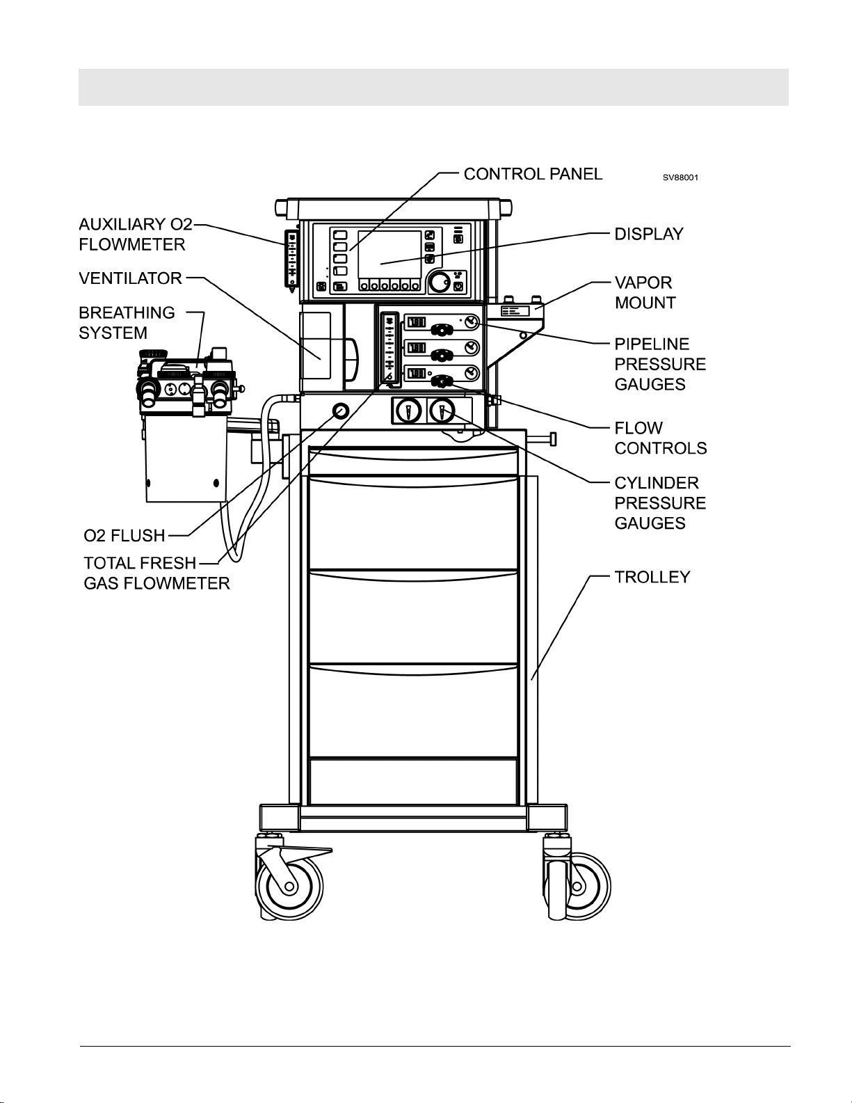
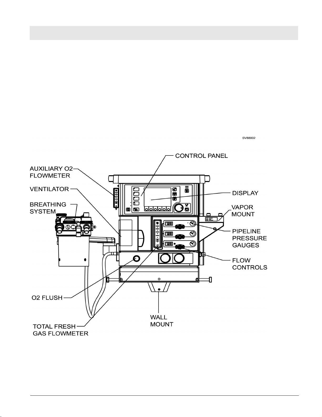
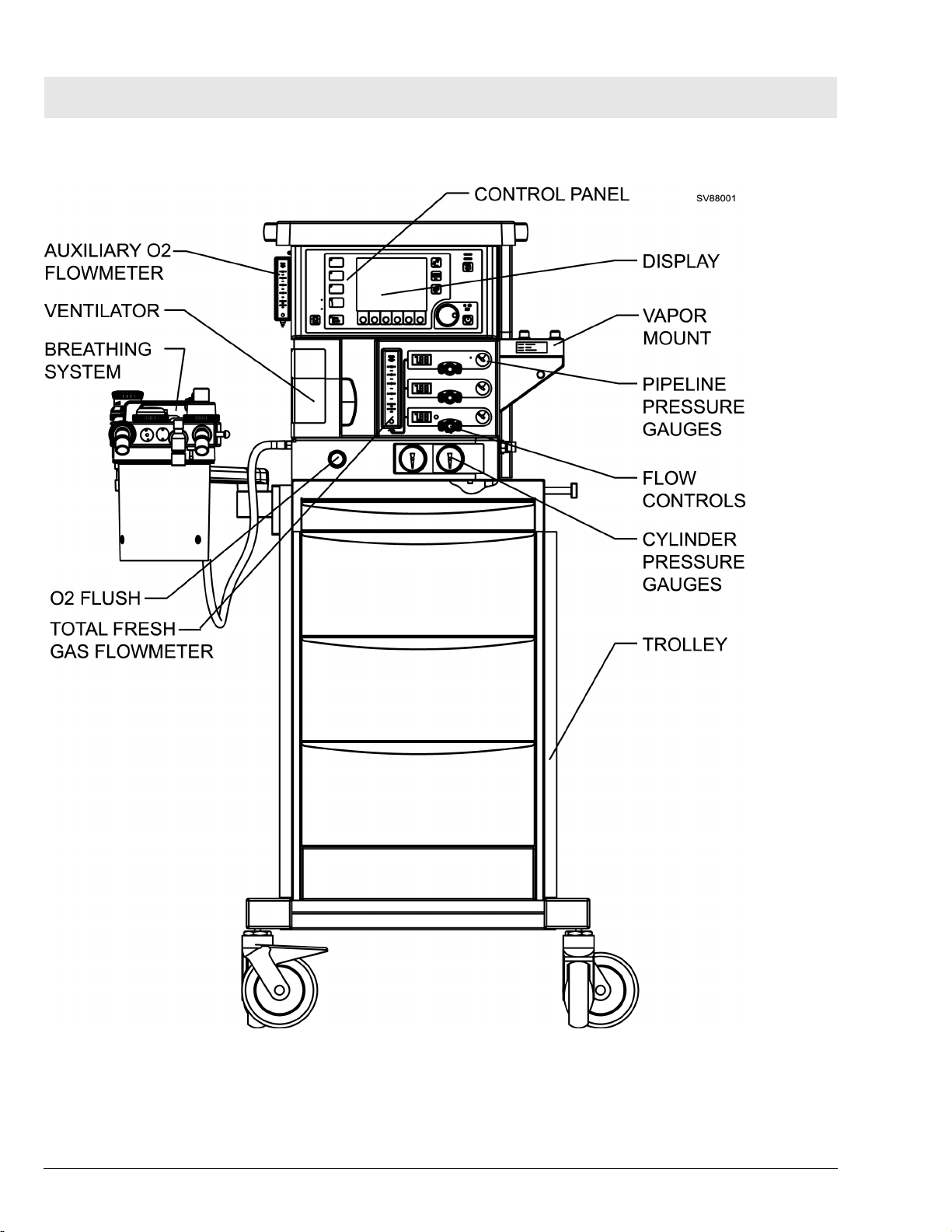
There are two possible mounting configurations for the Fabius Tiro, a wall
mounted unit and a trolley mounted unit. A general arrangement of both
mounting configurations of the Fabius Tiro anesthesia system are shown in
Figure 1 and Figure 2.
Figure 1 Fabius Tiro - Wall Mount Configuration
4
Dräger Medical AG & Co. KGaA 6020.002 Revision B Released
All rights reserved. Copyright reserved.
K6020002_GeneralUSA.fm 17.06.04
Page 11
RETURN TO THIS MANUAL'S TABLE OF CONTENTS
RETURN TO CD-ROM TABLE OF CONTENTS
General Fabius Tiro
Figure 2 Fabius Tiro - Trolley Mount Configuration
All rights reserved. Copyright reserved.
K6020002_GeneralUSA.fm 17.06.04
Dräger Medical AG & Co. KGaA 6020.002 Revision B Released
5
Page 12

RETURN TO THIS MANUAL'S TABLE OF CONTENTS
RETURN TO CD-ROM TABLE OF CONTENTS
Fabius Tiro General
4 Copyright Copyright© 2004 by Draeger Medical, Inc. All rights reserved. No part of this
publication may be reproduced, transmitted, transcribed, or stored in a
retrieval system in any form or by any means, electronic or mechanical,
including photocopying and recording, without written permission of Draeger
Medical, Inc.
5 Trademark Notices Datagrip, DrägerService, ORM, Quality Service For Life, Respitone, Narko-
med, Vigilance Audit, Vitalert, Vitalink, Narkomed GS, Fabius, Fabius Tiro,
and Fabius GS are registered trademarks of Draeger Medical, Inc. All other
products or name brands are trademarks of their respective owners.
6Disclaimer The content of this manual is furnished for informational use only and is sub-
ject to change without notice. Draeger Medical, Inc. assumes no responsibility or liability for any errors or inaccuracies that may appear in this manual.
6
All rights reserved. Copyright reserved.
K6020002_GeneralUSA.fm 17.06.04
Dräger Medical AG & Co. KGaA 6020.002 Revision B Released
Page 13

RETURN TO THIS MANUAL'S TABLE OF CONTENTS
Function Description
RETURN TO CD-ROM TABLE OF CONTENTS
7
Page 14

RETURN TO THIS MANUAL'S TABLE OF CONTENTS
RETURN TO CD-ROM TABLE OF CONTENTS
8
Page 15
RETURN TO THIS MANUAL'S TABLE OF CONTENTS
RETURN TO CD-ROM TABLE OF CONTENTS
Function Description Fabius Tiro
1 General Information
about the Fabius
Tiro
The Fabius Tiro comprises the following assemblies:
– Bezel assembly: Display and Control Panel
– Flowmeter assembly
– Gas Box: Gas Inlet Assembly and related items
– Breathing system
– Pneumatic Assembly
– Ventilator
– Anesthetic Vaporizer(s)
– Trolley Mount and Wall Mount
Figure 1 Front View of Fabius Tiro Anesthesia System - Wall Mount Configuration
All rights reserved. Copyright reserved.
F6020002_Function_Description_USA.fm 17.06.04
Dräger Medical AG & Co. KGaA 6020.002 Revision B Released
9
Page 16
RETURN TO THIS MANUAL'S TABLE OF CONTENTS
RETURN TO CD-ROM TABLE OF CONTENTS
Fabius Tiro Function Description
Figure 2 Front View of Fabius Tiro Anesthesia System - Trolley Mount Configuration
10
Dräger Medical AG & Co. KGaA 6020.002 Revision B Released
All rights reserved. Copyright reserved.
F6020002_Function_Description_USA.fm 17.06.04
Page 17
RETURN TO THIS MANUAL'S TABLE OF CONTENTS
RETURN TO CD-ROM TABLE OF CONTENTS
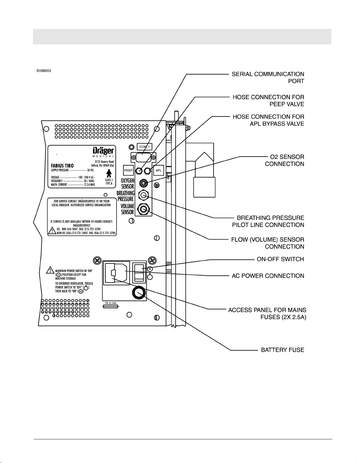
Function Description Fabius Tiro
Figure 3 Back View - Interface Panel and Power Entry
All rights reserved. Copyright reserved.
F6020002_Function_Description_USA.fm 17.06.04
Dräger Medical AG & Co. KGaA 6020.002 Revision B Released
11
Page 18
RETURN TO THIS MANUAL'S TABLE OF CONTENTS
RETURN TO CD-ROM TABLE OF CONTENTS
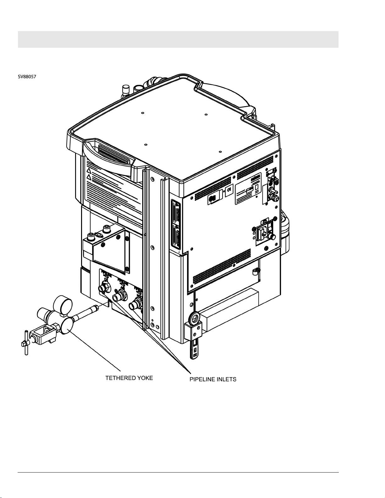
Fabius Tiro Function Description
Figure 4 Side View - Gas Pipeline Inlets and Tethered Yoke - Wall Mount Configuration
12
Dräger Medical AG & Co. KGaA 6020.002 Revision B Released
All rights reserved. Copyright reserved.
F6020002_Function_Description_USA.fm 17.06.04
Page 19
RETURN TO THIS MANUAL'S TABLE OF CONTENTS
RETURN TO CD-ROM TABLE OF CONTENTS
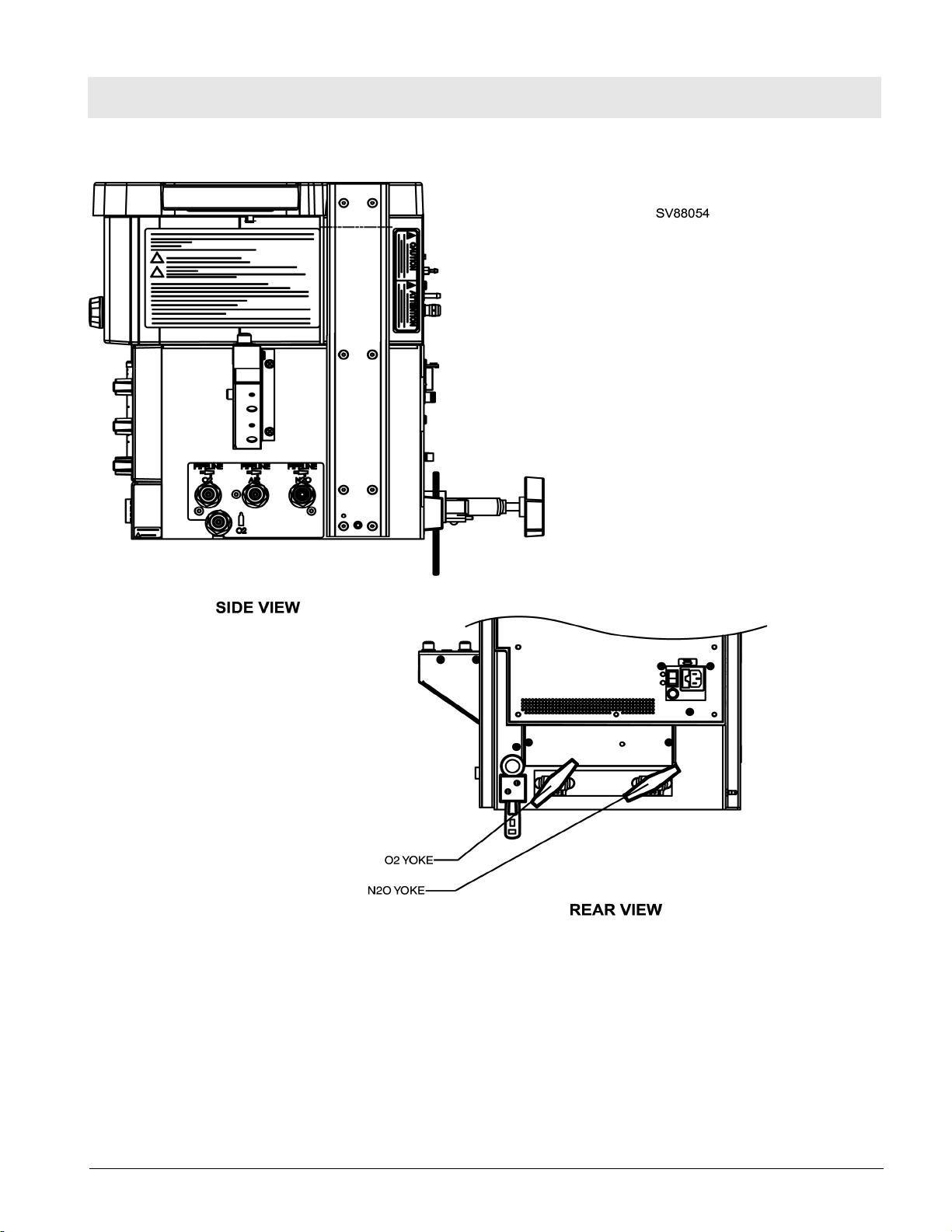
Function Description Fabius Tiro
Figure 5 Back/Side View - Gas Pipeline and Cylinder Hose Connections - Trolley Mount Configuration
All rights reserved. Copyright reserved.
F6020002_Function_Description_USA.fm 17.06.04
Dräger Medical AG & Co. KGaA 6020.002 Revision B Released
13
Page 20
RETURN TO THIS MANUAL'S TABLE OF CONTENTS
RETURN TO CD-ROM TABLE OF CONTENTS
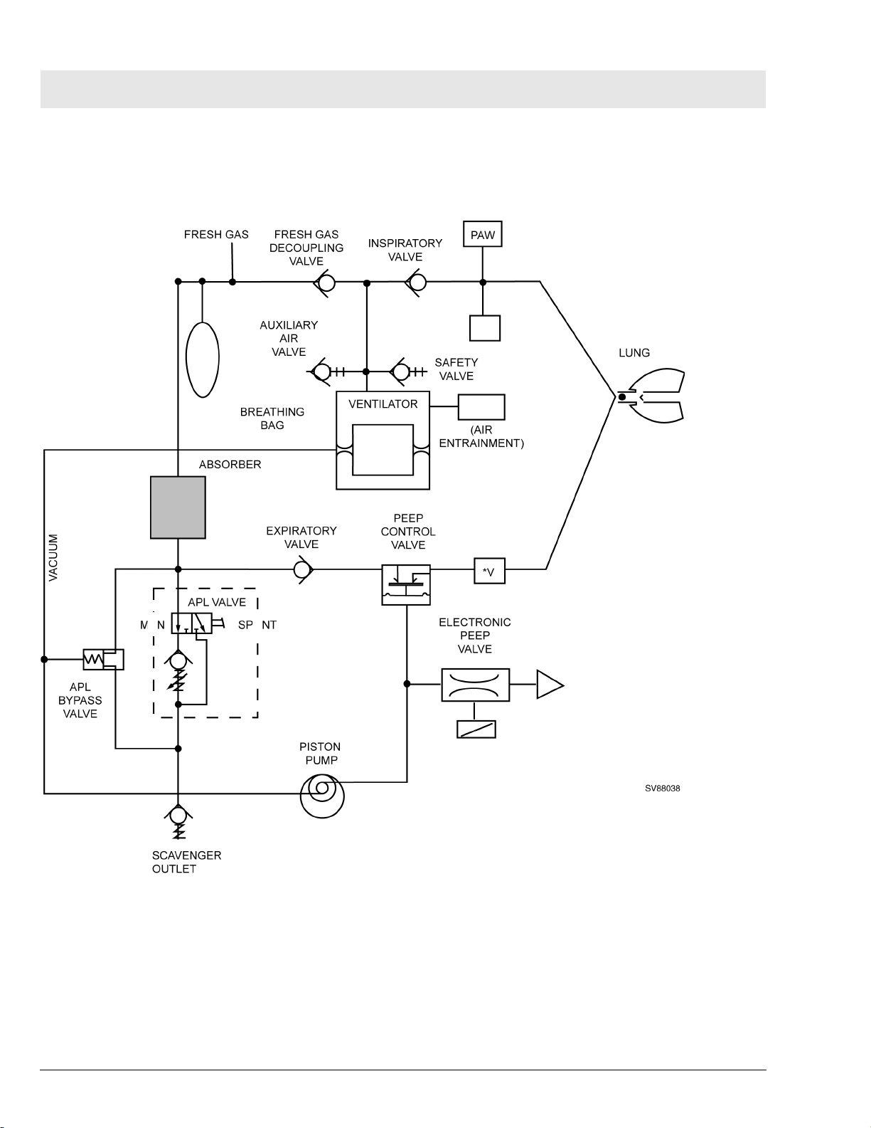
Fabius Tiro Function Description
2 Fabius Tiro Function
Diagram
Figure 6 Functional Diagram of Fabius Tiro - Typical for Breathing System P/N 4116398 or 4117529
14
Dräger Medical AG & Co. KGaA 6020.002 Revision B Released
All rights reserved. Copyright reserved.
F6020002_Function_Description_USA.fm 17.06.04
Page 21
RETURN TO THIS MANUAL'S TABLE OF CONTENTS
RETURN TO CD-ROM TABLE OF CONTENTS
Function Description Fabius Tiro
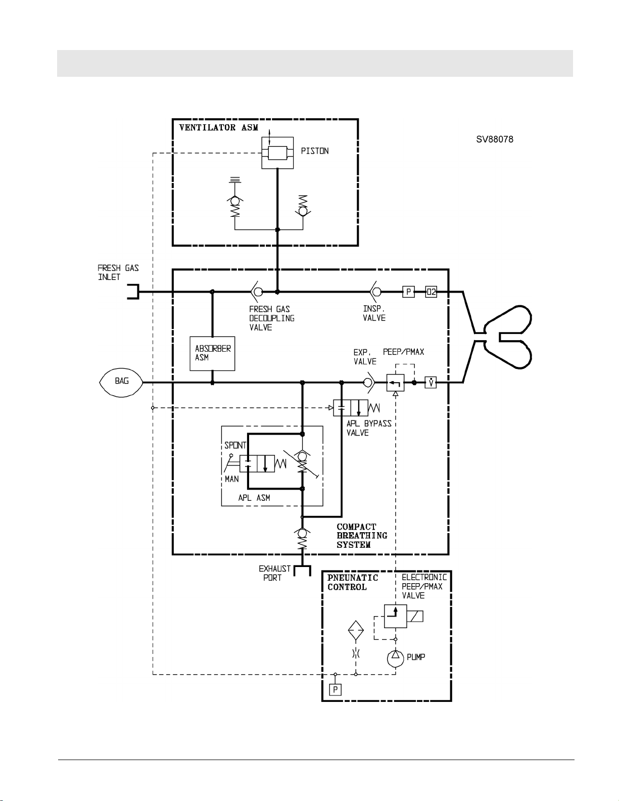
Figure 7 Function Diagram of Fabius Tiro - Typical for Breathing System P/N 4118378 or 4118379
All rights reserved. Copyright reserved.
F6020002_Function_Description_USA.fm 17.06.04
Dräger Medical AG & Co. KGaA 6020.002 Revision B Released
15
Page 22
RETURN TO THIS MANUAL'S TABLE OF CONTENTS
RETURN TO CD-ROM TABLE OF CONTENTS
Fabius Tiro Function Description
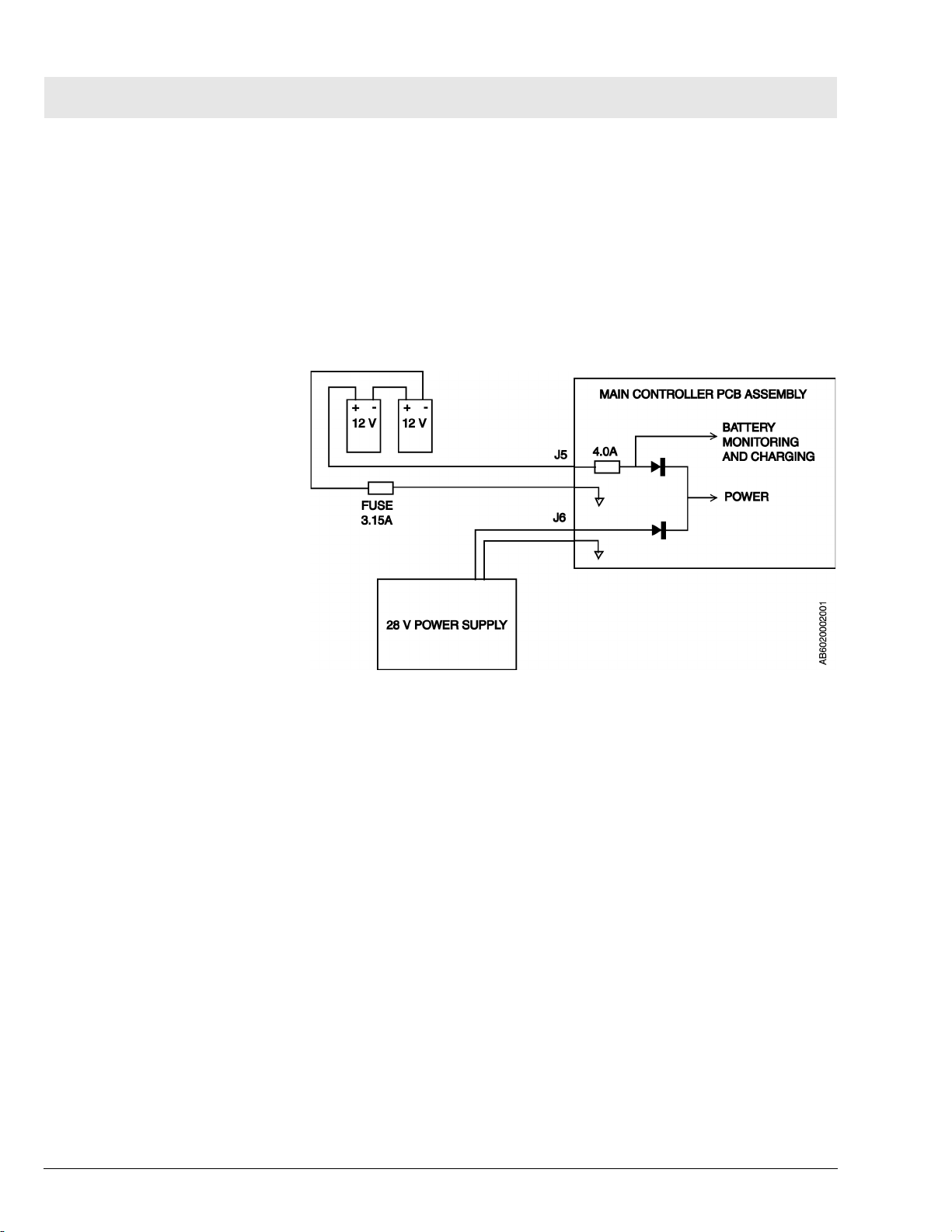
3 Battery Backup Fabius Tiro backup power is provided by two series-connected 12 V
rechargeable batteries. These batteries remain on charge as long as the
machine is plugged into an active AC outlet. Should power to the main controller PCB assembly fail while the machine is in operation, the batteries will
allow the machine to continue operating for a minimum of 45 minutes, provided the batteries are fully charged.
The batteries are located within the controller housing and are accessible by
opening the ventilator compartment. The 3.15A battery fuse is located on the
power entry panel at the back of the machine.
Figure 8 Battery Backup Arrangement
All rights reserved. Copyright reserved.
F6020002_Function_Description_USA.fm 17.06.04
16
Dräger Medical AG & Co. KGaA 6020.002 Revision B Released
Page 23

RETURN TO THIS MANUAL'S TABLE OF CONTENTS
RETURN TO CD-ROM TABLE OF CONTENTS
Function Description Fabius Tiro
4 Fabius Tiro Piping
Diagram
All rights reserved. Copyright reserved.
F6020002_Function_Description_USA.fm 17.06.04
Dräger Medical AG & Co. KGaA 6020.002 Revision B Released
17
Page 24
RETURN TO THIS MANUAL'S TABLE OF CONTENTS
RETURN TO CD-ROM TABLE OF CONTENTS
Fabius Tiro Function Description
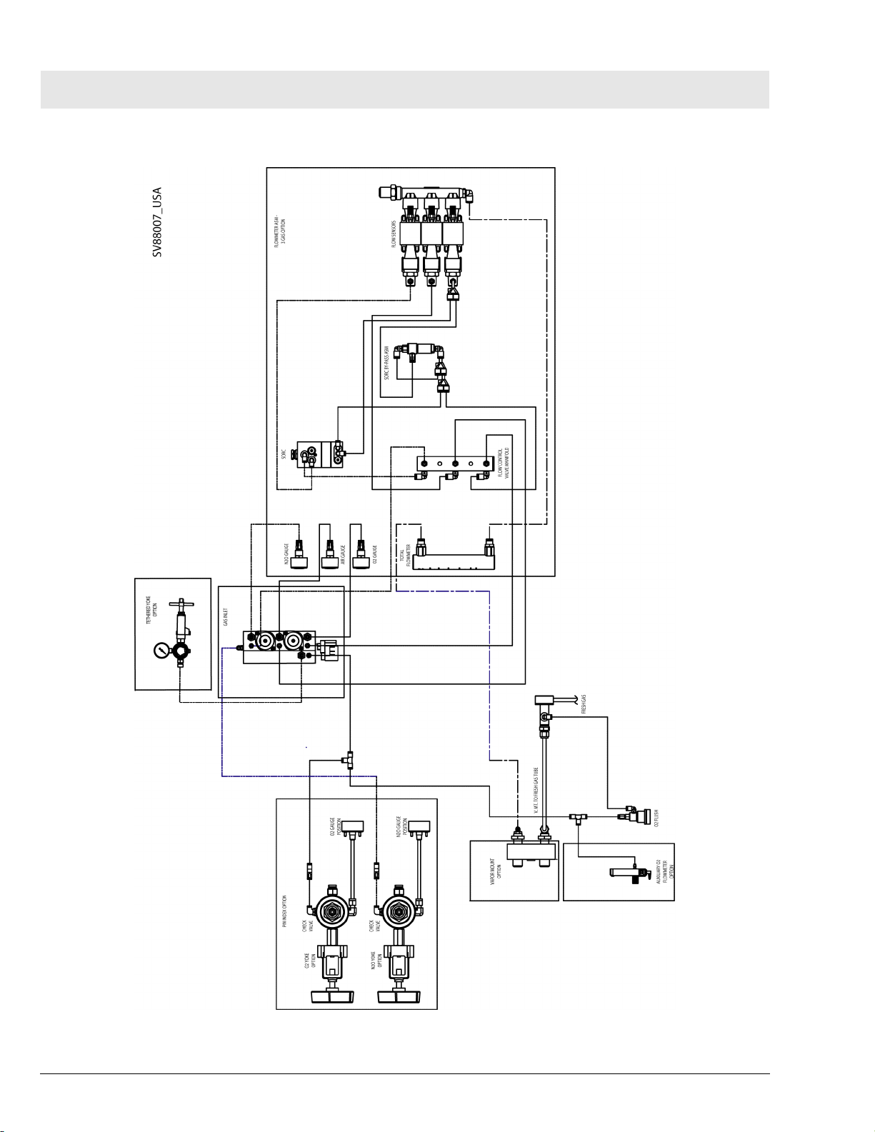
Figure 9 Fabius Tiro 3-Gas Piping Diagram
18
Dräger Medical AG & Co. KGaA 6020.002 Revision B Released
All rights reserved. Copyright reserved.
F6020002_Function_Description_USA.fm 17.06.04
Page 25
RETURN TO THIS MANUAL'S TABLE OF CONTENTS
RETURN TO CD-ROM TABLE OF CONTENTS
Function Description Fabius Tiro
5 Function Descrip-
tion of Gas Box
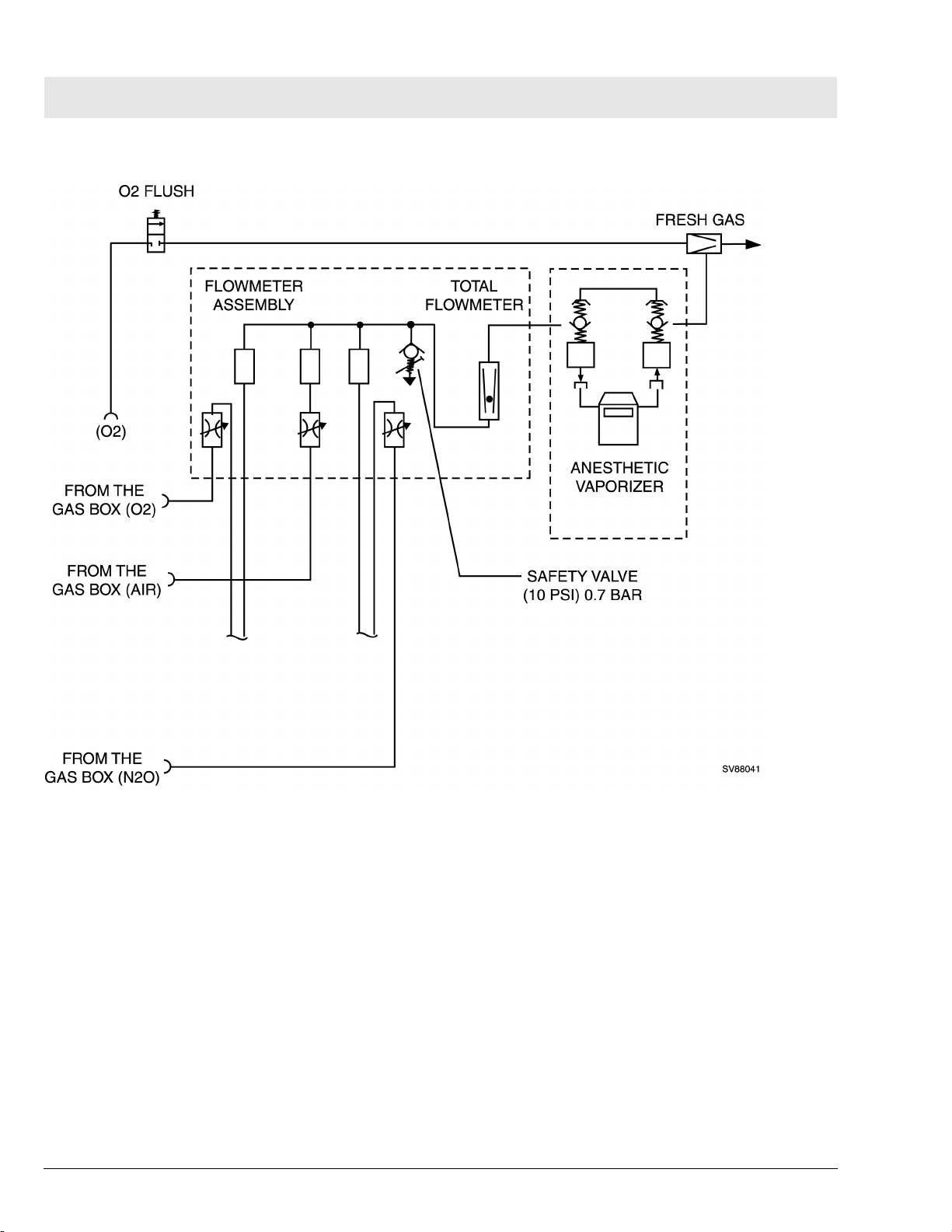
The supply gases flow through the filters and non-return valves in the gas
inlet assembly. Pipeline supply pressures are indicated on gauges located on
the flowmeter assembly. Cylinder pressure gauges are located on the base
machine assembly. The pressures of O2 and N2O delivered to the flowmeter
assembly are set by regulators on the gas inlet assembly.
Should the O2 supply fail or its pressure decrease below a certain limit, the
O2 supply pressure alarm switch signals an alarm.
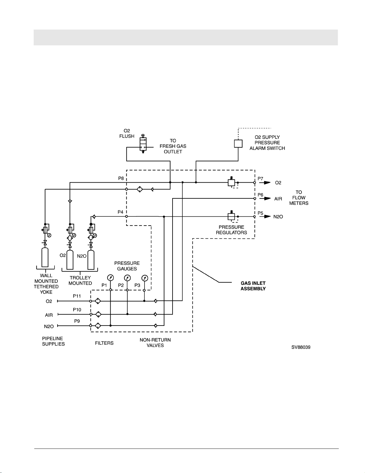
Figure 10 Gas Box Functional Diagram (Part 1 of 2)
If the O2 flush button is pressed, oxygen is delivered to the fresh gas outlet.
The fresh-gas ejector prevents the fresh gas from flowing back into the anesthetic vaporizer. This avoids an increase in the anesthetic gas concentration.
All rights reserved. Copyright reserved.
F6020002_Function_Description_USA.fm 17.06.04
Dräger Medical AG & Co. KGaA 6020.002 Revision B Released
19
Page 26
RETURN TO THIS MANUAL'S TABLE OF CONTENTS
RETURN TO CD-ROM TABLE OF CONTENTS
Fabius Tiro Function Description
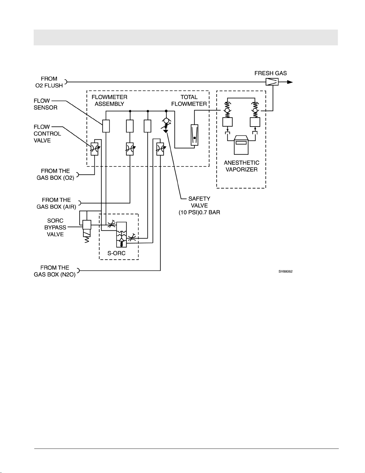
Figure 11 Gas Box Functional Diagram (Part 2 of 2)
6 SORC (Sensitive
Oxygen Ratio Controller)
20
Dräger Medical AG & Co. KGaA 6020.002 Revision B Released
The SORC is a control element that functions like an N2O shut-off device and
ensures a vital O2 concentration in the fresh gas. In the event of an O2 shortage, the SORC limits the N2O flow such that the O2 concentration in the
fresh gas does not decrease below 23 vol.%.
If the O2 flow control valve is closed or if the O2 flow is lower than or equal to
200 mL/min, the SORC interrupts the N2O flow.
N2O can be added when the O2 flow is approx. 300 mL/min. In this case, the
SORC also prevents O2 concentrations below 23 vol.%.
The SORC bypass allows O2 to bypass the restrictor in the SORC when O2
flows above 10 L/min. are needed.
All rights reserved. Copyright reserved.
F6020002_Function_Description_USA.fm 17.06.04
Page 27
RETURN TO THIS MANUAL'S TABLE OF CONTENTS
RETURN TO CD-ROM TABLE OF CONTENTS
Function Description Fabius Tiro
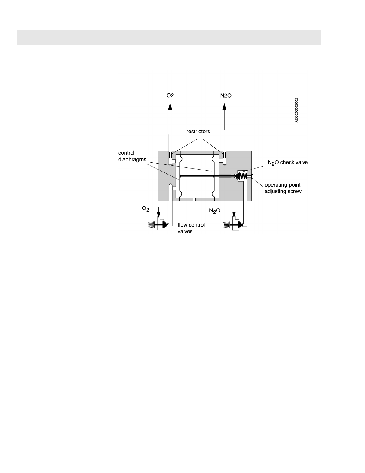
Figure 12 SORC Functional Diagram (Part 1 of 2)
The flow control valves are used to adjust the O2 and N2O flows.
Restrictors located at the outlets of the SORC generate back-pressures.
These back-pressures exert a force on the control diaphragms of the SORC.
The O2 back-pressure opens the SORC. The N2O back-pressure closes the
SORC. The pressure ratio at the control diaphragm affects the N2O flow.
The restrictors and the spring tension are dimensioned such that a minimum
concentration of 23 vol.% O2 is always ensured. The maximum O2 flow is
approx. 12 L/min.
All rights reserved. Copyright reserved.
F6020002_Function_Description_USA.fm 17.06.04
Dräger Medical AG & Co. KGaA 6020.002 Revision B Released
21
Page 28
RETURN TO THIS MANUAL'S TABLE OF CONTENTS
RETURN TO CD-ROM TABLE OF CONTENTS
Fabius Tiro Function Description
7 Compact Breathing
System, Cosy II
Figure 13SORC Functional Diagram (Part 2 of 2)
The Cosy II compact breathing system allows various modes of patient ventilation: manual and spontaneous breathing, volume controlled, and pressure
controlled.
In the "MAN" position, the compact breathing system is closed to atmosphere. This position is used for manual ventilation of the patient. The APL
valve opening pressure can be adjusted from 5 to 70 cmH2O.
In the "SPONT" position the APL valve is open to atmosphere. This position
is used for spontaneous patient breathing.
The pressure limit (Pmax) can also be adjusted (through front panel interface)
during volume control from 15 cmH2O to 70 cmH2O using the control box
and the PEEP/Pmax valve.
All rights reserved. Copyright reserved.
F6020002_Function_Description_USA.fm 17.06.04
22
Dräger Medical AG & Co. KGaA 6020.002 Revision B Released
Page 29
RETURN TO THIS MANUAL'S TABLE OF CONTENTS
RETURN TO CD-ROM TABLE OF CONTENTS
Function Description Fabius Tiro
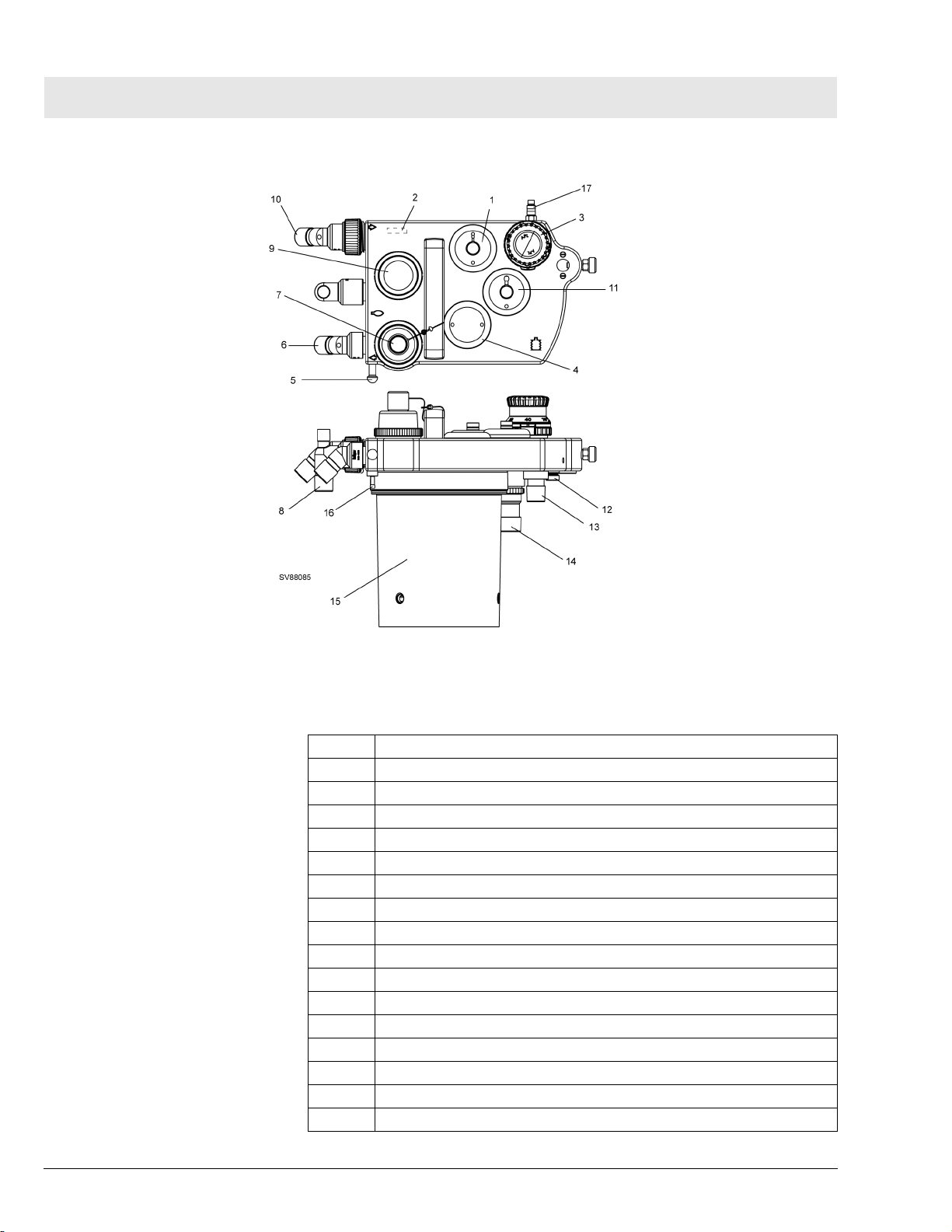
Figure 14 Compact Breathing System, Cosy II - Typical for P/N 4116398 or 4117529
Table 1 Key, Figure 14
1 PEEP/Pmax valve
2 Flow sensor (Spirolog)
3 MAN/SPONT-APL Valve
4 Fresh-gas decoupling valve
5 Breathing bag hook
6 Inspiratory port
7 Inspiratory valve and O2 sensor port
8 Breathing bag terminal and Y-piece plug
9 Expiratory valve
10 Expiratory port
11 APL Bypass valve
12 Fresh-gas port
13 Ventilator port
14 Anesthetic gas scavenging port
15 Absorber
16 Pressure sensor connector
17 Exhaust port, anesthetic monitor return (non-U.S. systems only)
All rights reserved. Copyright reserved.
F6020002_Function_Description_USA.fm 17.06.04
Dräger Medical AG & Co. KGaA 6020.002 Revision B Released
23
Page 30
RETURN TO THIS MANUAL'S TABLE OF CONTENTS
RETURN TO CD-ROM TABLE OF CONTENTS
Fabius Tiro Function Description
Figure 15 Compact Breathing System, Cosy II - Typical for P/N 4118378 or 4118379
Table 2 Key, Figure 15
1 PEEP/Pmax valve
2 Flow sensor (Spirolog)
3 MAN/SPONT-APL Valve
4 Fresh-gas decoupling valve
5 Breathing bag hook
6 Inspiratory port
7 Inspiratory valve and O2 sensor port
8 Breathing bag terminal and Y-piece plug
9 Expiratory valve
10 Expiratory port
11 APL Bypass valve
12 Fresh-gas port
13 Ventilator port
14 Anesthetic gas scavenging port
15 Absorber
16 Pressure sensor connector
17 Exhaust port, anesthetic monitor return (non-U.S. systems only)
All rights reserved. Copyright reserved.
F6020002_Function_Description_USA.fm 17.06.04
24
Dräger Medical AG & Co. KGaA 6020.002 Revision B Released
Page 31

RETURN TO THIS MANUAL'S TABLE OF CONTENTS
RETURN TO CD-ROM TABLE OF CONTENTS
Function Description Fabius Tiro
7.1 Manual Ventilation Manual Ventilation: General
During manual ventilation, the APL valve is set to the "MAN" position. The
patient system safety valve is activated. The piston of the ventilator is in the
upper end position in order to reduce the volume of the ventilator.
Manual Ventilation: Inspiration
During inspiration, expiratory valve remains closed. When the clinician compresses the breathing bag the gas mixture (expiratory gas and fresh gas)
flows through the fresh-gas decoupling valve, the inspiratory valve, the O2
sensor, the inspiratory hose, and the Y-piece into the patient’s lung. The pressure sensor measures the airway pressure. The APL valve limits the ventilation pressure. Any excess amount of the gas mixture flows through the APL
valve and the non-return valve to the anesthetic gas scavenging system.
Figure 16 Manual Ventilation (Inspiration) - Typical for Breathing System P/N 4116398 or 4117529
All rights reserved. Copyright reserved.
F6020002_Function_Description_USA.fm 17.06.04
Dräger Medical AG & Co. KGaA 6020.002 Revision B Released
25
Page 32

RETURN TO THIS MANUAL'S TABLE OF CONTENTS
RETURN TO CD-ROM TABLE OF CONTENTS
Fabius Tiro Function Description
Figure 17 Manual Ventilation (Inspiration) - Typical for Breathing System P/N 4118378 or 4118379
Manual Ventilation: Expiration - Typical for Breathing System P/N 4116398 or
4117529
During expiration, the inspiratory valve remains closed and thus prevents the
expiratory gas from flowing back into the inspiratory branch.
After releasing the breathing bag, the expiratory gas from the lung flows
through the expiratory hose, the flow sensor, the PEEP/Pmax valve, the expiratory valve, and through the absorber into the breathing bag. At the same
time, new fresh gas flows into the breathing bag.
26
Dräger Medical AG & Co. KGaA 6020.002 Revision B Released
All rights reserved. Copyright reserved.
F6020002_Function_Description_USA.fm 17.06.04
Page 33

RETURN TO THIS MANUAL'S TABLE OF CONTENTS
RETURN TO CD-ROM TABLE OF CONTENTS
Function Description Fabius Tiro
Figure 18 Manual Ventilation (Expiration) - Typical for Breathing System P/N 4116398 or 4117529
Manual Ventilation: Expiration - Typical for Breathing System P/N 4118378 or
4118379
During expiration, the inspiratory valve remains closed and thus prevents the
expiratory gas from flowing back into the inspiratory branch.
After releasing the breathing bag, the expiratory gas from the lung flows
through the expiratory hose, the flow sensor, the PEEP Pmax valve, the expiratory valve, onto the breathing bag and through the absorber. At the same
time, new fresh gas flows into the breathing bag.
All rights reserved. Copyright reserved.
F6020002_Function_Description_USA.fm 17.06.04
Dräger Medical AG & Co. KGaA 6020.002 Revision B Released
27
Page 34

RETURN TO THIS MANUAL'S TABLE OF CONTENTS
RETURN TO CD-ROM TABLE OF CONTENTS
Fabius Tiro Function Description
Figure 19 Manual Ventilation (Expiration) - Typical for Breathing System P/N 4118378 or 4118379
7.2 Spontaneous
Spontaneous Breathing: General
Breathing
A prerequisite for spontaneous breathing is that the patient is supplied with a
sufficient amount of fresh gas. The APL valve selector must be set to the
"SPONT" position. No pressure builds up in the compact breathing system.
Spontaneous Breathing: Inspiration
During inspiration, the expiratory valve remains closed thus preventing
rebreathing of expiratory gas containing CO2.
28
Dräger Medical AG & Co. KGaA 6020.002 Revision B Released
All rights reserved. Copyright reserved.
F6020002_Function_Description_USA.fm 17.06.04
Page 35

RETURN TO THIS MANUAL'S TABLE OF CONTENTS
RETURN TO CD-ROM TABLE OF CONTENTS
Function Description Fabius Tiro
The patient inhales the gas mixture (expiratory gas and fresh gas) from the
breathing bag. The gas mixture flows through the fresh-gas decoupling valve,
the inspiratory valve, the O2 sensor, the inspiratory hose, and through the Ypiece into the lung. The pressure sensor measures the airway pressure.
Figure 20 Spontaneous Breathing (Inspiration) - Typical for Breathing System P/N 4116398 or 4117529
All rights reserved. Copyright reserved.
F6020002_Function_Description_USA.fm 17.06.04
Dräger Medical AG & Co. KGaA 6020.002 Revision B Released
29
Page 36

RETURN TO THIS MANUAL'S TABLE OF CONTENTS
RETURN TO CD-ROM TABLE OF CONTENTS
Fabius Tiro Function Description
Figure 21 Spontaneous Breathing (Inspiration) - Typical for Breathing System P/N 4118378 or 4118379
Spontaneous Breathing: Expiration - Typical for Breathing System P/N
4116398 or 4117529
During expiration, the inspiratory valve remains closed thus preventing the
expiratory gas from flowing back into the inspiratory branch.
The APL valve is open, regardless of its pressure setting.
The expiratory gas flows from the lung through the expiratory hose, the flow
sensor, the PEEP control valve, the expiratory valve, and through the
absorber into the breathing bag. At the same time, new fresh gas flows into
the breathing bag.
30
Dräger Medical AG & Co. KGaA 6020.002 Revision B Released
All rights reserved. Copyright reserved.
F6020002_Function_Description_USA.fm 17.06.04
Page 37

RETURN TO THIS MANUAL'S TABLE OF CONTENTS
RETURN TO CD-ROM TABLE OF CONTENTS
Function Description Fabius Tiro
When the breathing bag is full, any excess gas mixture flows through the
non-return valve into the anesthetic gas scavenging system.
Figure 22 Spontaneous Breathing (Expiration) - Typical for Breathing System P/N 4116398 or 4117529
The CO2 is scrubbed from the expiratory gas by the soda lime contained in
the absorber. The fresh gas replaces the anesthetic and oxygen taken up by
the patient.
Spontaneous Breathing: Expiration - Typical for Breathing System P/N
4118378 or 4118379
During expiration, the inspiratory valve remains closed thus preventing the
expiratory gas from flowing back into the inspiratory branch.
The APL valve is open, regardless of its pressure setting.
All rights reserved. Copyright reserved.
F6020002_Function_Description_USA.fm 17.06.04
Dräger Medical AG & Co. KGaA 6020.002 Revision B Released
31
Page 38

RETURN TO THIS MANUAL'S TABLE OF CONTENTS
RETURN TO CD-ROM TABLE OF CONTENTS
Fabius Tiro Function Description
The expiratory gas flows from the lung through the expiratory hose, the flow
sensor, the PEEP control valve, the expiratory valve, the breathing bag, and
through the absorber. At the same time, new fresh gas flows into the breathing bag.
When the breathing bag is full, any excess gas mixture flows through the
non-return valve into the anesthetic gas scavenging system.
Figure 23 Spontaneous Breathing (Expiration) - Typical for Breathing System P/N 4118378 or 4118379
7.3 Volume/Pressure
Volume Control Mode: General
Mode Ventilation
A prerequisite for volume control is that the patient is supplied with a sufficient
amount of fresh gas.
The APL bypass valve opens in volume mode, allowing excess gas to be
vented to the scavenging system regardless of the MAN-SPONT valve setting.
32
Dräger Medical AG & Co. KGaA 6020.002 Revision B Released
All rights reserved. Copyright reserved.
F6020002_Function_Description_USA.fm 17.06.04
Page 39

RETURN TO THIS MANUAL'S TABLE OF CONTENTS
RETURN TO CD-ROM TABLE OF CONTENTS
Function Description Fabius Tiro
The safety valve of the patient system makes sure that no pressures greater
than 75 cmH2O build up in the system.
During ventilation, the pressure limit (Pmax) can be adjusted on the control
box.
Volume/Pressure Control Mode: Inspiration
During inspiration, the PEEP/Pmax valve remains closed. The control pressure present at the PEEP/Pmax valve varies with the set pressure limit
(Pmax).
The pressure generated by the ventilator’s piston closes the fresh-gas decoupling valve. The gas mixture (expiratory gas and fresh gas) flows through the
inspiratory valve, the O2 sensor, the inspiratory hose, and through the Ypiece into the lung. The pressure sensor measures the airway pressure. The
ventilation pressure cannot exceed the pressure limit (Pmax) set on the control box because the PEEP/Pmax valve opens. The fresh gas then fills the
breathing bag.
Any excess fresh gas flows through the open APL bypass valve, and through
the non-return valve into the anesthetic gas scavenging system.
All rights reserved. Copyright reserved.
F6020002_Function_Description_USA.fm 17.06.04
Dräger Medical AG & Co. KGaA 6020.002 Revision B Released
33
Page 40

RETURN TO THIS MANUAL'S TABLE OF CONTENTS
RETURN TO CD-ROM TABLE OF CONTENTS
Fabius Tiro Function Description
Figure 24 Volume Control Ventilation (Inspiration) - Typical for Breathing System P/N 4116398 or 4117529
34
Dräger Medical AG & Co. KGaA 6020.002 Revision B Released
All rights reserved. Copyright reserved.
F6020002_Function_Description_USA.fm 17.06.04
Page 41

RETURN TO THIS MANUAL'S TABLE OF CONTENTS
RETURN TO CD-ROM TABLE OF CONTENTS
Function Description Fabius Tiro
Figure 25 Volume Control Ventilation (Inspiration) - Typical for Breathing System P/N 4118378 or 4118379
Volume/Pressure Control Mode: Expiration
During expiration, the inspiratory valve remains closed thus preventing
rebreathing into the inspiratory branch.
The expiratory gas from the lung flows through the expiratory hose, the flow
sensor, the PEEP/Pmax valve, the expiratory valve, and through the absorber
back into the breathing bag mixing with fresh gas also flowing into the breathing bag.
The ventilator’s piston moves back drawing the gas mixture needed for the
next inspiration into the piston space.
All rights reserved. Copyright reserved.
F6020002_Function_Description_USA.fm 17.06.04
Dräger Medical AG & Co. KGaA 6020.002 Revision B Released
35
Page 42

RETURN TO THIS MANUAL'S TABLE OF CONTENTS
RETURN TO CD-ROM TABLE OF CONTENTS
Fabius Tiro Function Description
Any excess fresh-gas flows through the APL bypass valve, and through the
non-return valve into the anesthetic gas scavenging system.
Figure 26 Volume Control Ventilation (Expiration) - Typical for Breathing System P/N 4116398 or 4117529
36
Dräger Medical AG & Co. KGaA 6020.002 Revision B Released
All rights reserved. Copyright reserved.
F6020002_Function_Description_USA.fm 17.06.04
Page 43

RETURN TO THIS MANUAL'S TABLE OF CONTENTS
RETURN TO CD-ROM TABLE OF CONTENTS
Function Description Fabius Tiro
Figure 27 Volume Control Ventilation (Expiration) - Typical for Breathing System P/N 4118378 or 4118379
7.4 Cosy II Absorber The absorber canister is filled with fresh soda lime. The soda lime scrubs
CO2 from the respiratory expired gas.
Expired soda lime changes its color. The soda lime must be replaced when
two thirds of the soda lime in the absorber canister is discolored.
8 Ventilator The ventilator is located in a swing-out compartment at the left side of the
Fabius Tiro. A hose terminal is provided on the left side of the compartment
for connection to the breathing system. Fresh gas is delivered to the patient
by a piston that is driven by a motor and ball-screw arrangement. A sight window on the compartment allows the operator to verify movement of the piston.
All rights reserved. Copyright reserved.
F6020002_Function_Description_USA.fm 17.06.04
Dräger Medical AG & Co. KGaA 6020.002 Revision B Released
37
Page 44

RETURN TO THIS MANUAL'S TABLE OF CONTENTS
RETURN TO CD-ROM TABLE OF CONTENTS
Fabius Tiro Function Description
Two diaphragms (upper and lower) comprise a bag-type rolling seal that surrounds the piston. Vacuum from the pneumatic assembly (described in a later
paragraph) is provided between the outside of the seal and the cylinder, to
ensure proper operation of the seal during piston movement.
During inspiration the ventilator delivers fresh gas at a given volume, pressure and frequency. These parameters are set at the control panel. Refer to
the Operatorís Manual for details on ventilator settings, displays and controls.
During expiration, the bag-type rolling seal fills with expired gas from the
patient and with fresh gas stored in the breathing bag.
Power for the ventilator motor is distributed from the control PCB. A position
sensor on the ventilator signals the control PCB when the piston reaches its
lower limit. An incremental encoder on the motor shaft determines the number of revolutions and provides piston travel information to the control PCB.
Ventilator pressure is monitored by a transducer on the control PCB. Should
the negative pressure relief valve on the patient assembly open, a Fresh Gas
Low alarm is displayed if enabled via service mode.
The ventilator pressure transducer is the same type as the one used for measuring airway pressure. A hose connects the transducerís positive pressure
port to a hose barb located on the top cover of the ventilator. The purpose of
this transducer is to allow the software to sense when a condition exists that
would cause the ventilator negative pressure relief valve to open. The threshold used by the software for this condition is -8 mbar. In normal use the primary cause for this condition is an insufficient amount of reserve gas in the
breathing bag. The operator is alerted when this condition exists, with a
medium priority FRESH GAS LOW alarm. This alarm may be disabled via
service mode.
The ventilator assembly is illustrated on Figure 28.
All rights reserved. Copyright reserved.
F6020002_Function_Description_USA.fm 17.06.04
38
Dräger Medical AG & Co. KGaA 6020.002 Revision B Released
Page 45

RETURN TO THIS MANUAL'S TABLE OF CONTENTS
RETURN TO CD-ROM TABLE OF CONTENTS
Function Description Fabius Tiro
Figure 28 Ventilator (piston shown in down position)
The top of the ventilator assembly (patient system) contains two valves:
8.1 High Pressure Safety Valve
All rights reserved. Copyright reserved.
F6020002_Function_Description_USA.fm 17.06.04
Dräger Medical AG & Co. KGaA 6020.002 Revision B Released
If the pressure limit control fails, the patient system high pressure safety valve
limits the gas pressure. This valve is set to open at approximately 75 cmH2O.
39
Page 46

RETURN TO THIS MANUAL'S TABLE OF CONTENTS
RETURN TO CD-ROM TABLE OF CONTENTS
Fabius Tiro Function Description
Figure 29 Sectional View of the Safety Valve
8.2 Negative Pressure Relief Valve
Figure 30 Sectional View of the Negative Pressure Relief Valve
The negative pressure relief valve allows the patient to spontaneously
breathe ambient air should the medical gas supply and/or Fabius Tiro fail.
The opening pressure of this valve is -8 mbar.
9 Pneumatic System The pneumatic assembly provides pressure for the PEEP valve control, and
also provides vacuum for the ventilator bag-type rolling seals and the APL
bypass valve control.
All rights reserved. Copyright reserved.
F6020002_Function_Description_USA.fm 17.06.04
40
Dräger Medical AG & Co. KGaA 6020.002 Revision B Released
Page 47

RETURN TO THIS MANUAL'S TABLE OF CONTENTS
RETURN TO CD-ROM TABLE OF CONTENTS
Function Description Fabius Tiro
Figure 31 Pneumatic Control System Schematic
9.1 PEEP/Pmax Valve Control
9.2 APL Bypass Valve Control
All rights reserved. Copyright reserved.
F6020002_Function_Description_USA.fm 17.06.04
Dräger Medical AG & Co. KGaA 6020.002 Revision B Released
When the Fabius Tiro is operating in the automatic mode, the pump on the
pneumatic assembly is running, and the electronic PEEP valve receives a
signal from the main control PCB. The amount of current supplied to the coil
of the electronic PEEP valve is proportional to the PEEP value set by the
operator, and controls the position of the diaphragm within the electronic
PEEP valve. This then determines the control pressure applied to the proportional PEEP valve in the breathing system, which maintains the desired
amount of PEEP during patient expiration. The V1 reservoir smooths out
pressure variations caused by the pump. See Figure 29.
When the Fabius Tiro is operating in the automatic mode, the pneumatic
assembly provides a vacuum signal to hold open the APL bypass valve in the
breathing system. The V2 reservoir and filter provide noise damping, and the
variable restrictor is used to set the vacuum level in the range of -150 to -240
cmH2O.
41
Page 48

RETURN TO THIS MANUAL'S TABLE OF CONTENTS
RETURN TO CD-ROM TABLE OF CONTENTS
Fabius Tiro Function Description
When the machine is operating in the Manual mode, the pump on the pneumatic assembly (and the ventilator) is stopped, and the spring-loaded APL
bypass valve in the breathing system closes, directing exhaled gas through
the APL valve.
42
Dräger Medical AG & Co. KGaA 6020.002 Revision B Released
All rights reserved. Copyright reserved.
F6020002_Function_Description_USA.fm 17.06.04
Page 49

RETURN TO THIS MANUAL'S TABLE OF CONTENTS
RETURN TO CD-ROM TABLE OF CONTENTS
Function Description Fabius Tiro
10 Electronic Block
Diagram
Figure 32 Electronic Block Diagram
All rights reserved. Copyright reserved.
F6020002_Function_Description_USA.fm 17.06.04
Dräger Medical AG & Co. KGaA 6020.002 Revision B Released
43
Page 50

RETURN TO THIS MANUAL'S TABLE OF CONTENTS
RETURN TO CD-ROM TABLE OF CONTENTS
Fabius Tiro Function Description
11 Control PCB The control PCB provides the following functions in the Fabius Tiro:
11.1 Flowmeter Receives flow rate data from the N2O, Air, and O2 flow sensors and provides
fresh gas display information for these gases.
11.2 Patient Interface Receives information from the oxygen sensor and processes it for display.
Receives flow information from the Spirolog sensor and processes it for display.
Converts airway breathing pressure to an electrical signal and processes it
for display.
11.3 Ventilator Provides ventilator motor drive, receives ventilator piston position and move-
ment information. Provides ventilator pressure information.
11.4 Front Panel Func-
Provides power for the display panel and LED table lamp.
tions
Provides video signals to the display.
Receives information from the keypad and rotary encoder for making display
and operating selections, setting alarm limits, and service functions.
11.5 Pneumatic Assem-
Provides power to the pump on the pneumatic assembly.
bly Control
Provides control signal to the electronic PEEP valve on the pneumatic
assembly in response to operator setting.
Monitors pump vacuum to stabilize PEEP control.
11.6 Serial Port Interface Provides isolated port for connecting external monitors and downloading soft-
ware.
11.7 Battery Provides charging current for battery and monitors state of battery charge.
All rights reserved. Copyright reserved.
F6020002_Function_Description_USA.fm 17.06.04
44
Dräger Medical AG & Co. KGaA 6020.002 Revision B Released
Page 51

RETURN TO THIS MANUAL'S TABLE OF CONTENTS
RETURN TO CD-ROM TABLE OF CONTENTS
Function Description Fabius Tiro
Figure 33 Controller Functional Block Diagram
12 Control Panel
Assembly
All rights reserved. Copyright reserved.
F6020002_Function_Description_USA.fm 17.06.04
Dräger Medical AG & Co. KGaA 6020.002 Revision B Released
The control panel assembly consists of a 320 x 240 pixel graphical display, a
table lamp with six LEDs, a membrane keypad, rotary encoder and speaker.
45
Page 52

RETURN TO THIS MANUAL'S TABLE OF CONTENTS
RETURN TO CD-ROM TABLE OF CONTENTS
Fabius Tiro Function Description
Data and power for the display comes from the main controller PCB via a 20conductor ribbon cable. The keypad interface is connected to the main controller PCB by a 30-conductor ribbon cable. A block diagram of the control
panel assembly is shown in Figure 34.
Figure 34 Control Panel Block Diagram
An illustration of the control panel is shown in Figure 35.
All rights reserved. Copyright reserved.
F6020002_Function_Description_USA.fm 17.06.04
Figure 35 Fabius Tiro Control Panel (Main Service Screen Illustrated)
46
Dräger Medical AG & Co. KGaA 6020.002 Revision B Released
Page 53

RETURN TO THIS MANUAL'S TABLE OF CONTENTS
RETURN TO CD-ROM TABLE OF CONTENTS
Function Description Fabius Tiro
Descriptions of the numbered items in Figure 35 are given in the Tabl e 3.
Table 3 Fabius Tiro Control Panel Key for Figure 35
ITEM FUNCTION
1 Selects volume controlled ventilation mode. Refer to Operator’s Manual
2 Select pressure controlled ventilator mode. Refer to Operator’s Manual
3 Reserved for future use
4 Reserved for future use
5 Controls table lamp: Off/On
6 Places ventilator in Man Spont mode. Refer to Operator’s Manual
7 Soft Keys: active the corresponding function that appears on screen above the key
8 For setting alarm limits. Refer to Operator’s Manual
9 Setup Key: activates sub-screens for monitoring functions. Refer to Operator’s Manual
10 Home key: returns display to main screen shown before standby
11 Rotary control: moves the cursor on the screen; confirms selection when pressed
12 Alarm Status Indicators: Flashing Red: Warning; Flashing Yellow: Caution; Solid Yellow: Advi-
sory
13 Alarm Silence key: silences all active alarms for two minutes
14 Power ON indicator: lighted when machine is plugged into an active AC outlet
15 Returns unit to Standby mode
13 FiO2 Measurement The O2 sensor measures the fraction of inspired O2 (FiO2) in the respiratory
gas.
The O2 sensor contains an alkaline electrolyte, a lead anode, two gold cathodes, and a Teflon membrane. The spatial separation of the two gold cathodes allows a voltage comparison to be made as explained below.
The O2 sensor is an electrochemical cell that generates a voltage from the
ion current.
All rights reserved. Copyright reserved.
F6020002_Function_Description_USA.fm 17.06.04
Dräger Medical AG & Co. KGaA 6020.002 Revision B Released
47
Page 54

RETURN TO THIS MANUAL'S TABLE OF CONTENTS
RETURN TO CD-ROM TABLE OF CONTENTS
Fabius Tiro Function Description
Figure 36 O2 Sensor
14 Respiratory Flow
Measurement
The O2 to be measured diffuses through the Teflon membrane, reacts at the
gold cathodes (negative polarity) and forms lead oxide and water at the lead
anode (positive polarity). During this chemical process, a voltage is generated which is proportional to the O2 partial pressure.
The internal resistance of the cell is determined by the surface area of the
gold cathodes, the O2 diffusion velocity, the distance between the gold cathodes and the lead anode. This resistance is approximately 700 ohms.
The chemical process is temperature-sensitive. Therefore temperature-sensitive resistors are connected in parallel with the O2 sensor. These resistors
and the internal resistance of the O2 sensor correct the measuring voltage.
Because two cathodes used in the O2 sensor cell, two different voltages are
generated. These voltages are compared with each other. If their difference
exceeds a certain value, the machine prompts the operator to check the cell.
If the O2 sensor fails, the control box will indicate an error on the graphics
display.
The flow sensor functions according to the constant temperature hot-wire
anemometer principle. Respiratory gas flows past a thin platinum wire. This
platinum wire (A) is located in a measuring tube and is electrically heated.
The platinum wire is held at a constant temperature. Gas flow removes heat
from the hot wire. The higher the gas flow rate, the greater the heat removal.
The amount of electrical current needed to maintain a constant platinum wire
temperature is thus proportional to the gas flow rate.
All rights reserved. Copyright reserved.
F6020002_Function_Description_USA.fm 17.06.04
48
Dräger Medical AG & Co. KGaA 6020.002 Revision B Released
Page 55

RETURN TO THIS MANUAL'S TABLE OF CONTENTS
RETURN TO CD-ROM TABLE OF CONTENTS
Function Description Fabius Tiro
A second platinum wire (B) in the measuring tube is used to compensate for
interferences from different gases present in the respiratory gas. The heat
removed from the second platinum wire is measured during inspiration when
the gas flow is zero.
The different gases present in the respiratory gas have a different thermal
conductivity. The amount of heat removed from the second platinum wire is
thus an indicator of respiratory gas composition.
Internal calibration tables for O2/N2O mixtures, Air and 100% O2 are used to
linearize the measured flow.
Figure 37 Respiratory Flow Sensor
15 Gas Flow Rate Mea-
surement
The gas flow sensors operate on the principle of specific heat for individual
gases. In each sensor, as the gas flows through a heated chamber the gas
molecules carry away a certain amount of heat relative to the specific heat
index for that gas.
A known amount of electrical current is required to maintain the temperature
in the heated chamber. The higher the gas flow rate, the more heat is
removed from the chamber and more current is required to maintain the temperature in the chamber. This current is then scaled and displayed as liters
per minute flow rate for each gas.
All rights reserved. Copyright reserved.
F6020002_Function_Description_USA.fm 17.06.04
Dräger Medical AG & Co. KGaA 6020.002 Revision B Released
49
Page 56

RETURN TO THIS MANUAL'S TABLE OF CONTENTS
RETURN TO CD-ROM TABLE OF CONTENTS
Fabius Tiro Function Description
Figure 38 Flow Sensor Details
Figure 39 Flow of Gases through Sensors
16 Vaporizer Refer to separate technical documentation of the anesthetic vaporizer.
50
Dräger Medical AG & Co. KGaA 6020.002 Revision B Released
All rights reserved. Copyright reserved.
F6020002_Function_Description_USA.fm 17.06.04
Page 57

RETURN TO THIS MANUAL'S TABLE OF CONTENTS
RETURN TO CD-ROM TABLE OF CONTENTS
ELECTROMAGNETIC TESTING AND
COMPLIANCE
51
Page 58

RETURN TO THIS MANUAL'S TABLE OF CONTENTS
RETURN TO CD-ROM TABLE OF CONTENTS
52
Page 59

RETURN TO THIS MANUAL'S TABLE OF CONTENTS
RETURN TO CD-ROM TABLE OF CONTENTS
Fabius Tiro Electromagnetic Testing and Compliance
1 Electromagnetic
Testing and Compliance
The following CAUTIONS and WARNINGS are applicable to the Fabius Tiro
Anesthesia Machine:
CAUTION
Do not use Fabius Tiro in the environment of NMR tomography equipment. Malfunctions may result, thereby endangering the patient.
CAUTION
The use of portable and mobile radio frequency communications
equipment can affect medical electrical equipment. Do not use mobile
phones within a distance of 10 meters from the machine. Mobile
phones can cause malfunctions in electrical medical equipment,
thereby endangering the patient and the operator.
WARNING
No third-party components shall be attached to the anesthesia
machine, ventilator, or breathing system (except for certain approved
exceptions). For more information, contact your local Authorized Service Organization or DrägerService at:
DrägerService
Draeger Medical, Inc.
3122 Commerce Drive
Telford, PA 18969
Tel:(215) 721-5402
(800) 543-5047
Fax:(215) 721-5784
CAUTION
Although the Fabius Tiro is designed to minimize the effects of ambient radio-frequency interference, machine functions may be
adversely affected by the operation of electrosurgical equipment or
short wave or microwave diathermy equipment in the vicinity.
CAUTION
Communications with external equipment may be temporarily
affected by electromagnetic interference due to the use of electrosurgical equipment.
Tables 1 through 4 contained in this section are provided for informational
purposes and general guidance, as required by IEC 60601-1-2:2001, Medical
Electrical Equipment, Part 1-2, General Requirements for Safety - Collateral
Standard: Electromagnetic Compatibility.
2 Guidance and manu-
facturer’s declaration-electromagnetic
All rights reserved. Copyright reserved.
L6020002_EMC.fm 17.06.04
Dräger Medical Systems, Inc. 6020.002 Revision B Released
emissions
The Fabius Tiro is intended for use in the electromagnetic environment specified below. The customer or the user of the Fabius Tiro should assure that it
is used in such an environment.
53
Page 60

RETURN TO THIS MANUAL'S TABLE OF CONTENTS
RETURN TO CD-ROM TABLE OF CONTENTS
Electromagnetic Testing and Compliance Fabius Tiro
Table 1 Electromagnetic Emissions
Emissions test Compliance level Recommendations
3 Guidance and manu-
facturer’s declaration-electromagnetic
immunity
RF emissions
CISPR 11
RF emissions
CISPR 11
Harmonic emissions
IEC 61000-3-2
Class A
Voltage fluctuations/flicker emissions
IEC 61000-3-3
The Fabius Tiro is intended for use in the electromagnetic environment specified below. The customer or the user of the Fabius Tiro should assure that it
is used in such an environment.
Table 2 Electromagnetic Immunity
Group 1 The Fabius Tiro uses RF energy
only for its internal function.
Therefore, its RF emissions are
very low and are not likely to
cause any interference in nearby
electronic equipment.
Class B The Fabius Tiro is suitable for
use in all establishments, except
Complies
Complies
NMR environments, including
domestic establishments and
those directly connected to the
public low-voltage power supply
network that supplies buildings
used for domestic purposes.
Immunity test IEC 60601 test
level
Electrostatic discharge (ESD)
IEC61000-4-2
Electrical fast
Transient/burst
IEC61000-4-4
Surge
IEC61000-4-5
+/-6 kV contact
+/-8 kV air
+/-2 kV for power
supply lines
+/-1 kV for
input/output lines
+/-1 kV differential mode
+/-2 kV common
mode
Compliance
level
Complies Floors should be
Complies Mains power quality
Complies Mains power quality
Recommendations
wood, concrete, or
ceramic tile. If floors
are covered with
synthetic material,
the relative humidity
should be at least
30%.
should be that of a
typical commercial or
hospital environment.
should be that of a
typical commercial or
hospital environment.
L6020002_EMC.fm 17.06.04
All rights reserved. Copyright reserved.
54
Dräger Medical Systems, Inc. 6020.002 Revision B Released
Page 61

RETURN TO THIS MANUAL'S TABLE OF CONTENTS
RETURN TO CD-ROM TABLE OF CONTENTS
Fabius Tiro Electromagnetic Testing and Compliance
Immunity test IEC 60601 test
level
Voltage dips,
short interruptions, and voltage variations on
power supply
input lines
IEC 61000-4-11
Power frequency
(50/60 Hz) magnetic field
IEC61000-4-8
<5% Ut
(>95% dip in Ut)
for 0.5 cycle
40% Ut
(60% dip in Ut)
for 5 cycles
70% Ut
(30% dip in Ut)
for 25 cycles
<5% VT
(>95% dip in Ut)
for 5 seconds
3 A/m Complies Power frequency
Compliance
level
Complies Mains power quality
Recommendations
should be that of a
typical commercial or
hospital environment. The Fabius
Tiro provides battery
back-up in the event
of a power failure.
magnetic fields
should be at levels
characteristic of a
typical location in a
typical commercial or
hospital environment.
NOTE
Ut is the a.c. mains voltage prior to application of the test level.
4 Guidance and manu-
facturer’s declaration-electromagnetic
The Fabius Tiro is intended for use in the electromagnetic environment specified below. The customer or the user of the Fabius Tiro should assure that it
is used in such an environment.
immunity
Table 3 Electromagnetic Immunity
Immunity
test
All rights reserved. Copyright reserved.
L6020002_EMC.fm 17.06.04
IEC 60601
test level
Compliance
level
Electromagnetic environ-
ment-guidance
Portable and mobile RF communications equipment
should be used no closer to
any part of the Fabius Tiro,
including cables, than the
recommended separation
distance calculated from the
equation applicable to the frequency of the transmitter.
Dräger Medical Systems, Inc. 6020.002 Revision B Released
55
Page 62

RETURN TO THIS MANUAL'S TABLE OF CONTENTS
RETURN TO CD-ROM TABLE OF CONTENTS
Electromagnetic Testing and Compliance Fabius Tiro
Immunity
test
Conducted
RF
IEC61000-46
Radiated RF
IEC61000-43
IEC 60601
test level
3 Vrms
150 kHz to
80 MHz outside ISM
bands (ref.
NOTE A)
10 Vrms
150 kHz to
80 MHz in
ISM bands
(Ref. NOTE
A)
10 V/m
80 MHz to
2.5 GHz
Compliance
level
[V1] V
Complies
[V2] V
Complies
[E1] V/m
Complies
Electromagnetic environ-
ment-guidance
Recommended separation
distance
d=[3.5/V1]vP
d=[12/V2]vP
d=[12/E1]vP 80 MHz to
800 MHz
d=[23/E1]vP 800 MHz to
2.5 GHz
where P is the maximum output power rating of the transmitter in watts (W) according
to the transmitter manufacturer and d is the recommended separation distance
in meters (m) (Ref. NOTE B).
Field strengths from fixed RF
transmitters, as determined
by an electromagnetic site
survey (ref. NOTE C), should
be less than the compliance
level in each frequency range
(Ref. NOTE D).
Interference may occur in the
vicinity of equipment marked
with the following symbol:
((e»)
NOTE
At 80 MHz and 800 MHz, the higher frequency range applies.
56
Dräger Medical Systems, Inc. 6020.002 Revision B Released
L6020002_EMC.fm 17.06.04
All rights reserved. Copyright reserved.
Page 63

RETURN TO THIS MANUAL'S TABLE OF CONTENTS
RETURN TO CD-ROM TABLE OF CONTENTS
Fabius Tiro Electromagnetic Testing and Compliance
NOTE
These guidelines may not apply in all situations. Electromagnetic propagation is affected by absorption and reflection from structures, objects, and
people.
NOTE A
The ISM (industrial, scientific, and medical) bands between 150 kHz and
80 MHz are 6.765 MHz to 6.795 MHz; 13.553 MHz to 13.567 MHz;
26.957 MHz to 27.283 MHz; and 40.66 MHz to 40.70 MHz.
NOTE B
The compliance levels in the ISM frequency bands between 150 kHz and
80 MHz and in the frequency range 80 MHz to 2.5 GHz are intended to
decrease the likelihood that mobile/portable communications equipment
could cause interference if it is inadvertently brought into patient areas. For
this reason, an additional factor of 10/3 is used in calculating the recommended separation distance for transmitters in these frequency ranges.
5 Recommended sep-
aration distances
between portable
and mobile RF communications equipment and the Fabius
Tiro
NOTE C
Field strengths from fixed transmitters, such as base stations for radio (cellular/cordless) telephones and land mobile radios, amateur radio, AM and
FM radio broadcast, and TV broadcast cannot be predicted theoretically
with accuracy. To assess the electromagnetic environment due to fixed RF
transmitters, an electromagnetic site survey should be considered. If the
measured field strength in the location in which the Fabius Tiro is used
exceeds the applicable RF compliance level above, the Fabius Tiro should
be observed to verify normal operation. If abnormal performance is
observed, additional measures may be necessary, such as re-orienting or
relocating the Fabius Tiro.
NOTE D
Over the frequency range 150 kHz to 80 MHz, field strengths should be
less than 1 V/m.
The Fabius Tiro is intended for use in an electromagnetic environment in
which radiated RF disturbances are controlled. The customer or the user of
the Fabius Tiro can help prevent electromagnetic interference by maintaining
a minimum distance between portable and mobile RF communications equipment (transmitters) and the Fabius Tiro as recommended below, according to
the maximum output power of the communications equipment.
Table 4 Distance Recommendations between RF Communications
All rights reserved. Copyright reserved.
L6020002_EMC.fm 17.06.04
Dräger Medical Systems, Inc. 6020.002 Revision B Released
57
Page 64

RETURN TO THIS MANUAL'S TABLE OF CONTENTS
RETURN TO CD-ROM TABLE OF CONTENTS
Electromagnetic Testing and Compliance Fabius Tiro
Equipment and the Fabius Tiro
Rated maximum output
Separation distance according to frequency of transmit-
ter (meters)
power of
transmitter
W(atts)
150 kHz to
80 MHz outside ISM
bands
150 kHz to
80 MHz in
ISM bands
d=[12/E1]vP
80 MHz to
800 MHz
d=[12/E1]vP
800 MHz to
2.5 GHz
d=[23/E1]vP
d=[3.5/V1] vP
0.01 0.116 0.120 0.120 0.230
0.1 0.368 0.379 0.379 0.727
1 1.166 1.200 1.200 2.300
10 3.689 3.794 3.794 7.273
100 11.66 12.000 12.000 23.000
For transmitters rated at a maximum output power not listed above, the recommended separation distance d in meters (m) can be determined using the
equation applicable to the frequency of the transmitter, where P is the maximum output power rating of the transmitter in watts (W) according to the
transmitter manufacturer.
NOTE
At 80 MHz and 800 MHz, the separation distance for the higher frequency
range applies.
NOTE
The ISM (industrial, scientific, and medical) bands between 150 kHz and
80 MHz are 6.765 MHz to 6.795 MHz; 13.553 MHz to 13.567 MHz; 26.957
MHz to 27.283 MHz; and 40.66 MHz to 40.70 MHz.
NOTE
An additional factor of 10/3 is used in calculating the recommended separation distance for transmitters in the ISM frequency bands between 150
kHz and 80 MHz and in the frequency range 80 MHz to 2.5 GHz to
decrease the likelihood that mobile/portable communications equipment
could cause interference if it is inadvertently brought into patient areas.
L6020002_EMC.fm 17.06.04
All rights reserved. Copyright reserved.
58
Dräger Medical Systems, Inc. 6020.002 Revision B Released
Page 65

RETURN TO THIS MANUAL'S TABLE OF CONTENTS
RETURN TO CD-ROM TABLE OF CONTENTS
Fabius Tiro Electromagnetic Testing and Compliance
NOTE
These guidelines may not apply in all situations. Electromagnetic propagation is affected by absorption and reflection from structures, objects, and
people.
All rights reserved. Copyright reserved.
L6020002_EMC.fm 17.06.04
Dräger Medical Systems, Inc. 6020.002 Revision B Released
59
Page 66

RETURN TO THIS MANUAL'S TABLE OF CONTENTS
RETURN TO CD-ROM TABLE OF CONTENTS
Electromagnetic Testing and Compliance Fabius Tiro
60
Dräger Medical Systems, Inc. 6020.002 Revision B Released
L6020002_EMC.fm 17.06.04
All rights reserved. Copyright reserved.
Page 67

RETURN TO THIS MANUAL'S TABLE OF CONTENTS
RETURN TO CD-ROM TABLE OF CONTENTS
TROUBLESHOOTING GUIDE
61
Page 68

RETURN TO THIS MANUAL'S TABLE OF CONTENTS
RETURN TO CD-ROM TABLE OF CONTENTS
62
Page 69

RETURN TO THIS MANUAL'S TABLE OF CONTENTS
RETURN TO CD-ROM TABLE OF CONTENTS
Troubleshooting Fabius Tiro
Troubleshooting This section contains information to assist the Draeger qualified Service Rep-
resentative in locating electrical faults affecting operation of the Fabius Tiro. A
simplified electrical block diagram is given in Figure 1. Since most trouble-
shooting efforts begin with verifying power supply voltages, the following
paragraph outlines the voltage distribution scheme within the machine along
with test points for each of the voltages.
A piping diagram (Figure 4) and a pneumatic control diagram (Figure 5) are
also included in this section.
1 Power Supply and
Voltage Distribution
In the Fabius Tiro, the power supply delivers 28 VDC to the main controller
unit PCB assembly. Some of the other voltages derived on this assembly can
be measured at the connectors listed in Table 1. Fuse data is listed in Table 2.
Controller PCB connector locations are shown in Figure 2.
Table 1 Test Points and Allowable Ranges
Controller PCB Function Acceptable Range
J6-1, + 28 VDC Power In 26.6 VDC to 29.4 VDC
J6-4, Common
J1-1, + 5 VDC Fresh Gas Display 4.75 VDC to 5.25 VDC
J1-14, Common
J2-1, +12 VDC Front Panel Display 11.5 VDC to 12.5 VDC
J2-20, Common
J16-1, +10 VDC Fresh Gas Flow Sen-
J16-9, Common
Table 2 Fuse Data
Fuse Rating Location Function
sors
9.99 VDC to
10.01 VDC
External 2.5 A, T Power Entry Mains
F4 3.15 A Power Entry Battery
F1 4.0 A, T Controller PCB Battery
F2 2.5 A,T Controller PCB +28 V dist
F3 1.6 A,T Controller PCB +28 V dist
All rights reserved. Copyright reserved.
R6020002_Troubleshooting_USA.fm 17.06.04
Dräger Medical AG & Co. KGaA 6020.002 Revision A Released
63
Page 70

RETURN TO THIS MANUAL'S TABLE OF CONTENTS
RETURN TO CD-ROM TABLE OF CONTENTS
Fabius Tiro Troubleshooting
Figure 1 Fabius Tiro Block Diagram (Electrical)
64
Dräger Medical AG & Co. KGaA 6020.002 Revision A Released
All rights reserved. Copyright reserved.
R6020002_Troubleshooting_USA.fm 17.06.04
Page 71

RETURN TO THIS MANUAL'S TABLE OF CONTENTS
RETURN TO CD-ROM TABLE OF CONTENTS
Troubleshooting Fabius Tiro
Figure 2 Main Controller PCB Connector Locations (P/N 4116632)
All rights reserved. Copyright reserved.
R6020002_Troubleshooting_USA.fm 17.06.04
Dräger Medical AG & Co. KGaA 6020.002 Revision A Released
65
Page 72

RETURN TO THIS MANUAL'S TABLE OF CONTENTS
RETURN TO CD-ROM TABLE OF CONTENTS
Fabius Tiro Troubleshooting
Figure 3 Main Controller PCB Connector Locations (P/N 4118079)
66
Dräger Medical AG & Co. KGaA 6020.002 Revision A Released
All rights reserved. Copyright reserved.
R6020002_Troubleshooting_USA.fm 17.06.04
Page 73

RETURN TO THIS MANUAL'S TABLE OF CONTENTS
RETURN TO CD-ROM TABLE OF CONTENTS
Troubleshooting Fabius Tiro
Figure 4 Fabius Tiro Piping Diagram
All rights reserved. Copyright reserved.
R6020002_Troubleshooting_USA.fm 17.06.04
Dräger Medical AG & Co. KGaA 6020.002 Revision A Released
67
Page 74

RETURN TO THIS MANUAL'S TABLE OF CONTENTS
RETURN TO CD-ROM TABLE OF CONTENTS
Fabius Tiro Troubleshooting
Figure 5 Fabius Tiro Pneumatic Control Diagram
2Battery The Fabius Tiro backup battery comprises two series-connected 12 V
rechargeable batteries. While the machine is operating from AC, the total battery voltage at full charge should be within the range of 27.0 to 29.6 V. Battery
voltage can be measured at J5 on the main controller PCB assembly. During
battery operation, the low battery cutoff voltage should be within the range of
21.0 to 20.0 V.
3 Troubleshooting
Guides
68
Dräger Medical AG & Co. KGaA 6020.002 Revision A Released
Table 3 lists common failure modes and symptoms (excluding simultaneous
multiple faults) for the monitoring and display devices in the Fabius Tiro. Each
failure mode or symptom is keyed to a troubleshooting guide flow chart at the
back of this section to assist the service representative in locating the cause
of a problem. These flow charts assume that the machine is plugged into an
AC outlet with the correct voltage, and the machine is not running on its
backup battery.
All rights reserved. Copyright reserved.
R6020002_Troubleshooting_USA.fm 17.06.04
Page 75

RETURN TO THIS MANUAL'S TABLE OF CONTENTS
RETURN TO CD-ROM TABLE OF CONTENTS
Troubleshooting Fabius Tiro
Table 3 Fabius Tiro Failure Mode and Symptom List
Failure Mode/Symptom Corrective Action
Loss of O2 Monitor Figure 6
Loss of Breathing Pressure Monitor Figure 7
Loss of Respiratory Volume Monitor Figure 8
No Audio Alarms Figure 9
Serial Port Communication failure Figure 10
No Oxygen Supply Pressure Alarms Figure 11
Display Blank Upon System Power-up Figure 12
Keypad Inoperative Figure 13
Ventilator Inoperative Figure 14
Fresh Gas Display Blank or Not Working Properly Figure 15
All rights reserved. Copyright reserved.
R6020002_Troubleshooting_USA.fm 17.06.04
Dräger Medical AG & Co. KGaA 6020.002 Revision A Released
69
Page 76

RETURN TO THIS MANUAL'S TABLE OF CONTENTS
RETURN TO CD-ROM TABLE OF CONTENTS
Fabius Tiro Troubleshooting
Figure 6 Loss of O2 Monitor
70
Dräger Medical AG & Co. KGaA 6020.002 Revision A Released
All rights reserved. Copyright reserved.
R6020002_Troubleshooting_USA.fm 17.06.04
Page 77

RETURN TO THIS MANUAL'S TABLE OF CONTENTS
RETURN TO CD-ROM TABLE OF CONTENTS
Troubleshooting Fabius Tiro
Figure 7 Loss of Breathing Pressure Monitor
All rights reserved. Copyright reserved.
R6020002_Troubleshooting_USA.fm 17.06.04
Dräger Medical AG & Co. KGaA 6020.002 Revision A Released
71
Page 78

RETURN TO THIS MANUAL'S TABLE OF CONTENTS
RETURN TO CD-ROM TABLE OF CONTENTS
Fabius Tiro Troubleshooting
Figure 8 Loss of Respiratory Volume Monitor
72
Dräger Medical AG & Co. KGaA 6020.002 Revision A Released
All rights reserved. Copyright reserved.
R6020002_Troubleshooting_USA.fm 17.06.04
Page 79

RETURN TO THIS MANUAL'S TABLE OF CONTENTS
RETURN TO CD-ROM TABLE OF CONTENTS
Troubleshooting Fabius Tiro
Figure 9 No Audio Alarms
All rights reserved. Copyright reserved.
R6020002_Troubleshooting_USA.fm 17.06.04
Dräger Medical AG & Co. KGaA 6020.002 Revision A Released
73
Page 80

RETURN TO THIS MANUAL'S TABLE OF CONTENTS
RETURN TO CD-ROM TABLE OF CONTENTS
Fabius Tiro Troubleshooting
Figure 10 Serial Port Communication Failure
74
Dräger Medical AG & Co. KGaA 6020.002 Revision A Released
All rights reserved. Copyright reserved.
R6020002_Troubleshooting_USA.fm 17.06.04
Page 81

RETURN TO THIS MANUAL'S TABLE OF CONTENTS
RETURN TO CD-ROM TABLE OF CONTENTS
Troubleshooting Fabius Tiro
Figure 11 No O2 Supply Pressure Alarms
All rights reserved. Copyright reserved.
R6020002_Troubleshooting_USA.fm 17.06.04
Dräger Medical AG & Co. KGaA 6020.002 Revision A Released
75
Page 82

RETURN TO THIS MANUAL'S TABLE OF CONTENTS
RETURN TO CD-ROM TABLE OF CONTENTS
Fabius Tiro Troubleshooting
Figure 12 Main Display Blank Upon System Power-up
76
Dräger Medical AG & Co. KGaA 6020.002 Revision A Released
All rights reserved. Copyright reserved.
R6020002_Troubleshooting_USA.fm 17.06.04
Page 83

RETURN TO THIS MANUAL'S TABLE OF CONTENTS
RETURN TO CD-ROM TABLE OF CONTENTS
Troubleshooting Fabius Tiro
Figure 13 Keypad Inoperative
All rights reserved. Copyright reserved.
R6020002_Troubleshooting_USA.fm 17.06.04
Dräger Medical AG & Co. KGaA 6020.002 Revision A Released
77
Page 84

RETURN TO THIS MANUAL'S TABLE OF CONTENTS
RETURN TO CD-ROM TABLE OF CONTENTS
Fabius Tiro Troubleshooting
Figure 14 Ventilator Inoperative
78
Dräger Medical AG & Co. KGaA 6020.002 Revision A Released
All rights reserved. Copyright reserved.
R6020002_Troubleshooting_USA.fm 17.06.04
Page 85

RETURN TO THIS MANUAL'S TABLE OF CONTENTS
RETURN TO CD-ROM TABLE OF CONTENTS
Troubleshooting Fabius Tiro
Figure 15 Fresh Gas Display Blank or Not Working Properly
All rights reserved. Copyright reserved.
R6020002_Troubleshooting_USA.fm 17.06.04
Dräger Medical AG & Co. KGaA 6020.002 Revision A Released
79
Page 86

RETURN TO THIS MANUAL'S TABLE OF CONTENTS
RETURN TO CD-ROM TABLE OF CONTENTS
Fabius Tiro Troubleshooting
80
All rights reserved. Copyright reserved.
R6020002_Troubleshooting_USA.fm 17.06.04
Dräger Medical AG & Co. KGaA 6020.002 Revision A Released
Page 87

DIAGNOSTICS
RETURN TO THIS MANUAL'S TABLE OF CONTENTS
RETURN TO CD-ROM TABLE OF CONTENTS
81
Page 88

RETURN TO THIS MANUAL'S TABLE OF CONTENTS
RETURN TO CD-ROM TABLE OF CONTENTS
82
Page 89

RETURN TO THIS MANUAL'S TABLE OF CONTENTS
RETURN TO CD-ROM TABLE OF CONTENTS
Diagnostics Fabius Tiro
Diagnostics
NOTE
The screen illustrations contained in this section are for reference only and
therefore may or may not reflect the software version currently installed.
The Fabius Tiro diagnostic system monitors and records the status of its
internal hardware when the machine is turned on. The status of each test is
displayed on the Power-up screen as shown in Figure 1. This screen is displayed for several seconds before proceeding to the Standby screen. The
power-up screen also displays one of three messages at completion of the
diagnostics:
FUNCTIONAL This message indicates that the Fabius Tiro has
passed all power-up tests and is fully functional. The
machine will proceed to the Standby screen (Figure
2) after a short delay.
Service Log:
CONDITIONALLY
FUNCTIONAL
This message indicates that a minor problem has
been detected. The Fabius Tiro may be used, but
your local authorized service organization or
DrägerService should be notified to correct the problem. Press the rotary control to proceed to the
Standby screen.
NON-FUNCTIONAL This message indicates that a serious problem has
been detected, and the machine will not proceed to
the Monitor screen. Do not use the machine. Immediately notify your local Authorized Service Organization or DrägerService to correct the problem.
The following quick reference table is for use in quickly locating the Service
Screens necessary to perform specific functions within the software. The
indentions shown below indicates the relationship of the Service Screen/function relative to the location of each Service Screen within the software.
SERVICE ACCESS SCREEN ENTRIES/ACTIONS
Entries Clear Service Log
Real Time Entries Displays current data values
and data
Preventative Main-
Month/Day/Year
tenance:
General: Serial Number 8 Digit Serial Number
Reset Hours Run Yes/No
General: Reset Last Service
Yes/No
Date
All rights reserved. Copyright reserved.
R6020002T00_Diagnostics.fm 17.06.04
Dräger Medical AG & Co. KGaA 6020.002 Revision B Released
83
Page 90

RETURN TO THIS MANUAL'S TABLE OF CONTENTS
RETURN TO CD-ROM TABLE OF CONTENTS
Fabius Tiro Diagnostics
SERVICE ACCESS SCREEN ENTRIES/ACTIONS
Select Market Kit U.S./Non-U.S.
Calibration:
Fresh Gas Flow Store zero/Exit
Pressure Store zero/Exit
O2 Store zero/Exit
Peep Calibrate/Exit
Configure:
Model Type Fabius GS/Tiro
Standard
Options:
Flowmeter:
O2 Position Left/Right
Gas Selection 2 Gas/3 Gas
Flowtube Resolution
O2 Whistle:
Change State Enable/Disable
Alarms: No Fresh Gas Enable/Disable
Fresh Gas Low Enable/Disable
Threshold Low Enable/Disable
Pressure:
Ambient Pressure Adjust
Plateau/Mean Display
Model Type Enable/Disable
Normal/High Res
Change Display
Serial Port:
84
Parameters:
Baud Rate 1200, 2400, 4800, 9600,
Parity NONE/EVEN/ODD
Stop Bits 1,2
Data Bits 7,8
Protocol VITALINK/MEDIBUS
The Preventive Maintenance Due message will appear on the screen if the
current date exceeds the Periodic Manufacturer's Service due date stored in
the machine.
Dräger Medical AG & Co. KGaA 6020.002 Revision B Released
19200, 38400
All rights reserved. Copyright reserved.
R6020002T00_Diagnostics.fm 17.06.04
Page 91

RETURN TO THIS MANUAL'S TABLE OF CONTENTS
RETURN TO CD-ROM TABLE OF CONTENTS
Diagnostics Fabius Tiro
Figure 1 Power-up Diagnostics Screen
Figure 2 Standby Screen
All rights reserved. Copyright reserved.
R6020002T00_Diagnostics.fm 17.06.04
Dräger Medical AG & Co. KGaA 6020.002 Revision B Released
85
Page 92

RETURN TO THIS MANUAL'S TABLE OF CONTENTS
RETURN TO CD-ROM TABLE OF CONTENTS
Fabius Tiro Diagnostics
Further diagnostic functions are available through service screens that can
be called up at the display panel. If no display is present upon system powerup, refer to Troubleshooting Guide Section for troubleshooting assistance.
NOTE
During display of the Standby screen, a five minute count-down appears on
the screen, after which the display changes to a Sleep Mode. Press any
key on the panel to return to the Standby screen.
To access the System Service screen, press and hold the Home and Standby
keys, and press the rotary knob.
86
All rights reserved. Copyright reserved.
R6020002T00_Diagnostics.fm 17.06.04
Dräger Medical AG & Co. KGaA 6020.002 Revision B Released
Page 93

RETURN TO THIS MANUAL'S TABLE OF CONTENTS
RETURN TO CD-ROM TABLE OF CONTENTS
Diagnostics Fabius Tiro
1 System Service
Screen
The System Service Screen shown in Figure 3 displays system service data.
Press the rotary knob to go to the Main Service screen.
Figure 3 System Service Screen
All rights reserved. Copyright reserved.
R6020002T01_Diagnostics_System_Service_Screen.fm 17.06.04
Dräger Medical AG & Co. KGaA 6020.002 Revision B Released
87
Page 94

RETURN TO THIS MANUAL'S TABLE OF CONTENTS
RETURN TO CD-ROM TABLE OF CONTENTS
Fabius Tiro Diagnostics
88
R6020002T01_Diagnostics_System_Service_Screen.fm 17.06.04
All rights reserved. Copyright reserved.
Dräger Medical AG & Co. KGaA 6020.002 Revision B Released
Page 95

RETURN TO THIS MANUAL'S TABLE OF CONTENTS
RETURN TO CD-ROM TABLE OF CONTENTS
Diagnostics Fabius Tiro
2 Main Service Screen The Main Service Screen shown in Figure 4 lists the service functions avail-
able under each of the displayed categories.
Turn the rotary knob to move the scroll box to the desired category, then
press the knob to confirm. The Service Log category is illustrated.
If desired, press the Standby key to return to the standby screen.
Figure 4 Main Service Screen
All rights reserved. Copyright reserved.
R6020002T02_Diagnostics_Main_Service_Screen.fm 17.06.04
Dräger Medical AG & Co. KGaA 6020.002 Revision B Released
89
Page 96

RETURN TO THIS MANUAL'S TABLE OF CONTENTS
RETURN TO CD-ROM TABLE OF CONTENTS
Fabius Tiro Diagnostics
90
R6020002T02_Diagnostics_Main_Service_Screen.fm 17.06.04
All rights reserved. Copyright reserved.
Dräger Medical AG & Co. KGaA 6020.002 Revision B Released
Page 97

RETURN TO THIS MANUAL'S TABLE OF CONTENTS
RETURN TO CD-ROM TABLE OF CONTENTS
Diagnostics Fabius Tiro
3 Service Log When the Service Log category is selected, the screen shown in Figure 5 will
appear.
Turn the rotary knob to scroll down to select the desired function, then press
the knob to confirm.
Figure 5 Service Log Category Selected
To return to the main service screen, scroll to the return arrow and press the
rotary knob to confirm.
3.1 Service Log Entries When Entries is selected, the screen shown in Figure 6 appears.
Use the rotary knob to scroll through the list of service log entries. The service log holds up to 256 entries. When new entries are made, the oldest
entries are replaced with the new entries. The most recent entries appear
upon screen call-up.
CAUTION
Selecting Clear Service Log and pressing the knob will bring up
another screen that allows you to delete all entries. Selecting YES will
delete all entries.
All rights reserved. Copyright reserved.
R6020002T03_Diagnostics_Service_Log.fm 17.06.04
Dräger Medical AG & Co. KGaA 6020.002 Revision B Released
91
Page 98

RETURN TO THIS MANUAL'S TABLE OF CONTENTS
RETURN TO CD-ROM TABLE OF CONTENTS
Fabius Tiro Diagnostics
Fabius Tiro Service Log
Entries:
Figure 6 Service Log Entries Screen
Scroll to the return arrow and press the rotary knob to return to the Service
Log category screen.
Tables of service log entries, error codes, and their descriptions can be found
in Tab l e 1 through Table 7.
Table 1 Communication Errors
Code Description Possible Cause
C001 Handler Busy Bad processor, external device incor-
rect operation
C002 Incoming Overflow Bad processor, bad cable or connec-
tor, incorrect settings, external device
incorrect operation
C003 Outgoing queue overflow Bad processor, external device incor-
rect operation
C004 Message not registered External communications error
C005 Character not transmitted Bad processor, external device incor-
rect operation
R6020002T03_Diagnostics_Service_Log.fm 17.06.04
All rights reserved. Copyright reserved.
92
C006 Interrupt problem Bad processor
C007 Continuous interrupts Bad processor
C008 Excessive Breaks Bad processor, incorrect settings,
external device incorrect operation
Dräger Medical AG & Co. KGaA 6020.002 Revision B Released
Page 99

RETURN TO THIS MANUAL'S TABLE OF CONTENTS
RETURN TO CD-ROM TABLE OF CONTENTS
Diagnostics Fabius Tiro
Code Description Possible Cause
C009 Excessive Framing Bad processor, incorrect settings,
external device incorrect operation
C010 Excessive Parity Bad processor, incorrect settings,
external device incorrect operation
C011 Excessive Overrun Bad processor, incorrect settings,
external device incorrect operation
C012 Non-existent UART Bad processor
Table 2 Monitor Errors
Code Description Possible Cause
M001 O2 <10% O2 cell not working properly
M002 O2 LOW INOP O2 cell inoperative or disconnected
M003 O2 DIFF HIGH Difference between Cell A and Cell B
>25%
M004 BATTERY <10% Battery level below 10% of capacity
while operating without mains power
M005 BATTERY <20% Battery level below 20% of capacity
while operating without mains power
FG01 N2O CAL ERR N2O sensor value out of range
FG02 AIR CAL ERR AIR sensor value out of range
FG03 O2 CAL ERR O2 sensor value out of range
Table 3 Diagnostic Errors
Code Description Possible Cause
F001 Diag Watchdog Bad hardware
F002 Diag System Ram System RAM fails on pwr up, bad
RAM chip, bad CPU, bad trace, etc.
F003 Diag Program Memory Bad flash download, bad flash chip
F004 Diag Video Test Video memory failed, bad video chip
F005 Diag Interrupts Bad hardware
F006 Diag A/D Converter Bad A/D hardware
F007 Diag NM Ram Corrupt entry on pwr up
F008 Diag Serial Port Failed pwr up loopback test, bad
UART chip
F009 Diag Clock Bad hardware
F010 Diag Speaker Speaker not connected on pwr up
F011 Diag Main Power Mains pwr not detected on pwr up
All rights reserved. Copyright reserved.
R6020002T03_Diagnostics_Service_Log.fm 17.06.04
Dräger Medical AG & Co. KGaA 6020.002 Revision B Released
93
Page 100

RETURN TO THIS MANUAL'S TABLE OF CONTENTS
RETURN TO CD-ROM TABLE OF CONTENTS
Fabius Tiro Diagnostics
Code Description Possible Cause
F012 Diag Battery Battery voltage on pwr up below
20%
Table 4 System Errors
Code Description Possible Cause
I011 L2 SW Watchdog Bad processor board
I012 L2 Recovered, w/ Level-
Bad processor board
Two Error Count
I021 L3 SW Watchdog Bad processor board
I022 L3 Recovered, w/ Level-
Bad processor board
Three Error Count
I031 L4 SW Watchdog Bad processor board
I032 L4 Recovered, w/ Level-
Bad processor board
Four Error Count
WD00 Watch dog time exp Watch dog timer fired
NVP1 Pat Check Pri Fail NVRAM Primary pattern write
failed
NVP2 Pat Check Sec Fail NVRAM Secondary pattern write
failed
NVF0 Pri and Sec NV Files Inv Primary and secondary NVRAM
files invalid
NVF1 Pri NV File Inv Primary NVRAM file invalid
NVF2 Sec NV File Inv Secondary NVRAM file invalid
NVC0 Non-Matching CRCS CRCs for primary and secondary
NVRAM did not match
94
PS01 Charger Error Check Battery, Connectors
PS02 -2.5 V Supply Failure Bad Processor Board
PS03 +12 V Supply Failure Bad Processor Board
PS04 -5 V Supply Failure Bad Processor Board
PS05 Battery Less Than 18 V Check Battery, Connectors
PS06 +28 V Supply Failure Check AC Power, Fuse, or 28 V
Supply
PS07 Temp Sensor Failure Bad Processor Board
PS08 2.5 V Supply Failure Bad Processor Board
PS09 3.3 V Supply Failure Bad Processor Board
PS10 +10 V Supply Failure Bad Processor Board
PS11 +16 V Supply Failure Bad Processor Board
Dräger Medical AG & Co. KGaA 6020.002 Revision B Released
R6020002T03_Diagnostics_Service_Log.fm 17.06.04
All rights reserved. Copyright reserved.
 Loading...