

Page 1
Technical Documentation
Fabius MRI
Anesthesia System
WARNING!
Each servicing and/or testing of the device
requires full understanding of this Technical Documentation. Carefully read this
Technical Documentation and any applicable Instructions for Use prior to any use of
the device.
Revision 1.0
5330.660
9036337
Because you care
Page 2

Page 3

Inhaltsverzeichnis
General
1 Symbols and Definitions 6
2 Notes 6
1 Cautions and Warnings 8
1.1 Patient safety .......................................................................................................................... 8
1.2 Warnings ................................................................................................................................ 8
Function Description
1 Abbreviations 12
2 General 12
3 Basics of magnetic resonance tomography 12
4 Safety instructions 12
5 General Information about the Fabius MRI 14
6 Battery backup 17
7 Fabius MRI Piping Diagram 18
8 Function description of the gas box 18
9 SORC (Sensitive Oxygen Ratio Controller) 19
10 Cosy 2.6 breathing system 21
10.1 Ventilation mode ................................................................................................................... 25
10.2 Manual ventilation ................................................................................................................ 26
10.3 Spontaneous breathing ........................................................................................................ 27
10.4 Volume/pressure control ventilation mode ........................................................................... 29
Copyright reserved.
K5330660IVZ.fm 09.01. 08
10.5 Cosy 2.6 absorber ................................................................................................................ 31
3
Page 4

Inhaltsverzeichnis
11 Lung ventilator 31
11.1 Pressure limiting valve ..........................................................................................................34
11.2 Auxiliary-air valve .................................................................................................................34
12 Pneumatic assembly 35
12.1 PEEP/Pmax valve control .....................................................................................................35
12.2 APL bypass valve control .....................................................................................................36
13 Control PCB 36
14 Function Description: Control PCB 37
15 Control panel assembly 38
16 FiO2 measurement 40
17 Respiratory flow measurement 41
18 Gas flow rate measurement 42
19 Anesthetic vaporizer(s) 43
Maintenance Procedures
1 Diagnostics 46
Annex
Parts catalog
Test List
4
Copyright reserved.
K5330660IVZ.fm 09.01.08
Page 5

General
5
Page 6

General Fabius MRI
1 Symbols and Defini-
tions
WARNING
A WARNING statement provides important information about a potentially hazardous situation which, if not avoided, could result in death
or serious injury.
CAUTION
A CAUTION statement provides important information about a potentially
hazardous situation which, if not avoided, may result in minor or moderate
injury to the user or patient or in damage to the equipment or other property.
NOTE
A NOTE provides additional information intended to avoid inconvenience
during operation or servicing of the equipment.
Definitions:
Inspection = examination of actual condition
Maintenance = measures to maintain specified condition
Repair = measures to restore specified condition
Servicing = inspection, maintenance, and repair
2Notes This Technical Documentation conforms to the IEC 60601-1 standard.
Read each step in every procedure thoroughly before beginning any test.
Always use the proper tools and specified test equipment. If you deviate from
the instructions and/or recommendations in this Technical Documentation,
the equipment may operate improperly or unsafely, or the equipment could
be damaged.
Dräger recommends that only Dräger supplied repair parts be used for maintenance. Otherwise the correct functioning of the device may be compromised.
The maintenance procedures described in this Technical Documentation may
be performed by properly trained service personnel only. These maintenance
procedures do not replace inspections and servicing by the manufacturer.
This Technical Documentation is for the purpose of information only. Product
descriptions found in this Technical Documentation are in no way a substitute
for reading and studying the Instructions for Use.
NOTE
Unless otherwise stated, reference is made to laws, regulations or standards (as amended) applicable in the Federal Republic of Germany for
equipment used or serviced in Germany. Users or technicians in all other
countries must verify compliance with local laws or applicable international
standards.
6
5330.660
Copyright reserved.
4.0_Printed on_09.01.08_General_Technical_Documentation.fm
Page 7

Fabius MRI General
NOTE
If the test values are not met, please contact your local service organization.
Copyright reserved.
4.0_Printed on_09.01.08_General_Technical_Documentation.fm
5330.660
7
Page 8

General Fabius MRI
1 Cautions and Warn-
ings
1.1 Patient safety The design of the medical device, the accompanying literature, and the label-
ing on the medical device take into consideration that the purchase and use
of the medical device are restricted to trained professionals, and that certain
inherent characteristics of the medical device are known to the trained operator.
1.2 Warnings The following WARNINGS and CAUTIONS apply to general operation of the
device. WARNINGS and CAUTIONS specific to subsystems or particular features appear with those topics in later sections of the manual.
WARNING
Any person involved with the setup, operation, or maintenance of the
Fabius MRI anesthesia system must be thoroughly familiar with the
instruction manual.
CAUTION
Only the accessories indicated on the list of accessories 8607185 en (1st
edition or higher) have been tested and approved to be used with the medical device. Accordingly it is strongly recommended that only these accessories be used in conjunction with the specific medical device. Otherwise
the correct functioning of the medical device may be compromised.
WARNING
This MR conditional anesthesia machine has been tested with magnets with field strengths of 1.5 tesla and 3 tesla by a fringe field
strength of 40 mtesla. Use of the machine with higher strengths could
result in ventilator and device malfunction. Additionally, unmanageable attractive forces could lead to serious injury.
CAUTION
No third-party components shall be attached to the anesthesia machine,
ventilator, or breathing system (except for certain approved components),
otherwise the correct functioning of the medical device may be compromised. For more information, contact DrägerService or your local authorized service organization.
8
CAUTION
Only the combinations approved by Dräger Medical, with monitoring may
be used. Otherwise the correct functioning of the device maybe compromised.
WARNING
Always lock the caster brakes after the Fabius MRI has been positioned in the MRI scanner room. Magnetic attractive forces between
the magnet and the anesthesia machine may cause unintentional
movement of the anesthesia machine if the casters are unlocked.
5330.660
Copyright reserved.
1.0_Printed on_09.01.08_L5330660_Warnhinweise.fm
Page 9

Fabius MRI General
WARNING
Do not place any object on this machine unless it is specifically
labeled to be used in an MR scanning room and on a Fabius MRI
anesthesia system. Objects placed on this machine that are not
designed for use with this anesthesia system may be strongly
attracted to the magnet and may cause serious injury or death when
the machine is used in an MR scanning room.
WARNING
Do not bring any ferromagnetic tools or equipment into the scanning
room. Ferromagnetic objects (made of steel, iron, or stainless steel)
are strongly attracted to the magnet and can become harmful projectiles.
WARNING
Be careful in handling the power cord and main power plug. These
parts still contain minor magnetic components. The power cord can
be attracted to MRI system.
WARNING
The Fabius MRI and its patient connections must be carefully positioned so that the patient cannot be disconnected when being
removed from the MRT system.
CAUTION
Do not use any type of Desflurane vaporizer in the MR environment. In an
MR environment functionality of the Desflurane vaporizer will be compromised.
CAUTION
Only Vapor 2000 vaporizers can by used on the Fabius MRI in MRT scanner rooms.
Copyright reserved.
1.0_Printed on_09.01.08_L5330660_Warnhinweise.fm
5330.660
9
Page 10

General Fabius MRI
10
5330.660
Copyright reserved.
1.0_Printed on_09.01.08_L5330660_Warnhinweise.fm
Page 11

Function Description
11
Page 12

MRI Fabius MRI
1 Abbreviations MRI → Magnetic Resonance Imaging
MRT → Magnetic Resonance Tomography
Tesla (T) → Magnetic flux density/induction
HF → High Frequency
2 General Fabius MRI is a variant of the Fabius GS/Tiro which operates in a MRI envi-
ronment.
3 Basics of magnetic
resonance tomography
Magnetic resonance (MR) or nuclear magnetic resonance imaging is a diagnostic technique which produces high-resolution pictures (images) of the
human body without the use of dangerous X-rays.
Signals are generated and received using a strong magnet and a radio-frequency antenna. The resulting images are evaluated and displayed by a
computer.
4 Safety instructions As the MR scanner generates very strong magnetic fields, special safety pre-
cautions must be taken.
Strong, high-frequency magnetic fields can heat metal. There is a risk of
burns caused by metal objects on the person or implants.
Ferromagnetic (metal) objects can also be accelerated with great force and
could cause injury.
The data content of cards featuring magnetic strips (such as credit cards)
may be wiped.
Before entering the MR scanner room remove all metal objects from your person. This includes:
–Coins
–Key
–Watches
– Items of jewelry
–Tools
– Cards with magnetic strips
12
Persons with implants should consult a specialist doctor before entering the
room.
5330.660
Copyright reserved.
1.0_Printed on_09.01.08_F5330660_Magnetresonanztomographie.fm
Page 13

Fabius MRI MRI
Metal implants inside the body may cause pain and injuries when they are
introduced into the magnetic field. Therefore, patients with certain implants
are contraindicated from MR imaging. Prior to MR examination, the MR physician or technologist will ask the patients about the following risk factors:
– cardiac pacemakers
– metal plates, nails, or metal implants
– artery clamps
– artificial cardiac valves
– intrauterine contraceptive devices
– body jewelry
– cosmetic decorations or tattoos (the dyes used may contain metal flakes
or slivers)
– shrapnel
– pregnancy (should be reported)
According to current knowledge, damaging effects are unlikely at the magnetic field strength used (up to 3.0 tesla).
Copyright reserved.
1.0_Printed on_09.01.08_F5330660_Magnetresonanztomographie.fm
5330.660
13
Page 14
Function description Fabius MRI
5 General Information
about the Fabius
MRI
The Fabius MRI comprises the following assemblies:
– Display and control panel
– Flowmeter assembly
– Gas box: Gas inlet assembly and related items
– Breathing system
– Pneumatic assembly
– Lung ventilator
– Anesthetic vaporizer(s)
– Trolley
– Cover with additional alarm
Monitoring, electrical connections and gas connections as shown in Fig. 1,
Fig. 2, Fig. 3, Fig. 4 and Fig. 5.
14
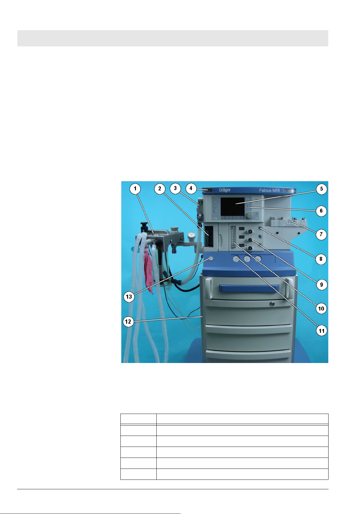
Fig. 1 Front view of Fabius MRI anesthesia system, for legend see
Table 1
Table 1 Legend to Fig. 1
No. Name
1 Breathing system Cosy 2.6
2 Lung ventilator
3 Oxygen flowmeter (auxiliary)
4 Additional alarm lights
5 Display
5330.660
Copyright reserved.
1.0_Printed on_09.01.08_F5330660_Function_Description.fm
Page 15
Fabius MRI Function description
No. Name
6 Control panel
7 Anesthetic vaporizer mount
8 Pipeline supply manometers
9 Flow control valves
10 Total fresh gas flowmeter
11 Cylinder Manometer
12 Trolley
13 O
flush key
2
Copyright reserved.
1.0_Printed on_09.01.08_F5330660_Function_Description.fm
5330.660
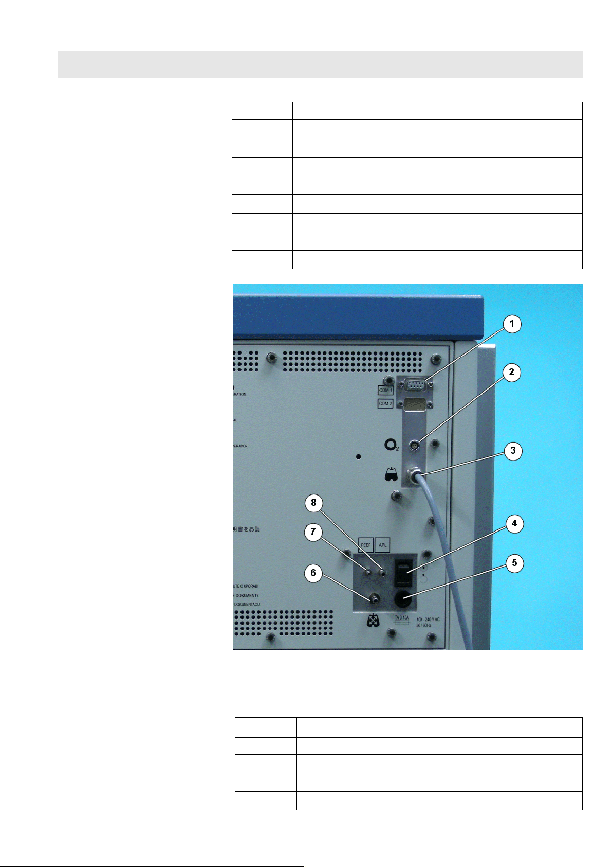
Fig. 2 Rear view with interface plate; legend, see Tab le 2
Table 2 Legend to Fig. 2
No. Name
1 Serial communication ports
2 O2 sensor connection
3 Spirolog sensor cable
4 ON/OFF switch
15
Page 16
Function description Fabius MRI
No. Name
5 Battery fuse
6 Airway pressure connection
7 Tube connection for PEEP valve
8 Tube connection for APL bypass valve
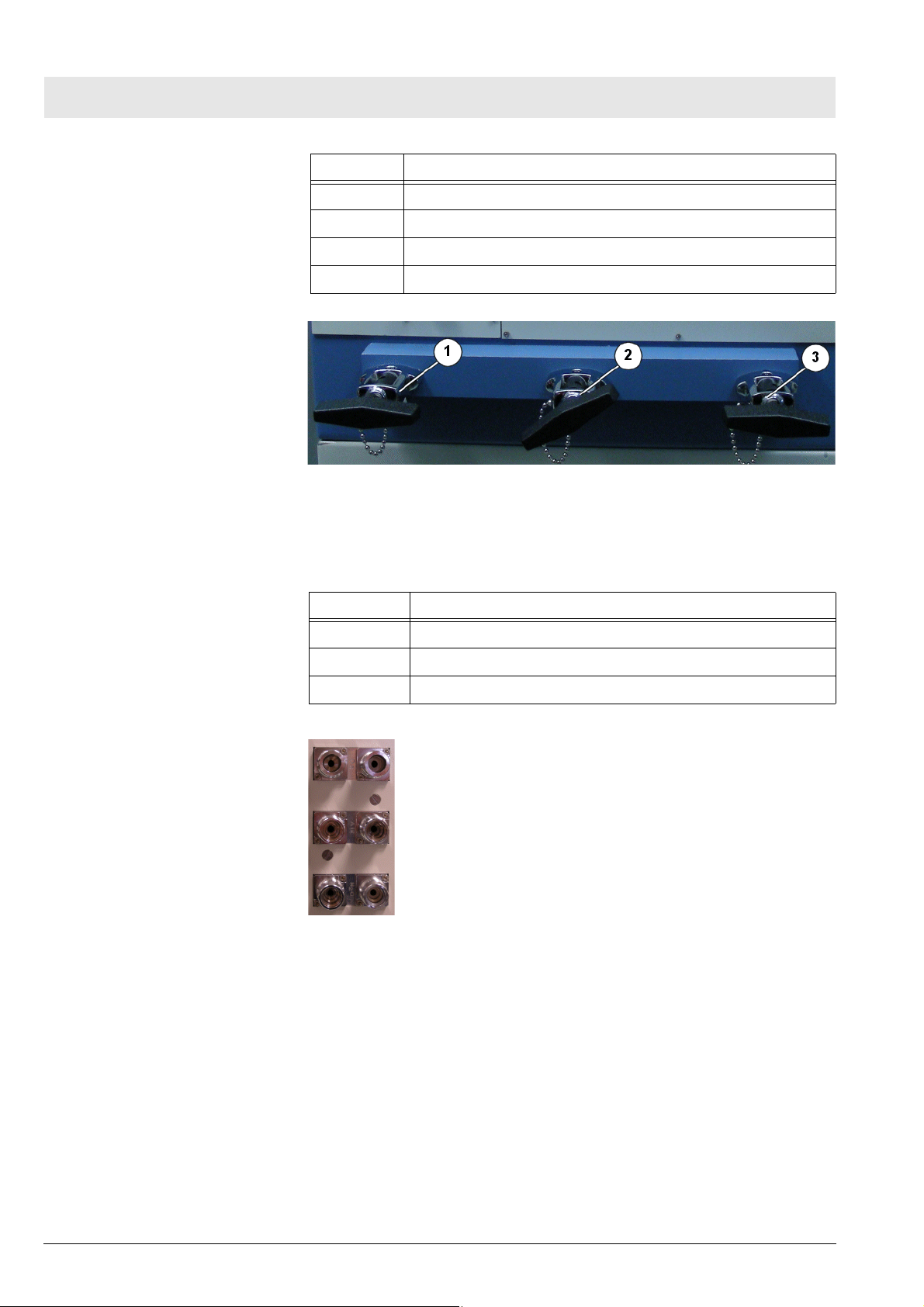
Fig. 3 Rear view showing gas pipeline and PIN index cylinder connec-
tions, for legend see Tab le 3
Table 3 Legend to Fig. 3
No. Name
1 N2O PIN index cylinder connection
2 O2 or AIR PIN index cylinder connection
3 O2 PIN index cylinder connection
Fig. 4 Central tube connections and high-pressure connections
16
5330.660
Copyright reserved.
1.0_Printed on_09.01.08_F5330660_Function_Description.fm
Page 17
Fabius MRI Function description
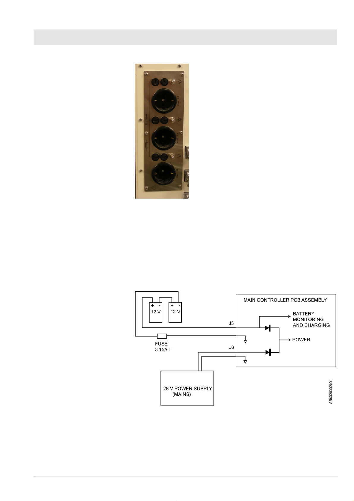
Fig. 5 Multiple socket strip
6 Battery backup Fabius MRI battery power is provided by two rechargeable series-connected
12 V batteries. These batteries remain on charge as long as the machine is
plugged into an active AC outlet. Should power supply fail while the machine
is in operation, the batteries will allow the machine to continue operating for a
minimum of 45 minutes, provided that the batteries are fully charged.
The batteries are accessible by opening the ventilator compartment. The
3.15A battery fuse is located at the back of the control box.
Copyright reserved.
1.0_Printed on_09.01.08_F5330660_Function_Description.fm
5330.660
Fig. 6 Battery backup arrangement
17
Page 18
Function description Fabius MRI
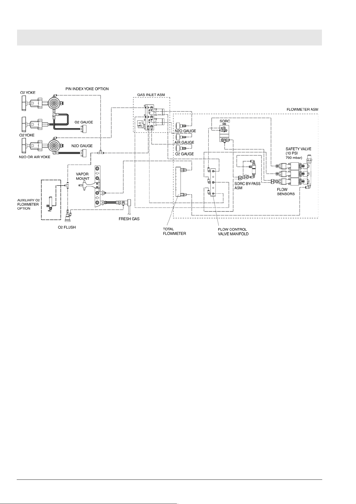
7 Fabius MRI Piping
Diagram
Fig. 7 Fabius MRI piping diagram, variant US 2-Gas
8 Function descrip-
tion of the gas box
The supply gases flow through the filters and non-return valves in the gas
inlet assembly. Pipeline supply pressures are indicated on pipeline pressure
gauges located on the flowmeter assembly. Cylinder pressure gauges are
located on the trolley assembly. The pressures of O2 and N2O delivered to
the flowmeter assembly are set by regulators on the gas inlet assembly.
If the O2 supply fails or its pressure decreases below a certain limit, the O2
low alarm switch generates an alarm.
18
5330.660
Copyright reserved.
1.0_Printed on_09.01.08_F5330660_Function_Description.fm
Page 19
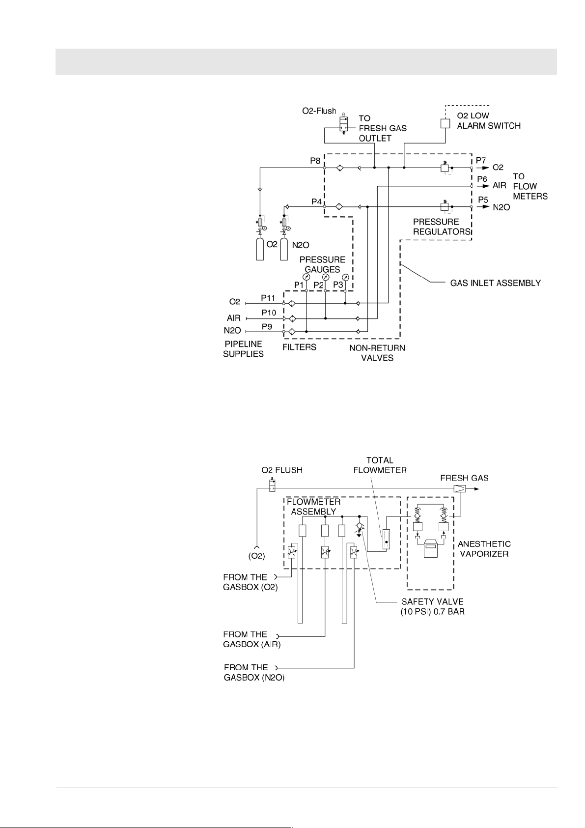
Fabius MRI Function description
Fig. 8 Gas Box Function Diagram, part 1
If the O2 flush button is pressed, oxygen is delivered to the fresh-gas outlet.
The fresh-gas ejector prevents the fresh gas from flowing back into the anesthetic vaporizer. This avoids an increase in anesthetic gas concentration.
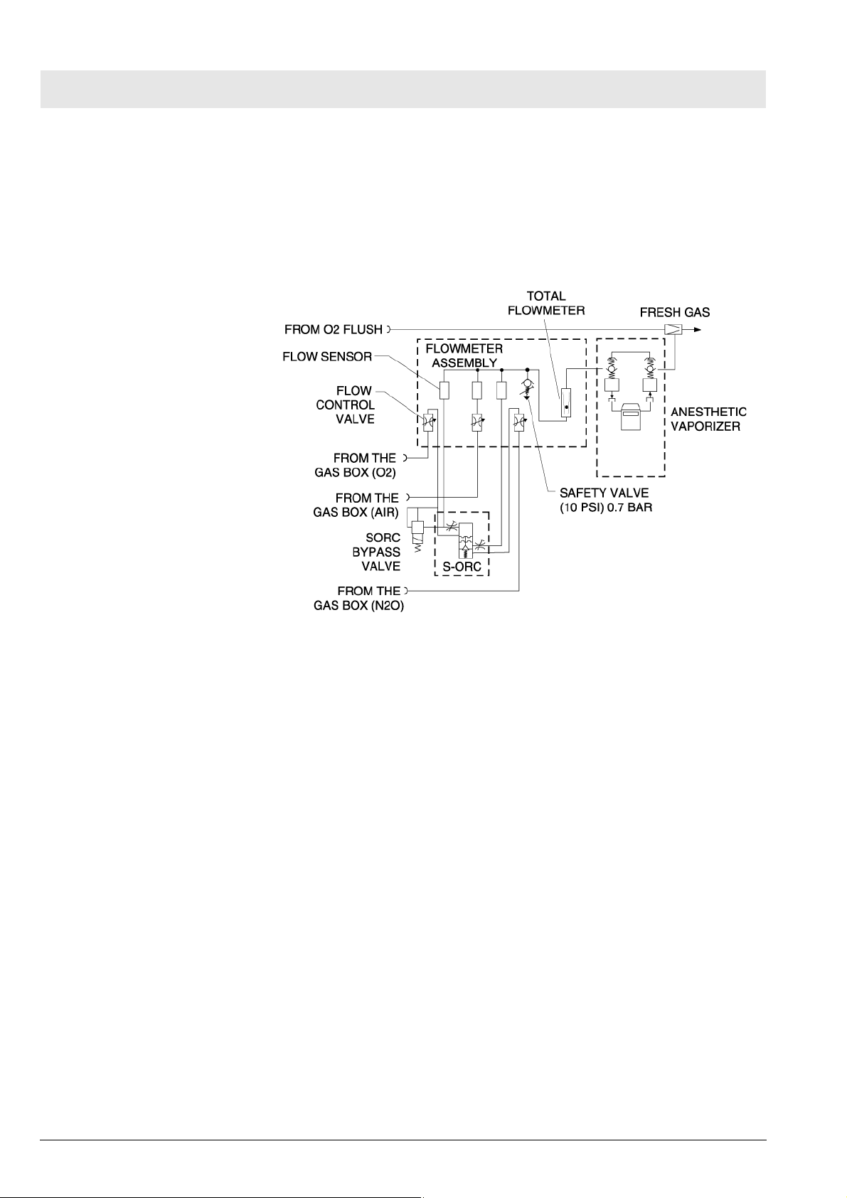
9 SORC (Sensitive
Oxygen Ratio Controller)
Copyright reserved.
1.0_Printed on_09.01.08_F5330660_Function_Description.fm
5330.660
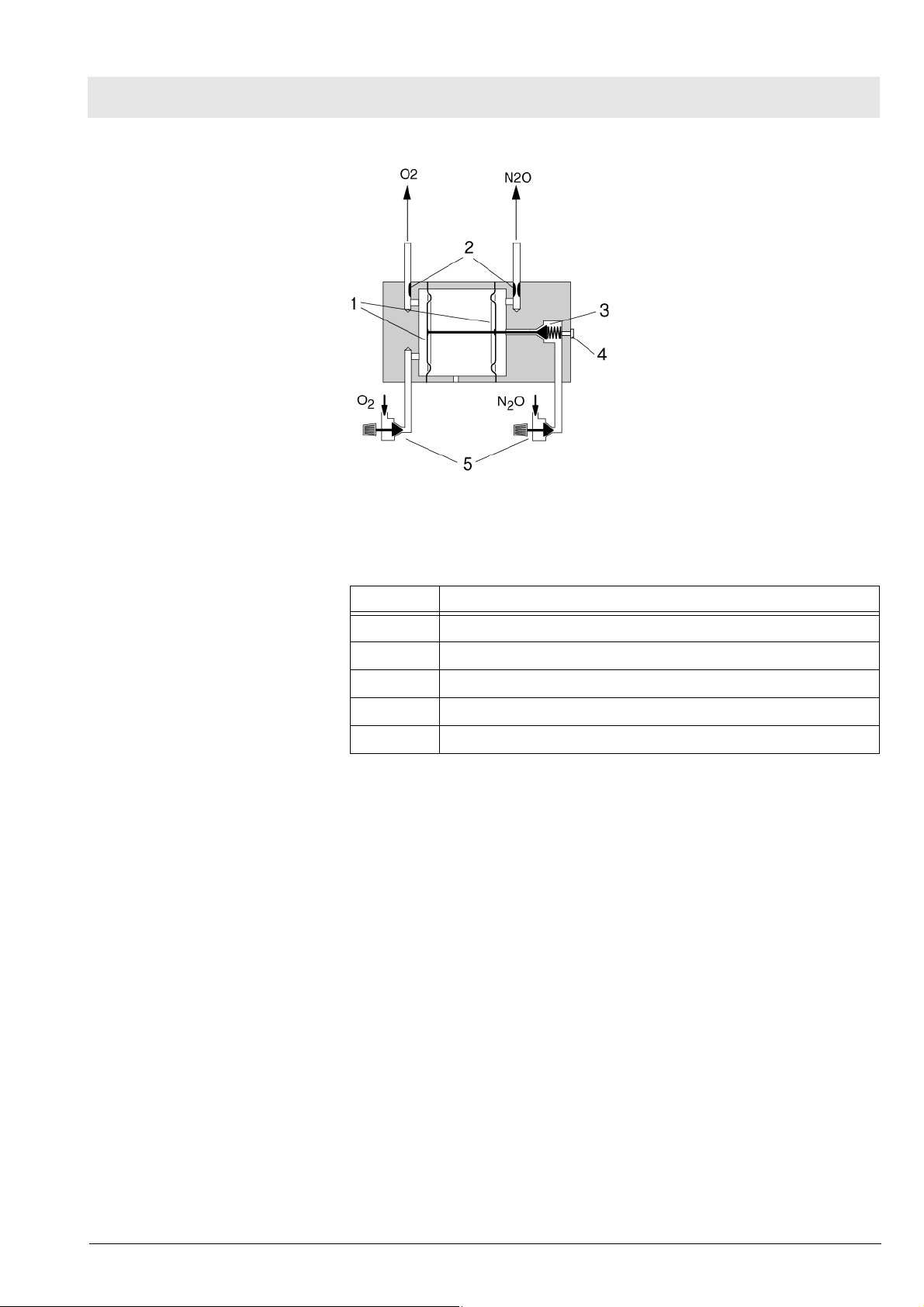
Fig. 9 Gas Box Function Diagram, part 2
The SORC is a control element that functions like an N2O shut-off device and
ensures a vital O2 concentration in the fresh gas. In the event of an O2 shortage, the SORC limits the N2O flow such that the O2 concentration in the
fresh gas does not decrease below 21 vol.%.
19
Page 20
Function description Fabius MRI
If the O2 flow control valve is closed or if the O2 flow is lower than or equal to
200 mL/min, the SORC interrupts the N2O flow.
N2O can be added as of an O2 flow of approx. 300 mL/min. In this case, the
SORC also prevents O2 concentrations below 21 vol.%.
The SORC bypass allows the oxygen to bypass the resistor in the SORC
when O2 flows above 10 L/min are needed.
Fig. 10 SORC function diagram, part 1
The O2 and N2O flows are adjusted with the flow control valves.
Resistors located at the outlets of the SORC generate back-pressures. These
back-pressures exert a force on the control diaphragms of the SORC. The O2
back-pressure opens the SORC. The N2O back-pressure closes the SORC.
The pressure ratio at the control diaphragm affects the N2O flow.
The resistors and the spring force are dimensioned such that a minimum concentration of 21 vol.% of O2 is always ensured. The maximum O2 flow is
approx. 12 L/min.
20
5330.660
Copyright reserved.
1.0_Printed on_09.01.08_F5330660_Function_Description.fm
Page 21
Fabius MRI Function description
Fig. 11 SORC function diagram, part 2, for legend see Tab l e 4
10 Cosy 2.6 breathing
system
Table 4 Legend to Fig. 11
No. Name
1 Control diaphragms
2Resistors
3 N2O non-return valve
4 Operating-point adjusting screw
5 Flow control valves
The Cosy 2.6 breathing system allows three modes of patient ventilation:
– Manual ventilation and spontaneous breathing
– Volume controlled ventilation
– Pressure controlled ventilation
On APL valves with control knob, switching from “IPPV/SPONT” to “MAN” is
carried out by turning the knob.
In the “MAN” position, the breathing system is closed to atmosphere. This
position is used for manual ventilation of the patient. The APL valve opening
pressure can be adjusted from 5 to 70 cmH2O (mbar).
Copyright reserved.
1.0_Printed on_09.01.08_F5330660_Function_Description.fm
5330.660
In the “SPONT” switch position the APL valve is open to atmosphere. This
position is used for spontaneous breathing.
Using the control box and the PEEP/Pmax valve, the pressure limit (Pmax)
can also be adjusted during volume control from 15 cmH2O (mbar) to
70 cmH2O (mbar) via the membrane keypad.
21
Page 22
Function description Fabius MRI
22
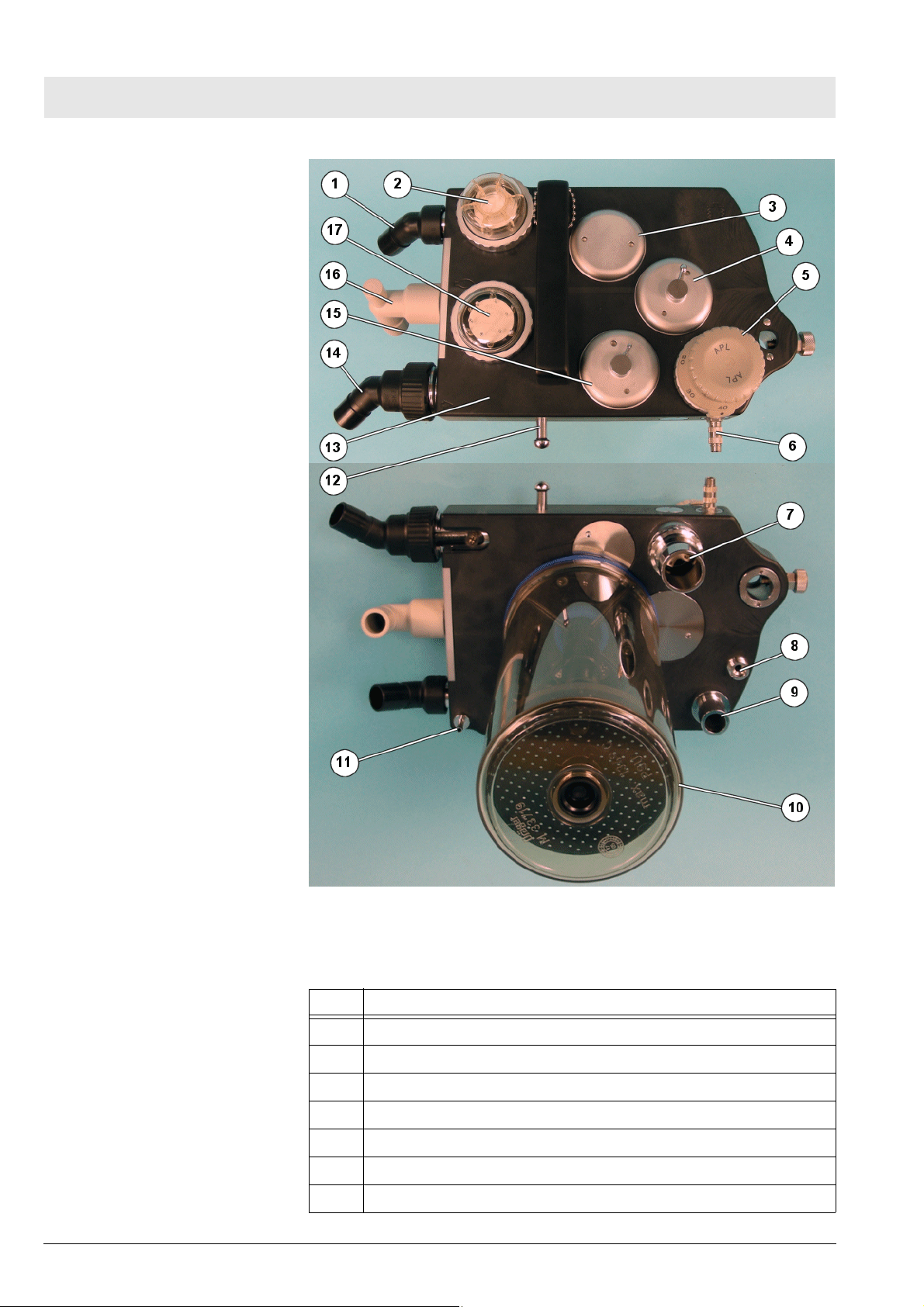
Fig. 12 Cosy 2.6 breathing system, for legend see Tab l e 5
Table 5 Legend to Fig. 12
No. Name
1 Inspiratory connection
2 Inspiratory valve and O2 sensor connection
3 Fresh-gas decoupling valve
4 APL bypass valve
5 MAN/SPONT APL valve
6 Sample gas connection
7 Anesthetic gas scavenging port
5330.660
Copyright reserved.
1.0_Printed on_09.01.08_F5330660_Function_Description.fm
Page 23

Fabius MRI Function description
No. Name
8 Fresh-gas port
9 Lung ventilator port
10 Absorber
11 Pressure sensor connection
12 Breathing bag hook
13 Flow sensor (Spirolog) (not shown)
14 Expiratory connection
15 PEEP/Pmax valve
16 Breathing bag terminal and standby holder for Y-piece
17 Expiratory valve
Copyright reserved.
1.0_Printed on_09.01.08_F5330660_Function_Description.fm
5330.660
23
Page 24
Function description Fabius MRI
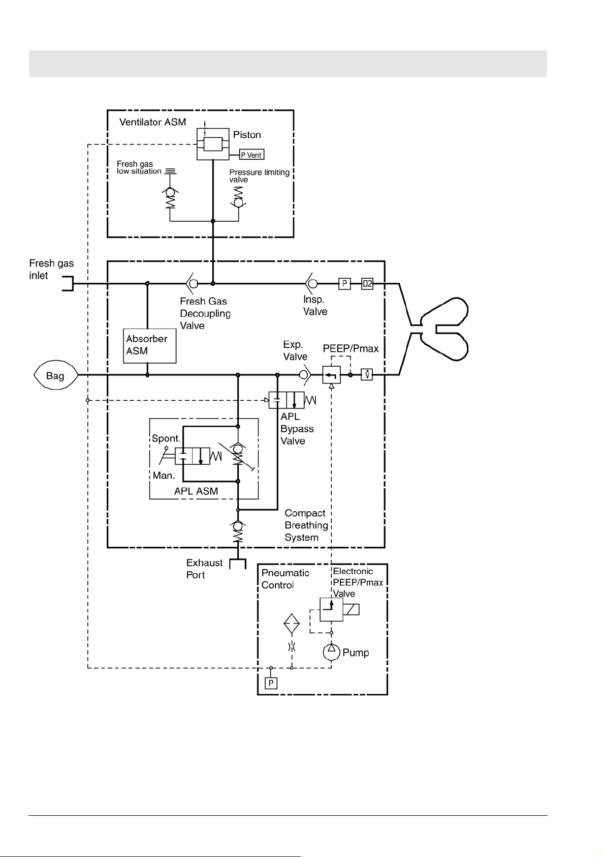
Fig. 13 Function diagram of Fabius MRI - Cosy 2.6 breathing system
24
5330.660
Copyright reserved.
1.0_Printed on_09.01.08_F5330660_Function_Description.fm
Page 25
Fabius MRI Function description
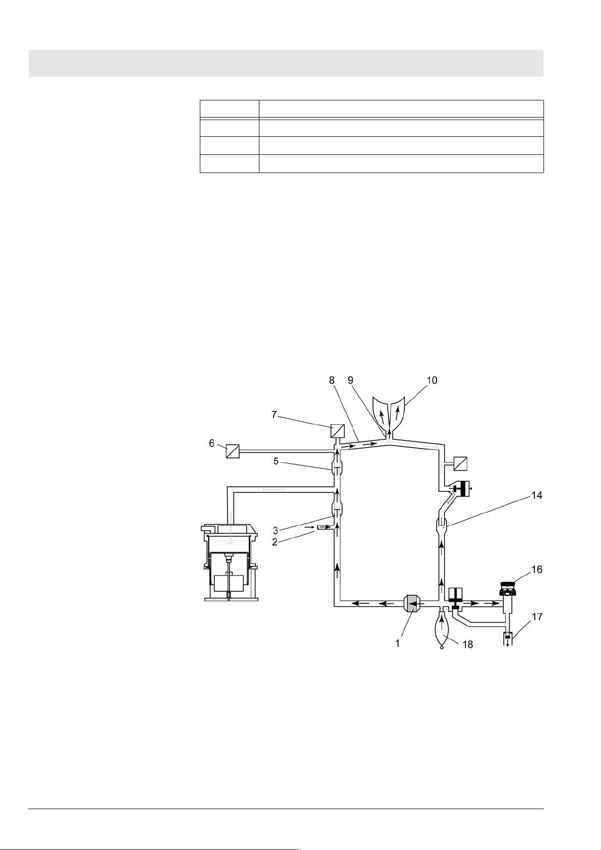
10.1 Ventilation mode
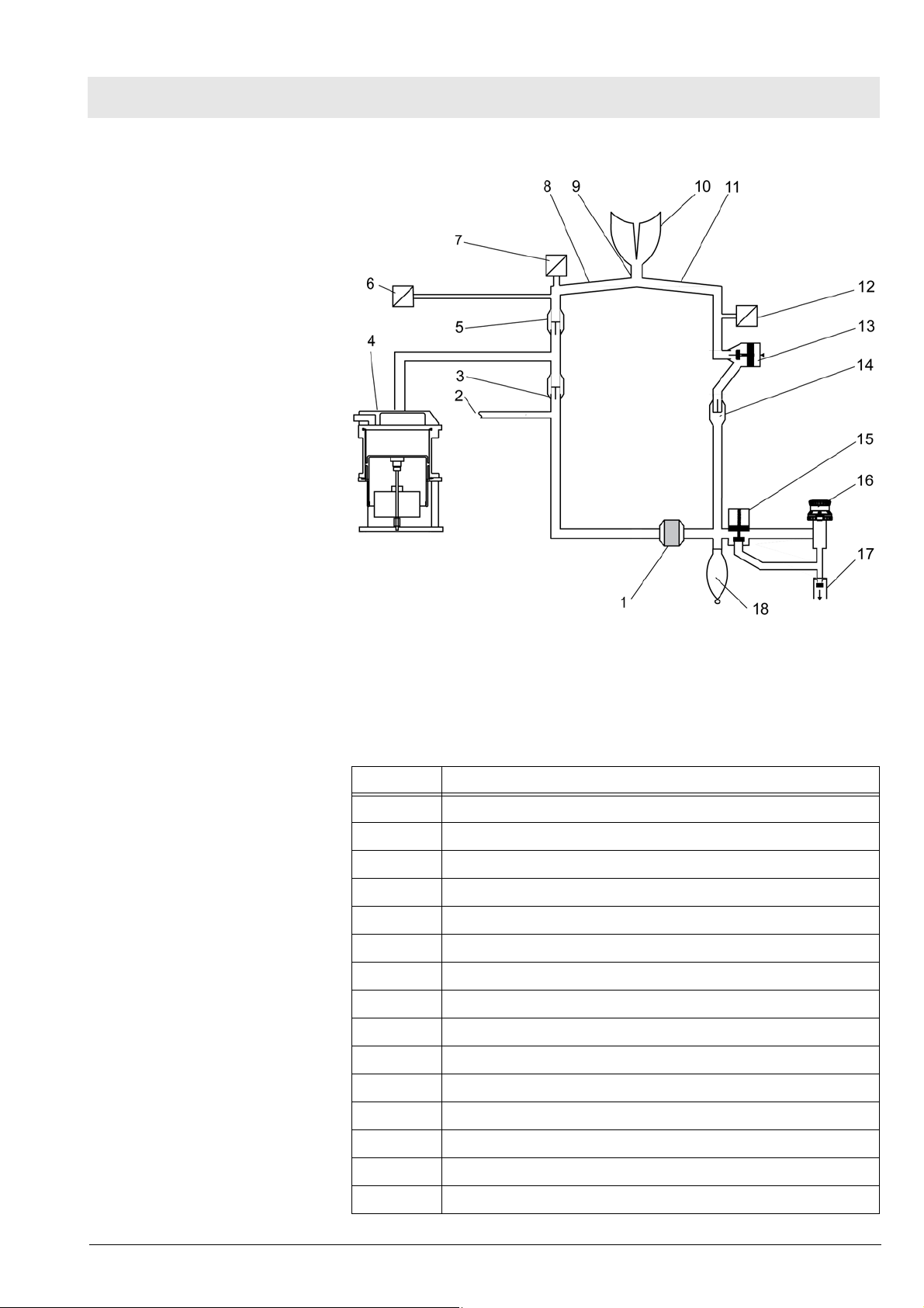
Fig. 14 Functional diagram of the ventilation mode, for legend see Tab le
6
Table 6 Legend to Fig. 14, Fig. 15, Fig. 16, Fig. 17, Fig. 18, Fig. 19,
Fig. 20
No. Name
1 Absorber
2 Fresh gas inlet
3 Fresh-gas decoupling
4 Lung ventilator
5 Inspiratory valve
6 Pressure sensor
7 Oxygen sensor
8 Inspiratory tube
9Y-piece
10 Lung
11 Expiratory tube
Copyright reserved.
1.0_Printed on_09.01.08_F5330660_Function_Description.fm
5330.660
12 Flow sensor
13 PEEP/Pmax valve
14 Expiratory valve
15 APL bypass valve
25
Page 26
Function description Fabius MRI
No. Name
16 APL valve
17 Non-return valve
18 Manual breathing bag
10.2 Manual ventilation
Manual ventilation: General
Manual ventilation: Inspiration
During manual ventilation, the APL valve is set to the “MAN” position. The
safety valve of the patient system is activated.
The item numbers mentioned in the following paragraphs refer to Fig. 15.
During inspiration, expiratory valve 14 remains closed. When the operator
compresses the manual breathing bag 18 the gas mixture (expiratory gas
and fresh gas 2) flows through the absorber 1, the fresh-gas decoupling valve
3, the inspiratory valve 5, the O2 sensor 7, the inspiratory hose 8, and the Ypiece 9 into the patient’s lung 10. The pressure sensor 6 measures the airway pressure. The ventilation pressure is limited by the APL valve 16. Any
excess amount of the gas mixture flows through the APL valve and the nonreturn valve 17 to the anesthetic gas scavenging system.
26
Manual ventilation: Expiration
Fig. 15 Manual ventilation (inspiration) - Cosy 2.6 breathing system; for
legend see Tab l e 6
During expiration, the inspiratory valve remains closed thus preventing the
expiratory gas from flowing back into the inspiratory branch.
The item numbers mentioned in the following paragraphs refer to Fig. 16.
5330.660
Copyright reserved.
1.0_Printed on_09.01.08_F5330660_Function_Description.fm
Page 27
Fabius MRI Function description
After releasing the breathing bag 18, the expiratory gas from the lung 10
flows through the expiratory tube 11, the flow sensor 12, the PEEP/Pmax
valve 13, the expiratory valve 14, into the manual ventilation bag and through
the absorber 18. At the same time, new fresh gas 2 flows into the manual
ventilation bag.
10.3 Spontaneous breathing
Spontaneous breathing:
General
Spontaneous breathing:
Inspiration
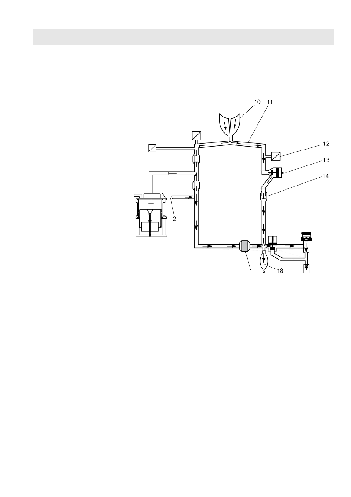
Fig. 16 Manual ventilation (expiration) - Cosy 2.6 breathing system; for
legend see Table 6
A prerequisite for spontaneous breathing is that the patient is supplied with a
sufficient amount of fresh gas. The APL valve selector must be set to the
“SPONT” position. No pressure builds up in the compact breathing system.
During inspiration, the expiratory valve remains closed thus preventing
rebreathing of expiratory gas containing CO2.
The item numbers mentioned in the following paragraphs refer to Fig. 17.
The patient inhales the gas mixture (expiratory gas and fresh gas 2) from the
manual ventilation bag 18. The gas mixture flows through the fresh-gas
decoupling valve 3, the inspiratory valve 5, the O2 sensor 7, the inspiratory
hose 8, and through the Y-piece 9 into the lung 10. The pressure sensor 6
measures the airway pressure.
Copyright reserved.
1.0_Printed on_09.01.08_F5330660_Function_Description.fm
5330.660
27
Page 28

Function description Fabius MRI
Spontaneous breathing:
Expiration
Fig. 17 Spontaneous (inspiration) - Cosy 2.6 breathing system; for leg-
end see Table 6
During expiration, the inspiratory valve remains closed thus preventing the
expiratory gas from flowing back into the inspiratory branch.
The item numbers mentioned in the following paragraphs refer to Fig. 18.
The APL valve 16 is open, irrespective of its pressure setting.
The expiratory gas flows from the lung 10 through the expiratory tube 11, the
flow sensor 12, the PEEP control valve 13, the expiratory valve 14, the manual ventilation bag 18 and through the absorber 1. At the same time, new
fresh gas 2 flows into the manual ventilation bag.
When the manual ventilation bag is full, any excess gas mixture flows through
the non-return valve 17 into the anesthetic gas scavenging system.
28
5330.660
Copyright reserved.
1.0_Printed on_09.01.08_F5330660_Function_Description.fm
Page 29

Fabius MRI Function description
10.4 Volume/pressure
control ventilation
mode
Volume control ventilation
mode: General
Volume/pressure control
ventilation mode: Inspiration
Fig. 18 Spontaneous (expiration) - Cosy 2.6 breathing system; for leg-
end see Tab le 6
A prerequisite for volume control ventilation is that the patient is supplied with
a sufficient amount of fresh gas.
The APL bypass valve opens in volume control mode, allowing excess gas to
be vented to the scavenging system regardless of the MAN-SPONT valve
setting.
The safety valve of the patient system makes sure that no pressures greater
than 75 cmH2O build up in the system.
During ventilation, the pressure limit (Pmax) can adjusted on the control box.
During inspiration, the PEEP/Pmax valve remains closed. The control pressure present at the PEEP/Pmax valve varies with the set pressure limit
(Pmax).
The item numbers mentioned in the following paragraphs refer to Fig. 19.
Copyright reserved.
1.0_Printed on_09.01.08_F5330660_Function_Description.fm
5330.660
The pressure generated by the piston 4 of the lung ventilator closes the freshgas decoupling valve 3. The gas mixture (expiratory gas and fresh gas 2)
flows through the inspiratory valve 5, the O2 sensor 7, the inspiratory tube 8,
and the Y-piece 9 into the lung 10. The pressure sensor 6 measures the air-
29
Page 30

Function description Fabius MRI
way pressure. The ventilation pressure cannot exceed the pressure limit
(Pmax) set on the control box because the PEEP/Pmax valve 13 opens. The
fresh gas then fills the manual ventilation bag 18.
Any excess fresh-gas flows through the open APL bypass valve 15, and the
non-return valve 17 into the anesthetic gas scavenging system.
Volume/pressure control
ventilation mode: Expiration
Fig. 19 Volume control ventilation (inspiration) - Cosy 2.6 breathing sys-
tem; for legend see Tabl e 6
During expiration, the inspiratory valve remains closed thus preventing
rebreathing into the inspiratory branch.
The item numbers mentioned in the following paragraphs refer to Fig. 20.
The expiratory gas from the lung 10 flows through the expiratory tube 11, the
flow sensor 12, the PEEP/Pmax valve 13, the expiratory valve 14, and the
absorber 18 back into the manual ventilation bag 18 mixing with fresh gas 2
also flowing into the manual ventilation bag.
The lung ventilator's piston 4 moves back drawing the gas mixture needed for
the next inspiration into the piston space.
Any excess fresh-gas flows through the open APL bypass valve 15, and the
non-return valve 17 into the anesthetic gas scavenging system.
30
5330.660
Copyright reserved.
1.0_Printed on_09.01.08_F5330660_Function_Description.fm
Page 31

Fabius MRI Function description
Fig. 20 Volume control ventilation (expiration) - Cosy 2.6 breathing sys-
tem; for legend see Table 6
10.5 Cosy 2.6 absorber The absorber canister is filled with fresh soda lime. The CO2 is scrubbed
from the expiratory gas by the soda lime.
CAUTION
Expired soda lime changes its color. The soda lime must be replaced when
two thirds of the soda lime in the absorber canister is discolored.
11 Lung ventilator The ventilator is located in a swing-out compartment at the left side of the
Fabius Tiro M. A hose terminal is provided on the left side of the compartment
for connection to the breathing system. Fresh gas is delivered to the patient
by a piston that is driven by a motor and ball-screw arrangement. A sight window on the compartment allows the operator to verify movement of the piston.
Two diaphragms (upper and lower) comprise a bag-type rolling seal that surrounds the piston. Vacuum from the pneumatic assembly (described in a later
paragraph) is provided between the outside of the seal and the cylinder, to
ensure proper operation of the seal during piston movement.
During inspiration, the lung ventilator delivers fresh gas at a given volume,
pressure and frequency. These parameters are set at the control panel. Refer
to the Operator’s Manual for details on ventilator settings, displays and controls. During expiration, the bag-type rolling seal fills with expired gas from the
patient and with fresh gas stored in the breathing bag.
Copyright reserved.
1.0_Printed on_09.01.08_F5330660_Function_Description.fm
5330.660
31
Page 32

Function description Fabius MRI
The lung ventilator motor is powered from the Control PCB. A position sensor
on the ventilator signals the Control PCB when the piston reaches its lower
limit. An incremental encoder on the motor shaft determines the number of
revolutions and provides piston travel information to the Control PCB.
Lung ventilator pressure is monitored by a transducer on the Control PCB.
When the auxiliary-air valve on the patient system opens, a fresh-gas low
alarm is generated, provided that it has been enabled in the service mode.
The pressure sensor is the same type as the one used for measuring airway
pressure. A tube connects the pressure sensor’s positive pressure port to a
connector located on the top cover of the ventilator. The purpose of this sensor is to allow the software to sense when a condition exists that would cause
the ventilator's auxiliary air valve to open. The threshold that is used by the
software for this condition is -8 mbar. In normal use the primary cause for this
condition is an insufficient amount of reserve gas in the manual breathing
bag. The operator is alerted when this condition exists, with a medium priority
"Fresh gas low" alarm. This alarm can be disabled in service mode.
32
5330.660
Copyright reserved.
1.0_Printed on_09.01.08_F5330660_Function_Description.fm
Page 33

Fabius MRI Function description
Fig. 21 Ventilator (piston shown in ‘down’ position), for legend see Table 7
Table 7 Legend to Fig. 21
No. Name
1 Top section of housing
2 Pressure limiting valve
3 Auxiliary-air valve
4 Pressure sensor line to the Control PCB
5 Vacuum line to the pneumatic assembly
6 Patient seal
7Piston
Copyright reserved.
1.0_Printed on_09.01.08_F5330660_Function_Description.fm
5330.660
33
Page 34

Function description Fabius MRI
No. Name
8 Lower diaphragm
9 Motor/ballscrew assembly
10 Incremental encoder
The top of the ventilator assembly (patient system) contains two valves:
11.1 Pressure limiting
valve
If the pressure limit control fails, the ventilator's safety valve limits the gas
pressure. This valve opens at approximately 75 cmH2O (mbar).
Fig. 22 Sectional view of the safety valve, for legend see Ta b l e 8
Table 8 Legend to Fig. 22
No. Name
1Screw
2Spring
3 Washer
4 Valve disc
11.2 Auxiliary-air valve The auxiliary air valve allows the patient to spontaneously breathe ambient
air should the medical gas supply and/or Fabius MRI fail.
34
5330.660
Copyright reserved.
1.0_Printed on_09.01.08_F5330660_Function_Description.fm
Page 35

Fabius MRI Function description
Fig. 23 Sectional view of the auxiliary air valve, for legend see Table 9
Table 9 Legend to Fig. 23
No. Name
1 Threaded ring
2 Valve seat
3 Valve disc
4 Valve cross with spring
12 Pneumatic assembly The pneumatic assembly provides pressure for the PEEP valve control, and
also provides vacuum for the ventilator bag-type rolling seals and the APL
bypass valve control.
The pump and the PEEP valve are shielded separately.
12.1 PEEP/Pmax valve
control
When the Fabius MRI is operating in the automatic ventilation mode, the
pump on the pneumatic assembly is running, and the electronic PEEP valve
is actuated by the Control PCB. The current supplied to the coil of the electronic PEEP valve is proportional to the set PEEP value, and controls the
position of the diaphragm within the electronic PEEP valve. This then determines the control pressure applied to the proportional PEEP valve in the
breathing system, which maintains the desired amount of PEEP during
patient expiration. The V1 reservoir smooths out pressure variations caused
by the pump. See Fig. 24.
Copyright reserved.
1.0_Printed on_09.01.08_F5330660_Function_Description.fm
5330.660
35
Page 36

Function description Fabius MRI
Fig. 24 Schematic of the pneumatic control
12.2 APL bypass valve
control
When the Fabius MRI is operating in the automatic ventilation mode, the
pneumatic assembly provides a vacuum signal to hold open the APL bypass
valve in the breathing system. The V2 reservoir and filter provide noise damping, and the variable restrictor is used to set the vacuum level in the range of
–150 to –240 cmH2O (mbar).
When the machine is operating in the manual ventilation mode, the pump on
the pneumatic assembly (and the ventilator) is stopped, and the springloaded APL bypass valve in the breathing system closes, directing exhaled
gas through the APL valve.
13 Control PCB The Control PCB is designed as an MRI shielded assembly.
The connections to the components are routed via P-filters, motor filters and
shielded cables.
The shielded assembly is not opened for servicing!
36
5330.660
Copyright reserved.
1.0_Printed on_09.01.08_F5330660_Function_Description.fm
Page 37

Fabius MRI Function description
14 Function Descrip-
tion: Control PCB
Copyright reserved.
1.0_Printed on_09.01.08_F5330660_Function_Description.fm
5330.660
Fig. 25 Electrical Block Diagram
The Control PCB contains the following functions:
– Motor control and monitoring
– Measurement of O2 and flow parameters
– Provision of one or two serial interfaces
– Evaluation of the O2 low signal
– Measurement and display of fresh-gas parameters
– PEEP valve control
– Pump control
– Front panel display control
– Evaluation of keypad and rotary encoder
– The required supply voltages are supplied by the power supply unit.
37
Page 38

Function description Fabius MRI
Fig. 26 Controller functional block diagram
15 Control panel
assembly
The control panel comprises a 6.5” graphical display, a membrane keypad, a
rotary encoder, the front frame and a loudspeaker.
The display has a shield. The connection from the Control PCB (Cu shield) to
the display is routed via shielded round cables and D-Sub connectors.
Data and power for the display comes from the Control PCB via a 20-conductor ribbon cable. The keypad interface is connected to the Control PCB by a
30-conductor ribbon cable. A block diagram of the control panel assembly is
shown in the following illustration.
The shielded display assembly is not opened for servicing.
38
5330.660
Copyright reserved.
1.0_Printed on_09.01.08_F5330660_Function_Description.fm
Page 39

Fabius MRI Function description
Fig. 27 Control panel block diagram
Copyright reserved.
1.0_Printed on_09.01.08_F5330660_Function_Description.fm
5330.660
Fig. 28 Fabius MRI control panel (“Standby” screen shown), for legend
see Table 10
Table 10 Legend to Fig. 28
Item Function
1 Selects volume controlled ventilation mode
Refer to Operator’s Manual
2 Selects pressure controlled ventilation mode
Refer to Operator’s Manual
3 Pressure Support
4SIMV
6 Places the ventilator in MAN/SPONT mode
Refer to Operator’s Manual
7 Programmable keys: activate the corresponding function that
appears on screen above the key
39
Page 40

Function description Fabius MRI
Item Function
8 For setting alarm limits
Refer to Operator’s Manual
9 Setup key: activates sub-screens for monitoring functions.
Refer to Operator’s Manual
10 Home key: returns display to main screen shown before standby
11 Rotary encoder: moves the cursor on the screen; confirms selec-
tion when pressed
12 Alarm status indicators:
Flashing red: Warning; flashing yellow: Caution; solid yellow: Note
13 Alarm silence key: silences all active alarms for two minutes
14 Power ON indicator: lighted when machine is plugged into an
active AC outlet
15 Switches the unit back to standby mode
16 FiO2 measurement The O2 sensor measures the O2 concentration in the respiratory gas (FiO2).
The O2 sensor contains a capsule with alkaline electrolyte, a lead anode, two
gold cathodes, and a Teflon membrane. The spatial separation of the two
gold cathodes allows to carry out a voltage comparison.
The O2 sensor is an electrochemical cell that generates a voltage which varies with the O2 concentration.
40
Fig. 29 O2 sensor, for legend see Table 11
Table 11 Legend to Fig. 29
No. Name
1 Teflon membrane
2 Gold cathode A
3 Lead anode
5330.660
Copyright reserved.
1.0_Printed on_09.01.08_F5330660_Function_Description.fm
Page 41

Fabius MRI Function description
No. Name
4 Temperature compensation resistors
5 Alkaline electrolyte
6 Gold cathode B
The O2 to be measured diffuses through the Teflon membrane, undergoes a
chemical reaction at the gold cathodes (negative) and produces lead oxide
and water at the lead anode (positive). During this chemical process, a
voltage is generated that is proportional to the O2 partial pressure.
The internal resistance of the cell is determined by the surface of the gold
cathodes, the O2 diffusion velocity, and the distance between the gold cathodes and the lead anode. This resistance is approximately 700 ohms.
The chemical process is temperature-sensitive. Therefore, thermistors are
connected in parallel to the O2 sensor. These resistors and the internal resistor of the O2 sensor correct the measuring voltage. Since two cathodes are
used in the O2 sensor cell, two different voltages are generated. These voltages are compared with each other. If their difference exceeds a certain
value, the machine prompts the operator to check the cell.
17 Respiratory flow
measurement
If the O2 sensor fails, the control box will indicate an error on the graphics
display.
The flow sensor functions according to the constant temperature hot-wire
anemometer principle. Respiratory gas flows past a thin platinum wire. This
platinum wire (A) is located in a measuring tube and is electrically heated.
The platinum wire is held at a constant temperature. Gas flow removes heat
from the hot wire. The higher the gas flow rate, the greater the heat removal.
The amount of electrical current needed to maintain a constant platinum wire
temperature is thus proportional to the gas flow rate.
A second platinum wire (B) inside the measuring tube is used for temperature
compensation.
Internal calibration tables for O2/N2O mixtures, Air and 100% O2 are used to
linearize the measured flow.
Copyright reserved.
1.0_Printed on_09.01.08_F5330660_Function_Description.fm
5330.660
Fig. 30 Respiratory flow sensor, for legend see Table 12
41
Page 42

Function description Fabius MRI
Table 12 Legend to Fig. 30
No. Name
“A” Platinum wire “A”
“B” Platinum wire “B”
18 Gas flow rate mea-
surement
The gas flows past a heated wire, cooling it. The current necessary to keep
the temperature of the wire constant is a measure of the flow.
Fig. 31 Details of the flow sensor, for legend see Table 13
Table 13 Legend to Fig. 31
No. Name
1 Tube connector
2 Electronic components
3 Electrical connection
4 Gas outlet port (to manifold)
5 Mounting pole
6 Gas inlet assembly
Copyright reserved.
1.0_Printed on_09.01.08_F5330660_Function_Description.fm
42
5330.660
Page 43

Fabius MRI Function description
Fig. 32 Gas flow through sensors, for legend see Table 14
19 Anesthetic vapor-
izer(s)
Table 14 Legend to Fig. 32
No. Name
1 From the oxygen flow control valve
2 From the Air flow control valve
3 From the N2O flow control valve
4 Fresh-gas flow to the total fresh-gas flowmeter
5 Fresh-gas manifold
Refer to separate technical documentation of the anesthetic vaporizer.
Copyright reserved.
1.0_Printed on_09.01.08_F5330660_Function_Description.fm
5330.660
43
Page 44

Function description Fabius MRI
44
5330.660
Copyright reserved.
1.0_Printed on_09.01.08_F5330660_Function_Description.fm
Page 45

Maintenance Procedures
45
Page 46

Diagnostics Fabius MRI
1 Diagnostics
NOTE
The screen illustrations contained in this section are for reference only and
therefore may or may not reflect the software version currently installed.
The Fabius MRI diagnostic system monitors and records the status of its
internal hardware when the machine is turned on. The status of each test is
displayed on the power-up screen as shown in Fig. 1. This screen is displayed for several seconds before proceeding to the Standby screen. The
power-up screen also displays one of three messages at completion of the
diagnostics:
FUNCTIONAL This message indicates that the Fabius MRI has
passed all power-up tests and is fully functional. The
machine will proceed to the Standby screen (Fig. 2)
after a short delay.
CONDITIONALLY
FUNCTIONAL
This message indicates that a minor problem has
been detected. The Fabius MRI may be used, but
your local authorized service organization or DrägerService should be notified to correct the problem.
Press the rotary control to proceed to the Standby
screen.
NON-FUNCTIONAL This message indicates that a serious problem has
been detected, and the machine will not proceed to
the monitor screen. Do not use the machine. Immediately notify your local authorized service organization
or DrägerService to correct the problem.
The “Preventive Maintenance Due” message will appear on the screen if the
current date exceeds the Periodic Manufacturer's Service (test procedure)
due date stored in the machine.
46
Fig. 1 Power-up diagnostics screen
5330.660
Copyright reserved.
Version 1.0_Printed on_09.01.08_W5330450_Wartung.fm
Page 47

Fabius MRI Diagnostics
Fig. 2 Standby screen
NOTE
During display of the standby screen, a 2.5-minute count-down appears on
the screen, after which the display changes to energy saving mode. Press
any key on the panel to return to the Standby screen.
Copyright reserved.
Version 1.0_Printed on_09.01.08_W533 0450_Wartung.fm
5330.660
47
Page 48

Diagnostics Fabius MRI
48
5330.660
Copyright reserved.
Version 1.0_Printed on_09.01.08_W5330450_Wartung.fm
Page 49

Annex
Parts catalog
Test List
Page 50

Page 51

Parts catalog
Fabius MRI
Revision: 00
2007-10-29
5330.660
Because you care
Page 52

Page 53

A
Parts catalog
Fabius MRI
Item
Order No. Description Qty. Qty.unit
No.
Products concerned 1.000 St
Basic unit 1.000 St
Manuals/Techn.Documentation 1.000 St
Modification kits/Options 1.000 St
Maintenance parts/Service kits 1.000 St
ccessories/Consumables 1.000 St
Remark
Copyright reserved.
Items that are shown in the illustration but are not listed below the illustration are not available as spare parts
Revision: 00
Fabius MRI
Page 54

Parts catalog
Products concerned
Item
Order No. Description Qty. Qty.unit
No.
1 8607300 Fabius MRI 1.000 St
Remark
Copyright reserved.
Items that are shown in the illustration but are not listed below the illustration are not available as spare parts
Fabius MRI
Revision: 00
Page 55

Parts catalog
Basic unit
Item
Order No. Description Qty. Qty.unit
No.
1 Basic device 1.000 St
2 Trolly 1.000 St
3 Breathing systems 1.000 St
Remark
Revision: 00
Copyright reserved.
Items that are shown in the illustration but are not listed below the illustration are not available as spare parts
Fabius MRI
Page 56

Parts catalog
Basic device
Item
Order No. Description Qty. Qty.unit
No.
1 Vaporizer holder 1.000 St
4 User interface 1.000 St
Remark
Copyright reserved.
Items that are shown in the illustration but are not listed below the illustration are not available as spare parts
Fabius MRI
Revision: 00
Page 57

Parts catalog
User interface
Item
Order No. Description Qty. Qty.unit
No.
3 M29655 CONTROL KNOB 1.000 St
Remark
Copyright reserved.
Items that are shown in the illustration but are not listed below the illustration are not available as spare parts
Fabius MRI
Revision: 00
Page 58

Parts catalog
Trolly
Item
Order No. Description Qty. Qty.unit
No.
6 MX08806 Castor 1.000 St
Remark
Copyright reserved.
Items that are shown in the illustration but are not listed below the illustration are not available as spare parts
Fabius MRI
Revision: 00
Page 59

Parts catalog
Breathing systems
Item
Order No. Description Qty. Qty.unit
No.
Breathing system COSY 2.6 1.000 St
Remark
Revision: 00
Copyright reserved.
Items that are shown in the illustration but are not listed below the illustration are not available as spare parts
Fabius MRI
Page 60

Parts catalog
IFU SW 3.n
Item
Order No. Description Qty. Qty.unit
No.
9039035 IFU Fabius MRI 3.n enUS 1.000 St
9039036 IFU Fabius MRI 3.n en 1.000 St
9039055 IfU Fabius MRI fr 1.000 St
9039056 IFU Fabius MRI de 1.000 St
9039058 IfU Fabius MRI es 1.000 St
9039059 IfU Fabius MRI it 1.000 St
9039060 IfU Fabius MRI ru 1.000 St
9039062 IfU Fabius MRI ptBras 1.000 St
9039065 IfU Fabius MRI nl 1.000 St
9039067 IfU Fabius MRI sv 1.000 St
Remark
Copyright reserved.
Items that are shown in the illustration but are not listed below the illustration are not available as spare parts
Fabius MRI
Revision: 00
Page 61

Parts catalog
Modification kits/Options
Item
Order No. Description Qty. Qty.unit
No.
Software 1.000 St
hardware 1.000 St
Remark
Revision: 00
Copyright reserved.
Items that are shown in the illustration but are not listed below the illustration are not available as spare parts
Fabius MRI
Page 62

Parts catalog
hardware
Item
Order No. Description Qty. Qty.unit
No.
vac./eject. succ.system 1.000 St
8607593 adhesive tape 40mT/400 gauss 1.000 St
Remark
Revision: 00
Copyright reserved.
Items that are shown in the illustration but are not listed below the illustration are not available as spare parts
Fabius MRI
Page 63

Parts catalog
Maintenance parts/Service kits
Item
Order No. Description Qty. Qty.unit
No.
M23225 VALVE DISK 1.000 St
6850645 O2-Sensor (Capsule) 1.000 St
8403735 Set of 5 Spirolog sensors 1.000 St
8604874 Hose Asm-PEEP/Pmax-APL Byp RHS 1.000 St
1190520 HOSE 4X1,5-SI 50 SH A NF 1.000 m
8402868 BACTERIA FILTER 1.000 St
Remark
Revision: 00
Copyright reserved.
Items that are shown in the illustration but are not listed below the illustration are not available as spare parts
Fabius MRI
Page 64

Parts catalog
Accessories/Consumables
Item
Order No. Description Qty. Qty.unit
No.
8301349 EARTHING CABLE, 3,2 M 1.000 St
8604310 hose-ventilator 110cm 1.000 St
1190520 HOSE 4X1,5-SI 50 SH A NF 1.000 m
U04314 O-RING SEAL 1.000 St
8607593 adhesive tape 40mT/400 gauss 1.000 St
2600651 DIAPHRAGM, PISTON 1.000 St
8402868 BACTERIA FILTER 1.000 St
1836722 SUPPLY MAIN 3,5M 3G1 CRSW 1.000 St
1841793 PWR Cord 10A,3m,gr,USA/J RoHS 1.000 St
8607055 Hose Asm PEEP-Pmax-APL Byp LH 1.000 St
4117266 POWER CORD ASM- 15FT FABIUS GS 1.000 St
6733895 SET MIC.FILTER 654ST-ISOCLICK 1.000 St
8604831 O-RING 105 x 4 1.000 St
8301348 EARTHING CABLE, 0,8 M 1.000 St
8604287 Fan hose right 1.000 St
1851713 Cable Great Britian,3m,10A 1.000 St
1851705 Cable Australia,3m,10A,C13 1.000 St
1851721 Power cable DK, 3 m, 10 A 1.000 St
1859714 Power cable 10A,3m,black,China 1.000 St
8604874 Hose Asm-PEEP/Pmax-APL Byp RHS 1.000 St
M23225 VALVE DISK 1.000 St
1 8403735 Set of 5 Spirolog sensors 1.000 St
2 6850645 O2-Sensor (Capsule) 1.000 St
3 8606055 O2 sensor housing, right 1.000 St
4 MK01900 SpiroLife 1.000 St
Remark
Copyright reserved.
Items that are shown in the illustration but are not listed below the illustration are not available as spare parts
Fabius MRI
Revision: 00
Page 65

Fabius MRI
Assembly
Description Part No.
Accessories/Consumables
adhesive tape 40mT/400 gauss 8607593
BACTERIA FILTER 8402868
Cable Australia,3m,10A,C13 1851705
Cable Great Britian,3m,10A 1851713
DIAPHRAGM, PISTON 2600651
EARTHING CABLE, 0,8 M 8301348
EARTHING CABLE, 3,2 M 8301349
Fan hose right 8604287
HOSE 4X1,5-SI 50 SH A NF 1190520
Hose Asm PEEP-Pmax-APL Byp LH 8607055
Hose Asm-PEEP/Pmax-APL Byp RHS 8604874
hose-ventilator 110cm 8604310
O2 sensor housing, right 8606055
O2-Sensor (Capsule) 6850645
O-RING 105 x 4 8604831
O-RING SEAL U04314
Power cable 10A,3m,black,China 1859714
Power cable DK, 3 m, 10 A 1851721
POWER CORD ASM- 15FT FABIUS GS 4117266
PWR Cord 10A,3m,gr,USA/J RoHS 1841793
SET MIC.FILTER 654ST-ISOCLICK 6733895
Set of 5 Spirolog sensors 8403735
SpiroLife MK01900
SUPPLY MAIN 3,5M 3G1 CRSW 1836722
VALVE DISK M23225
Parts catalog
Breathing system COSY 2.6
Cosy2.6 8605797
fine tuning valves
CAP 1, SW AIR (D,A,CH) M34307
CAP 1, SW O2 (D,A,CH) M34305
CAP 1,BLACK-WHITE M26205
CAP 1,BLUE M24901
CAP 1,GREEN M25147
CAP 1,SW N2O (D,A,CH) M34306
CAP 1,YELLOW M25797
CAP,WHITE M25146
ISO rotary knob without cap 8604697
Rotary knob without cap MK00360
hardware
adhesive tape 40mT/400 gauss 8607593
5330.660
Revision: 00
Page 66

Fabius MRI
Assembly
Description Part No.
IFU SW 3.n
IFU Fabius MRI 3.n en 9039036
IFU Fabius MRI 3.n enUS 9039035
IFU Fabius MRI de 9039056
IfU Fabius MRI es 9039058
IfU Fabius MRI fr 9039055
IfU Fabius MRI it 9039059
IfU Fabius MRI nl 9039065
IfU Fabius MRI ptBras 9039062
IfU Fabius MRI ru 9039060
IfU Fabius MRI sv 9039067
Maintenance parts/Service kits
BACTERIA FILTER 8402868
HOSE 4X1,5-SI 50 SH A NF 1190520
Hose Asm-PEEP/Pmax-APL Byp RHS 8604874
O2-Sensor (Capsule) 6850645
Set of 5 Spirolog sensors 8403735
VALVE DISK M23225
Parts catalog
Products concerned
Fabius MRI 8607300
Trolly
Castor MX08806
User interface
CONTROL KNOB M29655
vac./eject. succ.system
Vacuum type aspir. Diss MK03140
Vacuum type aspir. Diss Canada MK03320
Vacuum type aspir. Nist MK01422
Ventilator
DIAPHRAGM,CUP 2600650
patient assembly 8604319
5330.660
Revision: 00
Page 67

Test instructions (TL)
Fabius MRI
This test list can be processed with standard commercially available test aids and tools, but does not replace the
required inspections and maintenance work carried out by the manufacturer.
Copyright reserved.
Version 1.0_Printed on_20.12.07_P5330660_Front.fm
- Fabius MRI Version 1.0
1 of 19
Page 68

Copyright reserved.
Version 1.0_Printed on_20.12.07_P5330660_Front.fm
2 of 19
- Fabius MRI Version 1.0
Page 69

Contents
1 Device configuration
1.1 Device configuration . . . . . . . . . . . . . . . . . . . . . . . . . . . . . . . . . . . . . . . . . . . . . . . . . . . . . . . . . . . . . . . . . . . .6
1.1.1 Serial number / software (if not otherwise recorded) ...........................................................................6
2 Electrical safety
2.1 Electrical safety according to VDE 0751 . . . . . . . . . . . . . . . . . . . . . . . . . . . . . . . . . . . . . . . . . . . . . . . . . . . . .8
2.1.1 Basic unit .............................................................................................................................................8
3 Function and condition test
3.1 Basic unit . . . . . . . . . . . . . . . . . . . . . . . . . . . . . . . . . . . . . . . . . . . . . . . . . . . . . . . . . . . . . . . . . . . . . . . . . . . .10
3.1.1 Labelling ...........................................................................................................................................10
3.1.2 Instructions for Use ............................................................................................................................10
3.1.3 Condition of basic unit .......................................................................................................................10
3.1.4 Condition of the breathing system .....................................................................................................10
3.2 Basic unit self-test, calibration and leak test . . . . . . . . . . . . . . . . . . . . . . . . . . . . . . . . . . . . . . . . . . . . . . . . .11
3.2.1 Self-test/system diagnostics of the basic unit ....................................................................................11
3.2.2 Leak tightness of breathing system ...................................................................................................11
3.3 Alarm volume, power failure alarm . . . . . . . . . . . . . . . . . . . . . . . . . . . . . . . . . . . . . . . . . . . . . . . . . . . . . . . .12
3.3.1 Alarm volume .....................................................................................................................................12
3.3.2 Power failure alarm, battery circuit ....................................................................................................12
3.4 Testing the SORC . . . . . . . . . . . . . . . . . . . . . . . . . . . . . . . . . . . . . . . . . . . . . . . . . . . . . . . . . . . . . . . . . . . . .13
3.4.1 N2O shut-off ......................................................................................................................................13
3.5 O2 flush . . . . . . . . . . . . . . . . . . . . . . . . . . . . . . . . . . . . . . . . . . . . . . . . . . . . . . . . . . . . . . . . . . . . . . . . . . . .14
3.5.1 O2 flush valve ....................................................................................................................................14
3.6 Low O2 alarm test . . . . . . . . . . . . . . . . . . . . . . . . . . . . . . . . . . . . . . . . . . . . . . . . . . . . . . . . . . . . . . . . . . . . .15
3.6.1 O2 low alarm .....................................................................................................................................15
3.7 Pressure test . . . . . . . . . . . . . . . . . . . . . . . . . . . . . . . . . . . . . . . . . . . . . . . . . . . . . . . . . . . . . . . . . . . . . . . . .16
3.7.1 PEEP accuracy ..................................................................................................................................16
3.8 Ventilation modes . . . . . . . . . . . . . . . . . . . . . . . . . . . . . . . . . . . . . . . . . . . . . . . . . . . . . . . . . . . . . . . . . . . . .17
3.8.1 Manual ventilation ..............................................................................................................................17
3.8.2 Lung ventilator performance ..............................................................................................................17
3.8.3 Flow measurement ............................................................................................................................17
3.9 O2 measurement . . . . . . . . . . . . . . . . . . . . . . . . . . . . . . . . . . . . . . . . . . . . . . . . . . . . . . . . . . . . . . . . . . . . .18
3.9.1 O2 concentration 21% .......................................................................................................................18
3.9.2 O2 concentration 100% .....................................................................................................................18
3.10 Device handover . . . . . . . . . . . . . . . . . . . . . . . . . . . . . . . . . . . . . . . . . . . . . . . . . . . . . . . . . . . . . . . . . . . . . .19
Copyright reserved.
K5330660IVZ.fm 20.12. 07
3 of 19
Page 70

Contents
4 of 19
Copyright reserved.
K5330660IVZ.fm 20.12.07
Page 71

1 Device configuration
5 of 19
Page 72

Test procedure
Device configuration
1.1 Device configuration
1.1.1 Serial number / software (if not otherwise recorded)
NOTE
The serial number is located on the rear of the unit.
Entry Serial number of the unit
NOTE
The serial number is located on the right-hand side of the breathing system.
Entry Serial number of the breathing system (Cosy)
[________txt]
[________txt]
6 of 19
. Fabius MRI Version 1.0
Copyright reserved.
Version 1.0_Printed on_20.12.07_P5330660_Configuration.fm
Page 73

2 Electrical safety
7 of 19
Page 74

Test procedure
Electrical safety according to VDE 0751
2.1 Electrical safety according to VDE 0751
NOTE
The Fabius conforms to the requirements of protection class I, type B.
2.1.1 Basic unit
Action • Check power fuses, plugs for non-heating apparatus, power supply cord
including strain-relief device, convenience socket-outlets, and ground stud.
NOTE
When testing according to VDE 0751, test the system, not the individual
devices.
Systems must be handled as devices.
A medical system is a combination of several devices of which at least one is
a medical electrical device which is connected to other devices by functional
connections or by a transportable multiple socket-outlet.
Test The plugs for non-heating apparatus, power supply cord, and the ground
studs are neither contaminated nor damaged.
Result [________ok]
Power fuses
Test The power fuse-links match the specifications on the rating plate.
Result [________ok]
Protective earth conductor resistance
Test The protective earth conductor resistance must not exceed 0.3 ohms (includ-
ing power supply cord) in each case.
Result Protective earth conductor resistance
Equivalent unit leakage current
NOTE
Set up the Fabius so that it is insulated.
Test The initial value must not exceed 1000 µA.
Result Initial value
[________Ohm]
[________µA]
8 of 19
Test The recurrent measurement value must not exceed 1000 µA.
Result Recurrent measurement
. Fabius MRI Version 1.0
[________µA]
Copyright reserved.
Version 1.0_Printed on_20.12.07_P5330660_Electrical_safety_vde.fm
Page 75

3 Function and condition test
9 of 19
Page 76

Test procedure
Basic unit
3.1 Basic unit
Prerequisites The device is fully assembled.
3.1.1 Labelling
Test Labels and markings are complete and legible.
Result Condition checked.
3.1.2 Instructions for Use
Test The Instructions for Use are available (according to user/owner).
Result Condition checked.
3.1.3 Condition of basic unit
[________OK]
[________OK]
Test The device is undamaged.
Result Condition checked.
3.1.4 Condition of the breathing system
Test The breathing system is undamaged.
Result Condition checked.
[________OK]
[________OK]
10 of 19
. Fabius MRI Version 1.0
Copyright reserved.
Version 1.0_Printed on_20.12.07_P5330660_Function_Condition.fm
Page 77

Basic unit self-test, calibration and leak test
3.2 Basic unit self-test, calibration and leak test
Prerequisites The device is connected to the mains power supply.
The device is connected to the pipeline supply system or the cylinders are
open, as applicable.
3.2.1 Self-test/system diagnostics of the basic unit
Action • Turn the device power switch to "ON".
Te st
Test procedure
Fig. 1 System diagnostics screen
Check that the Fabius completes the self-test and that all tests indicate
"pass".
Entry Entering the software version
Result Self-test successfully completed.
3.2.2 Leak tightness of breathing system
Action • Fully mount the breathing system's components.
• Call the "Standby" screen.
• Operate the "Leak/Compl.Test" button in the "Standby" screen.
• Follow the on-screen instructions.
Test Leak test successfully completed.
Result
[________txt]
[________OK]
[________OK]
Copyright reserved.
Version 1.0_Printed on_20.12.07_P5330660_Function_General.fm
. Fabius MRI Version 1.0
11 of 19
Page 78

Test procedure
Alarm volume, power failure alarm
3.3 Alarm volume, power failure alarm
Prerequisites The Fabius is switched on and in „Standby“ mode.
3.3.1 Alarm volume
Action • Press the setup key to open the "standby config" screen.
• Confirm "default settings" using the rotary knob.
• Enter code.
• Operate „Return“ using the rotary knob.
• Select "Alarm Volume" and confirm with the rotary knob.
Test Set the alarm volume to maximum using the rotary knob.
Action • Exit from Standby/configuration.
• Switch to Volume Control mode.
• Generate any alarm.
Test An audible and visual alarm is generated.
Result [________OK]
Action • Restore the original volume.
3.3.2 Power failure alarm, battery circuit
Action • Press the "Standby" key to access Standby mode.
• Press the MAN/SPONT key on the control unit, and then confirm the displayed message using the rotary knob.
Test Disconnect the power plug to check that the "power failure" message and the
icon appear within one minute of disconnecting the power plug.
Connect the power plug and check that the "power failure" message disappears.
Result [________OK]
12 of 19
. Fabius MRI Version 1.0
Copyright reserved.
Version 1.0_Printed on_20.12.07_P5330660_Function_Alarme.fm
Page 79

3.4 Testing the SORC
Prerequisites The device is switched on and in „Standby“ mode.
3.4.1 N2O shut-off
Action • Set the O2 and N2O flow control valves to 4 L/min.
• Close the O2 flow control valve again.
Test The N2O flow stops when the O2 flowrate is less than 0.1 L/min.
Result [________OK]
Test procedure
Testing the SORC
Copyright reserved.
Version 1.0_Printed on_20.12.07_P5330660_Function_SORC.fm
. Fabius MRI Version 1.0
13 of 19
Page 80

Test procedure
O2 flush
3.5 O2 flush
Introduction These instructions describe the functional test of the O2 flush button.
Prerequisites Device is fully assembled.
3.5.1 O2 flush valve
Action • Press and release the O2 FLUSH button.
Te st Th e O2 flow stops immediately.
Result [________OK]
14 of 19
. Fabius MRI Version 1.0
Copyright reserved.
Version 1.0_Printed on_20.12.07_P5330660_Function_Hosesystem.fm
Page 81

3.6 Low O2 alarm test
Introduction These instructions describe the functional test of the low O2 alarm.
Prerequisites The device is connected to the pipeline supply system or the cylinders are
open, as applicable.
Device is switched on.
3.6.1 O2 low alarm
Action • Set the O2 flow to 4 L/min.
• Disconnect the O2 pipeline supply connector or close the O2 cylinder supply, as applicable.
Test After a short period, the "LOW O2 SUPPLY PRESSURE!!!" alarm message is
displayed, an audible alarm sounds, and the red alarm LED comes on.
Result [________OK]
Action • Restore the pipeline supply or the cylinder supply, as applicable.
Test procedure
Low O2 alarm test
Copyright reserved.
Version 1.0_Printed on_20.12.07_P5330660_Function_Gasbloc.fm
. Fabius MRI Version 1.0
15 of 19
Page 82

Test procedure
Pressure test
3.7 Pressure test
Prerequisites The device is switched on and is in "Volume Control" mode.
The breathing system is fitted.
3.7.1 PEEP accuracy
Action • Set a PEEP pressure.
Test After a few breaths: The set PEEP pressure matches the displayed value.
Result [________OK]
16 of 19
. Fabius MRI Version 1.0
Copyright reserved.
Version 1.0_Printed on_20.12.07_P5330660_Function_Breathing_Pneumatic.fm
Page 83

3.8 Ventilation modes
Prerequisites The device is switched on, has successfully completed the self-test, and is in
"Standby" mode.
The flow sensor is calibrated.
The breathing system is fitted.
3.8.1 Manual ventilation
Action • Connect a test lung to the Y-piece of the breathing system.
• Select Man/Spont mode.
• Set the O2 fresh-gas flow to 3 L/min.
• Set APL valve to MAN, 30 mbar.
Test Manual ventilation can be applied by squeezing the manual breathing bag.
Result [________OK]
3.8.2 Lung ventilator performance
Test procedure
Ventilation modes
Action • Switch to Volume Control mode.
• Press the flush button briefly to inflate the bag.
• Confirm settings with the rotary knob.
Test Volume Control ventilation mode is displayed.
Ventilation starts.
Result [________OK]
3.8.3 Flow measurement
Action • Set Vt to 500 mL.
Test The measured Vt matches the set Vt.
Result [________OK]
Copyright reserved.
Version 1.0_Printed on_20.12.07_P5330660_Function_Breathing.fm
. Fabius MRI Version 1.0
17 of 19
Page 84

Test procedure
O2 measurement
3.9 O2 measurement
Prerequisites The MAN/SPONT ventilation mode has been selected.
The O2 sensor has been calibrated.
3.9.1 O2 concentration 21%
Action • Remove the O2 sensor from the inspiratory dome and expose it to ambient
air. Wait until the pressure has stabilized.
Test The O2 concentration is 21%
Result [________%O2]
3.9.2 O2 concentration 100%
Action • Set an O2 flow of 3 L/min.
Test After a short period, the O2 concentration has reached 97 to 100%.
Result [________%O2 ]
± 2,5%.
18 of 19
. Fabius MRI Version 1.0
Copyright reserved.
Version 1.0_Printed on_20.12.07_P5330660_Function_O2Flowmeter_Option.fm
Page 85

3.10 Device handover
Entry Place fully functional device at the user's/owner's disposal.
Test procedure
Device handover
[________OK]
Copyright reserved.
Version 1.0_Printed on_20.12.07_P5330660_Function_Product.fm
. Fabius MRI Version 1.0
19 of 19
Page 86

Test Report (TL)
Institution:
Delivery date:
Serial no.: Other:
OK Para Name Result OK Para Name Result
1 Device configuration
1. 1. 1 Serial number / software (if not otherwise recorded)
1. 1. 1. 1 Serial number of the unit
1. 1. 1. 2 Serial number of the breathing system (Cosy)
2 Electrical safet y
2. 1 Electrical safety according to VDE 0751
2. 1. 1 Basic unit
2. 1. 1. 1 Power fuses
2. 1. 1. 2 Protective earth conductor resistance Ohm
2. 1. 2 Equivalent unit leakage current
2. 1. 2. 1 Initial value µA
2. 1. 2. 2 Recurrent measurement µA
3 Function and condition test
3. 1 Basic unit
3. 1. 1 Labelling
3. 1. 2 Instructions for Use
3. 1. 3 Condition of basic unit
3. 1. 4 Condition of the breathing system
3. 2 Basic unit self-test, calibration and leak test
3. 2. 1 Self-test/system diagnostics of the basic unit
3. 2. 1. 1 Entering the software version
3. 2. 1. 2 Self-test successfully completed.
3. 2. 2 Leak tightness of breathing system
3. 3 Alarm volume, power failure alarm
3. 3. 1 Alarm volume
3. 3. 2 Power failure alarm, battery circuit
3. 4 Testing the SORC
3. 4. 1 N2O shut-off
3. 5 O2 flush
3. 5. 1 O2 f lush valve
3. 6 Low O2 alarm test
3. 6. 1 O2 low alarm
3. 7 Pressure test
3. 7. 1 PEEP accuracy
3. 8 Ventilation modes
3. 8. 1 Manual ventilation
3. 8. 2 Lung ventilator performance
3. 8. 3 Flow measurement
3. 9 O2 measurement
3. 9. 1 O2 concentration 21% %O2
3. 9. 2 O2 concentration 100% %O2
3.10 Device handover
Report:
Test has been performed according to the test instructions (TL).
Name: ________________________
Date/signature: ________________________
Version 1.0 Fabius MRI
1/1
Page 87

This page has been intentionally left blank.
Page 88

Manufacturer:
Dräger Medical AG & Co. KG
Moislinger Allee 53 – 55
23542 Lübeck
Germany
Phone: (+49) (0) 1805-3723437
Fax: (+49) (0) 451/882 - 3779
Web: http://www.draeger.com
Subject to change without notice.
Will not be replaced in the event of modifications.
© Copyright January 2008 by Dräger Medical AG & Co. KG, Lübeck, Germany.
 Loading...