

Page 1
Instructions for Use
Evita XL / Evita XL Neo
WARNING
For a full understanding of the
performance characteristics of this
medical device, the user should
carefully read these Instructions for
Use before use of the medical device.
Intensive Care Ventilator
Software 7.0n
Page 2

Working with these Instructions for Use
The title of the main chapter in the header line
helps with orientation and navigation.
The instructions for the user combine text and
illustrations, providing a comprehensive overview
of the system. The information is presented as
sequential steps of action, allowing the user to learn
directly how to use the device.
The text provides explanations and instructs the
user step-by-step in the practical use of the
product, with short, clear instructions in easy-tofollow sequence.
1 Consecutive numbers indicate steps of action,
with the numbering restarting with “1” for each
new sequence of actions.
z Bullet points indicate individual actions or
different options for action.
– Dashes indicate the listing of data, options or
objects.
(A) Letters in parentheses refer to elements in the
relevant illustration.
The illustrations show the relationship between
the text and the device. Elements mentioned in the
text are highlighted. Unnecessary details are
omitted.
Schematic renderings of screen images guide the
user and allow to reconfirm actions performed. The
actual screen images differ in look or in
configuation.
A Letters denote elements referred to in the text.
Typografic conventions
Any text shown on the screen and any labeling on
the device are printed in bold and italics, for
example, PEEP, Air or Apnea ventilation.
The “greater than” symbol > indicates the
navigation path in a dialog window, for example,
System Setup > Ventilation > Alarm Limits. In
this example, System Setup represents the dialog
window title, Ventilation represents a horizontal
tab and Alarm Limits a vertical tab.
These Instructions for Use apply to Evita XL and
EvitaXLNeo as well as to Evita 4 and Evita 2 dura
with the Evita XL option.
In the existing Instructions for Use, only the term
"Evita XL" is used.
2 Instructions for Use Evita XL / EvitaXLNeo SW 7.0n
Page 3

Trademarks
– Evita XL
– AutoFlow
– SmartCare
are trademarks owned by Dräger.
BIPAP*)
* Trademark Used Under Licence
®
®
®
Definitions
WARNING
A WARNING statement provides important
information about a potentially hazardous
situation which, if not avoided, could result in
death or serious injury.
CAUTION
A CAUTION statement provides important
information about a potentially hazardous
situation which, if not avoided, may result in minor
or moderate injury to the user or patient or in
damage to the medical device or other property.
NOTE
A NOTE provides additional information intended
to avoid inconvenience during operation.
Abbreviations and Symbols
Please refer to the sections "Abbreviations"
on page 27 and "Symbols" on page 32 for
explanations.
Instructions for Use Evita XL / EvitaXLNeo SW 7.0n 3
Page 4

This page has intentionally been left blank.
4 Instructions for Use Evita XL / EvitaXLNeo SW 7.0n
Page 5

Contents
Contents
For Your Safety and that of Your Patients . . 7
General WARNINGS and CAUTIONS . . . . . . . 10
Application . . . . . . . . . . . . . . . . . . . . . . . . . . . 15
Intended Use . . . . . . . . . . . . . . . . . . . . . . . . . . 16
Environment of Use . . . . . . . . . . . . . . . . . . . . . 16
Scope of Delivery and Available Options . . . . . 16
System Overview . . . . . . . . . . . . . . . . . . . . . . 21
Control Panel . . . . . . . . . . . . . . . . . . . . . . . . . . 22
Front Connections . . . . . . . . . . . . . . . . . . . . . . 23
Back Panel . . . . . . . . . . . . . . . . . . . . . . . . . . . . 24
Labels. . . . . . . . . . . . . . . . . . . . . . . . . . . . . . . . 25
Evita XL Mobil trolley . . . . . . . . . . . . . . . . . . . . 26
Abbreviations . . . . . . . . . . . . . . . . . . . . . . . . . . 27
Symbols . . . . . . . . . . . . . . . . . . . . . . . . . . . . . . 32
Operating Concept . . . . . . . . . . . . . . . . . . . . . 35
Control Panel . . . . . . . . . . . . . . . . . . . . . . . . . . 36
Buttons with a Fixed Function . . . . . . . . . . . . . 36
Screen . . . . . . . . . . . . . . . . . . . . . . . . . . . . . . . 37
Preparation . . . . . . . . . . . . . . . . . . . . . . . . . . . 43
Safety Information for Preparation . . . . . . . . . . 44
Safety Information for the Trolley . . . . . . . . . . . 44
Preparation of the Evita XL Mobil Trolley . . . . . 45
Preparation of the EvitaMobil Trolley . . . . . . . . 49
Positioning the Control Panel . . . . . . . . . . . . . . 51
Preparation of Evita XL for Ventilation . . . . . . . 52
Connecting Evita Remote . . . . . . . . . . . . . . . . . 62
Connecting Nurse Call . . . . . . . . . . . . . . . . . . . 63
Transportation within the hospital / Moving
Evita XL with the trolley . . . . . . . . . . . . . . . . . . 65
Starting Up . . . . . . . . . . . . . . . . . . . . . . . . . . . 67
Switching on Evita XL. . . . . . . . . . . . . . . . . . . . 68
Entering the Humidification Type . . . . . . . . . . . 69
Checking Readiness for Operation. . . . . . . . . . 70
Selecting Tube or Mask (NIV) Application
Mode. . . . . . . . . . . . . . . . . . . . . . . . . . . . . . . . . 75
Operation . . . . . . . . . . . . . . . . . . . . . . . . . . . . 77
Selecting the Patient . . . . . . . . . . . . . . . . . . . . 79
Starting Ventilation. . . . . . . . . . . . . . . . . . . . . . 80
Setting Ventilation . . . . . . . . . . . . . . . . . . . . . . 81
ILV . . . . . . . . . . . . . . . . . . . . . . . . . . . . . . . . . . 88
NIV – Non-Invasive Ventilation . . . . . . . . . . . . 91
Medication nebulization. . . . . . . . . . . . . . . . . . 94
Pre- and Postoxygenation for Bronchial
Suctioning . . . . . . . . . . . . . . . . . . . . . . . . . . . . 99
Manual Inspiration . . . . . . . . . . . . . . . . . . . . . . 101
Expiratory Hold . . . . . . . . . . . . . . . . . . . . . . . . 101
Diagnostics . . . . . . . . . . . . . . . . . . . . . . . . . . . 102
Low Flow PV-Loop . . . . . . . . . . . . . . . . . . . . . 104
2 Therapy . . . . . . . . . . . . . . . . . . . . . . . . . . . 107
O
Standby Mode . . . . . . . . . . . . . . . . . . . . . . . . . 109
Mains Power Supply / DC Power Supply . . . . 111
Evita Link. . . . . . . . . . . . . . . . . . . . . . . . . . . . . 118
Alarms . . . . . . . . . . . . . . . . . . . . . . . . . . . . . . 123
On-Screen Alarm Messages . . . . . . . . . . . . . . 124
Displaying Alarm Information . . . . . . . . . . . . . 125
Silencing Audible Alarms. . . . . . . . . . . . . . . . . 126
Power Failure Alarm . . . . . . . . . . . . . . . . . . . . 126
Setting Alarm Limits . . . . . . . . . . . . . . . . . . . . 127
Measured Values, Graphics, and Trends . . 129
Displaying Graphics . . . . . . . . . . . . . . . . . . . . 130
Displaying Measured Values . . . . . . . . . . . . . . 134
Monitoring . . . . . . . . . . . . . . . . . . . . . . . . . . . 137
Information on Sensor Calibration . . . . . . . . . . 138
Flow Sensor Calibration . . . . . . . . . . . . . . . . . 139
External Flow Compensation . . . . . . . . . . . . . 140
Neonatal Flow Sensor Calibration. . . . . . . . . . 141
2 Sensor Calibration . . . . . . . . . . . . . . . . . . . 142
O
Checking CO
2 Sensor . . . . . . . . . . . . . . . . . . . 143
Switching Monitoring Functions Off or On . . . . 151
NeoFlow Monitoring . . . . . . . . . . . . . . . . . . . . 154
Configuration. . . . . . . . . . . . . . . . . . . . . . . . . 155
Information on Configuration . . . . . . . . . . . . . . 156
System-Specific Settings. . . . . . . . . . . . . . . . . 156
Therapy-Specific Start-Up Settings . . . . . . . . . 163
Instructions for Use Evita XL / EvitaXLNeo SW 7.0n 5
Page 6

Contents
Problem Solving . . . . . . . . . . . . . . . . . . . . . . .169
Alarm – Cause – Remedy . . . . . . . . . . . . . . . .170
Cleaning, Disinfection, and Sterilization . . . 189
Safety Information for Reprocessing . . . . . . . . 190
Disassembling Components and
Reprocessing . . . . . . . . . . . . . . . . . . . . . . . . . . 190
Reprocessing Procedure . . . . . . . . . . . . . . . . . 196
Reprocessing List for Evita XL . . . . . . . . . . . . . 198
Re-assembly of Parts . . . . . . . . . . . . . . . . . . . .200
Before Reusing on Patient . . . . . . . . . . . . . . . . 201
Maintenance . . . . . . . . . . . . . . . . . . . . . . . . . . 203
Maintenance Intervals . . . . . . . . . . . . . . . . . . .204
Filters . . . . . . . . . . . . . . . . . . . . . . . . . . . . . . . . 205
Disposal . . . . . . . . . . . . . . . . . . . . . . . . . . . . . 207
Disposal of batteries. . . . . . . . . . . . . . . . . . . . . 208
Disposal of O
2 sensor . . . . . . . . . . . . . . . . . . . 208
Disposal of a neonatal flow sensor. . . . . . . . . . 208
Disposal of the medical device. . . . . . . . . . . . .208
Technical Data . . . . . . . . . . . . . . . . . . . . . . . . 209
Environmental Conditions . . . . . . . . . . . . . . . . 210
Settings . . . . . . . . . . . . . . . . . . . . . . . . . . . . . .210
APRV Airway Pressure Release Ventilation. . . 212
ATC Automatic Tube Compensation . . . . . . . . 212
2 Therapy. . . . . . . . . . . . . . . . . . . . . . . . . . . .213
O
Power Characteristics . . . . . . . . . . . . . . . . . . . 213
Display of Measured Values. . . . . . . . . . . . . . .215
Computed Value Displays . . . . . . . . . . . . . . . . 218
Monitoring. . . . . . . . . . . . . . . . . . . . . . . . . . . . . 220
Operating Data . . . . . . . . . . . . . . . . . . . . . . . . .222
Device Outputs. . . . . . . . . . . . . . . . . . . . . . . . . 226
DC Power Pack . . . . . . . . . . . . . . . . . . . . . . . .228
LUST Protocol . . . . . . . . . . . . . . . . . . . . . . . . .229
EMC Declaration . . . . . . . . . . . . . . . . . . . . . . . 235
Parts List . . . . . . . . . . . . . . . . . . . . . . . . . . . . . 287
Index. . . . . . . . . . . . . . . . . . . . . . . . . . . . . . . . 291
Principle of Operation . . . . . . . . . . . . . . . . . . 239
Ventilation Modes. . . . . . . . . . . . . . . . . . . . . . . 240
Additional Settings . . . . . . . . . . . . . . . . . . . . . .254
Measurements . . . . . . . . . . . . . . . . . . . . . . . . . 261
Alarm – Detection/Description . . . . . . . . . . . . . 271
Screen Configurations . . . . . . . . . . . . . . . . . . . 277
References . . . . . . . . . . . . . . . . . . . . . . . . . . . . 282
Special ASCII Characters Used . . . . . . . . . . . .285
6
Instructions for Use Evita XL / EvitaXLNeo SW 7.0n
Page 7

For Your Safety and that of Your Patients
For Your Safety and that of Your Patients
Strictly follow these Instructions for Use . . . . . . 8
Maintenance. . . . . . . . . . . . . . . . . . . . . . . . . . . 8
Accessories . . . . . . . . . . . . . . . . . . . . . . . . . . . 8
Not for use in areas of explosion hazard . . . . . 8
Safe connection with other electrical
equipment. . . . . . . . . . . . . . . . . . . . . . . . . . . . . 8
Restriction of Distribution . . . . . . . . . . . . . . . . . 8
Networking . . . . . . . . . . . . . . . . . . . . . . . . . . . . 9
Patient safety . . . . . . . . . . . . . . . . . . . . . . . . . . 9
Patient monitoring. . . . . . . . . . . . . . . . . . . . . . . 9
Functional Safety . . . . . . . . . . . . . . . . . . . . . . . 10
General WARNINGS and CAUTIONS . . . . . . 10
Note on EMC/ESD risk for the device
function. . . . . . . . . . . . . . . . . . . . . . . . . . . . . . . 12
Sterile Accessories. . . . . . . . . . . . . . . . . . . . . . 12
Ventilation Monitoring. . . . . . . . . . . . . . . . . . . . 12
Back-up ventilation with an independent
manual ventilation device . . . . . . . . . . . . . . . . . 13
Instructions for Use Evita XL / EvitaXLNeo SW 7.0n 7
Page 8

For Your Safety and that of Your Patients
Strictly follow these Instructions for Use
WARNING
Any use of the medical device requires full
understanding and strict observation of all
portions of these Instructions for Use. The
medical device is only to be used for the
purpose specified under "Intended Use"
on page 16 and in conjunction with
appropriate patient monitoring (see page 9).
Strictly observe all WARNING and CAUTION
statements throughout these Instructions for
Use and all statements on medical device
labels.
Maintenance
WARNING
The medical device must be inspected and
serviced regularly by properly trained service
personnel.
Repair of the medical device may also only be
carried out by properly trained service
personnel.
Dräger recommends that a service contract be
obtained with DrägerService and that all
repairs also be carried out by them. Dräger
recommends that only authentic Dräger repair
parts be used for maintenance. Otherwise the
correct functioning of the medical device may
be compromised.
See chapter "Maintenance".
Accessories
WARNI NG
Only the accessories indicated on the list of
accessories 9038780 (1st edition or higher)
have been tested and approved to be used
with the medical device. Accordingly it is
strongly recommended that only these
accessories be used in conjunction with the
specific medical device. Otherwise the correct
functioning of the medical device may be
compromised.
Not for use in areas of explosion hazard
WARNI NG
This medical device is neither approved nor
certified for use in areas where combustible or
explosive gas mixtures are likely to occur.
Safe connection with other electrical
equipment
CAUTION
Danger to the patient
Electrical connections to equipment which is not
listed in these Instructions for Use should only be
made following consultation with the respective
manufacturers.
Restriction of Distribution
CAUTION
Device for use in health care facilities only and
exclusively by persons with specific training and
experience in its use.
8
Instructions for Use Evita XL / EvitaXLNeo SW 7.0n
Page 9

For Your Safety and that of Your Patients
Networking
Device combinations approved by Dräger (see
Instructions for Use of the individual devices or
units) meet the requirements set forth by the
following standards:
– IEC 60601-1 (EN 60601-1)
Medical electrical equipment
Part 1: General requirements for safety
– IEC 60601-1-1 (EN 60601-1-1)
Medical electrical equipment
Part 1-1: General requirements for safety
Collateral standard: Safety requirements for
medical electrical systems
– IEC 60601-1-2 (EN 60601-1-2)
Medical electrical equipment
Part 1-2: General requirements for safety
Collateral standard: Electromagnetic
compatibility; Requirements and tests
– IEC 60601-1-4 (EN 60601-1-4)
Medical electrical equipment
Part 1-4: General requirements for safety
Collateral standard: Programmable electrical
medical systems
If Dräger devices or units are connected to other
Dräger devices or third-party devices and the
resulting combination is not approved by Dräger,
the correct functioning of the devices may be
compromised. The operator is responsible for
ensuring that the resulting system meets the
requirements set forth by the above standards.
Strictly follow Assembly Instructions and
Instructions for Use for each networked device.
Patient safety
The design of the medical device, the
accompanying literature, and the labeling on the
medical device take into consideration that the
purchase and use of the medical device are
restricted to trained professionals, and that certain
inherent characteristics of the medical device are
known to the trained operator. Instructions,
warnings and caution statements are limited,
therefore, largely to the specifics of the Dräger
design.
This publication excludes references to various
hazards which are obvious to a medical
professional and operator of this medical device, to
the consequences of medical device misuse, and
to potentially adverse effects in patients with
abnormal conditions. Medical device modification
or misuse can be dangerous.
CAUTION
Danger to the patient.
Individual measured values and monitoring
parameters should not be used as the sole basis
for therapeutic decisions.
Patient monitoring
The operators of the medical device are
responsible for choosing appropriate safety
monitoring that supplies adequate information on
medical device performance and patient condition.
Patient safety may be achieved through a wide
variety of means ranging from electronic
surveillance of medical device performance and
patient condition, to simple, direct observation of
clinical signs.
The responsibility for the selection of the best level
of patient monitoring lies solely with the medical
device operator.
Instructions for Use Evita XL / EvitaXLNeo SW 7.0n 9
Page 10

For Your Safety and that of Your Patients
Functional Safety
The essential performance consists in controlled
and monitored patient ventilation with user-defined
settings for the monitoring functions
– minimum breathing gas flow,
– maximum airway pressure,
– minimum and maximum O
breathing gas,
or, if a set limit is exceeded, by an appropriate
alarm. The medical device is equipped with basic
safety features to reduce the possibility of patient
injury while the cause of an alarm is remedied.
2 concentration in the
General WARNINGS and CAUTIONS
The following WARNINGS and CAUTIONS apply to
general operation of the medical device.
WARNINGS and CAUTIONS specific to
subsystems or particular features appear with
those topics in later sections of these Instructions
for Use or in the Instructions for Use of any product
being used with this device.
WARNING
Evita XL must only be used under the
supervision of qualified medical personnel in
order to provide immediate corrective action
in the case of a malfunction.
WARNING
Always use a ventilator that has been cleaned
and disinfected and has been successfully
tested to be ready for operation.
WARNI NG
This device is to be used only in rooms with
line power installations complying with
national and international safety standards for
hospital patient rooms (e.g., according to
international standard IEC 60364-7-710
"Electrical installations of buildings - Part 7710: Requirements for special installations or
locations - Medical locations").
To maintain grounding integrity, connect only
to a "hospital grade" receptacle. Always
disconnect supply before servicing.
WARNI NG
Do not use the device in conjunction with
flammable gases or anesthetics - fire hazard!
WARNI NG
Do not use Evita XL in hyperbaric chambers.
Device malfunction may result, with the risk of
patient injury.
WARNI NG
Do not use in conjunction with magnetic
resonance imaging (MRI)! Device malfunction
may result, with the risk of patient injury.
10
Instructions for Use Evita XL / EvitaXLNeo SW 7.0n
Page 11

For Your Safety and that of Your Patients
WARNING
Using high frequency electrosurgery
equipment, defibrillators, or short-wave
treatment equipment in the vicinity of the
device may interfere with its operation and
pose a risk of patient injury.
WARNING
Never use flammable medications (e.g. on the
basis of isopropyl alcohol) or other
substances based on flammable solvents in
the breathing system. Always provide
adequate ventilation when using flammable
substances for disinfection. Flammable
vapors may otherwise ignite when calibrating
the flow sensor and destroy the flow sensor in
the process. Fire hazard!
WARNING
Always use extreme caution when using
oxygen!
Oxygen intensely supports any burning! No
smoking, no open fire in areas where oxygen
is in use!
Always provide adequate ventilation in order
to maintain ambient O
2 concentrations of
21 %.
Always secure O
2 cylinders against tipping
over, do not expose to extreme heat.
Do not use oil or grease on O
2 equipment such
as tank valves or pressure regulators. Do not
touch with oily hands. Risk of fire!
Open and close valves slowly, with smooth
turns. Do not use any tools.
WARNING
Do not block air intake. Ventilator malfunction
will result.
WARNING
Do not place any container with liquids
(e.g., infusion bottle) above or on top of
Evita XL. Any liquid getting into the device
could prevent Evita XL from working properly
or damage it and endanger the patient.
WARNING
When using Evita XL in combination with
other products and when using Evita XL
during transportation within the hospital the
person responsible for operating the device
must ensure that all equipment is adequately
secured in accordance with applicable safety
standards.
CAUTION
The touch active area of the screen has a
sensitive surface. Damage to the surface will lead
to malfunctions when using the touch active
operating elements. Do not operate the touch
active area of the screen with sharp objects. Do
not damage the screen surface of Evita XL when
cleaning or during transportation within the
hospital.
NOTE
The risk of endangering the patient by software
errors is minimized as follows:
A software development process is applied that
conforms with the state-of-the-art technology and
international standards for medical devices.
WARNING
Always heed all precautions and follow all
hospital protocols with respect to the
administration of oxygen. Make adjustments
to the FiO
2 according to the blood gas values
measured.
Instructions for Use Evita XL / EvitaXLNeo SW 7.0n 11
Page 12

For Your Safety and that of Your Patients
Note on EMC/ESD risk for the device
function
General information on electromagnetic
compatibility (EMC) pursuant to international
EMC standard IEC 60601-1-2:
Electromedical devices are subject to special
precautionary measures concerning
electromagnetic compatibility (EMC) and must be
installed and put into operation in accordance with
the EMC information provided on page 235.
Portable and mobile RF communications
equipment can affect medical electrical equipment.
WARNING
Connector pins with an electrostatic
discharge (ESD) warning sign should
not be touched and no connections
should be made between these connectors
without implementing ESD protective
measures. Such precautionary procedures
may include antistatic clothing and shoes, the
touch of a ground stud before and during
connecting the pins or the use of electrically
isolating and antistatic gloves. All staff
involved in the above shall receive instruction
in these ESD precautionary procedures.
Sterile Accessories
CAUTION
Do not use sterile-packaged accessories if the
packaging has been opened, is damaged or there
are other signs of non-sterility. Disposable articles
may not be reprocessed and resterilized.
Ventilation Monitoring
The monitoring integrated in Evita XL monitors the
following parameters:
– Airway pressure, P
– Expiratory minute volume, MV
– Inspiratory tidal volume, V
– Inspiratory O2 concentration, FiO2
– Inspiratory breathing gas temperature, T
– End-expiratory CO
– Apnea time, TApnea
– Respiratory rate, fspn
Changes in these parameters may be caused by:
– acute changes in the patient’s condition
– incorrect settings and user error
– device fault conditions
– failure of power and gas supplies
WARNI NG
In case of malfunction of any of the built-in
monitoring, a substitute must be provided in
order to maintain an adequate level of
monitoring. The operator of the ventilator
system must still assume full responsibility
for proper ventilation and patient safety in all
situations.
During O
2 Therapy, the monitoring functions of
Evita XL are restricted.
AW
Ti
2 concentration, etCO2
Reuse, processing or sterilization can lead to a
failure of the medical devices and cause injuries to
patient.
12
Instructions for Use Evita XL / EvitaXLNeo SW 7.0n
Page 13

Back-up ventilation with an independent
manual ventilation device
WARNING
The user should ensure that back-up
ventilation with an independent manual
ventilation device is always available.
If a fault is detected in Evita XL, so that its lifesupport functions are no longer assured: start
ventilation using an independent ventilation
device without delay – if necessary with PEEP
and/or an increased inspiratory O
concentration (e.g., with manual breathing
bag MR 100).
2
For Your Safety and that of Your Patients
Instructions for Use Evita XL / EvitaXLNeo SW 7.0n 13
Page 14

This page has intentionally been left blank.
14 Instructions for Use Evita XL / EvitaXLNeo SW 7.0n
Page 15

Application
Intended Use. . . . . . . . . . . . . . . . . . . . . . . . . . 16
Environment of Use . . . . . . . . . . . . . . . . . . . . 16
Scope of Delivery and Available Options. . . 16
Evita XL without options . . . . . . . . . . . . . . . . . . 16
Options . . . . . . . . . . . . . . . . . . . . . . . . . . . . . . . 18
Monitoring in accordance with the options
used . . . . . . . . . . . . . . . . . . . . . . . . . . . . . . . . . 19
Application
Instructions for Use Evita XL / EvitaXLNeo SW 7.0n 15
Page 16

Application
Intended Use
Evita XL – Long-term ventilator for intensive care.
For adults, children, and neonates with a minimum
body weight of 3 kg (6.6 lbs).
For premature infants with a minimum body weight
of 0.5 kg (1.1 lbs) only with the NeoFlow option.
EvitaXLNeo* – Long-term ventilator for intensive
care.
For children, neonates, and premature infants with
a minimum body weight of 0.5 kg (1.1 lbs).
For adults only with the Adult option.
* In some countries only available under the name
Environment of Use
In the intensive care ward or in the recovery room.
During transportation of ventilated patients within
the hospital.
Scope of Delivery and Available Options
Evita XL without options
Evita XL for the Adult and Pediatric patient
categories
EvitaXLNeo for the Neonatal and Pediatric patient
categories
Evita XL and EvitaXLNeo can be supplemented
with options, see page 18.
– PLV (Pressure Limited Ventilation)
– AutoFlow
– IRV (Inversed Ratio Ventilation)
Evita XL.
Pressure limited constant-volume ventilation
®
for automatic setting of inspiratory flow and
insp
P
Ventilation with inversed inspiration/expiration
ratio
CMV ventilation mode
Continuous Mandatory Ventilation
Volume-controlled ventilation with fixed mandatory
minute volume.
With the functions:
– CPPV (Continuous Positive Pressure
Ventilation) Controlled ventilation with
continuous positive airway pressure
16
SIMV ventilation mode
Synchronized Intermittent Mandatory Ventilation
Combines mechanical (volume-controlled)
ventilation with spontaneous breathing.
With the functions:
– PLV (Pressure Limited Ventilation)
Pressure limited constant-volume ventilation
Instructions for Use Evita XL / EvitaXLNeo SW 7.0n
Page 17

Application
– AutoFlow
®
for automatic setting of inspiratory flow and
insp
P
SB (Spontaneous Breathing)
Spontaneous breathing at ambient pressure
PCV+ ventilation mode
Pressure Controlled Ventilation plus
(BIPAP* (Biphasic Positive Airway Pressure))
Pressure-controlled ventilation combined with free
spontaneous breathing during the complete
breathing cycle and adjustable pressure support on
CPAP level.
CPAP ventilation mode
Continuous Positive Airway Pressure
Spontaneous breathing with positive airway
pressure.
PSupp. ventilation mode
Pressure-supported spontaneous breathing.
ILV ventilation mode
Independent Lung Ventilation
Differential, synchronized ventilation with two Evita
devices, independently ventilating each lung.
If apnea occurs, Evita XL sounds an alarm after the
preset alarm period (T
Apnea ) and starts apnea
ventilation.
O2 Therapy
Continuous flow application with adjustable O
2
concentration and flow for the O2 Therapy function
for patients with independent breathing and using
oxygen masks.
DC power pack**
Integrated DC power pack supplying Evita XL with
power from two internal 12 V lead-acid gel batteries
for a maximum of 10 minutes.
For uninterrupted operation in case of mains power
failure, Evita XL automatically switches over to the
internal batteries.
MEDIBUS
Software protocol for the transfer of data between
Evita XL and an external medical or non-medical
device (e.g., patient monitors or computers for data
management systems) via an RS 232 interface,
see "MEDIBUS for Dräger Intensive Care Devices"
(9028329).
Automatic gas switch-over
In the event of a gas failure, Evita XL automatically
switches over to the other gas supply available.
Apnea ventilation additional setting
If apnea occurs while Apnea Ventilation is
activated, the system automatically switches over
to mandatory ventilation.
In the Adult and Pediatric patient categories, the
device switches over to volume-controlled
ventilation.
In the Neonatal patient category, the device
Other features
– Standard display of waveforms, measured
values, and PV-Loop
– Three waveforms can be displayed on-screen
at the same time
– PV-Loop
Evita XL offers limited configurability.
switches over to pressure-controlled ventilation.
** Optional on Evita 4 and Evita 2 dura with the Evita XL
* Trademark Used Under Licence
Instructions for Use Evita XL / EvitaXLNeo SW 7.0n 17
option
Page 18

Application
Options
Evita XL displays the options available in the
device, see "Displaying available options"
on page 162.
NIV – Non-Invasive Ventilation
Patients with spontaneous breathing are supported
with non-invasive ventilation therapies using a
nasal or face mask.
Choice between mask ventilation and ventilation of
intubated patients.
LPP* (Lung Protection Package)
– Recruitment Trends
– Low Flow PV-Loop
Adult
Standard on Evita XL
Addition of Adult patient category to Evita XL Neo
ATC (Automatic Tube Compensation)
Compensation of tube resistance
Can be used with all ventilation modes.
XL Ventilation Plus
Additional ventilation modes:
– APRV (Airway Pressure Release Ventilation)
Spontaneous breathing on two independentlyadjustable pressure levels with long time
ranges.
– MMV (Mandatory Minute (Volume) Ventilation)
Spontaneous breathing with automatic
adjustment of mandatory ventilation to the
patient's minute volume requirement.
With the functions:
– PLV (Pressure Limited Ventilation)
Pressure limited constant-volume
ventilation.
–AutoFlow
®
for automatic setting of inspiratory flow and
insp
P
– PCV+ Assist (Pressure Controlled Ventilation
plus, Assisted (BIPAP Assist))
Pressure-controlled, assisted ventilation
XL Monitoring Plus
Additional loops, trends, and diagnostic functions
– Intrinsic PEEP measurement
Determination of Intrinsic PEEP and measuring
trapped volume (air trapping)
– Occlusion pressure measurement
Evaluation of patient’s breathing drive during
spontaneous breathing
– Negative Inspiratory Force NIF
Measurement of the patient's maximum
inspiratory effort following expiration
–RSB
Rapid Shallow Breathing
XL Configuration Plus
Additional configuration possibilities for:
– Measured values
– Buttons in the main menu bar
– Screen configurations
– Customized values and settings
SmartCare / PS**
Knowledge-based system for clinical guidelines.
For the use of SmartCare / PS the following options
are additionally required:
– CapnoPlus
–ATC
– XL Monitoring Plus
– XL Configuration Plus
* Not available on Evita XL Neo ** Not available on EvitaXLNeo
18
Instructions for Use Evita XL / EvitaXLNeo SW 7.0n
Page 19

Application
NeoFlow
Standard on EvitaXLNeo
Neonatal mode with basic flow
Extends the range of uses of Evita XL to include
long-term ventilation of premature infants through
addition of the Neo. patient category.
In the Ped. and Neo. patient categories, a
proximal neonatal flow sensor is used for flow
monitoring.
NurseCall
– Nurse call for connection to central hospital
alarm system
– Connection option for Remote Pad
CapnoPlus
Proximal CO
2 measurement
Evita Link
Interface card
Output of measured values, status messages and
alarm messages to connected equipment for
monitoring, documentation, or further processing.
External battery for DC power pack
Extension of integrated DC power pack with
external 12 V or 24 V lead-acid gel batteries.
For uninterrupted operation for max. 2 hours in
case of mains supply failure
For supplying power during transportation within
the hospital
Remote Pad
Remote control of routine functions
Monitoring in accordance with the
options used
– Airway pressure, PAW
– Expiratory minute volume, MV
– Inspiratory tidal volume, V
– Inspiratory O2 concentration, FiO2
– Inspiratory breathing gas temperature, T
– Apnea time, T
Apnea
– Respiratory rate, fspn
– End-expiratory CO2 concentration, etCO2
Ti
Instructions for Use Evita XL / EvitaXLNeo SW 7.0n 19
Page 20

This page has intentionally been left blank.
20 Instructions for Use Evita XL / EvitaXLNeo SW 7.0n
Page 21

System Overview
Control Panel . . . . . . . . . . . . . . . . . . . . . . . . . 22
Front Connections . . . . . . . . . . . . . . . . . . . . . 23
Back Panel . . . . . . . . . . . . . . . . . . . . . . . . . . . 24
Labels . . . . . . . . . . . . . . . . . . . . . . . . . . . . . . . 25
Evita XL Mobil trolley . . . . . . . . . . . . . . . . . . . 26
Abbreviations . . . . . . . . . . . . . . . . . . . . . . . . . 27
Symbols. . . . . . . . . . . . . . . . . . . . . . . . . . . . . . 32
System Overview
Instructions for Use Evita XL / EvitaXLNeo SW 7.0n 21
Page 22
System Overview
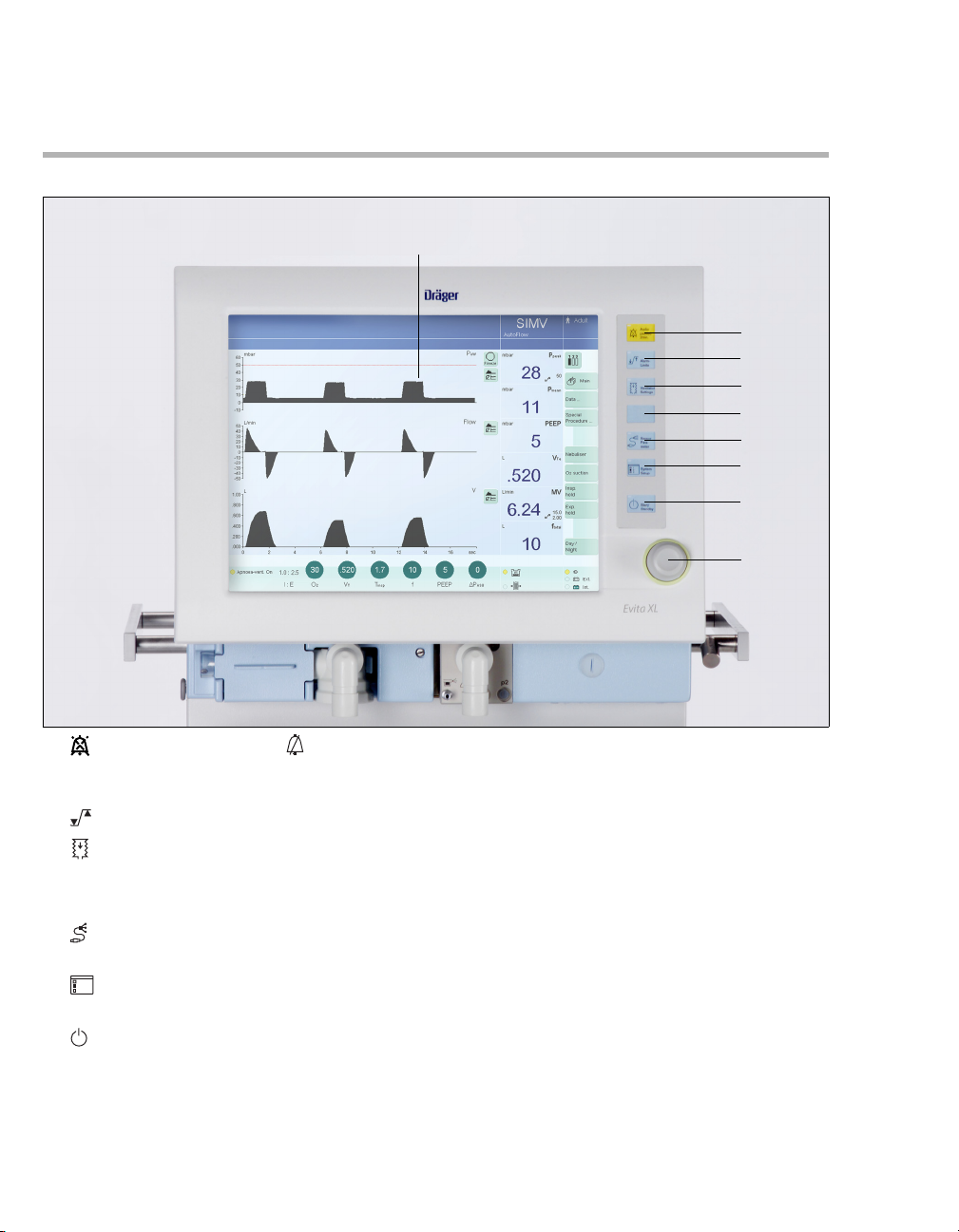
Control Panel
I
A
B
C
D
E
F
G
H
A Audio paused 2 min. or Alarm Silence
key for suppressing the alarm tone for two
minutes
B Alarm Limits key for setting alarm limits
C Ventilator Settings key for setting
ventilation mode and ventilation parameters
D Unassigned key for future functions
E Sensor Parameter key for calibrating
sensors and for switching monitoring on or off
1
2
3
F System Setup key for configuring device
functions
G Start/Standby key for switching between
operation and standby mode
H Rotary knob for selecting and confirming
settings
22
MT-0071-2008
I Touch-sensitive screen
Instructions for Use Evita XL / EvitaXLNeo SW 7.0n
Page 23
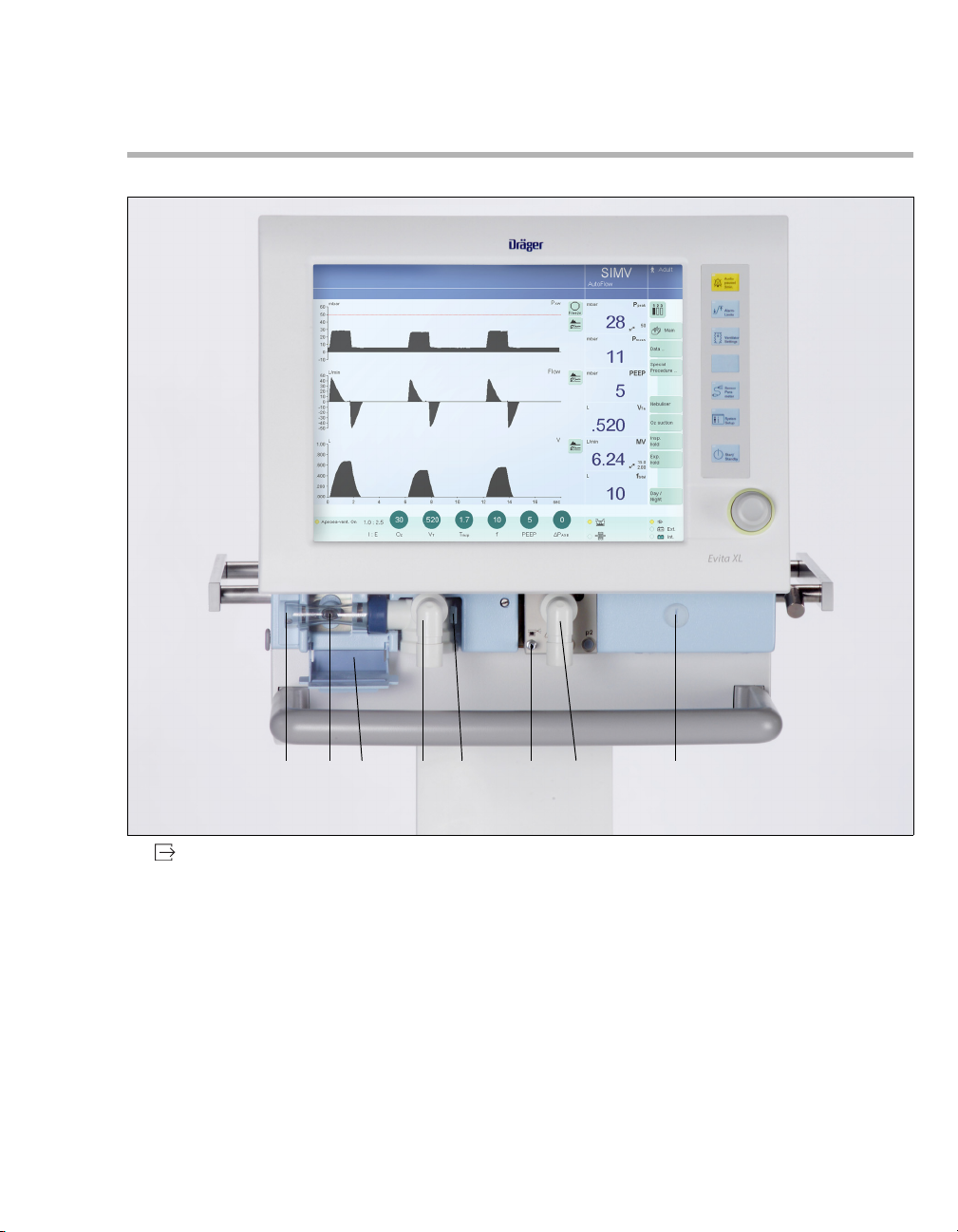
Front Connections
System Overview
B
A
A Gas exhaust port
(EXHAUST – NOT FOR SPIROMETERS)
B Flow sensor
C Flow sensor flap (thermal cover)
D Expiratory valve with expiratory connector port
(GAS RETURN)
E Latch for expiratory valve
F Nebulizer connection
G Inspiratory connector port (GAS OUTPUT)
Instructions for Use Evita XL / EvitaXLNeo SW 7.0n 23
C
D
E
FH
G
H Locking screw for protective cover
(behind it: O
2 sensor and ambient air filter)
MT-0072-2008
Page 24
System Overview
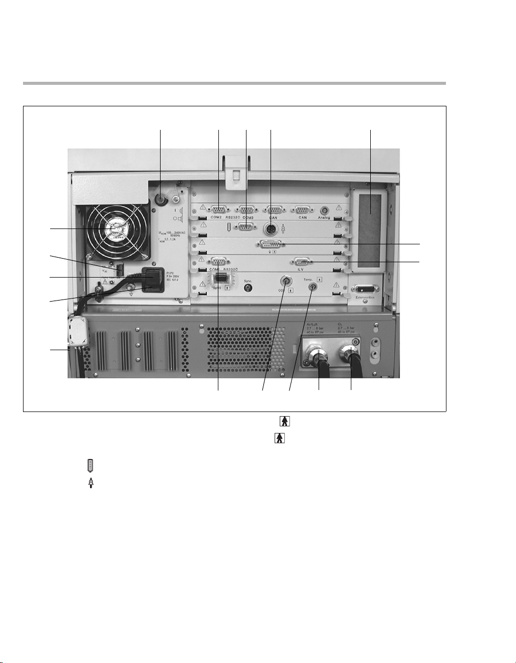
Back Panel
ABC
Q
P
O
N
M
A Power switch with protective flap
B COM 2, COM 3 ports for RS 232, 2 CAN
interfaces and analog interface (optional)
C Connection for Remote Pad (optional)
D Connection for nurse call (optional)
E Cooling-air filter
F Connection for neonatal flow sensor (optional)
G ILV socket for the connecting cable for
independent lung ventilation with two
ventilators
H Connection for O
I Connection for medical air (Air)
2
D
E
F
G
J
J Temp socket for temperature sensor
K CO
2 socket for CO2 sensor (optional)
L COM 1 RS 232C port for RS 232 interface,
e.g., for printer
M Rating plate (not visible) on the left-hand side
panel
N AC fuses
O Connector for power cable
P DC socket
Q Fan
IHKL
EvitaXL_back_panel
24
Instructions for Use Evita XL / EvitaXLNeo SW 7.0n
Page 25
Labels
Main WARNING/CAUTION label
DANGER !
RISK OF EXPLOSION IF USED IN THE
PRESENCE OF FLAMMABLE ANESTHETICS
WARNING !
DISCONNECT SUPPLY BEFORE SERVICING
REPAIRS ON THIS EQUIPMENT TO BE
PERFORMED ONLY BY DrägerService OR ITS
AUTHORIZED SERVICE CENTERS
CAUTION !
TO MAINTAIN GROUNDING INTEGRITY,
CONNECT ONLY TO A "HOSPITAL GRADE"
RECEPTACLE
TO REDUCE RISK OF ELECTRIC SHOCK, DO
NOT REMOVE COVER
USE ONLY DRY AND CLEAN COMPRESSED
AIR AND OXYGEN. WATER IN GAS SUPPLY
CAN CAUSE EQUIPMENT MALFUNCTION
FEDERAL (USA) LAW RESTRICTS THIS
DEVICE TO SALE BY OR ON THE ORDER OF A
PHYSICIAN
System Overview
No pushing
Air intake CAUTION label
CAUTION !
DO NOT BLOCK
AIR INTAKE
Instructions for Use Evita XL / EvitaXLNeo SW 7.0n 25
Page 26
System Overview
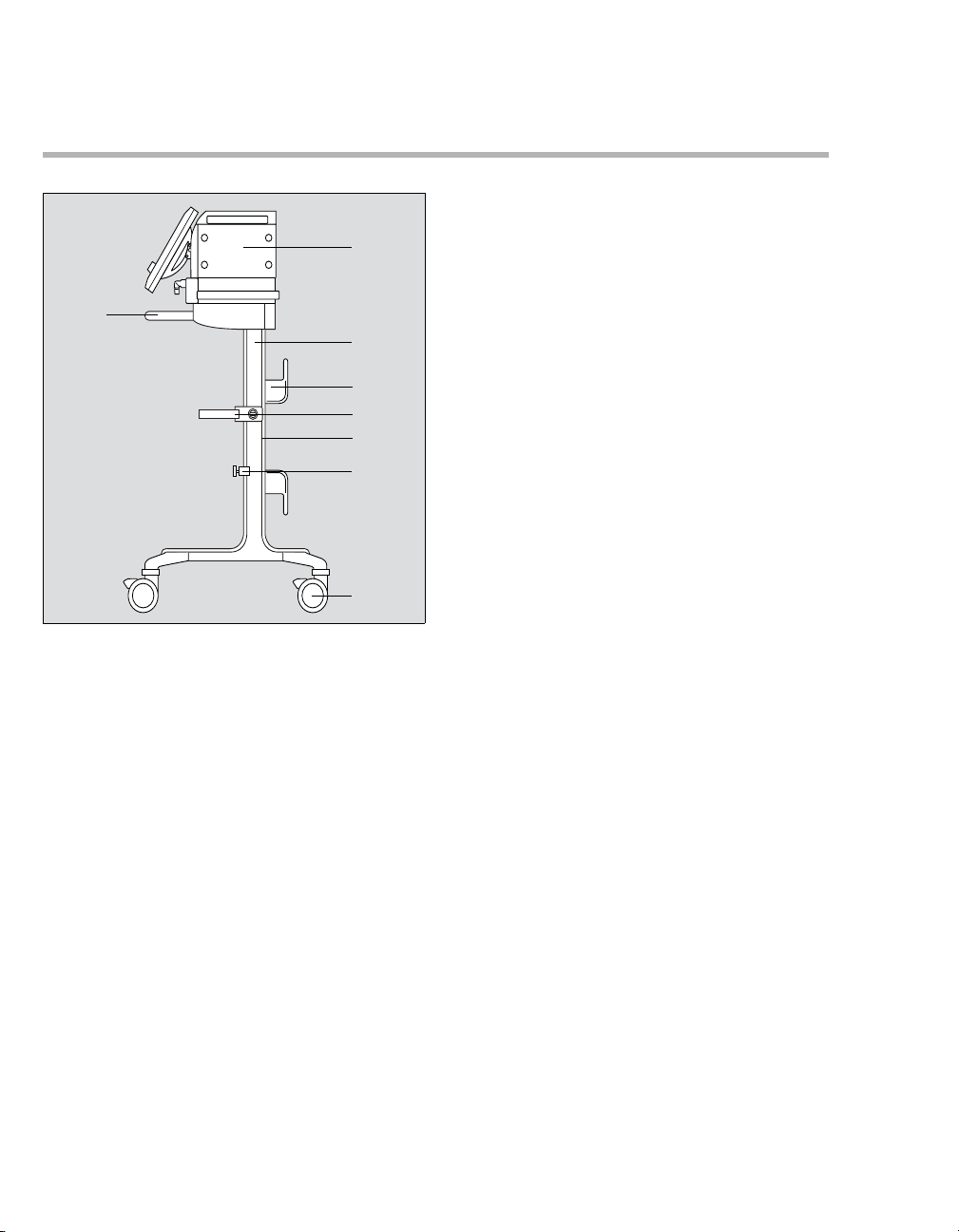
Evita XL Mobil trolley
B
A
C
D
E
F
G
H
A Evita XL
B Handle
C Trolley column
D Hose hook
E Humidifier holder (optional)
F Alignment aid
G Universal bracket with standard rail (optional)
H Dual castors with locking brakes, 4 x
123
26
Instructions for Use Evita XL / EvitaXLNeo SW 7.0n
Page 27

System Overview
Abbreviations
Abbreviation Description
Adult Option for EvitaXLNeo so that the device can be used for adults
Alarm Info Display alarm causes and remedies
Alarm Reset Acknowledge alarm message
APRV Airway Pressure Release Ventilation. Spontaneous breathing at continuous positive
airway pressure with short-term pressure release
ATC Automatic Tube Compensation
AutoFlow Special function for automatic regulation of the inspiratory flow during volume-controlled
ventilation, enables free deep breathing
BIPAP Assist
(PCV+ Assist)
BIPAP
(PCV+)
bpm Breaths per minute
BTPS Body Temperature, Pressure, Saturated
C Compliance
CAN Controller Area Network
CCP Critical Closing Pressure
CMV Continuous Mandatory Ventilation
CMV
Assist Trigger-assisted Continuous Mandatory Ventilation
CO
2 CO2 production [L/min]
Comp. Degree of tube compensation (set value)
COPD Chronic Obstructive Pulmonary Disease
CPAP Continuous Positive Airway Pressure. Spontaneous breathing with positive airway
CPAP/ PSupp Spontaneous breathing with positive airway pressure and pressure support
CPPV Continuous Positive Pressure Ventilation
C
stat Static compliance
Δint.PEEP Intermittent Positive End-Expiratory Pressure (expiratory sigh)
ΔP
Apnea Set value for PApnea relative to PEEP
ΔP
AW Pressure support on the tube
ΔPSupp Set value for P
EIP End-inspiratory pressure
Biphasic Positive Airway Pressure Assisted. Ventilation mode for assisted ventilation
with continuous positive airway pressure with two different pressure levels
Biphasic Positive Airway Pressure. Ventilation mode for spontaneous breathing at
continuous positive airway pressure with two different pressure levels
Measured values based on the conditions of the patient lungs: body temperature 37 °C
(98.6 °F), water-vapor saturated gas, ambient pressure
Intermittent ventilation with positive pressure
pressure
Controlled ventilation with continuous positive airway pressure
Supp. relative to PEEP
Instructions for Use Evita XL / EvitaXLNeo SW 7.0n 27
Page 28

System Overview
Abbreviation Description
EMC Electromagnetic compatibility
etCO
2 End-expiratory CO2 concentration
Ext. Flow External Flow
f Respiratory rate in bpm
Fail to cycle Breathing cycle failure. Ventilator detects no inspiration
f
Apnea Respiratory rate setting for apnea ventilation
FeCO
2 Expiratory CO2 concentration
FiO
2 Inspiratory O2 concentration
Flow Set value of the maximum inspiratory flow
In the Neonatal patient category:
Displayed real-time waveform, patient flow, with leakage correction (measured value)
FlowAssist Adjustable pressure assistance in proportion to patient flow
Flow
bf Basic flow (system setting), see "Power Characteristics" on page 213
Flow
exp Expiratory flow, without leakage correction
Flowinsp Inspiratory flow, without leakage correction
Flow
leak Current leakage flow
Flow
out Flow through the expiratory valve during inspiration
Flowpatient Inspiratory/expiratory flow, with leakage correction (measured value)
f
mand Mandatory mechanical portion of overall respiratory rate
f
spn Spontaneous breathing portion of overall respiratory rate
ftotal Total respiratory rate (fmand + fspn)
f
trig. Triggered portion of overall respiratory rate
I : E Ratio of inspiratory : expiratory time
IBW Ideal Body Weight
ID ∅ Internal tube diameter (set value)
ILV Independent Lung Ventilation
Ventilation with two ventilators, one for each lung
insp. flow Inspiratory Flow
IPPV Intermittent Positive Pressure Ventilation
Intermittent ventilation with positive pressure
IPPV
Assist Trigger-assisted Intermittent Positive Pressure Ventilation
IRV Inversed Ratio Ventilation. Ventilation with inversed ratio of inspiration/expiration
KG Body weight [kg]
K
Tube Tube coefficient
LIP Lower Inflection Point
LUST List-controlled universal interface driver program
MEDIBUS Dräger communication protocol for medical devices
28
Instructions for Use Evita XL / EvitaXLNeo SW 7.0n
Page 29

System Overview
Abbreviation Description
MMV Mandatory Minute (Volume) Ventilation
MV Minute volume, without leakage correction (measured value)
MVleak Leakage minute volume – mean leakage flow, averaged over inspiration and expiration
(measured value)
MV
Patient Expiratory measured minute volume, with leakage correction
MVspn Spontaneously breathed minute volume
NeoFlow Option for Evita XL so that the device can be used for neonates
NIF Negative Inspiratory Force. Maximum inspiratory effort
NIV Non-Invasive Ventilation, mask ventilation
NTC Negative Temperature Coefficient
NTPD Normal Temperature, Pressure, Dry
O
2 Set value for inspiratory O2 concentration [Vol.%]
O
2↑ suction Oxygenation program active
P0.1 100 ms occlusion pressure
P
Apnea Set value for inspiratory pressure with apnea ventilation
P
AW Airway pressure at the Y-piece (measured value)
PCV+ Assist
(BIPAP Assist)
PCV+
(BIPAP)
Ventilation mode for assisted ventilation with continuous positive airway pressure with
two different pressure levels
Ventilation mode for spontaneous breathing at continuous positive airway pressure with
two different pressure levels
PEEP Positive End-Expiratory Pressure
PEEP
i Intrinsic PEEP
P
exp Airway pressure in the expiratory breathing hose
high Set value of the upper pressure level in APRV
P
P
insp Set value of the upper pressure level in PCV+
Pleth Plethysmogram
P
limit Set value of maximum applied airway pressure during measuring maneuver Low Flow
PV-Loop
P
low Set value for the lower pressure level in APRV
PLV Pressure Limited Ventilation
P
max Maximum airway pressure
PMC Point of Maximum Curvature
P
mean Mean airway pressure at the Y-piece (measured value)
P
min Minimum airway pressure
Ppeak Peak pressure
P
plat End-inspiratory airway pressure
PS Pressure Support
Instructions for Use Evita XL / EvitaXLNeo SW 7.0n 29
Page 30

System Overview
Abbreviation Description
Pstart Initial airway pressure during measuring maneuver Low Flow PV-Loop
PSupp. Pressure-supported spontaneous breathing
P
Supp. Set value for PSupp. pressure support
PSV Pressure-supported spontaneous breathing
P
Trach Pressure in the trachea
QRS Intraventricular excitation propagation in the ECG
RResistance
RecrTrend Recruitment Trend. Breath-based trend
R
exp Flow resistance of the expiratory breathing hose
R
insp Flow resistance of the inspiratory breathing hose
RSBi Rapid Shallow Breathing. Quotient of spontaneous breathing rate and tidal volume
SB Spontaneous Breathing. Spontaneous breath at ambient pressure
SIMV Synchronized Intermittent Mandatory Ventilation
Slope Pressure rise time for PSupp.
SpO
2 Functional oxygen saturation
T Inspiratory breathing gas temperature
T
Apnea Apnea alarm delay time
Ta ue Respiratory time constant, expiratory:
– with activated leakage compensation = leakage-compensated tidal volume /
leakage-compensated maximum expiratory flow
– with deactivated leakage compensation = expiratory tidal volume / maximum
expiratory flow
Tdeconnect Delay time for alarm limit PAW (airway pressure low) in Mask (NIV) application mode
e Expiratory time
T
TGI Tracheal Gas Insufflation
T
high Time for the upper pressure level in APRV
Ti Inspiratory time
T
i max Set value of the inspiratory time with non-invasive ventilation in CPAP/ PSupp
ventilation mode
insp Set value of the inspiratory time
T
T
low Time for the lower pressure level in APRV
Tmax [sec] Maximum period of measuring maneuver Low Flow PV-Loop
Trigg. [L/min] Set value for the flow trigger threshold
UIP Upper Inflection Point
UMDNS Universal Medical Device Nomenclature System
V
ds Serial dead space
V
limit Set value of maximum applied volume during measuring maneuver Low Flow PV-Loop
Vol .Assist Adjustable pressure support in proportion to tidal volume
30
Instructions for Use Evita XL / EvitaXLNeo SW 7.0n
Page 31

System Overview
Abbreviation Description
T Set value for tidal volume
V
VT
PSupp Inspiratory tidal volume during a PSupp. breath
VTApnea Set value for tidal volume of apnea ventilation
V
Te Expiratory tidal volume
V
Ti Inspiratory tidal volume
Vtrap Volume trapped in the lung by Intrinsic PEEP and not exhaled during subsequent
expiration
Instructions for Use Evita XL / EvitaXLNeo SW 7.0n 31
Page 32

System Overview
Symbols
Symbol Name Description
Audio paused 2 min. Suppress audible alarm for 2 minutes
Alarm Silence Suppress audible alarm for 2 minutes
Alarm Limits Set alarm limits
Ventilator Settings Settings for ventilation
Sensor Parameter Sensor calibration
1
2
3
123
123 123
System Setup Configuration
Start/Standby Ventilation/standby
Main Back to main screen
Select different sets of measured values
Freeze Freeze
Display alarm limit in trend
Real-time waveforms, loops, and trends
Lower alarm limit
Upper alarm limit
Nebulizer active
Mask (NIV) Non-Invasive Ventilation. Mask ventilation
Active Humid. Breathing gas humidifier
HME/ Filter Heat and Moisture Exchanger
Mains supply
Ext. External battery
Int. Internal batteries
Insert flow sensor
Direct access to settings, locked
Direct access to settings, unlocked
Exp. Expiratory outlet port (GAS RETURN)
Insp. Inspiratory port (GAS OUTPUT)
1)
Gas exhaust port (EXHAUST – NOT FOR SPIROMETER)
32
Instructions for Use Evita XL / EvitaXLNeo SW 7.0n
1)
Page 33

Symbol Name Description
m
Adult Adult patient category
Ped. Pediatric patient category
Neo. Neonatal patient category
Supplementary information
X Close dialog window
Mark for a correct result during Device Check
Caution! Observe important safety-relevant information and
precautionary measures in the Instructions for Use.
Consult Instructions for Use!
Protective grounding
Protection class type B
Protection class type BF
Spontaneous breathing activity by the patient
Remote Pad, remote control
Nurse Call
System Overview
Tube compensation activated
Select screen configuration
Save screen configuration
Mask out screen configuration
Country Country-specific settings
Do not reprocess
ESD warning symbol
Disposal information
8415824
.
x
a
m
g
k
0
5
/
g
k
0
4
g
k
0
5
.
x
a
m
max. 5°
g
k
0
5
.
x
a
m
Caution! Consult
accompanying
g
k
documents!
0
1
.
x
a
g
k
0
6
.
x
a
m
max. 100 kg
max. 5°
Counter weight 8415824 in EvitaMobil trolley
Requirements to avoid Evita XL with the EvitaMobil trolley tipping
over
Requirements to avoid Evita XL with the Evita XL Mobil trolley
tipping over
Label to identify surfaces on the device where there is an increased
risk of the device tipping over when pressing, leaning against, etc.
1) additionally, depending on ventilator hardware version
Instructions for Use Evita XL / EvitaXLNeo SW 7.0n 33
Page 34

This page has intentionally been left blank.
34 Instructions for Use Evita XL / EvitaXLNeo SW 7.0n
Page 35

Operating Concept
Control Panel . . . . . . . . . . . . . . . . . . . . . . . . . 36
Buttons with a Fixed Function . . . . . . . . . . . 36
Screen . . . . . . . . . . . . . . . . . . . . . . . . . . . . . . . 37
Main . . . . . . . . . . . . . . . . . . . . . . . . . . . . . . . . . 37
Main menu bar . . . . . . . . . . . . . . . . . . . . . . . . . 37
Dialog windows. . . . . . . . . . . . . . . . . . . . . . . . . 38
Therapy bar . . . . . . . . . . . . . . . . . . . . . . . . . . . 38
Therapy controls. . . . . . . . . . . . . . . . . . . . . . . . 38
Controls and color scheme. . . . . . . . . . . . . . . . 39
Setting ventilation parameters on the main
screen. . . . . . . . . . . . . . . . . . . . . . . . . . . . . . . . 40
Direct setting of ventilation parameters . . . . . . 40
Linked setting of ventilation parameters . . . . . . 41
Direct and linked setting of ventilation
parameters . . . . . . . . . . . . . . . . . . . . . . . . . . . . 41
Operating Concept
Instructions for Use Evita XL / EvitaXLNeo SW 7.0n 35
Page 36

Operating Concept
Control Panel
The control panel is characterized by the small
number of operating elements, its clear layout and
easy operation.
Its main elements are:
D
Evita XL
B
C
A
Buttons with a Fixed Function
A Large screen with all the information and
controls needed for ventilation.
B Fixed function keys beside the screen – for
rapid access to major functions.
C Rotary knob for selecting and confirming
settings on the screen.
001
The following buttons are available for rapid access
to important screen functions:
D
A
B
C
D
E
F
G
Evita XL
36
A Audio paused 2 min. or Alarm Silence
key for suppressing the alarm tone for two
minutes
B Alarm Limits for setting the alarm limits.
C Ventilator Settings for setting the
ventilation mode and ventilation parameters
D Unassigned key for future functions
E Sensor Parameter for calibrating the
sensors and for switching monitoring on or off
1
2
3
F System Setup for configuring the device
functions
G Start/Standby for selecting the operating
mode or standby mode
002
Instructions for Use Evita XL / EvitaXLNeo SW 7.0n
Page 37

Screen
Operating Concept
Main
The Main screen displays all the most important
ventilation data at a glance.
A
B
D
A Header bar with the following fields:
– Alarms, messages, and instructions for the
user, see page 124
– Therapy status: Therapy type (ventilation
or O
2 Therapy), ventilation mode, and
additional settings
– Patient category, see page 79
B Monitoring area with waveforms, loops, trends,
and measured values, see "Measured Values,
Graphics, and Trends" on page 129. The
display can be configured, see "Selecting
screen display" on page 157.
C Main menu bar with buttons for opening dialog
windows and activating functions, see page 37.
D Therapy bar with therapy controls for the
ventilation parameters of the active ventilation
mode and its additional settings, see page 38.
E Field for device status with type of
humidification
F Power supply display
E
C
F
Main menu bar
The main menu bar contains fixed and freely
configurable buttons. Touching a button opens the
corresponding dialog window or activates the
corresponding function.
Fixed buttons
123 123
123
, , for selecting a different set of measured
values in the field for measured values.
Main for selecting the main screen.
Data ... for displaying all measured values, the
logbook, or trends on an additional card.
Special Procedure ... for selecting additional
functions, e.g., medication nebulization or
500
oxygenation for bronchial suctioning.
Freely configurable buttons
Additional buttons for directly accessing functions
or dialog windows can be configured, See "Defining
additional buttons in the main menu bar"
on page 158.
Instructions for Use Evita XL / EvitaXLNeo SW 7.0n 37
Page 38

Operating Concept
Dialog windows
Dialog windows consist of one or several pages
which are displayed by touching the corresponding
horizontal or vertical tab. Dialog windows contain
elements for operating the device and inform the
user of current settings. Dialog windows can be
opened by pressing a key or by touching a button in
the main menu bar.
A
B
E
D
B
C
A Dialog window title
B Tab – touch the relevant tab to open a page.
C Setting assistance field
D Button for accessing additional information
(if applicable)
E Button for closing the dialog window
Therapy controls
The therapy controls are used to set the ventilation
parameters.
Therapy controls are contained in the therapy bar
of the active ventilation mode and in the dialog
window for specifying the ventilation settings.
A
A Therapy controls
502
Start-up settings
Arrows ( ) beside the scales on the therapy
controls indicate the start-up values valid when
Evita XL is switched on. These values can be
configured as required by the hospital. See "Setting
start-up values for ventilation" on page 163.
502
Therapy bar
The therapy bar on the main screen contains the
therapy controls for the active ventilation mode.
F
F Therapy controls
38
Locking
The therapy controls in the therapy bar can be
locked against the ventilation parameters being
changed by accident. See "Locking therapy
controls" on page 160.
501
Instructions for Use Evita XL / EvitaXLNeo SW 7.0n
Page 39

Operating Concept
Controls and color scheme
The following controls are available to the user:
–Tabs
– Therapy controls
– Buttons
The touch-sensitive screen controls are used in a
similar way as real keys and rotary knobs:
– Touching these controls with a fingertip is
equivalent to pressing a key or taking hold of a
knob.
– Settings are made and confirmed by turning
and pressing the rotary knob.
Colors are used to indicate the status of the screen
controls:
gray = not available
yellow = ready for use
pale green = available, but is not active
dark green = available and is active
For buttons:
1
2
4
3
1 to select = touch,
2 the button turns yellow,
3 to confirm = press rotary knob,
4 the button turns pale green or dark green.
For therapy controls:
1
2
5
3
4
1 to select = touch,
2 the therapy control turns yellow,
3 to set = turn rotary knob,
4 to confirm = press rotary knob,
5 the therapy control turns pale green or dark
green.
Exceeding the limit set for a ventilation
parameter
When the limit set for the parameter has been
reached, Evita XL displays a message.
z To exceed the set limit, press the rotary knob.
The user can now exceed the set limit.
If the maximum limit set for a parameter has been
reached, e. g., in relation to other parameters, it is
not possible to exceed the set limit.
z Press rotary knob. Evita XL adopts the
maximum value that can be set.
004
005
Instructions for Use Evita XL / EvitaXLNeo SW 7.0n 39
Page 40

Operating Concept
Setting ventilation parameters on the
main screen
On the main screen in the therapy bar:
1 Touch the therapy control.
Evita XL opens the Ventilator Settings dialog
window. The selected therapy control (A) is yellow
and can be directly set.
A
2 To set the value, turn the rotary knob.
3 Press the rotary knob to confirm the value.
The color of the therapy control changes to dark
green. The new setting is now effective.
Direct setting of ventilation parameters
When a ventilation parameter is set directly, the
changes to a setting are immediately effective. The
user can see the effect of the modified setting on
the patient at once. The finally chosen setting does
not have to be confirmed again.
The following ventilation parameters can be set
directly:
– PEEP in all ventilation modes
– P
insp in PCV+ and PCV+ Assist
– P
high and Plow in APRV
Direct setting can be performed in the Ventilator
Settings dialog window.
O
2 cannot be set directly.
Setting ventilation parameters directly
1 Touch the relevant therapy control.
2 Press the rotary knob and hold down for approx.
3 seconds.
The therapy control turns dark green with a yellow
edge. The direct setting function is now active.
3 To set a value, press and turn the rotary knob.
503
The set value is immediately effective.
After releasing the rotary knob, the parameter can
still be set directly:
z Press and turn the rotary knob again.
Exceeding the limit set for a parameter with
direct setting
When the limit set for the parameter has been
reached, Evita XL displays a message.
4 Briefly release the rotary knob.
5 Press and turn the rotary knob again.
The user can now exceed the set limit.
504
40
Instructions for Use Evita XL / EvitaXLNeo SW 7.0n
Page 41

Operating Concept
Linked setting of ventilation parameters
Linked setting is possible for the following
parameters:
– P
insp/PEEP
The pressure difference remains constant.
– P
high/Plow
The pressure difference remains constant.
– T
insp/f
The I:E ratio remains constant.
Linking P
insp/PEEP
D
C
A
1 Touch the Pinsp (A) or PEEP (B) therapy
control. The color changes to yellow.
2 Touch the Link Pinsp/PEEP button (C).
The therapy control of the other parameter (P
PEEP) turns yellow.
3 Turn the rotary knob to set the value for P
PEEP. The linked value is set correspondingly.
4 Press the rotary knob to confirm the value.
Both therapy controls turn dark green.
The linked setting of T
in the same way.
z Touch the I : E constant button (D).
The linked setting of P
APRV and can be performed in the same way.
B
insp or
insp or
insp and f can be performed
high and Plow is possible in
Direct and linked setting of ventilation
parameters
Direct and linked setting is possible for Pinsp/PEEP
and for Phigh/Plow.
Linking and directly setting Pinsp/PEEP
G
F
E
1 Touch the Pinsp (E) or PEEP therapy control
(F).
2 Touch the Link P
3 Press the rotary knob and hold down for approx.
3 seconds.
505
The therapy controls turn dark green with a yellow
edge. The direct setting function is now active.
4 To set a value, press and turn the rotary knob.
The linked value is set correspondingly. The values
are immediately effective.
After releasing the rotary knob, the parameters can
still be set directly:
z Press and turn the rotary knob again.
Exceeding the limit set for a parameter with
direct setting
When the limit set for a parameter has been
reached, Evita XL displays a message.
5 Briefly release the rotary knob.
6 Press and turn the rotary knob again.
The user can now exceed the set limit.
Direct and linked setting of P
possible in APRV and can be performed in the
same way.
insp/PEEP button (G).
high and Plow is
506
Instructions for Use Evita XL / EvitaXLNeo SW 7.0n 41
Page 42

This page has intentionally been left blank.
42 Instructions for Use Evita XL / EvitaXLNeo SW 7.0n
Page 43

Preparation
Safety Information for Preparation . . . . . . . . 44
Safety Information for the Trolley . . . . . . . . . 44
Preparation of the Evita XL Mobil Trolley. . . 45
Attaching universal bracket with standard
rail to trolley . . . . . . . . . . . . . . . . . . . . . . . . . . . 46
Attaching humidifier holder to trolley . . . . . . . . 46
Attach the accessory to the standard rail . . . . . 46
Attaching compressed gas cylinders to
trolley . . . . . . . . . . . . . . . . . . . . . . . . . . . . . . . . 47
Placing the device . . . . . . . . . . . . . . . . . . . . . . 48
Preparation of the EvitaMobil Trolley . . . . . . 49
Placing the device . . . . . . . . . . . . . . . . . . . . . . 50
Positioning the Control Panel . . . . . . . . . . . . 51
Mounting the control panel to the device . . . . . 51
Mounting the control panel to a wall rail . . . . . . 51
Preparation
Preparation of Evita XL for Ventilation . . . . . 52
Installing the expiratory valve . . . . . . . . . . . . . . 52
Mounting the flow sensor . . . . . . . . . . . . . . . . . 52
Flow sensor flap (thermal cover) . . . . . . . . . . . 53
Installing an O
Safety information on using HMEs, bacterial
filters, and breathing circuits. . . . . . . . . . . . . . . 54
Connecting a breathing gas humidifier . . . . . . . 55
Connecting breathing circuit. . . . . . . . . . . . . . . 56
Installing a temperature sensor . . . . . . . . . . . . 57
Installing a neonatal flow sensor . . . . . . . . . . . 58
Installing a CO
Connecting to the power supply . . . . . . . . . . . . 60
Connecting to the gas supply . . . . . . . . . . . . . . 61
Connecting Evita Remote . . . . . . . . . . . . . . . 62
Connecting Nurse Call . . . . . . . . . . . . . . . . . . 63
Transportation within the hospital /
Moving Evita XL with the trolley . . . . . . . . . . 65
Instructions for Use Evita XL / EvitaXLNeo SW 7.0n 43
2 sensor capsule . . . . . . . . . . . . 53
2 cuvette and CO2 sensor . . . . . 59
Page 44

Preparation
Safety Information for Preparation
WARNING
Before each use, reprocess the device and all
the accessories according to the information
in the Instructions for Use, see page 189.
Hospital infection control regulations must be
observed!
WARNING
To prevent the ventilator from tipping over, it
must not be tilted more than 5°! Otherwise,
high risk of the ventilator tipping over.
Safety Information for the Trolley
WARNING
In the event of non-observance of the
permitted loads and centers of gravity, there is
a high risk of the ventilator tipping over.
Observe the maximum loads and centers of
gravity.
CAUTION
Do not use the trolley in the event of visible
damage e. g., damaged castors! Call
DrägerService.
WARNI NG
Do not place any container with liquids
(e.g., infusion bottle) above or on top of
Evita XL. Any liquid getting into the device
could prevent Evita XL from working properly
or damage it and endanger the patient.
CAUTION
Lock all the castors and check correct operation
of the brakes when parking the trolley.
CAUTION
Attach devices securely to the trolley. Check to
make sure they are secure. Risk of damage to the
device or personal injury!
CAUTION
Do not lean or press against surfaces identified by
the label The trolley may tip over.
44
Instructions for Use Evita XL / EvitaXLNeo SW 7.0n
Page 45

Preparation of the Evita XL Mobil Trolley
Preparation
The necessary accessories are to be installed by
properly trained service personnel in accordance
with the respective mounting instructions:
– Humidifier holder
– Universal bracket
– External battery
– Breathing air compressor
– Cylinder holders for compressed gas cylinders
Requirements to avoid Evita XL with the
Evita XL Mobil trolley tipping over:
max. 50 kg
max. 10 kg
max. 60 kg
WARNING
Do not move the Evita XL Mobil trolley with
Evita XL any faster than normal walking pace.
There is a higher risk of it tipping over at
thresholds, on uneven floors, and on ramps.
Reduce speed.
WARNING
– Do not load the base plate of the
Evita XL Mobil trolley with more than 60 kg
(132 lbs) (e.g., with compressed gas
cylinders, breathing air compressor,
external battery).
– Do not load the console of the
Evita XL Mobil trolley with more than 50 kg
(110 lbs). E.g., through:
– device,
– patient monitor with monitor holder and
– hinged arm.
– Do not load the humidifier holder (optional)
or universal bracket (optional) with more
than 10 kg (22 lbs), e.g., with breathing gas
humidifier or medication nebulizer.
High risk for the ventilator to tip over and to
injure the patient.
WARNING
The maximum total load for the trolley is
100 kg (220 lbs). Otherwise there is a higher
risk of it tipping over.
max. 100 kg
max. 5°
125
WARNING
To prevent the ventilator from tipping over, it
must not be tilted more than 5°! Otherwise,
high risk of the ventilator tipping over.
Instructions for Use Evita XL / EvitaXLNeo SW 7.0n 45
Page 46

Preparation
Attaching universal bracket with
standard rail to trolley
The universal bracket with standard rail (optional) is
attached to the trolley.
A
C
1 Fully unscrew clamping screw (A).
2 Engage right-hand side of the bracket at the
right-hand side of the rail (B). Ensure that the
nose of the universal bracket is located
completely behind the alignment aid.
3 Align the bracket (C) horizontally and press the
left-hand side of the bracket against the lefthand side of the column.
4 Tighten the clamping screw (A). Ensure that the
nose of the universal bracket is located
completely behind the alignment aid.
5 Check that the universal bracket is securely in
place.
B
Attaching humidifier holder to trolley
The humidifier holder (optional) can be attached to
the left- or right-hand side of the trolley column.
Attachment of the humidifier holder to the righthand side is shown here.
1 Turn the clamping screw (A) counterclockwise
until the humidifier holder can be inserted in the
groove of the trolley column (B).
B
A
120
2 Turn the clamping screw (A) clockwise until the
3 Move the standard rail (C) to the required
Attach the accessory to the standard rail
Fasten accessory, e.g., breathing gas humidifier or
medication nebulizer, to the standard rail. Observe
maximum load!
C
humidifier holder is firmly engaged in the
groove.
position.
121
Adjusting height of universal bracket
1 Unscrew the clamping screw (A).
2 Adjust the height of the universal bracket (C).
3 Align the universal bracket horizontally.
4 Tighten the clamping screw (A) again.
46
Instructions for Use Evita XL / EvitaXLNeo SW 7.0n
Page 47

Preparation
Attaching compressed gas cylinders to
trolley
Only available with cylinder holder option
WARNING
Attach compressed gas cylinders securely to
the trolley with the two Velcro straps.
Otherwise, tilt stability is not assured.
WARNING
Have the height of the upper holder adapted to
the height of the relevant compressed gas
cylinders by properly trained service
personnel. Adjust the height so that the upper
halves of the compressed gas cylinders are
held by the Velcro straps. Otherwise, tilt
stability may be compromised.
WARNING
The length of the Velcro straps must be
appropriate for the diameter of the
compressed gas cylinders in order to ensure
correct fastening. If necessary, have
appropriate Velcro straps fitted by authorized
technical service personnel. Otherwise,
secure fastening is not assured.
Compressed gas cylinders with the following
dimensions can be fitted:
Diameter: 80 to 160 mm (3.15 to 6.3 inch)
Length: 420 to 870 mm (16.54 to 34.25 inch)
1 Place the cylinders in the mounts on the trolley.
2 Secure each cylinder with two Velcro straps (A).
A
A
CAUTION
Position compressed gas cylinders with pressure
reducers in such a way that the pressure reducers
may not be damaged during transport. The base
plate of the trolley serves as impact protection. If
the compressed air cylinders are too big,
particular care must be taken.
A
A
122
CAUTION
Not every combination of diameter and length can
be fitted.
The compressed gas cylinders with mounted
pressure reducers must not touch the console of
the trolley.
The max. diameter allowed is 178 mm (7.0 inch),
if the foot of the compressed gas cylinder
completely is seated solidly on the base plate of
the lower holder or is formed as a hemisphere.
Instructions for Use Evita XL / EvitaXLNeo SW 7.0n 47
Page 48

Preparation
Placing the device
z Place device on the console and lock it in place,
you should hear the snap of the latching device.
The device must be firmly fixed on both sides of
the trolley.
124
48
Instructions for Use Evita XL / EvitaXLNeo SW 7.0n
Page 49

Preparation of the EvitaMobil Trolley
Preparation
The necessary accessories are to be installed by
properly trained service personnel in accordance
with the respective mounting instructions:
– Humidifier holder
– External battery
– DC connecting cable
– Breathing air compressor
– Cylinder holders for compressed gas cylinders
– Monitor holder with counter weight kit
WARNING
Monitors with monitor holders should only be
installed on Evita XL when the EvitaMobil
trolley is equipped with a counter weight
mounted under the base plate or when a
breathing air compressor is mounted. High
risk of the ventilator tipping over!
If EvitaMobil is equipped with the counter weight,
there is a label (part no. 8415824) on the front side
of the base plate.
8415824
Requirements to avoid Evita XL with the
EvitaMobil trolley tipping over:
max.
40 kg / 50 kg
max. 50 kg
max. 5°
WARNING
To prevent the ventilator from tipping over, it
must not be tilted more than 5°! Otherwise,
high risk of the ventilator tipping over.
007
WARNING
Do not move the EvitaMobil trolley with
Evita XL any faster than normal walking pace.
006
There is a higher risk of it tipping over at
thresholds, on uneven floors, and on ramps.
Reduce speed.
Instructions for Use Evita XL / EvitaXLNeo SW 7.0n 49
Page 50

Preparation
WARNING
– Do not load the base plate of the EvitaMobil
trolley with more than 50 kg (110 lbs)
(e.g., with compressed gas cylinders,
breathing air compressor).
– Do not load the console of the EvitaMobil
trolley with more than 40 kg (88 lbs)
(e.g., with the device and hinged arm).
– When a monitor holder is fitted to Evita XL
and a counter weight is mounted under the
EvitaMobil trolley base plate or a breathing
air compressor is mounted, the console of
the EvitaMobil trolley may be loaded with
up to 50 kg (110 lbs) (e.g., with the device,
patient monitor, and hinged arm).
– Do not fix more than one breathing gas
humidifier on the humidifier holder
(optional).
High risk for the ventilator to tip over and to
injure the patient.
Placing the device
008
z Place device on the console and lock it in place,
you should hear the snap of the latching device.
The device must be firmly fixed on both sides of
the trolley.
z Depending on the number of cylinder holders
fitted, a maximum of 4 compressed gas
cylinders can be placed on the holders and
secured with Velcro straps.
z Attach the breathing gas humidifier to the
humidifier holder (optional). Observe the
breathing gas humidifier’s Instructions for Use.
50
Instructions for Use Evita XL / EvitaXLNeo SW 7.0n
Page 51

Positioning the Control Panel
Preparation
CAUTION
Do not place control panel upright or lean against
any objects, do not lay it on its front. Physical
damage to the control panel is likely. When
changing the control panel, lay it on its back.
Mounting the control panel to the device
z Hang control panel into its mounts on Evita XL
until it clicks into position.
A
Tilting the control panel:
z Press segments (A) on the right and left and, at
the same time, tilt control panel to the desired
position.
Mounting the control panel to a wall rail
A
1 Press segments (A) on the right and left, and tilt
control panel fully downwards.
009
2 Hold down release buttons (B) on the left and
right and lift control panel from its mounts on
Evita XL.
3 Uncoil the cable as far as necessary.
4 Mount the control panel to the wall rail.
B
010
011
Instructions for Use Evita XL / EvitaXLNeo SW 7.0n 51
Page 52

Preparation
C
012
5 To lock the control panel in place, pull down the
latch (located beneath the bracket (C)) and turn
it in the direction of the wall rail.
Preparation of Evita XL for Ventilation
NOTE
The control panel rail clamps are designed for use
with 25 mm x 10 mm wall rails.
Installing the expiratory valve
A
B
1 Press down the segments on the right and left
and tilt the control panel (A) upwards.
2 Push expiratory valve (B) into the mount until it
clicks into position. Check that it is properly
engaged by gently pulling on the port.
Mounting the flow sensor
A
1 Push connector socket (A) all the way to the left.
013
B
2 Place flow sensor (B) into its mount – with the
connector facing towards the device – and push
into the socket, as far as it will go.
3 Push flow sensor to the right and into the rubber
lip seal of the expiratory valve, as far as it will
go.
014
015
52
Instructions for Use Evita XL / EvitaXLNeo SW 7.0n
Page 53

Preparation
Flow sensor flap (thermal cover)
The flap helps to prevent the formation of
condensation in the flow sensor when using an
active breathing gas humidifier and when heated
expiratory hoses are connected.
Inserting the flow sensor flap
A
A
z Slightly press together the spring-loaded arms
of the flap (A) at the side and push into the
mount on the device.
NOTE
The flow sensor flap can be removed for transport
purposes.
NOTE
The flow sensor and the expiratory valve can only
be inserted or removed when the flap is open.
Keep the flap closed during ventilation.
The flap swivels downwards.
Installing an O2 sensor capsule
– When using the system for the first time
– When the display reads O
of range !!!
– When calibration can no longer be performed
1 Ensure device is placed in standby mode or is
switched off completely.
2 Press down the segments on the right and left
and tilt the control panel upwards.
016
2 measurement out
D
C
A
B
3 Turn inspiratory port (A) to the left.
4 Use coin to loosen screw and remove protective
cover (B).
5 Loosen the two knurled screws and remove lid
from the sensor housing (C).
6 Remove old sensor capsule (D) and insert new
sensor capsule.
018
Opening the flow sensor flap
z Pull the flap forwards.
Instructions for Use Evita XL / EvitaXLNeo SW 7.0n 53
NOTE
The sensor end with the circular tracks must be
visible.
7 Close the sensor housing (C) securely with the
two knurled screws.
8 Screw protective cover (B) back in place.
CAUTION
To prevent accidental blockage of air intake,
017
protective cover must always be in place for
operation.
Page 54

Preparation
9 Dispose of the used O2 sensor capsule, see
"Disposal of O2 sensor" on page 208.
WARNING
Treatment of batteries and O2 sensor
capsules:
Do not throw in fire. Risk of explosion!
Do not open using force. Risk of corrosion!
Danger of bodily injury.
Follow all local, state, and federal regulations
with respect to environmental protection
when disposing of batteries and O
2 sensor
capsules.
Safety information on using HMEs,
bacterial filters, and breathing circuits
The use of additional components in the breathing
system can significantly increase inspiratory and
expiratory breathing resistance and exceed
standard requirements. Examples: Inspiratory or
expiratory filters, HME (heat and moisture
exchanger), coaxial hoses.
Evita XL is designed to minimize the patient’s work
of breathing. Operation does not require inspiratory
or expiratory bacterial filters.
WARNING
The use of bacterial filters and HMEs therefore
requires particular care and monitoring by the
user. Especially during medication
nebulization and humidifying, the resistance
of an expiratory filter may increase gradually.
A higher breathing resistance leads to increased
work of breathing and greater trigger effort during
assisted ventilation. Under unfavorable conditions,
this can lead to an undesirable intrinsic PEEP. This
can be recognized by the fact that the expiratory
flow does not return to zero at the end of expiration.
If the PEEP is unacceptably high, this is indicated
by an alarm. The measured PEEP is then
approx. 8 mbar (8 cmH
Check and replace the bacterial filter and HME if
they are the cause of the PEEP alarm.
2O) above the set PEEP.
A breathing resistance in the patient connection
cannot be monitored directly by the ventilator. For
this reason:
z Determine inspiratory and expiratory breathing
resistance in the breathing circuit before
ventilation in standby mode by means of the
airtight check (see page 73).
z Check the condition of the patient and the
device’s measured values for volume and
resistance frequently.
z Observe the Instructions for Use for the HMEs,
filters and coaxial hose systems in use.
WARNI NG
Do not use an HME together with a medication
nebulizer or breathing gas humidifier. This
can lead to a greater breathing resistance.
WARNI NG
Dräger cannot warrant or endorse the safe
performance of heat/moisture exchangers.
The user must verify that the heat/moisture
exchanger is covered by a technical safety
certificate which guarantees complete
suitability for the intended use.
WARNI NG
The flow resistance of bacteria filters placed in
the expiratory side may be substantially
increased by nebulized aerosols with the risk
of impaired ventilation. If an expiratory filter is
used during nebulization, airway pressures
and flow should be monitored for any
indication of increased expiratory resistance
due to filter obstruction.
54
Instructions for Use Evita XL / EvitaXLNeo SW 7.0n
Page 55

Preparation
Connecting a breathing gas humidifier
z Set Evita XL to breathing gas humidifier, see
"Entering the Humidification Type" on page 69.
WARNING
Do not use a heat and moisture exchanger
simultaneously with a breathing gas
humidifier as there may be a risk of increased
breathing resistance due to condensation.
WARNING
Do not place any container with liquids
(e.g., infusion bottle) above or on top of
Evita XL. Any liquid getting into the device
could prevent Evita XL from working properly
or damage it and endanger the patient.
WARNING
Dräger cannot warrant or endorse the safe
performance of third party humidifiers that are
not described in this Instructions for Use with
the Evita XL ventilator.
Specifically, the user must assess the risks of
delivery of breathing gas not maintained at a
proper temperature associated with different
humidifier designs. We strongly recommend
using the electronic temperature monitoring
feature of the ventilator if no proximal airway
temperature monitoring is performed by the
humidifier used.
Increased pneumatic resistance in the
inspiratory line caused by a humidifier may
result in less accurate airway pressure
readings.
We recommend contacting the manufacturers
or distributors of third party humidifier
devices about compliance of their products
with the requested performance
characteristics.
Breathing gas humidifier "Fisher & Paykel MR
850"
For ventilating adults, children, and neonates
1 Prepare "Fisher & Paykel MR 850" humidifier in
accordance with its Instructions for Use.
D
Evita XL
A
117
2 Attach breathing gas humidifier (A) to mount
under the device with rail clamp and tighten
screws.
After changing the breathing gas humidifier:
z Perform an airtight check, see "Performing the
Airtight Check" on page 73.
Instructions for Use Evita XL / EvitaXLNeo SW 7.0n 55
Page 56

Preparation
Connecting breathing circuit
WARNING
Do not use antistatic or conductive breathing
hoses. The use of such materials increases
the risk of an electric shock for the patient and
the risk of fire breaking out in oxygenenriched atmospheres.
IEC 60601-2-12 Appendix AA and EN 794-1
Appendix AA: Using antistatic and/or electrically
conductive materials in the breathing system of
lung ventilators is not regarded as a contribution to
higher safety. In fact, using such materials
increases the risk of an electric shock for the
patient.
Depending on the position of the device in relation
to the patient bed, the hinged arm can be mounted
to either side of the device.
D
3 Turn inspiratory port (C) to the right and install a
bacteria filter to the port.
For the following descriptions it is assumed that the
breathing circuit has been attached on the left-hand
side.
Breathing circuit for adults and children
Adult patient category
Upward from 100 mL tidal volume V
T
D
A
B
Evita XL
0.4m
D
E
0.6m
1.1m
0.6m
B
C
B
Evita XL
C
A
Attachment on left-hand side:
1 Turn expiratory port (A) to the left.
2 Attach angled circuit connector (B) of breathing
gas humidifier pointing into the direction desired
to the left.
56
202
1 Attach hinged arm (A) to the rail on the left-hand
side of the ventilator and tighten screws.
2 Connect breathing hoses of appropriate lengths
to the ports (B). Observe the required hose
lengths (indicated in meters).
3 Install water traps (C) in vertical position.
4 Connect Y-piece (D), with the rubber sleeve of
the Y-piece on the inspiratory side.
200
5 Insert the Y-piece in the opening of the hinged
arm (E).
After changing the breathing circuit:
z Perform an airtight check, see "Performing the
Airtight Check" on page 73.
Instructions for Use Evita XL / EvitaXLNeo SW 7.0n
Page 57

Preparation
Breathing circuit for infants and neonates
Patient categories Ped. and Neo.
Up to 300 mL tidal volume V
T
D
F
Evita XL
0.4m
1.1m
0.6m
0.6m
G
1 Attach hinged arm (F) to the rail on the left-hand
side of the ventilator with rail clamp and tighten
screws.
2 Connect breathing hoses of appropriate
lengths. Observe the required hose lengths
(indicated in meters).
3 Install water trap (G) in vertical position.
After changing the breathing circuit:
z Perform an airtight check, see "Performing the
Airtight Check" on page 73.
Installing a temperature sensor
WARNING
We strongly recommend using the electronic
temperature monitoring feature of the
ventilator if no proximal airway temperature
monitoring is performed by the humidifier
used.
A
B
1 Push sensor (A) as far as it will go into the
rubber sleeve on the inspiratory side of the
Y-piece. Align Y-piece so that the sensor is at
the top, in order to avoid condensation in the
024
sensor.
2 Attach sensor cable with hose clips (B).
C
022
3 Insert plug of the temperature sensor into the
Temp socket (C) on the back panel of the
device.
Instructions for Use Evita XL / EvitaXLNeo SW 7.0n 57
023
Page 58

Preparation
Installing a neonatal flow sensor
Patient categories Neo. and, if applicable, Ped.
z Prepare breathing circuit, see "Breathing circuit
for infants and neonates" on page 57.
z Only the neonatal flow sensor (8411130) should
be used.
WARNING
Do not use the Y-piece with integrated flow
sensor (8410185), as this flow sensor operates
with a different characteristic curve and would
give inaccurate flow measurements.
A
C
D
101102
5 Plug the flow sensor connector into the socket
(D) on the back panel of the device and tighten
with the knurled screws.
B
1 Plug the Y-piece (A) into the breathing hoses.
2 Insert the neonatal flow sensor (B) in the
Y-piece.
3 Connect the plug (C) of the flow sensor cable to
the flow sensor.
4 Route the cable along the breathing hoses to
the device.
100
F
E
6 Connect the test lung (E) complete with tracheal
tube CH 12 (F) and connector to the patient
side of the neonatal flow sensor.
58
Instructions for Use Evita XL / EvitaXLNeo SW 7.0n
Page 59

Preparation
Replacing the insert of the neonatal flow sensor
If Evita XL displays the message NeoFlow
measurement error !!! or NeoFlow
measurement error !, the insert of the neonatal
flow sensor must be replaced.
H
J
I
G
1 Disconnect the plug of the flow sensor cable (G)
from the neonatal flow sensor.
2 Press the buttons (H) on both sides while
pulling the flow sensor insert (J) out of its
housing.
3 Insert new flow sensor insert (J) until it
engages. The two markings (I) must line up.
4 Reconnect the plug of the flow sensor cable
(G).
5 Calibrate the neonatal flow sensor, see
page 141.
Installing a CO2 cuvette and CO2 sensor
Only available with the CapnoPlus option.
Observe "Information on cuvettes used"
on page 143.
B
A
099
1 Attach cuvette (A) to the patient connection of
the Y-piece, with the cuvette windows facing to
the side.
2 Push CO2 sensor (B) onto the cuvette, with the
cable towards the device.
C
025
3 Insert plug of the CO2 sensor into the CO2
(C) socket on the back panel of the device.
Instructions for Use Evita XL / EvitaXLNeo SW 7.0n 59
026
Page 60

Preparation
Connecting to the power supply
The mains voltage must correspond to the voltage
range indicated on the rating plate.
Either: 220 V to 240 V
or: 100 V to 127 V
z Insert plug into the mains power socket.
WARNING
To maintain grounding integrity, connect only
to a "hospital grade" receptacle. Always
disconnect supply before servicing.
For operation with DC power pack and external
battery (DC power pack option):
z Connect optional external battery with cable.
WARNING
Observe chapter "Mains Power Supply / DC
Power Supply" on page 111. Otherwise the
readiness for operation of the DC power pack
is not ensured.
Precautions when using a power strip for
auxiliary equipment:
WARNING
Connecting other devices to the same
extension power strip may cause the leakage
current to the patient to increase beyond
permissible values in the event of grounding
conductor failure. In this case, the risk of
electric shock cannot be safely excluded.
Behavior of Evita XL in the event of temporary
interruption of power supply
e.g., when hospital backup power supply is
activated.
Without the optional DC power pack:
During the interruption of the power supply,
Evita XL will emit a continuous audible alarm for at
least 2 minutes (power failure alarm). If Evita XL
has been operating for less than 15 minutes, this
time might be shorter.
Evita XL tolerates power interruptions of less than
10 milliseconds – without affecting ventilation in
any way. If power is interrupted for longer than
10 milliseconds the device will restart, performing a
brief self test of approximately 8 seconds.
Ventilation is then continued with the current
settings. The current settings are permanently
saved.
NOTE
If the lower alarm limit for minute volume has been
set, the MV low !!! alarm will be active until the
measured value has again exceeded the lower
alarm threshold.
With the optional DC power pack:
z See "Mains Power Supply / DC Power Supply"
on page 111.
WARNI NG
Connect other devices, e.g., a printer or a
computer, to the interfaces only while Evita XL
is properly grounded via its power cable and a
grounded wall outlet or via the grounding pin
on the back panel of the device. Otherwise, the
risk of electric shock cannot be safely
excluded.
60
Instructions for Use Evita XL / EvitaXLNeo SW 7.0n
Page 61

Preparation
Connecting to the gas supply
Central gas supply
Air O2
A
1 Screw on the compressed air hose (A) to the Air
inlet connector and the O
hose (B) to the O2 inlet connector on the back
panel of Evita XL.
2 Connect the plugs to the central gas supply wall
outlets.
WARNING
The compressed gases must be dry and free
from dust and oil. Gas pressure must be 3 to
6 bar (43 to 87 psi). Otherwise, the correct
functioning of the device is not assured.
Observe "Operating Data" on page 222.
2 compressed gas
B
Gas supply via compressed gas cylinders
WARNING
In the case of gas supply via compressed gas
cylinders (Air and/or O2) with pressure
reducers, the technical data for the gas supply
shall be observed. See chapter Technical
Data, "Operating Data" on page 222.
WARNING
In accordance with EN 794-1 and IEC 60601-2-
12, pressure reducers according to EN 738
and ISO 10524 shall be used if a ventilator is
supplied with medical gases from an O
2 or
compressed air gas cylinder. The pressure
reducers have to limit the gas pressure to
max. 10 bar (145 psi) in the case of a fault.
Using incorrect pressure reducers will
endanger the patient.
027
Changing from wall outlet to gas cylinder
If an uninterrupted change of the gas supply is
required:
z First disconnect and reconnect one gas type,
then disconnect and reconnect the second gas
type.
If only one gas type (O
2 or Air) is available:
z Connect only the available gas type at the back
panel of Evita XL.
The inspiratory O
2 concentration of the gas type connected (O2
the O
2 concentration is equivalent to
or Air).
WARNING
Connect the compressed gas hoses correctly
at the back panel of Evita XL. Connect
compressed air hose only to compressed air
(Air) inlet and O
2 compressed gas hose only
to oxygen (O2) inlet. Otherwise inspiratory
flow delivery and flow measurement will not
be accurate.
WARNING
When operating with only one gas type (O2 or
Air) the inspiratory O
be changed. The O
2 concentration cannot
2 concentration is
equivalent to the O2 concentration of the gas
type connected. If only Air is connected, the
inspiratory O
2 concentration is 21 Vol.% O2. If
only O2 is connected, the inspiratory O2
concentration is 100 Vol.% O2.
When supplying air-gas via a breathing air
compressor, observe the Instructions for Use of the
breathing air compressor.
Instructions for Use Evita XL / EvitaXLNeo SW 7.0n 61
Page 62

Preparation
Connecting Evita Remote
Only available with the Remote Pad option.
WARNING
Installation and activation of the Evita Remote
kit should only be performed by
DrägerService or properly trained service
personnel.
For remote control of the device via the Remote
Pad for parallel, remote operation of the following
LED and key functions:
A
B
C
D
E
F
G
H
E Neb. key – for starting and stopping
medication nebulization
F O
2
↑
Suction key – for pre-/postoxygenation
when performing bronchial suctioning
G Insp. hold key – for starting and holding
manual insufflation
H Exp. hold key – for extending and holding an
expiration
The function of the indicator lights and keys is
equivalent to those of the respective control
elements on the Evita XL front panel and is
described in the relevant chapters of these
Instructions for Use.
Connecting Evita Remote
I
A Red indicator light – for signaling high-priority
(Warning) alarm messages
B Yellow indicator light – for signaling medium-
priority (Caution) and low-priority (Note) alarm
messages
C or * key – for silencing the audible alarm
for approx. 2 minutes
D Alarm Reset key – for acknowledging high-
priority alarm messages
* Depending on the Remote Pad used.
62
028
029
1 Insert connector of the remote control pad cable
into the socket (I) on the back panel of
Evita XL. The connector may be plugged or
unplugged at any time without affecting
ventilator function.
2 Attach Remote Pad holder to a wall rail and
tighten.
Instructions for Use Evita XL / EvitaXLNeo SW 7.0n
Page 63

3 Insert Remote Pad into its holder from the top.
Preparation
Observe automatic check at power-up
– When connecting the remote control pad to an
operating device
– When switching device on with the remote
control pad connected.
z Do not press any keys on the remote control
pad.
All lights in the Remote Pad will light up for
5 seconds:
– Red indicator light
– Yellow indicator light
– Yellow indicators in the keys
Evita XL now checks the remote control pad. In
case of a fault, an alarm message will be displayed,
030
see "Alarm – Cause – Remedy" on page 170.
Connecting Nurse Call
Only available with the NurseCall option.
With the nurse call, high-priority (Warning) alarm
messages are transmitted to a central hospital
alarm system.
WARNING
Connection of the nurse call does not obviate
the need to regularly check the monitoring on
the device screen. Check on-screen displays
regularly.
WARNING
A fault in any of the components in the link
between nurse call and the central hospital
alarm system (e.g., in the electronics for nurse
call in the device, in the device’s power
supply, or in the enunciator of the central
hospital alarm system) may result in failure of
the nurse call.
WARNING
Installation of the nurse call kit should only be
performed by DrägerService or properly
trained service personnel.
z For details of the characteristics, refer to the
technical data, page 225.
Connecting nurse call to the central alarm
system
z Only trained service personnel may perform the
installation of the round 6-pin DIN female
connector to the line of the central hospital
alarm system.
The hospital connections to the central alarm
system typically use only one channel. The
ventilator electronics for the nurse call
consequently also use only one channel.
Instructions for Use Evita XL / EvitaXLNeo SW 7.0n 63
Page 64

Preparation
Connecting nurse call to Evita XL
WARNING
Connect nurse call to a central hospital alarm
system only while Evita XL is properly
grounded via its power cable and a grounded
mains power socket or via the grounding pin
on the back panel of the device. Otherwise, the
risk of electric shock cannot be safely
excluded.
The nurse call is activated by closing contacts 3-5
whenever an alarm is displayed by Evita XL.
1
5
3
A
1 Connect plug to the socket marked (A) on
the back panel of Evita XL and secure with
screws.
2 Check correct operation of connected nurse call
system.
Information on nurse call
WARNI NG
The operator of the ventilator must still
assume full responsibility for ventilation
monitoring via the Evita XL screen when the
nurse call is connected. Only high-priority
alarm messages (!!!) will activate the nurse
call. Check screen displays frequently.
High-priority (Warning) alarm messages are
transmitted to a central hospital alarm system.
Medium-priority (Caution) and low-priority (Note)
alarm messages are not transmitted. See also
"Alarm priorities" on page 124.
The nurse call is also activated when the original
enunciator in the device is faulty.
If, in the case of an alarm, the Audio paused 2
min.* key is pressed, the audible alarm on the
device and the nurse call are suppressed for
2 minutes.
If in the case of the alarm Standby activated !!! the
Audio paused 2 min.* key is pressed, the
nurse call is suppressed for 2 minutes. The audible
alarm on Evita XL continues to sound.
032
WARNING
A fault in any of the components in the link
between nurse call and central hospital alarm
system (e.g., in the electronics for nurse call
in Evita XL, in the Evita XL power supply, or in
the enunciator of the central hospital alarm
system) may result in failure of the nurse call.
64
* Depending on the device, the key may also be called
Alarm Silence
Instructions for Use Evita XL / EvitaXLNeo SW 7.0n
Page 65

Preparation
Transportation within the hospital / Moving Evita XL with the trolley
WARNING
To prevent the ventilator from tipping over, it
must not be tilted more than 5°! Otherwise,
high risk of the ventilator tipping over. Risk of
damage to the device or personal injury!
WARNING
In order to support tilt stability during
transportation within the hospital, position the
control panel on the front of Evita XL, see
page 51. Otherwise, high risk of the ventilator
tipping over. Risk of damage to the device or
personal injury!
WARNING
Do not place the device on a patient’s bed
during transportation within the hospital. The
device could fall or tip over. Risk of damage to
the device or personal injury!
WARNING
Do not move the trolley any faster than normal
walking pace. There is a higher risk of it
tipping over at thresholds, on uneven floors,
and on ramps. Reduce speed. Risk of damage
to the device or personal injury!
NOTE
When using the cylinder holder option, pay
attention to the protruding hose hooks.
In order to assure stability against tipping over,
optimize position of accessories:
z Adjust hinged arm to minimum reach.
z Close drawers.
z Keep hoses and cables as close to the trolley as
possible.
z Attach breathing gas humidifier to the trolley,
not to the device.
To mo v e Evita XL mounted on the trolley:
z Release all trolley brakes.
z If nessesary, turn the castors against the
direction of motion.
z Grip the handle of the trolley and move.
CAUTION
Lock all the castors and check correct operation
of the brakes when parking the trolley.
WARNING
The maximum total load for the trolley is
100 kg (220 lbs). Otherwise there is a higher
risk of it tipping over.
CAUTION
Position compressed gas cylinders with pressure
reducers in such a way that the pressure reducers
may not be damaged during transport. The base
plate of the trolley serves as impact protection. If
the compressed air cylinders are too big,
particular care must be taken.
Instructions for Use Evita XL / EvitaXLNeo SW 7.0n 65
Page 66

This page has intentionally been left blank.
66 Instructions for Use Evita XL / EvitaXLNeo SW 7.0n
Page 67

Starting Up
Switching on Evita XL . . . . . . . . . . . . . . . . . . 68
Entering the Humidification Type . . . . . . . . . 69
Checking Readiness for Operation. . . . . . . . 70
Performing the Device Check. . . . . . . . . . . . . . 72
Performing the Airtight Check. . . . . . . . . . . . . . 73
Testing the DC power pack option . . . . . . . . . . 74
Selecting Tube or Mask (NIV) Application
Mode . . . . . . . . . . . . . . . . . . . . . . . . . . . . . . . . 75
Starting Up
Instructions for Use Evita XL / EvitaXLNeo SW 7.0n 67
Page 68

Starting Up
Switching on Evita XL
WARNING
If condensation is visible on the device, do
not switch on Evita XL. Operation with
condensation can cause malfunction.
Wait until the device has reached ambient
temperature and the condensation has dried
off. The waiting time is approx. 1 hour per
10 °C (18 °F) temperature rise.
Switching on Evita XL
A
1 Press power switch (A) until it engages.
The protective cover pivots down over the power
switch to protect against inadvertent switching off.
To switch off, pivot protective cover upwards and
press power switch in fully.
The Selftest screen with version no., date, and part
no. of the software used is now displayed.
507508
The Selftest is performed automatically. The
progress bar indicates the elapsed time of the
Selftest.
2 Wait for this test to be completed.
Evita XL then displays the “Start” screen.
035
Evita XL will start ventilation with the preconfigured settings unless values are changed or
standby mode is activated within 30 seconds.
Activating standby mode
3 Touch Standby button within 30 seconds and
press rotary knob to confirm.
The alarm message Standby activated !!! is
displayed in the header bar.
68
Instructions for Use Evita XL / EvitaXLNeo SW 7.0n
Page 69

Starting Up
To acknowledge this message:
4 Touch Alarm Reset button to the right of the
message and press rotary knob to confirm.
Evita XL is in standby mode.
Entering the Humidification Type
Selecting the type of breathing gas humidification is
only possible in standby mode.
Prerequisite: The Start / Standby dialog window
must be open.
1 Touch the Humidifier tab (A).
B
C
A
D
WARNING
Ventilation does not take place in standby
mode! Only switch device to standby mode
when there is no patient connected to the
device. Otherwise, the patient may be at risk!
The yellow LED in front of the symbol for the
selected type of humidification lights up in the
status field.
After changing the type of humidification:
4 Perform Airtight Check (D), see page 73.
513
Evita XL offers the following selections:
Active Humid. (B)= Active breathing gas
humidifier
HME/ Filter (C) = Heat and Moisture
Exchanger
2 Touch button corresponding to the type of
humidification used. The button turns yellow.
3 Press rotary knob to confirm. The button turns
green.
Evita XL will take into account the selected type of
humidification in its calculation of circuit
compliance.
Instructions for Use Evita XL / EvitaXLNeo SW 7.0n 69
Page 70

Starting Up
Checking Readiness for Operation
WARNING
Prior to each use of the device on the patient,
check readiness for operation of Evita XL in
order to confirm correct functioning of the
device. If a malfunction is detected during the
check, do not operate the device! Danger to
the patient!
The readiness for operation check consists of the
Device Check, the Airtight Check, and the test of
the DC power pack option.
The following test steps are performed:
During the Device Check:
– Check for completeness of ventilator assembly
– Test of the back-up alarm (power failure alarm)
– Test of the expiratory valve
– Test of the Air/O2 switchover valve
– Test of the safety valve
– Calibration of the flow sensor
– Calibration of the NeoFlow sensor (optional)
– Calibration of the O
2 sensor
– Zero calibration of the CO2 sensor (optional)
During the Airtight Check
– Leakage test of the breathing circuit
– Determination of breathing circuit compliance
and resistance
During the test of the DC power pack option:
– Changeover test to battery operation
The test results obtained from the Device Check
and the calibration and zero-calibration values of
the sensors remain stored until the next calibration,
even if the device is switched off in the meantime.
WARNI NG
If there are changes to the breathing circuit,
type of humidification, or patient category
after performing the readiness for operation
check, the Airtight Check must be repeated
before using the device.
If the Airtight Check is not performed, this
may lead to the following deviations:
– In the case of volume-controlled
ventilation, the applied minute volume for
the Ped. patient category may be reduced
by 10 %, as compliance of the breathing
circuit is not correctly taken into account.
For the Adult patient category, the
deviation is less.
– When ventilating with the NeoFlow option,
the set PEEP may not be achieved because
the resistance of the breathing circuit
cannot be correctly taken into account.
Without nebulization, the deviation may
amount to up to 1 mbar (1 cmH
2O). With
nebulization using a pneumatic
medication nebulizer, the deviation may
amount to up to 2 mbar (2 cmH
2O).
– Leakages in the breathing circuit are not
detected.
70
Instructions for Use Evita XL / EvitaXLNeo SW 7.0n
Page 71

Starting Up
Preparing the adult test lung
For testing the adult breathing circuit, the adult test
lung "blue" (part no. 8403201), or the adult test lung
"white" (part no. 8401892) can be used.
NOTE
The adult test lung "blue" (part no. 8403201)
consists of a mask elbow for the Y-piece
connector, a catheter connector ∅ 7 to simulate
airway resistance and a 2 L breathing bag to
simulate compliance.
CAUTION
Do not use overstretched or leaky breathing bags,
or test lungs with excessively low compliance.
These may generate artifacts during the Device
Check.
Preparing the pediatric test lung (part no.
8409742)
for use with the pediatric and neonatal breathing
circuit
The test lung consists of a tracheal tube CH 12 to
simulate airway resistance and a small bellows to
simulate compliance.
033
z Only connect adult test lung with the patient
connection of the Y-piece when instructed to do
z Only insert connector in the Y-piece when
instructed to do so by Evita XL.
so by Evita XL.
Instructions for Use Evita XL / EvitaXLNeo SW 7.0n 71
034
Page 72

Starting Up
Performing the Device Check
The Device Check can only be performed in
standby mode.
Prerequisite: The Start / Standby dialog window
must be open.
z Touch the Check tab (A).
B
C
A
Evita XL displays the date and result (B) of the last
Device Check and Airtight Check.
z Touch the Device Check tab (C).
Starting the Device Check
z Touch the Check button (E).
Evita XL performs the following test steps:
System
– Fit and passability of expiratory valve
– Fit of flow sensor
– Fit of neonatal flow sensor (optional)
– Type of humidification
– Completeness of breathing circuit
– Fit of temperature sensor
Function
– Test of the Air/O
2 switchover valve
– Test of the safety valve
– Gas supply
– Test of the back-up alarm (power failure alarm)
Sensors
– Calibration of the flow sensor
509
– Calibration of the neonatal flow sensor
(optional)
– Calibration of the O
2 sensor
– Zero calibration of the CO2 sensor (optional,
see "Performing CO
2 zero calibration"
on page 145)
– Position of the CO2 sensor (optional)
E
D
Evita XL displays a list of the individual checks (D).
The scope of this list depends on the options
available on the ventilator.
No Device Check is possible while the ventilator is
performing an automatic calibration of the flow
sensor or O
z In this case, wait until calibration is complete
and restart Device Check.
72
2 sensor.
Device Check procedure
Evita XL guides the user through each test step in
a question-and-answer dialog format. Questions
are displayed in the information field in the header
bar and must be answered by touching the Yes or
No buttons. The instructions for performing the test
steps are displayed.
510
Evita XL indicates a correct result with a checkmark
( ). Faulty results are marked with F. Two dashes
(- -) appear if a test step is not performed.
In the event of faulty results F:
1 Eliminate the cause of the problem.
2 Touch the Repeat button.
Test steps may be skipped by touching the Next
test button if this is acceptable.
Instructions for Use Evita XL / EvitaXLNeo SW 7.0n
Page 73

Starting Up
Test results
The test results obtained from the Device Check
and the calibration and zero-calibration values of
the sensors remain stored until the next calibration,
even if the device is switched off in the meantime.
After the Device Check
z Perform an Airtight Check, see page 73.
z Test readiness for operation of DC power pack
option, see page 74.
Performing the Airtight Check
The Airtight Check must be performed after the
following actions:
– Device Check
– Change of the breathing circuit
– Change of breathing gas humidification
WARNING
If the Airtight Check is not performed, this
may lead to the following deviations:
– In the case of volume-controlled
ventilation, the applied minute volume for
the Ped. patient category may be reduced
by 10 %, as compliance of the breathing
circuit is not correctly taken into account.
For the Adult patient category, the
deviation is less.
– When ventilating with the NeoFlow option,
the set PEEP may not be achieved because
the resistance of the breathing circuit
cannot be correctly taken into account.
Without nebulization, the deviation may
amount to up to 1 mbar (1 cmH
nebulization using a pneumatic
medication nebulizer, the deviation may
amount to up to 2 mbar (2 cmH
– Leakages in the breathing circuit are not
detected.
2O). With
2O).
Prerequisite: The Start / Standby dialog window
must be open.
z Touch the Check tab (A).
z Touch the Airtight Check tab (B).
C
D
Starting the Airtight Check
z Touch the Check button (C).
Evita XL calculates the following values (D)
– Leakage
– Compliance
– Inspiratory resistance
– Expiratory resistance
The current leakage flow is displayed continuously
throughout the Airtight Check. A leakage flow of
max. 300 mL/min at a pressure of 60 mbar
(60 cmH
Evita XL uses the calculated breathing circuit
compliance to automatically correct volumecontrolled breaths, as well as values measured as
part of flow monitoring, see "Flow measurement"
on page 261.
NOTE
When changing the patient category or type of
humidification, the device automatically resets the
values for circuit compliance and resistance to the
default values.
2O) is acceptable.
B
A
511
The Airtight Check can only be performed in
standby mode.
Instructions for Use Evita XL / EvitaXLNeo SW 7.0n 73
Page 74

Starting Up
Testing the DC power pack option
For information on the DC power pack option, see
chapter "Mains Power Supply / DC Power Supply"
on pag e 111.
Changeover test to battery operation
z Pull out the power plug.
If the DC power pack option is available, Evita XL
switches over to internal or external battery mode
and does not interrupt operation.
If the DC power pack option is not available, the
audible power failure alarm is triggered.
z Plug in the power plug again.
The device switches to mains operation. See
"Behavior of Evita XL in the event of temporary
interruption of power supply" on page 60.
After successful checking of readiness for
operation, Evita XL is ready for use.
74
Instructions for Use Evita XL / EvitaXLNeo SW 7.0n
Page 75

Selecting Tube or Mask (NIV) Application Mode
The Mask (NIV) application mode is only available
with the NIV option.
The application mode can only be changed in
standby mode.
Prerequisite: The Start / Standby dialog window
must be open.
B
C
A
514
1 Touch the Tube / Mask tab (A).
2 Touch the Tube (B) or Mask (NIV) button
(C). The button turns yellow.
z Press rotary knob to confirm. The button turns
green.
The selected application mode is now active.
If the Mask (NIV) application mode has been
selected,
Mask Ventilation is displayed in the header bar.
See chapter "NIV – Non-Invasive Ventilation"
on page 91.
Starting Up
Instructions for Use Evita XL / EvitaXLNeo SW 7.0n 75
Page 76

This page has intentionally been left blank.
76 Instructions for Use Evita XL / EvitaXLNeo SW 7.0n
Page 77

Operation
Operation
Selecting the Patient . . . . . . . . . . . . . . . . . . . 79
Admitting a new patient . . . . . . . . . . . . . . . . . . 79
Using the settings of the previous patient. . . . . 79
Starting Ventilation. . . . . . . . . . . . . . . . . . . . . 80
Setting Ventilation . . . . . . . . . . . . . . . . . . . . . 81
Opening ventilation settings . . . . . . . . . . . . . . . 81
Changing the ventilation mode . . . . . . . . . . . . . 81
Setting the ventilation parameters . . . . . . . . . . 82
Basic settings for ventilation. . . . . . . . . . . . . . . 83
Additional settings for ventilation . . . . . . . . . . . 86
ILV . . . . . . . . . . . . . . . . . . . . . . . . . . . . . . . . . . 88
Preparing ILV . . . . . . . . . . . . . . . . . . . . . . . . . . 88
Setting the master and slave devices. . . . . . . . 89
NIV – Non-Invasive Ventilation . . . . . . . . . . . 91
Safety information for the use of NIV . . . . . . . . 91
Selecting NIV . . . . . . . . . . . . . . . . . . . . . . . . . . 92
Setting ventilation for NIV. . . . . . . . . . . . . . . . . 92
Starting ventilation with NIV . . . . . . . . . . . . . . . 92
Leakage compensation during NIV . . . . . . . . . 92
Monitoring during NIV. . . . . . . . . . . . . . . . . . . . 93
Selecting Tube application mode . . . . . . . . . . . 93
Medication nebulization. . . . . . . . . . . . . . . . . 94
Safety information for medication
nebulization . . . . . . . . . . . . . . . . . . . . . . . . . . . 94
Pneumatic medication nebulizer 8412935 . . . . 94
Active nebulizer "Aeroneb Pro" MP01010 . . . . 98
Pre- and Postoxygenation for Bronchial
Suctioning. . . . . . . . . . . . . . . . . . . . . . . . . . . . 99
Before suctioning . . . . . . . . . . . . . . . . . . . . . . . 99
During suctioning . . . . . . . . . . . . . . . . . . . . . . . 100
After suctioning. . . . . . . . . . . . . . . . . . . . . . . . .100
Canceling oxygenation . . . . . . . . . . . . . . . . . . . 100
Manual Inspiration . . . . . . . . . . . . . . . . . . . . .101
Expiratory Hold. . . . . . . . . . . . . . . . . . . . . . . .101
Diagnostics . . . . . . . . . . . . . . . . . . . . . . . . . . 102
Occlusion pressure P0.1 . . . . . . . . . . . . . . . . . 102
Intrinsic PEEP – PEEP
i . . . . . . . . . . . . . . . . . . 102
Negative Inspiratory Force NIF . . . . . . . . . . . . 103
Low Flow PV-Loop . . . . . . . . . . . . . . . . . . . . 104
Starting measurement . . . . . . . . . . . . . . . . . . . 105
Terminating inspiration . . . . . . . . . . . . . . . . . . 105
Quick abortion of the measurement . . . . . . . . 105
Performing a new measurement . . . . . . . . . . . 106
Measurement analysis . . . . . . . . . . . . . . . . . . 106
2 Therapy . . . . . . . . . . . . . . . . . . . . . . . . . . . 107
O
Safety information for O
2 Therapy. . . . . . . . . . 107
Preparing for O2 Therapy . . . . . . . . . . . . . . . . 107
Switching on O
2 Therapy . . . . . . . . . . . . . . . . 107
Switching off O2 Therapy . . . . . . . . . . . . . . . . 108
Standby Mode . . . . . . . . . . . . . . . . . . . . . . . . 109
Selecting standby mode . . . . . . . . . . . . . . . . . 109
Resuming ventilation . . . . . . . . . . . . . . . . . . . . 110
Mains Power Supply / DC Power Supply . . 111
Components and definitions . . . . . . . . . . . . . . 111
Use of the power sources . . . . . . . . . . . . . . . . 112
Operating time with battery . . . . . . . . . . . . . . . 112
Charging batteries . . . . . . . . . . . . . . . . . . . . . . 112
Charging times of the batteries . . . . . . . . . . . . 113
Charge indication and charging state of the
batteries. . . . . . . . . . . . . . . . . . . . . . . . . . . . . . 113
Battery maintenance . . . . . . . . . . . . . . . . . . . . 113
Connecting an external battery . . . . . . . . . . . . 114
Installing external battery in trolley . . . . . . . . . 114
Power supply displays. . . . . . . . . . . . . . . . . . . 114
Operation with mains power . . . . . . . . . . . . . . 115
Operation with internal battery . . . . . . . . . . . . 115
Operation with external battery . . . . . . . . . . . . 116
Evita Link . . . . . . . . . . . . . . . . . . . . . . . . . . . . 118
Preparation . . . . . . . . . . . . . . . . . . . . . . . . . . . 118
Selecting MEDIBUS protocol . . . . . . . . . . . . . 120
Selecting LUST protocol . . . . . . . . . . . . . . . . . 120
Selecting printer protocol. . . . . . . . . . . . . . . . . 120
Instructions for Use Evita XL / EvitaXLNeo SW 7.0n 77
Page 78

Operation
Analog interface . . . . . . . . . . . . . . . . . . . . . . . . 121
78
Instructions for Use Evita XL / EvitaXLNeo SW 7.0n
Page 79

Selecting the Patient
Operation
After switching on Evita XL, the user can select
between:
– Admitting a new patient
– Using the settings of the previous patient
Admitting a new patient
For a new patient, Evita XL determines the start-up
settings for the ventilation parameters on the basis
of the ideal body weight (factory setting) or on the
basis of the patient category. The settings can be
configured, see page 164. Only when a new patient
is admitted, can the body weight or the patient
category be changed.
Prerequisite: The Start / Standby dialog window
must be open. Evita XL must be in standby mode.
A
E
B
C
D
of the dialog window (F). The other ventilation
parameters displayed in the lower part of the dialog
window are start-up values.
Using the settings of the previous
patient
Specific patient settings in effect before Evita XL
was switched off may be restored, including alarm
limits, application mode, and ventilator status.
Monitoring is always active after the ventilator has
been switched on.
Prerequisite: The Start / Standby dialog window
must be open. Evita XL must be in standby mode.
A
F
1 Touch New Patient tab (A).
Depending on the patient category:
2 Touch Adult (B), Ped. (C), or Neo. (D)
button.
3 Touch Ideal Body Weight button (E).
4 Turn rotary knob to enter the ideal body weight
[kg], press rotary knob to confirm.
Evita XL determines the tidal volume V
respiratory rate f on the basis of the ideal body
weight and displays these values in the lower part
Instructions for Use Evita XL / EvitaXLNeo SW 7.0n 79
T and
z Touch Previous Patient tab (A) and press
rotary knob to confirm.
508
The previous ventilation settings are again
effective.
Evita XL will not display the Previous Patient tab
or will not allow it to be selected following a loss of
data or removal of a previously used option,
therefore preventing previous settings from being
restored in this case. Similarly, Evita XL prevents
restoring previous settings if the configuration was
changed before switching off the ventilator so that
the previous patient category is no longer available.
515
Page 80

Operation
Starting Ventilation
Before using on the patient
z Check readiness for operation, see page 70.
z Check therapy settings:
– For alarm limits, see page 127
– For ventilation modes and ventilation
parameters, see page 81
In the Start / Standby dialog window:
A
z Touch Start button (A) and press rotary knob to
confirm.
80
508
Instructions for Use Evita XL / EvitaXLNeo SW 7.0n
Page 81

Setting Ventilation
Operation
Opening ventilation settings
The Ventilator Settings dialog window can be
opened as follows:
z Press Ventilator Settings key.
or
z Touch a therapy control in the therapy bar.
Evita XL opens the Ventilator Settings dialog
window.
A
E
B
C
The page of the active ventilation mode (A) with the
Basic settings (B) appears by default. The
corresponding therapy controls (C) are displayed.
The selected therapy control is yellow and can be
set. With the Add. settings tab (D), the active
ventilation mode can be extended by additional
parameters.
To select the ventilation modes for start-up, see
"Selecting start-up setting of the ventilation modes"
on page 163.
The following ventilation modes are factoryconfigured:
–SIMV
–CMV
– PCV+ (BIPAP*)
– CPAP/ PSupp
D
Other ventilation modes (optional) can be selected
via the more tab (E):
–MMV
– PCV+ Assist
– APRV
The ventilation modes can also be supplemented
with the additional settings, see "Additional settings
for ventilation" on page 86.
Changing the ventilation mode
Prerequisite: The Basic settings page must be
open in the Ventilator Settings dialog window.
1 Touch the relevant tab, e.g., SIMV (A). The tab
turns yellow.
516
A
2 If necessary, set the ventilation parameters, see
page 82.
3 Confirm the ventilation mode by pressing the
rotary knob. The color of the tab changes to
dark green.
The ventilation mode is active. The settings are
effective for the patient.
606
* Trademark Used Under License
Instructions for Use Evita XL / EvitaXLNeo SW 7.0n 81
Page 82

Operation
Setting the ventilation parameters
Prerequisite: The Basic settings page must be
open in the Ventilator Settings dialog window.
A
B
1 Touch the relevant therapy control, e.g., (A).
2 Turn the rotary knob to set the value.
3 Press rotary knob to confirm.
Additional ventilation parameters derived from the
ventilation parameter are calculated by Evita XL
and displayed in the setting assistance field (B).
When the limit set for the parameter has been
reached, Evita XL displays a message.
503
82
Instructions for Use Evita XL / EvitaXLNeo SW 7.0n
Page 83

Basic settings for ventilation
For further information on the ventilation modes,
see "Ventilation Modes" on page 240.
Operation
Ventilation
mode
Ventilation
parameters
CMV VT
Flow only available if AutoFlow is switched off
f
Slope if AutoFlow is switched on
T
O2
PEEP
P
SIMV,
SIMV/PSupp.
V
Flow only available if AutoFlow is switched off
f if f = 0, the ventilation mode is CPAP/ PSupp
T
O2
PEEP
P
ΔPSupp is set relative to the PEEP level
Slope
MMV,
MMV/PSupp.
V
Flow only available if AutoFlow is switched off
f
T
O2
PEEP
P
ΔPSupp is set relative to the PEEP level
Slope
Dependencies, additional information
insp
max if Pmax is configured and AutoFlow is switched off
T
insp
max if Pmax is configured and AutoFlow is switched off
T
insp
max if Pmax is configured and AutoFlow is switched off
Instructions for Use Evita XL / EvitaXLNeo SW 7.0n 83
Page 84

Operation
Ventilation
mode
PCV+,
PCV+/PSupp.
PCV+ Assist P
APRV T
CPAP/ PSupp O
Master VT
ILV
Ventilation
Dependencies, additional information
parameters
Pinsp is set as an absolute value
f if f = 0, the ventilation mode is CPAP/ PSupp
insp
T
O2
PEEP
ΔPSupp is set relative to the PEEP level
Slope
insp is set as an absolute value
f
insp
T
O2
PEEP
Slope
high
Tlow
Phigh
Plow
O2
Slope
2
PEEP
ΔPSupp
imax only available in the NIV application mode or in the Neo. patient
T
category
Slope
Flow
f
insp
T
O2
PEEP
max if Pmax is configured
P
84
Instructions for Use Evita XL / EvitaXLNeo SW 7.0n
Page 85

Operation
Ventilation
mode
Ventilation
parameters
ILVSlave VT
Flow
fThe f setting only takes effect if the devices are inadvertently
T
O
PEEP
P
Dependencies, additional information
separated. In order to ensure that the two lung compartments are
not ventilated at different respiratory rates in this case, set f on the
Slave device to the same value as on the ILVMaster device.
ILV
insp In slave mode Asynchron, is always effective. In slave modes
Synch. and Inverse, only takes effect if the devices are
inadvertently separated.
2
max if Pmax is configured
Instructions for Use Evita XL / EvitaXLNeo SW 7.0n 85
Page 86

Operation
Additional settings for ventilation
The ventilation modes can be combined with
additional settings to optimize ventilation.
Ventilation
mode
CMV X XXXX
SIMV XXXX X
MMVXXXX
ILV
Master XXXX
Slave XXX
ILV
PCV+ X X X
PCV+ Assist X X
APRV X X
CPAP/ PSupp X X X
Setting additional functions
Prerequisite: The Ventilator Settings dialog
window must be open.
1 Touch Add. settings tab (A).
ATC
(optional)
Apnea
ventilation
Additional settings
Flowtrigger AutoFlow Sigh PLV
E
D
C
529
B
The additional settings of the active or selected
ventilation mode are displayed.
2 Touch the tab for the relevant additional setting,
e.g., (B).
The page for setting the associated parameter is
displayed.
3 Touch therapy control (C).
4 Set the value using the rotary knob and confirm.
A
To switch on an additional setting:
528
5 Touch (D) button and press rotary knob to
confirm.
To switch off an additional setting:
z Touch (E) button and press rotary knob to
confirm.
86
Instructions for Use Evita XL / EvitaXLNeo SW 7.0n
Page 87

Ventilation parameters of the additional
settings
For further information, see "Additional Settings"
on page 254.
Operation
Additional setting Ventilation
Dependencies, additional information
parameters
ATC Tube (endotracheal
or tracheostomy
tube)
ID ∅
Comp.
Apnea ventilation f Patient category: Adult and Ped.
V
T
To terminate Apnea ventilation:
z Tou ch Alarm Reset button and press rotary knob to
confirm.
Apnea ventilation f Patient category: Neo.
ΔP
Apnea
To terminate Apnea ventilation:
z Tou ch Alarm Reset button and press rotary knob to
confirm.
Trigger /
Termination
Trigg. [L/min] The flow trigger can only be switched off in CMV
ventilation mode.
AutoFlow Always active in Neo. patient category.
WARNING
Set the alarm limit for V
Ti carefully in order to
prevent, for example, overdistension of the lungs in
case of rapid changes of compliance.
Sigh Δint.PEEP [mbar]
PLV P
max
Slave Mode... Synch. Only activate ILV mode when all the parameters for
Master and ILVSlave are set.
Asynchron
ILV
Inverse
Instructions for Use Evita XL / EvitaXLNeo SW 7.0n 87
Page 88

Operation
ILV
ILV = Independent Lung Ventilation
Synchronized, independent ventilation of the two
lung sides with two Evita ventilators that are
connected via analog interfaces.
The two devices are operated in master/slave
mode. The master device controls the ventilation.
For independent lung ventilation of patients with no
spontaneous breathing.
Volume-controlled ventilation with fixed, mandatory
minute volume MV, set with tidal volume V
respiratory rate f of the master device. Activation
takes place in the Ventilator Settings dialog
window on the Add. settings: Slave Mode....
Preparing ILV
T and
If a protective cover is fitted:
Pull protective cover from ILV port.
The following device combinations are possible:
– Evita XL with Evita XL
– Evita XL with Evita 4 / Evita 4 edition
– Evita XL with Evita 2 dura
Requirement for combinations:
Connecting cable part no. 8411794 must be used to
connect the devices.
CAUTION
Connect ILV connecting cable only while
ventilator is switched off.
041
z Connect the ILV ports of the two devices using
connecting cable 8411794.
88
Instructions for Use Evita XL / EvitaXLNeo SW 7.0n
Page 89

Setting the master and slave devices
To perform independent lung ventilation:
1 Prepare one device for ILV
mode.
2 Prepare the other device for ILV
mode.
3 To set ventilation parameters, see "Basic
settings for ventilation" on page 83.
4 Slave Mode... activation, see "Setting
additional functions" on page 86.
NOTE
Activate Slave Mode... only after all parameters
for ILVMaster and ILVSlave have been set.
Master ventilation
Slave ventilation
Operation
Instructions for Use Evita XL / EvitaXLNeo SW 7.0n 89
Page 90

Operation
Master and slave synchronization
A Master device:
I : E ratio
PAW
A
B Slave device: Synch.
The I : E ratio of the slave device is determined
by the I : E ratio of the master device. The start
of inspiration is synchronized with the
inspiration of the master device.
C Slave device: Asynchron
The start of inspiration is synchronized with the
inspiration of the master device. The end of
inspiration (incl. pause time) is determined by
the T
insp setting. The I : E ratio of the slave
device is freely selectable.
PAW
PAW
Tinsp
Tinsp
Tinsp
Te
t
B
t
Te
C
t
Te
D Slave device: Inverse
The start of inspiration is synchronized with the
start of expiration of the master device and vice
versa. The I : E ratio of the slave device is the
inverse of the I : E ratio of the master device.
90
PAW
D
Te
Instructions for Use Evita XL / EvitaXLNeo SW 7.0n
Tinsp
t
044
Page 91

NIV – Non-Invasive Ventilation
Operation
If the option NIV is available, it is possible to select
between the ventilation of an intubated patient
(Tube application mode) and non-invasive
ventilation ( Mask Ventilation application
mode).
In the Mask Ventilation application mode,
patients with spontaneous breathing are supported
with non-invasive ventilation therapies via a nasal
or facial mask.
In the Mask Ventilation application mode, all
ventilation modes except ILV can be selected.
Safety information for the use of NIV
WARNING
In Mask Ventilation application mode, the
alarm system is adapted to mask ventilation.
Make sure that only patients are ventilated in
this mode who can breathe sufficiently on
their own, especially when alarms have been
manually disabled.
WARNING
Never ventilate an intubated patient in Mask
Ventilation application mode. Otherwise, the
ventilation and monitoring functions are
restricted.
WARNING
When masks are used, dead space increases.
Always follow the mask manufacturer’s
instructions!
WARNING
Apnea cannot always be detected reliably.
External SpO2 monitoring must be used.
WARNING
After changing from Mask Ventilation
application mode to Tube application mode,
always check and adjust alarm limits and
ventilation settings if necessary to ensure that
ventilation is monitored comprehensively.
WARNING
Avoid high airway pressures. Risk of
aspiration.
WARNING
When Evita XL is supplied via a breathing air
compressor, flow is limited to 30 L/min. In the
case of large leakages, this may lead to the Air
supply down !!! alarm.
If an O2 gas supply is connected, Evita XL will
switch to this supply until the compressor has
regained the required supply pressure. This
may lead to an increased FiO
If an insufficient O
ventilation will be interrupted until the
compressor has regained the required supply
pressure. During this interruption, the patient
can breathe spontaneously via the emergency
breathing facility.
Restore a sufficient compressed air supply
immediately.
CAUTION
Automatic tube compensation (ATC) activated in
Tube application mode will not be in effect in
Mask Ventilation application mode.
2 gas supply is connected,
2 concentration.
Instructions for Use Evita XL / EvitaXLNeo SW 7.0n 91
Page 92

Operation
Selecting NIV
The application mode can only be changed in
standby mode. See "Selecting standby mode"
on page 109.
Prerequisite: The Start / Standby dialog window
must be open.
1 Touch Tube / Mask tab (A).
B
2 Touch Mask (NIV) button (B).
3 Press rotary knob to confirm.
Evita XL displays the application mode in the
header bar:
Mask Ventilation
A
Evita XL limits the maximum duration of a PSupp.
breath in the
– Adult patient category to 4 seconds
– Ped. patient category to 1.5 seconds
– Neo. patient category to 1.5 seconds
z Set and confirm T
imax (A) with rotary knob.
Starting ventilation with NIV
Prerequisite: The Start / Standby dialog window
must be open.
A
536
z Touch Start button (A) and press rotary knob to
confirm.
508
Setting ventilation for NIV
Set ventilation mode and ventilation parameters,
see "Setting Ventilation" on page 81.
In ventilation mode CPAP/ PSupp and other
ventilation modes combined with PSupp., a further
therapy control appears: Timax (A)
A
92
Leakage compensation during NIV
The measured values MV and VTe are not
corrected for leakage and therefore read below
minute and tidal volumes actually delivered to the
patient in case of leakages.
Evita XL compensates leakages
– Adult patient category, up to 30 L/min
– Ped. patient category, up to 15 L/min
– Neo. patient category, up to 7 L/min
It is recommended to use pressure-controlled
ventilation in the presence of large leakages.
537
Instructions for Use Evita XL / EvitaXLNeo SW 7.0n
Page 93

Operation
Monitoring during NIV
In order to avoid nuisance alarms and to assure
proper monitoring, the following settings are
required:
z Adjust upper and lower alarm limits for MV to
the current value.
z Use additional monitoring, e.g., external SpO
if necessary.
The following alarm limits may be deactivated in
order to avoid artifacts:
– MV , lower alarm limit for minute volume
– V
Ti , upper alarm limit for inspiratory tidal
volume
– TApnea , upper alarm limit for apnea
monitoring
See "Setting Alarm Limits" on page 127.
WARNING
Only switch off alarms if the safety of the
patient will not be compromised by the
absence of an alarm.
The operator of the ventilator system must
still assume full responsibility for proper
ventilation and patient safety in all situations.
If the lower alarm limit for minute volume or the
upper alarm limit for apnea monitoring is switched
off, Evita XL displays a permanent message in the
header bar.
If the upper alarm limit for inspiratory tidal volume is
switched off, Evita XL displays a message in the
header bar for 15 seconds.
A time lag T
can be set for the alarm limit P
deconnect between 0 and 60 seconds
AW (airway
pressure low).
The following alarm messages are not displayed by
Evita XL in Mask Ventilation application mode:
– PSV > 4 s !!!
– PSV > 1.5 s !
– PSV > T
i max !
2,
– Leakage !
Selecting Tube application mode
The application mode can only be changed in
standby mode. See "Selecting standby mode"
on page 109.
In the Start / Standby dialog window:
1 Touch Tube / Mask tab (A).
B
2 Touch Tube button (B).
3 Press rotary knob to confirm.
Evita XL is in Tube application mode.
The configured default alarm limits are effective
again.
WARNING
After changing from Mask Ventilation
application mode to Tube application mode,
always check and adjust alarm limits and
ventilation settings if necessary to ensure that
ventilation is monitored comprehensively.
A
536
Instructions for Use Evita XL / EvitaXLNeo SW 7.0n 93
Page 94

Operation
Medication nebulization
Safety information for medication
nebulization
WARNING
Never nebulize flammable medications! Fire
hazard from hot wire anemometer in the flow
sensor!
WARNING
Consider effects of aerosols on sensors, the
expiratory valve, bacteria filters, and heat and
moisture exchanger (HME)!
The measuring function of the flow sensor
may be impaired.
Aerosol residues can impair the function of
the expiratory valve. Depending on the
applied medication aerosol, the expiratory
valve may have to be replaced after the
nebulization. The expiratory valve is warmed
by a heater. This can increase the build-up of
aerosol residue.
Do not place a bacterial filter or HME on the
nebulizer outlet or on the Y-piece during
nebulization! Risk of increased breathing
resistance!
Pneumatic medication nebulizer
8412935
Using the pneumatic medication nebulizer in
the Adult patient category
Medication nebulization is applicable in every
ventilation mode.
Evita XL applies medication aerosols synchronized
with inspiratory flow while maintaining a constant
minute volume.
Depending on the O
2 concentration set, Evita XL
supplies the nebulizer with air, O2, or a mixture of
air and O
2. Deviations from the set O2
concentration are thus minimized.
NOTE
In extreme cases (with a minimum inspiratory flow
of 15 L/min), the deviations can be up to ±4 Vol.%.
See diagram "Insp. O
2 concentration during
medication nebulization" on page 270. In order to
avoid greater deviations, Evita XL switches off the
nebulizer at inspiratory flows of less than 15 L/min.
Using the pneumatic medication nebulizer in
the Pediatric patient category (without neonatal
flow sensor)
Medication nebulization is possible in pressurecontrolled ventilation modes. In volume-controlled
ventilation modes, nebulization is only possible
while using AutoFlow.
In contrast to nebulization in the Adult patient
category, aerosol is delivered continuously in the
Pediatric patient category. Aerosol generated
during expiration does not, however, reach the
lungs.
Depending on the O
supplies the nebulizer with air, O
2 concentration set, Evita XL
2, or a mixture of
air and O2. Deviations from the set O2
concentration are thus minimized. For respiratory
rates above 12 bpm, see the diagram "Insp. O
2
concentration during medication nebulization"
on page 270. The maximum deviation from the set
2 concentration is ±4 Vol.%.
O
It is recommended not to use the nebulizer while
ventilating at respiratory rates below 12 bpm.
94
Instructions for Use Evita XL / EvitaXLNeo SW 7.0n
Page 95

Operation
WARNING
For respiratory rates below 12 bpm,
deviations from the set O
2 concentration may
be significantly higher in extreme cases.
These deviations cannot be detected by the
device’s internal O
2 concentration monitoring
function.
WARNING
On account of the nebulizer flow tolerances,
the displayed minute and tidal volumes may
be considerably higher or lower than the
minute and tidal volumes actually delivered to
the patient. Pressure-controlled ventilation is
therefore recommended during nebulization.
Compare the currently measured values for minute
and tidal volumes with the values measured before
nebulization. If values for V
T and MV appear to
have changed significantly, use ventilation
pressure to evaluate ventilation. A comparison of
the difference between PEEP and plateau pressure
before and during nebulization can be used to
identify deviations of the V
T and MV values.
In order to avoid nuisance alarms and to assure
proper monitoring the following settings are
required:
z Adjust upper and lower alarm limits for MV to
the current value.
z Use additional monitoring, e.g., external SpO
2,
if necessary.
In contrast to nebulization in the Adult patient
category, aerosol is delivered continuously in the
Pediatric and Neonatal patient categories. Aerosol
generated during expiration does not, however,
reach the lungs.
Depending on the O
supplies the nebulizer with air, O
2 concentration set, Evita XL
2, or a mixture of
air and O2. Deviations from the set O2
concentration are thus minimized.
z Before nebulization, remove the complete
neonatal flow sensor from the Y-piece.
WARNING
The wires of the neonatal flow sensor are hot.
If the flow sensor is left in the breathing circuit
during nebulization without being cleaned,
medication aerosol deposits may build up and
impair flow measurement. In the worst case,
these deposits could catch fire.
Disconnecting the cable from the neonatal
flow sensor is not sufficient to prevent this.
Remove the neonatal flow sensor before
medication nebulization.
Without the neonatal flow sensor, the minute
volume is not monitored and the apnea alarm
function is limited! Use additional monitoring.
z Replace or clean the neonatal flow sensor if
there is visible soiling, see page 191.
z Calibrate the neonatal flow sensor at least once
every 24 hours, see "Neonatal Flow Sensor
Calibration" on page 141.
Using the pneumatic medication nebulizer in
Preparing the medication nebulizer
the Neonatal and Pediatric patient categories
(with neonatal flow sensor)
In the Neo. and Ped. patient categories,
medication nebulization is only possible in volumecontrolled ventilation modes.
In the Ped. patient category, medication
WARNING
Use only pneumatic medication nebulizer
8412935 (with white center section). Other
pneumatic medication nebulizers may cause
considerable deviations in tidal volume and
inspiratory O
2 concentration!
nebulization is also possible in volume-controlled
ventilation modes in conjunction with AutoFlow.
z Prepare the medication nebulizer in accordance
with its Instructions for Use.
Instructions for Use Evita XL / EvitaXLNeo SW 7.0n 95
Page 96

Operation
Installing medication nebulizer in the breathing
circuit
For use in the Adult patient category:
B
C
A
1 Connect medication nebulizer (A) to the
inspiratory side (temperature sensor side) of the
Y-piece.
2 Connect inspiratory hose (B) to the medication
nebulizer.
3 Place the medication nebulizer in a vertical
position.
4 Using clamps, route nebulizer hose (C) back to
the device along the inspiratory hose.
For use in the Ped. and Neo. patient categories:
F
4 Remove corrugated hose of the breathing
circuit (G) from the inspiratory port of the
Y-piece and connect to the catheter connector
(D).
5 Connect the free end of the corrugated hose (F)
to the inspiratory adapter of the Y-piece.
056057
When using the neonatal flow sensor:
D
G
H
I
058105
F
1 Insert catheter connector (D) (ISO ∅15 / ∅11)
into the inlet of the medication nebulizer.
2 Insert adapter (E) (ISO ∅22/ ∅11) into the outlet
of the medication nebulizer.
3 Connect corrugated hose (F) (length 0.13 m
(5.1 inches)) to the nebulizer outlet port.
96
E
D
1 Remove the entire flow sensor (housing and
insert) (H) from the Y-piece.
2 Insert tube catheter cone (I) into the Y-piece.
CAUTION
Without the neonatal flow sensor, the minute
volume is not monitored in the Neonatal patient
category!
Instructions for Use Evita XL / EvitaXLNeo SW 7.0n
Page 97

Operation
When using on an incubator
z Push the outlet connector of the medication
nebulizer into the upper hose guide of the
incubator.
When using without incubator
1 Press the medication nebulizer sleeve into one
side of the clip and the expiratory hose into the
other.
2 Place the medication nebulizer in a vertical
position.
Connecting the nebulizer hose
D
103104
B
A
1 Connect the nebulizer hose (A) to the nebulizer
port (B).
2 Fill the medication nebulizer in accordance with
its Instructions for Use.
Switching on medication nebulization
In the Neo. patient category:
z Switch off NeoFlow monitoring, see page 152.
1 Touch Special Procedure ... button in the main
menu bar.
C
D
Evita XL
E
059557
The Additional Function page (C) appears by
default.
2 In the Nebulizer line (D), touch the button
(E) and press rotary knob to confirm.
Evita XL starts medication nebulization.
Instructions for Use Evita XL / EvitaXLNeo SW 7.0n 97
Page 98

Operation
An message appears in the header bar of the
screen, informing the user that nebulization is
active.
Switching off medication nebulization
z Touch the button (E) in the Nebulizer line
(D).
Evita XL automatically switches off the medication
nebulizer after 30 minutes.
After medication nebulization
z Remove remaining medication. Follow the
Instructions for Use of the medication nebulizer.
In the Adult and Ped. patient categories, the
flow sensor is automatically cleaned and calibrated.
A message appears in the header bar.
In the Neo. patient category:
1 Re-insert the neonatal flow sensor in the
Y-piece.
2 Switch on NeoFlow monitoring, see page 152.
Active nebulizer "Aeroneb Pro"
MP01010
z Follow the Instructions for Use of the
"Aeroneb Pro" nebulizer.
z Observe the information on the use of filters,
see "Safety information on using HMEs,
bacterial filters, and breathing circuits"
on page 54.
z Observe "Safety information for medication
nebulization" on page 94.
z Do not switch on the Nebulizer function on
Evita XL. Because the pneumatic nebulizer flow
not used during medication nebulization is
taken into account in the volume delivery, the
tidal volume delivered by Evita XL would be too
low.
Before nebulization
When using the neonatal flow sensor:
Medication nebulization is only possible in
pressure-controlled ventilation modes.
1 Switch off NeoFlow monitoring, see page 152.
2 Before nebulization, remove the complete
neonatal flow sensor from the Y-piece.
WARNI NG
The wires of the neonatal flow sensor are hot.
If the flow sensor is left in the breathing circuit
during nebulization without being cleaned,
medication aerosol deposits may build up and
impair flow measurement. In the worst case,
these deposits could catch fire.
Disconnecting the cable from the neonatal
flow sensor is not sufficient to prevent this.
Remove the neonatal flow sensor before
medication nebulization.
Without the neonatal flow sensor, the minute
volume is not monitored and the apnea alarm
function is limited! Use additional monitoring.
After nebulization
If a filter is used in order to protect the flow sensor
or the expiratory valve:
1 Replace or remove the filter after medication
nebulization.
2 Recalibrate the flow sensor, see "Flow Sensor
Calibration" on page 139. Aerosols distort flow
measurement!
When using the neonatal flow sensor:
1 Re-insert the neonatal flow sensor in the
Y-piece.
2 Switch on NeoFlow monitoring, see page 152.
98
Instructions for Use Evita XL / EvitaXLNeo SW 7.0n
Page 99

Pre- and Postoxygenation for Bronchial Suctioning
Operation
To avoid hypoxia during bronchial suctioning,
Evita XL offers programmed elevation of
oxygenation before and after the removal of
secretions.
In the Adult patient category, the O2
concentration is increased to 100 Vol.%. In the
Ped. and Neo. patient categories, the O2
concentration is increased by 25 % (Example:
60 Vol.% set, applied: 75 Vol.%).
When the oxygenation procedure is started,
Evita XL begins with preoxygenation, ventilating
with the increased O
2 concentration in the set
ventilation mode for 180 seconds.
When disconnection for suctioning occurs, Evita XL
interrupts ventilation. During the time required for
suctioning, audible alarms associated with the
disconnection are silenced.
After suctioning and automatic detection of
reconnection, Evita XL ventilates with the
appropriately increased O2 concentration for
120 seconds as postoxygenation.
During suctioning and for 2 minutes afterwards, the
lower alarm limit for minute volume is switched off.
Other alarms are switched off during suctioning and
for 15 seconds afterwards.
NOTE
Pre- and postoxygenation is only possible with
a fully functioning flow sensor and while flow
monitoring is switched on.
Before suctioning
1 Touch Special Procedure ... button in the main
menu bar.
A
B
The Additional Function page (A) appears by
default.
2
↑
2 Touch O
3 Press rotary knob to confirm.
The oxygenation procedure is started.
Evita XL ventilates the patient in the set ventilation
mode with the appropriately increased O
concentration.
If PEEP is not set to more than 4 mbar (4 cmH
PEEP will be applied automatically at 4 mbar
(4 cmH
the subsequent disconnection. The other
ventilation parameters remain unaffected.
The preoxygenation phase with the remaining time
in seconds is displayed continuously in the header
bar.
Preoxygenation lasts for a maximum of
180 seconds. During this time, Evita XL waits for
the disconnection necessary for suctioning. If no
disconnection is detected within 180 seconds,
Evita XL terminates the oxygenation procedure.
suction button (B).
2
2O),
2O). This PEEP allows Evita XL to detect
557
Instructions for Use Evita XL / EvitaXLNeo SW 7.0n 99
Page 100

Operation
During suctioning
After disconnection for suctioning, Evita XL delivers
a very small flow for the duration of suctioning in
order to automatically detect the end of the
disconnection phase. The remaining time available
for suctioning is displayed in seconds in the header
bar. If suctioning is completed and the patient
reconnected within the time available, Evita XL will
end the disconnection phase.
Automatic termination of oxygenation
procedure
If there is still no reconnection after 120 seconds,
the oxygenation procedure is terminated. All alarms
are immediately reactivated. Evita XL immediately
continues ventilating in the set ventilation mode.
After suctioning
After reconnection, Evita XL resumes ventilation in
the set ventilation mode. For postoxygenation, the
2 concentration is increased for the first
O
120 seconds.
The postoxygenation phase with the remaining
time in seconds is displayed in the header bar.
Canceling oxygenation
z Touch O2↑ suction button.
100
Instructions for Use Evita XL / EvitaXLNeo SW 7.0n
 Loading...