

Page 1

RETURN TO SERVICE PROCEDURE TABLE OF CONTENTS
RETURN TO CD-ROM TABLE OF CONTENTS
KIT,DATAGRIPINSTALLATION,NM4
INSTALLATIONPROCEDURE
ThisprocedureappliestoNARKOMED4anesthesiamachineswithorwithoutanO.R.DATA
MANAGER(witha286CPU)asnotedinthefollowingtext:
1. TurntheSystemPowerswitchto
OFF,disconnectACpowerfromthe
machine,anddisableallcircuit
breakers by pulling out their
pushbuttonswithaknifeorsharp
object.
CAUTION: Donotplugorunplugthe
remotedisplaywithpower
applied.
2. Removeallconnectionsfromthe
patientinterfacepanelontheleft
sideofthemonitorbox.
3. Removethemonitorboxcover.
CAUTION: UseESDprotectionwhen
handlingcircuitassemblies.
NOTE: SkiptoStep5ifthemachine
doesnot
4. DisconnecttheORDMcablesfrom
J3,J13andJ14onthebackplane
circuitboard,andseparatethe
floatingORDMpowerandkeyboard
connectors.
haveanORDM.
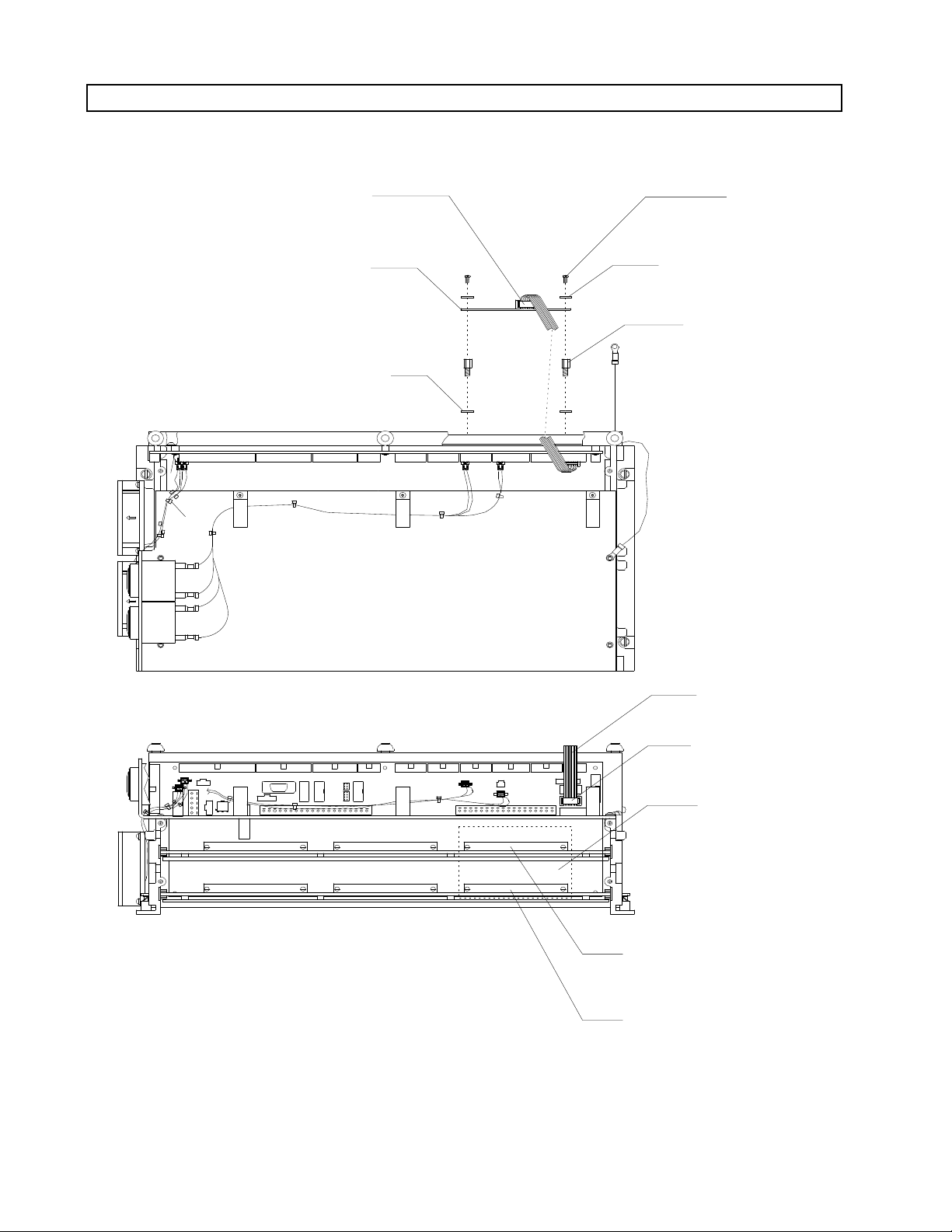
6. Remove the four backplane
mountingscrewsatconnectorsJ35
andJ38.SeeFigure1.
7. Replacethesescrewswithfour3-48
x5/16in.panheadscrews(P/N
HW02031).
8. Onthefrontsideofthebackplane
support,installfour3-48x5/16in.
hexstandoffsand#3lockwashersas
showninFigure1.
9. InstalltheNM4DatagripPCB
assemblyontothestandoffswith
four3-48x5/16in.panheadscrews.
Ensurethattheboardisoriented
withJ1atthetop.
10. Installtheten-cond.ribboncable
(P/N4112579-005)fromJ1onthe
NM4DatagripboardtoJ31onthe
backplane.SeeFigure1.
11. Carefullyreinstallthetwoprocessor
assembliesintheircorrectpositions
inthecardcage.
5. Removebothprocessorassemblies
fromthecardcage.Marktheupper
andlowerassembliessotheycanbe
reinstalled in their original
positions.
1
Page 2
RETURN TO SERVICE PROCEDURE TABLE OF CONTENTS
INSTALLATION PROCEDURE (continued)
RETURN TO CD-ROM TABLE OF CONTENTSRETURN TO CD-ROM TABLE OF CONTENTS
NM4 DATAGRIP
PCB ASM J1
NM4 DATAGRIP
PCB ASM
(P/N 4112027)
LOCKWASHERS (4X)
(P/N HW68005)
MOUNTING
SCREWS (4X)
(P/N HW02026)
LOCKWASHERS (4X)
(P/N HW67014)
STANDOFFS (4X)
(P/N 4110589-020)
TOP VIEW OF
CARD CAGE ASSEMBLY
J42.
J41.
J20.
J21.
J22.
J31.
FRONT VIEW OF
CARD CAGE ASSEMBLY
SP11301
Figure 1: NM4 DATAGRIP PCB ASSEMBLY INSTALLATION
RIBBON CABLE
BACKPLANE J31
DATAGRIP PCB
ASSEMBLY
MOUNTING AREA
(OTHER SIDE)
J35 (REPLACE MOUNTING
SCREWS - SEE TEXT)
J38 (REPLACE MOUNTING
SCREWS - SEE TEXT)
2
Page 3
SP11302
OXIMETER.
SENSOR.R.
REMOTE.R.
DISPLAY..
BP CUFF..
DATAGRIP.
SIDE VIEW OF
PATIENT INTERFACE PANEL
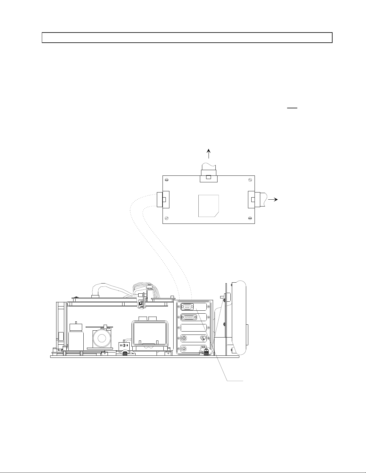
DATAGRIP INTERFACE
PANEL AND CABLE
ASSEMBLY (INSTALL)
(P/N 4112171)
ORDM
DATAGRIP
PCB ASM J1
FRONT VIEW OF
NM4 DATAGRIP PCB
ASSEMBLY
BACKPLANE J31
J2
J1
J3
RETURN TO SERVICE PROCEDURE TABLE OF CONTENTS
INSTALLATION PROCEDURE (continued)
RETURN TO CD-ROM TABLE OF CONTENTSRETURN TO CD-ROM TABLE OF CONTENTS
12. Remove the blank insert from the
top position of the patient interface
panel at the left side of the monitor
chassis.
13. Install the Datagrip connector panel
and cable assembly in the top
position using the hardware
removed in the previous step.
14. Connect the cable from the Datagrip
interface panel to J2 on the NM4
Datagrip PCB assembly as shown in
Figure 2.
NOTE: Skip to Step 33 if the
machine does not
have an
ORDM.
(IF APPLICABLE)
Figure 2: DATAGRIP INTERFACE PANEL AND CONNECTION
3
Page 4

RETURN TO SERVICE PROCEDURE TABLE OF CONTENTS
INSTALLATION PROCEDURE (continued)
RETURN TO CD-ROM TABLE OF CONTENTSRETURN TO CD-ROM TABLE OF CONTENTS
15. Remove any disk from the ORDM
disk drive.
16. Remove the four screws holding the
right front panel of the ventilator
box, and remove the panel.
17. Loosen the two captive screws
holding the ORDM sub-assembly to
the floor of the ventilator box.
Carefully slide the sub-assembly
forward while feeding its cables
down into the ventilator box, and
remove the sub-assembly from the
ventilator box.
18. ExaminetheORDMcompartment in
the ventilator box and verify that
there is no comb style cable conduit
in the rear of the ventilator box.
Remove any comb style conduit
before reinstalling the ORDM subassembly.
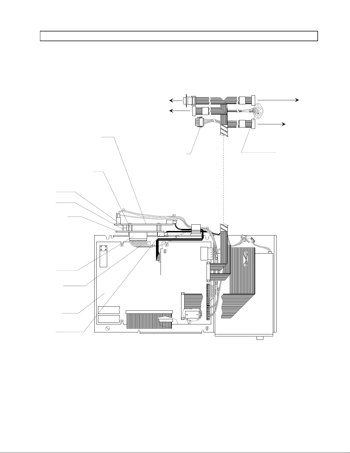
19. On the ORDM sub-assembly,
disconnect all cables from the video
interface PCB assembly (disconnect
both
ends of the cable connected to
J4 on the video interface board). See
Figure 3.
20. Remove the video interface board
from the back of the ORDM subassembly.
22. Install the new (Rev. B or later)
video interface PCB assembly (P/N
4110994) onto the standoffs with the
screws that were previously
removed. Ensure that the J3 header
on the ORDM Datagrip board mates
properly with J4 on the video
interface board.
23. Reconnect the cables to J1, J2, J3
and J5 on the new video interface
board.
24. Install the new cable assembly (P/N
4112309) between J2 on the ORDM
Datagrip board and J6 on the
ORDM CPU board.
25. Connect the new cable assembly
labeled DG (P/N 4112579-002) to J1
on the ORDM Datagrip board.
26. Position the ORDM sub-assembly in
the ventilator box, carefully feeding
the ORDM cables up into the
monitor box. Slide the sub-assembly
into place and secure it to the
ventilator box with the captive
mounting screws.
27. Reinstall the ventilator box right
front panel with the screws that
were previously removed.
21. Install the ORDM Datagrip PCB
assembly (P/N 4112239) with two 632 x 7/16 in. standoffs. Ensure that
J2 on the PCB assembly faces the
CPU board as shown in Figure 3.
4
Page 5
J3
J14
DG
J5
J4
J6
J1
J2
J3
J3
J8
J9
U32
U33
J1
SP11303
VIDEO INTERFACE
PCB ASSEMBLY
(INSTALL REV. B
OR LATER)
STANDOFF (2X)
(INSTALL)
(P/N 4110589-019)
J4
ORDM
DATAGRIP
PCB ASM
(INSTALL)
J3
J2
NEW
CABLE
(INSTALL)
J1
CPU
BOARD
TOP VIEW OF ORDM SUB-ASSEMBLY
TO
BACKPLANE
J14
KEYBOARD
CONNECTOR
TO NM4
DATAGRIP
PCB ASM J3
TO BACKPLANE J13
TO BACKPLANE J3
POWER
CONNECTOR
RETURN TO SERVICE PROCEDURE TABLE OF CONTENTS
INSTALLATION PROCEDURE (continued)
RETURN TO CD-ROM TABLE OF CONTENTSRETURN TO CD-ROM TABLE OF CONTENTS
Figure 3: ORDM DATAGRIP BOARD AND CONNECTIONS
5
Page 6
RETURN TO SERVICE PROCEDURE TABLE OF CONTENTS
INSTALLATION PROCEDURE (continued)
RETURN TO CD-ROM TABLE OF CONTENTSRETURN TO CD-ROM TABLE OF CONTENTS
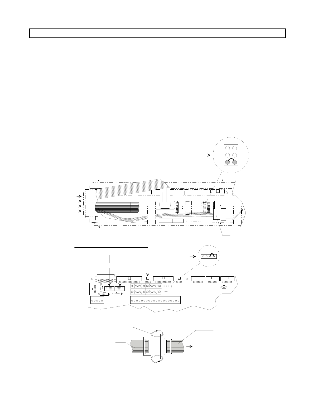
28. Reconnect the ORDM cables to J3,
J13 and J14 on the backplane.
Connector locations are shown in
Figure 4.
29. Reconnect the floating ORDM
keyboard and power cables. Route
them through the backplane cable
clamps as they were originally.
30. Connect the new DG cable to J3 on
the NM4 Datagrip PCB assembly
(ref. Figure 2).
FROM
ORDM
J13.
31. Verify that along with the existing
jumpers, there is a jumper from
JP19-5 to JP19-6 on the new type
backplane (P/N 4111881), or from
JP19-3 to JP19-4 on the old type
backplane (P/N 4110699) as shown
in the detail in Figure 4.
J3..
J19.
J40.
J19
1
3
5
J14.
2
4
6
FRONT VIEW OF NM4 BACKPLANE
(PARTIAL) (LATER MODELS)
FROM
ORDM
J13
TIE STRAP (2X)
PRINTER ADAPTER CABLE
SP11304
(P/N 4106068)
J14
FRONT VIEW OF NM4 BACKPLANE
J3
(PARTIAL) (EARLY MODELS)
J19
TO J13
4
1
Figure 4: ORDM CABLE CONNECTIONS TO BACKPLANE
KEYBOARD
CONNECTOR
ORDM CABLE (DB9)
6
Page 7

QWERT YUIOP
ASDFGHJKL
ZXCVBNM
[
{
]
}
;
'
:
"
,
/
<
>?
BKSPESC
1 23456 7890-
=
\
+_)(*&^%$#@!
.
MONITOR
ENTER
ARTIFACTCONFIG
ALT
CONTROL
PAGE
START/
STOP
RECORD
PRINT
RECORD
EDIT
SP11305
DRUGS
PATIENT
DATA
EVENTS NUMERIC GRAPHIC
DELETE
ENTRY
STAT
DRUG
STAT
EVENT
SELECT
ENTRY
|
SHIFT
CAPS
LOCK
START/STOP RECORD
KEYCAP
(P/N S010183)
EDIT KEYCAP
(P/N S010184)
RETURN TO SERVICE PROCEDURE TABLE OF CONTENTS
INSTALLATION PROCEDURE (continued)
RETURN TO CD-ROM TABLE OF CONTENTSRETURN TO CD-ROM TABLE OF CONTENTS
32. Pull out the keyboard and verify
that the EDIT and START/STOP
RECORD keycaps are installed as
shown in Figure 5.
If either of these keycaps are not present,
remove the keyboard cover and carefully lift
off the existing keycap(s). Press the new
keycap(s) into place. Clean the keyboard
faceplate and install a new keyboard cover
(P/N 4111314).
Figure 5: KEYBOARD LAYOUT WITH CORRECT KEYCAPS
7
Page 8

RETURN TO SERVICE PROCEDURE TABLE OF CONTENTS
INSTALLATION PROCEDURE (continued)
RETURN TO CD-ROM TABLE OF CONTENTSRETURN TO CD-ROM TABLE OF CONTENTS
33. Remove the cable clamps holding
the remote display cable to the
underside of the boom arm.
34. Remove the plastic cap at the
outboard end of the boom arm to
expose the remote display mounting
screw.
35. While holding the remote display
assembly, loosen the mounting
screw until the assembly separates
from the boom arm.
36. Install the Datagrip assembly (see
Figure 6) to the boom arm. Be sure
the delrin spacer is in place between
the assembly and the boom arm.
Tighten the mounting screw to a
torque of 3 to 5 foot pounds.
Reinstall the plastic cap at the end
of the boom arm.
37. Remove the six screws holding the
rear cover of the remote display and
separate the rear cover from the
remote display. Use caution when
separating the cover so that cables
are not pulled from the display.
BOOM
ARM
SP11306
Figure 6: DATAGRIP INSTALLATION
CAP
DATAGRIP
ASSEMBLY
(P/N 4111907)
8
Page 9

RETURN TO SERVICE PROCEDURE TABLE OF CONTENTS
INSTALLATION PROCEDURE (continued)
RETURN TO CD-ROM TABLE OF CONTENTSRETURN TO CD-ROM TABLE OF CONTENTS
38. Loosen the remote display clamp
screws. See Figure 7. Remove the
outer retaining ring from the remote
display mountingrod, and withdraw
the rod approx. 3 in. until the end of
the rod clears the first clamp.
Remove the inner reaining ring and
fullywithdraw the display mounting
rod.
39. Examine the mounting rod hole in
the remote display rear cover. If the
hole does not have a notch as shown
in the illustration, carefully cut or
file a in. wide notch in the cover
that will clear the stop pins on the
new Datagrip display mounting rod.
40. Replace any cracked display
mounting clamps (P/N 4112685-001
mounting blocks) at this time with
the spare clamps provided in the
parts kit.
41. Reinstall the rear cover on the
remote display with the screws that
were previously removed. (Install
the two shorter screws at the
bottom.)
42. Slide the remote display onto the
Datagrip display mounting rod.
Orient the display with its face
toward the floor so that the stop
pins on the rod will pass through
the slots in the mounting clamps,
and continue sliding the display into
position.
43. Tighten the mounting clamps
(accessible through clearance holes
in the rear cover) until the remote
display has the desired amount of
friction on the mounting rod.
EXISTING
DISPLAY
MOUNTING
ROD (REMOVE)
NOTCH
SP11307
MOUNTING BLOCK (2X)
(P/N 4112685-001)
PS2.
PS1.
J1..
J2..
J1.
J2.
J3.
CUTAWAY - REAR VIEW OF REMOTE DISPLAY
INNER RETAINING
RING (REMOVE)
OUTER RETAINING
RING (REMOVE)
REAR
COVER
SCREWS
(4X)
CLAMP
SCREWS
REAR COVER
SCREWS (2X)
Figure 7: REMOTE DISPLAY DETAILS
9
Page 10

RETURN TO SERVICE PROCEDURE TABLE OF CONTENTS
INSTALLATION PROCEDURE (continued)
RETURN TO CD-ROM TABLE OF CONTENTSRETURN TO CD-ROM TABLE OF CONTENTS
44. Connect the Datagrip and remote
display cables to their ports on the
patient interface panel as shown in
Figure 8.
45. Route the Datagrip and remote
display cables along theunderside of
the boom arm: attach the cables to
the outer section of the boom arm
with two in. cable clamps. Coil the
excess length of the cables and
secure them to the inner section of
the boom arm with two ¾ in. cable
clamps.
Ensure that the boom arm has full
range of motion with no binding
caused by the cables.
46. Restore power to the machine and
enable the circuit breakers by
pressing in their buttons.
47. Proceed to the SOFTWARE
LOADING AND TEST section.
10
Page 11

SP11308
PATIENT
INTERFACE
PANEL
BP CUFF
REMOTE
DISPLAY
DATAGRIP
OXIMETER
SENSOR
3/4 IN. CABLE
CLAMPS
(P/N 4106649)
DATAGRIP AND REMOTE
DISPLAY ASSEMBLY
3/8 IN. CABLE
CLAMPS
(P/N 412300)
RETURN TO SERVICE PROCEDURE TABLE OF CONTENTS
INSTALLATION PROCEDURE (continued)
RETURN TO CD-ROM TABLE OF CONTENTSRETURN TO CD-ROM TABLE OF CONTENTS
Figure 8: DATAGRIP AND REMOTE DISPLAY CABLE INSTALLATION
11
Page 12

SOFTWARE LOADING AND TEST
NM4 Software Loading:
The following items are needed:
RETURN TO SERVICE PROCEDURE TABLE OF CONTENTS
RETURN TO CD-ROM TABLE OF CONTENTSRETURN TO CD-ROM TABLE OF CONTENTS
-- Interface Cable, NAD Part No.
4109882 P (9-pin to 25-pin) or
4110328 A (9-pin to 9-pin)
-- IBM
®
PC or IBM PC Compatible
configured with:
• PC-DOS or MS-DOS V3.3 or higher
• RS-232C Serial Port connected to
COM 1
• Hard Drive loaded with NM4 1.21 or
later Software
• Modem (or external modem)
48. Call the NAD Technical Service
Departmentand obtain the following
information for downloading
NARKOMED 4 Software Release
1.21 or later:
•System configuration
•Communications protocol
•CRC value
49. Download the software to the hard
disk on the PC.
50. Set the System Power switch on the
NARKOMED 4 to STANDBY, and
the power switch on the PC to OFF.
51. Connect the appropriate interface
cable (9-pin or 25-pin) to COM 1 on
the PC, and connect the other end of
the cable to the NM4 serial interface
Port A as shown in Figure 9.
53. Power up the PC and wait for the
DOS prompt to appear on the
screen.
54. Set the PC to read the drive holding
the software. For example: if the
software was downloaded to drive C,
type C: and press ENTER.
55. Type LOAD_NM4 and press
ENTER. Note that the character
between LOAD and NM4 is an
underline.
56. The PC program will print the
version number and ask for
verification. Press ENTER to
proceed. The PC screen is shown in
Figure 11.
57. Verify that the CRC value shown on
the PC screen matches the one
obtained from the NAD Technical
Service Department. After several
minutes have elapsed, the NM4 will
auto re-boot and will enter a powerup sequence with the new software
version number displayed.
58. After the NM4 re-boots, press the
ESC key on the PC.
59. Set the System Power switch on the
NM4 to STANDBY, and the power
switch onthe PC toOFF. Disconnect
the interface cable.
52. Press and hold the MONITOR
SETUP and TREND keys, and turn
the System Power switch to ON.
Release the MONITOR SETUP and
TREND keys when the load mode
screen shown in Figure 10 appears.
12
Page 13

ABPRINTER
C D
SERIAL INTERFACE
ASSEMBLY
NARKOMED 4
REAR VIEW
PORT A
RETURN TO SERVICE PROCEDURE TABLE OF CONTENTS
SOFTWARE LOADING AND TEST (continued)
RETURN TO CD-ROM TABLE OF CONTENTSRETURN TO CD-ROM TABLE OF CONTENTS
Figure 9: NARKOMED 4 EXTERNAL SOFTWARE LOAD INTERFACE CONNECTION
13
Page 14

RETURN TO SERVICE PROCEDURE TABLE OF CONTENTS
SOFTWARE LOADING AND TEST (continued)
RETURN TO CD-ROM TABLE OF CONTENTSRETURN TO CD-ROM TABLE OF CONTENTS
FIRMWARE TESTS
BOOT PROGRAM PASS (C) COPYRIGHT 1988-1990, NAD INC.
NAD NM4 PROCESSOR BOOT ROM
VERSION: 1.2
NM4 SOFTWARE LOADER
MAIN
WAITING FOR INPUT
FIGURE 10: NARKOMED 4 LOAD MODE SCREEN
A:\>load_nm4
A:\>ECHO OFF
Ready to loadNM4 Software at
**** NM4 Software - Version 1.11 ****
Enter CTRL C to ABORT
Strike a key when ready...
NM4 Software Image Transfer Program (V1.0)
* Copyright (c) 1990 by NAD, Inc. *
port : COM1 file : NM4.IMG baud rate : 38400
READY TO TRANSMIT Software Version 1.11 SIZE=1048320 bytes CRC=CF39
Press ESC to exit
xxxxxxx bytes sent
FIGURE 11: SOFTWARE LOAD PC SCREEN
14
Page 15

RETURN TO SERVICE PROCEDURE TABLE OF CONTENTS
SOFTWARE LOADING AND TEST (continued)
RETURN TO CD-ROM TABLE OF CONTENTSRETURN TO CD-ROM TABLE OF CONTENTS
NM4 Test:
60. Turn the System Power switch to
ON.
61. Following the power-up diagnostics,
verify that the Datagrip softkeys
appear on the remote display. If a
stacked gas bar appears, check the
cable connection from the backplane
to the NM4 Datagrip board. Replace
the cable or NM4 Datagrip board if
necessary.
62. Press the BACKUP hard key. Verify
thatthe Datagripsoftkeys appear on
the remote display when the backup
processor is selected. If a stacked
gas bar appears, swap the
processors.
63. Rotate the Datagrip selector wheel
and verify that the cursor moves
correctly on the remote display. Pull
the Datagrip trigger and verify that
the selected softkey highlights.
ORDM Software Update:
64. Turn the System Power switch to
STANDBY.
65. Insert the ORDM Software (2.0 or
later) Program Disk into the disk
drive, pressing it in until it locks
into place. See Figure 12.
66. Turn the System Power switch to
ON, and wait for the Monitors
screen to appear on the display.
67. Press and hold the MONITOR and
SYSTEM CONFIG keys, and press
the Selection Dial to enter the Main
Service Screen as shown in Figure
13.
68. Touch the PERIPHERALS soft key
at the bottom right of the service
screen.
If the Datagrip does not function
properly, check the external
connection to the interface panel,
and the internal connection fromthe
interface panel to the NM4 Datagrip
board.
NOTE: If the image on the remote
display is not stable
following the Datagrip
installation,contact theNAD
Technical Service
Department.
NOTE: Skip to Step 80 if the
machine does not
have an
ORDM.
15
Page 16

WRITE-PROTECT
TAB
DISK
SLOT
EJECT BUTTON
INDICATOR LIGHT
RETURN TO SERVICE PROCEDURE TABLE OF CONTENTS
SOFTWARE LOADING AND TEST (continued)
RETURN TO CD-ROM TABLE OF CONTENTSRETURN TO CD-ROM TABLE OF CONTENTS
Figure 12: O.R. DATA MANAGER DISK DRIVE
SERVICE
MACHINE SERIAL NUMBER : 00124001
LAST SERVICE DATE : 07-14-91
HOURS RUNNING SINCE LAST SERVICE : 97
TOTAL HOURS RUNNING : 5610
POWER OFF MACHINE TO INVOKE NEW CALIBRATION VALUES
MAIN
SERVICE
LOG
PMS
CRITERIA
SERVICE CODE
VIEW
Figure 13: VIEW MODE SERVICE SCREEN
16
MONITORS
PERIPHERALS
Page 17

RETURN TO SERVICE PROCEDURE TABLE OF CONTENTS
SOFTWARE LOADING AND TEST (continued)
RETURN TO CD-ROM TABLE OF CONTENTSRETURN TO CD-ROM TABLE OF CONTENTS
69. Touch the Remote Panel Relay
ORDM soft key (see Figure 14) on
the Relays Status and Control
Screen.
70. Observe the remote display during
the procedure. Downloading is
complete when the message
"REMOVE THE FLOPPY DISK
FROM THE FLOPPY DRIVE AND
DEPRESS ANY KEY" appears on
the remote display.
71. Press the eject button on the disk
drive. The disk will partially selfeject from the drive.
NOTE: Be sure to remove the disk
before pressing the spacebar.
72. Remove the disk from the disk drive
and press the spacebar on the O.R.
DATA MANAGER keyboard.
73. Touch the Remote Panel Relay NM4
soft key on the Relays Status and
Control Screen.
74. Press the MONITOR key on the
NARKOMED 4 panel.
75. Wait for the "ORDM NOT REC"
message to appear on the remote
display advisory column.
76. Press the START/STOP key on the
ORDM keyboard.
77. Insert a blank patient data disk in
the ORDM disk drive and press the
spacebar. When the message "OK
TO CLEAR PREVIOUS CASE
FROM DISK" appears, press the Y
key. When the message "ARE YOU
SURE" appears, press the Y key
again.
RELAYS STATUS AND CONTROL SCREEN
PRINTER RELAY:
REMOTE PANEL RELAY:
ORDM NM4
ORDM NM4
RELAYS
DUMP
MAIN
SERVICE
LOG
PMS
CRITERIA
MONITORS
PERIPHERALS
Figure 14: RELAYS STATUS AND CONTROL SCREEN
17
Page 18

RETURN TO SERVICE PROCEDURE TABLE OF CONTENTS
SOFTWARE LOADING AND TEST (continued)
RETURN TO CD-ROM TABLE OF CONTENTSRETURN TO CD-ROM TABLE OF CONTENTS
78. When the patient name and/or ID
screen appears, enter a "1" in the
patient ID block and press the
ENTER key twice to advance the
cursor and start the case.
79. Verify that the software has been
properly downloaded: On the
keyboard, press and hold the ALT
key, and press the V key.
The window shownin Figure 15 will appear
at the center of the remote display for
approximately three seconds. The current
software version number shown on the
remote display should agree with that
marked on the program disk or its
accompanying documentation.
ORDM S/W Ver x.x (xxxxH)
Figure 15: SOFTWARE VERSION WINDOW
80. Turn the System Power switch to
STANDBY.
81. Disconnect the remote display and
Datagrip cables from their ports on
the patient interface panel.
82. Reinstall the monitor box cover.
83. Reinstall all connections to the
patient interface panel.
84. Ensure that an updated copy of the
Operator’s Manual (P/N S4111402)
accompanies the machine.
85. Perform a complete PMS on the
machine.
18
Page 19

NORTH
RETURN TO SERVICE PROCEDURE TABLE OF CONTENTS
RETURN TO CD-ROM TABLE OF CONTENTSRETURN TO CD-ROM TABLE OF CONTENTS
AMERICAN
DRÄGER
Technical Service Department
3122 Commerce Drive
Telford, PA 18969
(215) 721-5402
(800) 543-5047
(215) 723-5935 Fax
Quality Service for Life
®
Part Number: SP00113
Rev: B
Date: May 30, 1996
© 1996 N.A.D., Inc.
 Loading...