

Page 1
Kreissystem 8 ISO
Circle Absorption
System 8 ISÖ
Gebr+uchsanweisung
Instructions for Use
Nur zum Draeger-internen Gebrauch. Gilt nicht als Gebrauchsanweisung!
Page 2
Inhalt
,
4
Conte&
Zu Ihrer und Ihrer Patienten Sicherheit ................... 3
Verwendungszweck ................................................... 4
Wirkungsweise/Möglichkeiten der Narkoseführung ... 4
- Halbgeschlossenes System ..................................... 4
- Halboffenes System ................................................. 8
- C02-Absorber .......................................................... 8
- CO,-Anreicherung ................................................... 9
SicherheitsmaEnahmenlVorschriften und
Empfehlungen .............................................................. 10
Kreissystem aufbauen ............................................... 13
- CO,-Absorber und Inspirationsventil ...................... 13
- Drucküberwachung .................................................. 13
- Volumeter und Exspirationsventil ............................. 14
- 0~.Überwachung ..................................................... 14
- Atembeutel ............................................................... 15
- Beatmungsgerät ....................................................... 16
- Frischgasversorgung ............................................... 16
- Narkosegasfortleitung .............................................. 17
- Atemschläuche ......................................................... 18
- Wasserabscheider ................................................... 18
- Mikrobenfilter ........................................................... 18
Kurzprüfung vor jedem Einsatz ................................ 19
Narkosebetrieb ........................................................... 21
- Narkoseführung ........................................................ 21
Nur zum Draeger-internen Gebrauch. Gilt nicht als Gebrauchsanweisung!
- Schnellentlüftu”g/Spülung ....................................... 21
- CO,-Absorber (Handhabung) ................................. 22
- Weiterverwendung des Kreissystems
am nächste” Patienten ............................................ 23
Betriebsende, Entsorgung ...................... .................. 23
Pflege .......................................................................... 24
- Kreissystem zerlegen ............................................... 24
- VordesinfektionlReinigung ....................................... 25
- Desi”fektion/Sterilisation ......................................... 26
- Behandlung von Gummiteilen .................................. 26
- Zusammenbau .................................................... . ..... 27
- CO,-Absorber fülle” ................................................ 27
Funktionsprüfung nach jeder Pflege ........................ 26
- Prüfung am Prüfgerät .............................................. 28
- Prüfung am Narkosegerät ........................................ 28
Instandhaltungsintervalle .......................................... 31
Technische Daten ....................................................... 31
Bestell-Liste ................................................................ 32
Teile-Liste .................................................................... 34
Hinweis auf Technischen Kundendienst .................. 36
For Your Safety and that of Your Patients .............. 3
Intended Use .............................................................. 4
Made of OperationlPotentials of Anaesthesia ........... 4
- Semi-closed System ................................................ 4
- Semi-open System ................................................... 8
- CO2 Absorber .......................................................... 8
- CO2 Enrichment ...................................................... 9
Safety Precautions/
Rules and Recommendations ...................................... 10
Assembly of the Circle Absorption System ............. 13
- CO2 Absorber and Inspiratory Valve ...................... 13
- Pressure Monitoring ................................................ 13
- Volumeter and Expiratory Valve ............................... 14
- O2 Monitoring .......................................................... 14
- Breathing Bag .......................................................... 15
- Ventilator .................................................................. 16
- Fresh-Gas Supply .................................................... 16
- Anaesthetic-Gas Scavenging ....................... .......... 17
- Breathing Hoses ........................................... .......... 18
- Water Separators .................................................... 18
- Microbial Filter ......................................................... 18
Brief Check Prior to each Use .................................. 20
Anaesthesia ................................................................ 21
- Performance of Anaesthesia .................................... 21
- Rapid VentinglFlushing ............................................ 21
- CO* Absorber (handling) ........................................ 22
- Repeated Use of the Circle System with
another Patient ......................................................... 23
Shutdown, Disposal ................................................... 23
Gare ............................................................................. 24
- Disassembly of the Circle Absorption System ........ 24
- DisinfectionlCleaning ............................................... 25
- DisinfectionlSterilisatio” .......................................... 26
- Treatment of Rubber Parts ..................................... . 26
- Assembly .................................................................. 27
- Filling the CO* Absorber ......................................... 27
Functional Check following each Gare .................... 28
- Testing with a Tester ............................................... 28
- Testing on the Anaesthetic Machine ....................... 28
Maintenance Intervals ................................................ 31
Technical Data ............................................................ 31
Order List .................................................................... 32
Parts List ..................................................................... 34
Page 3
Zu Ihrer und Ihrer Patienten
Sicherheit
For Your Safeiy and That of Your
Patients
Das Gesetz über technische Arbeitsmittel (Gerätesicherheitsgesetz) und die Medizingeräteverordnung (MedGV)
schreiben vor, auf folgendes hinzuweisen ‘j:
Gebrauchsanweisung beachten
Jede Handhabung an dem Gerät setzt die genaue Kenntnis und Beachtung dieser Gebrauchsanweisung vorsaus.
Das Gerät ist nur für die beschriebene Verwendung bestimmt.
/“standhaltung
Das Gerät muß halbjährlich Inspektionen und Wartangen
durch Fachleute unterzogen werden (mit Protokoll).
Der Abschluß eines Service-Vertrags mit dem
DrägerService wird empfohlen.
Instandsetzungen am Gerät nur durch den
DrägerService.
Bei Instandhaltung nur Original-Dräger-Tei verwenden.
Kapitel “lnstandha/tungsinterva//e~ beachte”.
Sicherheitstechnische Kontrollen
Das Gerät wiederkehrenden sicherheitstechnischen Kontrollen unterziehen - wie in der Bescheinigung gemäß
MedGV vorgeschrieben.
Nur zum Draeger-internen Gebrauch. Gilt nicht als Gebrauchsanweisung!
Zubehör
Nur das in der Bescheinigung zur MedGV aufgeführte
Zubehör verwenden.
Anderes Zubehör nur verwenden, wen” eine Bescheinigung zur sicherheitstechnisch unbedenklichen Verwendungsfähigkeit vorhegt.
Haftung für Funktion bzw. Schäden
Die Haftung für die Funktion des Gerätes geht in jedem
Fall auf den Eigentümer oder Betreiber über, soweit das
Gerät von Personen, die nicht dem DrägerService angehören, unsachgemäß gewartet oder instandgesetzt wird
oder wenn eine Handhabung erfolgt, die nicht der bestimmungsgemäßen Verwendung entspricht.
Für Schäden, die durch die Nichtbeachtung der vorstehenden Hinweise eintreten, haftet die Drägerwerk Aktiengesellschaft nicht. Gewährleistungs- und Haftungsbedingungen der Verkaufs- und Lieferbedingungen der
Drägerwerk Aktiengesellschaft werden durch vorstehende Hinweise nicht erweitert.
Drägerwerk Aktiengese//schaft
For correct and effective use of the equipment and to
avoid hazards it is essential to read the following recom-
mendations and to act accordingly’%
StricUy follow the instrucCons for use
Any use of the equipment requires fuli understanding and
stritt observation of these instructions. The equipment is
only to be used for purposes specified here.
Maintenance
The equipment must be inspected and serviced by ex-
perts at regular 6 month intervals (and a record kept).
We recommend obtaining a service contract with Dräger-
Service.
Repairs and general overhaul of the equipment may only
be carried out by DrägerService.
On/y original Dräger spare Parts may be used for mainte-
“a”Ce.
Observe chapter *Maintenance /nterva/sw.
Liabimy for proper function or darnage
The tiabi/ity for the proper function of the equipment is ir-
revocably transferred to the owner or operator to the ex-
tent that the equipment has been serviced or repaired by
personnel not employed or authorized by DrägerService
or when the equipement was used in a manner not conforming to its intended use.
Drägerwerk Aktiengesellschaft cannot be held responsible for darnage caused by non-compliance with the recommendations given above. The warranty and /iabi/ity
provisions of the terms of sale and delivery oi Dräger-
werk Aktiengesellschaft arc likewise not modified by the
recommendations given above.
Drägerwerk Aktiengesellschaft
Page 4
Verwendungszweck
Intended Use
Atemsystem für Inhalations-hlarkose-
geräte, speziell für den Betrieb als
athalbgeschlossenes System. konzipiert. Der Betrieb als ,ahalboffenes
System. ist ebenso möglich.
Das Kreissystem ermöglicht folgende
Betriebsarten:
- Spontanatmung,
- manuelle Beatmung,
- automatische Beatmung mit
a) Druckbegrenzung am Kreissy-
stem,
b) Druckreserve des Beatmungs-
gerätes.
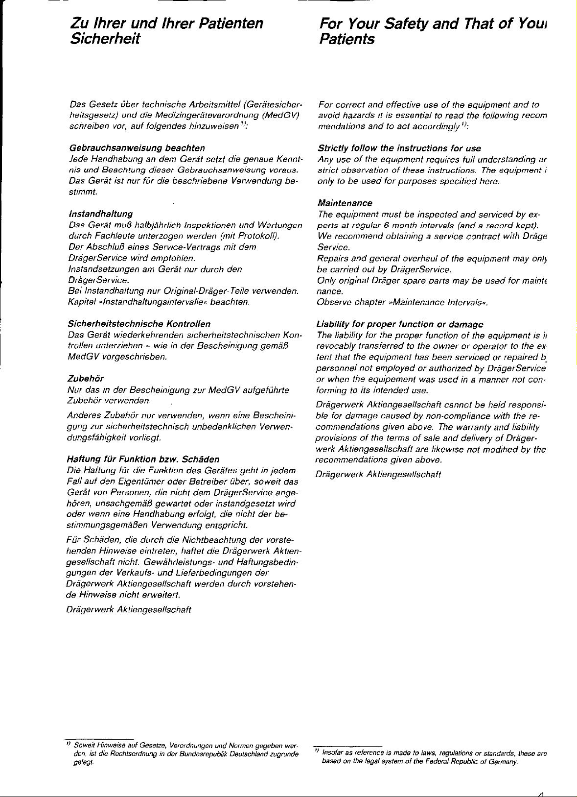
Kreissystem 8 ISO und 8 isoclic
entsprechen der ISO-Norm und DIN
13252 (konische Anschlüsse).
Kreissystem 8 isoclic ist zusätzlich
mit Schlauchsicherungen a>isoclic<~
gegen unbeabsichtigte Diskonnektion
ausgerüstet.
Kreissystem 7a hat Anschlußtüllen nach
Dräger-Norm, die sich in Form (nicht
konisch) und Durchmesser (23 mm) von
der ISO-Norm unterscheiden. Diese An-
Nur zum Draeger-internen Gebrauch. Gilt nicht als Gebrauchsanweisung!
schlüsse sind im Geltungsbereich von
DIN 13252 nicht zugelassen.
Breathing system for inhalational
anaesthetic machines, particularly designed for use as a nsemi-closed system- (partial rebreathing System) but
tan also be used as a ,osemi-open
systew.
The circle System facilitates the following operating modes:
- Spontaneous breathing
- Manual ventilation
- Automatic Ventilation with
a) pressure limitation at the circle
system
b) pressure reserve of the ventila-
tor.
Circle System 8 ISO and 8 isoclic
conform to the ISO Standard and
DIN 13252 (conical connections).
Circle System 8 isoclic is additonally
fitted with an ~4soclic<~ locking me-
chanism to prevent unintentional disconnection.
Circle System 7a is equipped with sockets according to Dräger standards. and
different from ISO Standards in shape
(not conical) and diametre (23 mm).
Such sockets arc not amxoved of within
the scope of DIN 13252:
Wirkungsweise -
Möglichkeiten der
Narkoseführung
Halbgeschlossenes System
Das halbgeschlossene System ermöglicht eine gas- und narkosemittelsparende Narkose, bei der der
Frischgasflow kleiner als das Atemminutenvolumen ist.
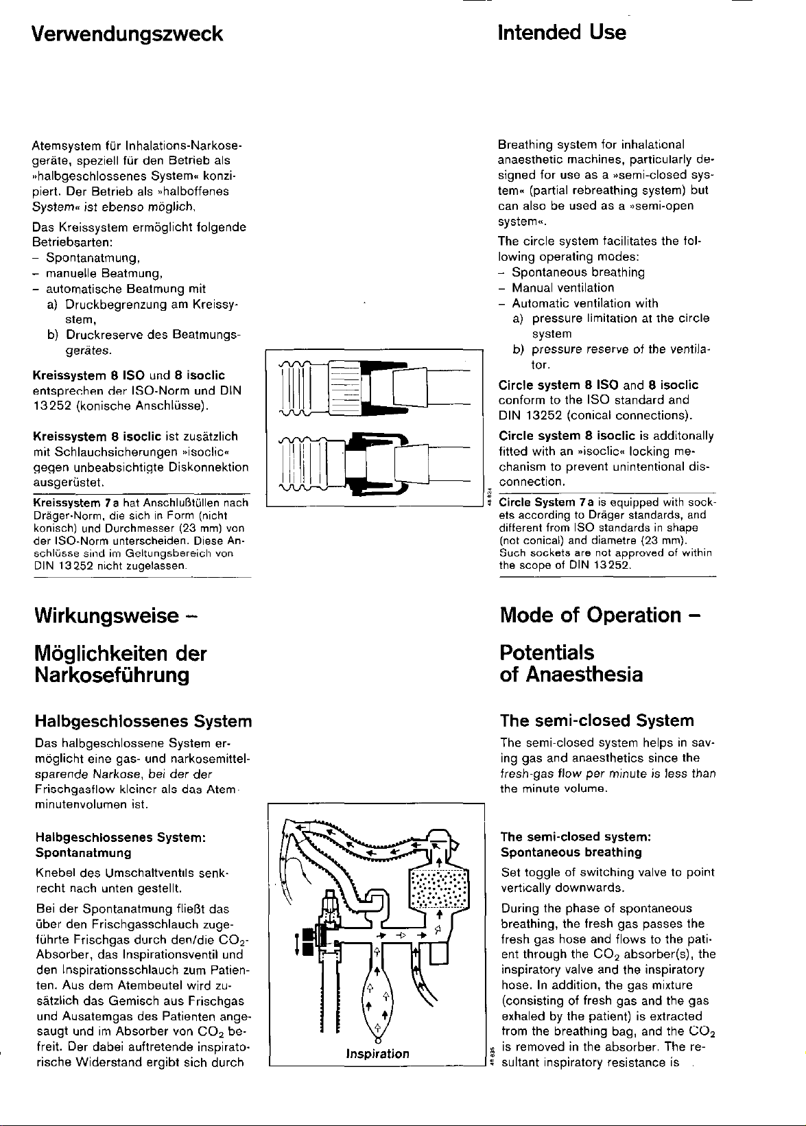
Halbgeschlossenes System:
Spontanatmung
Knebel des Umschaltventils senk-
recht nach unten gestellt.
Bei der Spontanatmung fließt das
über den Frischgasschlauch zugeführte Frischgas durch den/die CO*Absorber, das Inspirationsventil und
den Inspirationsschlauch zum Patienten. Aus dem Atembeutel wird zu-
sätzlich das Gemisch aus Frischgas
und Ausatemgas des Patienten ange-
saugt und im Absorber von CO2 be-
freit. Der dabei auftretende inspirato-
rische Widerstand ergibt sich durch
Inspiration
Mode of Operation Potentials
of Anaesthesia
The semi-closed System
The semi-closed system helps in sav-
ing gas and anaesthetics since the
fresh-gas flow per minute is less than
the minute volume.
The semi-closed system:
Spontaneous breathing
Set toggle of switching valve to Point
vertically downwards.
During the Phase of spontaneous
breathing, the fresh gas passes the
fresh gas hose and flows to the pati-
ent through the CO, absorber(s), the
inspiratory valve and the inspiratory
hose. In addition. the gas mixture
(consisting of fresh gas and the gas
exhaled by the Patient) is extracted
from the breathing bag, and the CO?
is removed in the absorber. The re-
sultant inspiratory resistance is
Page 5
Wirkungsweise
Mode of Operation
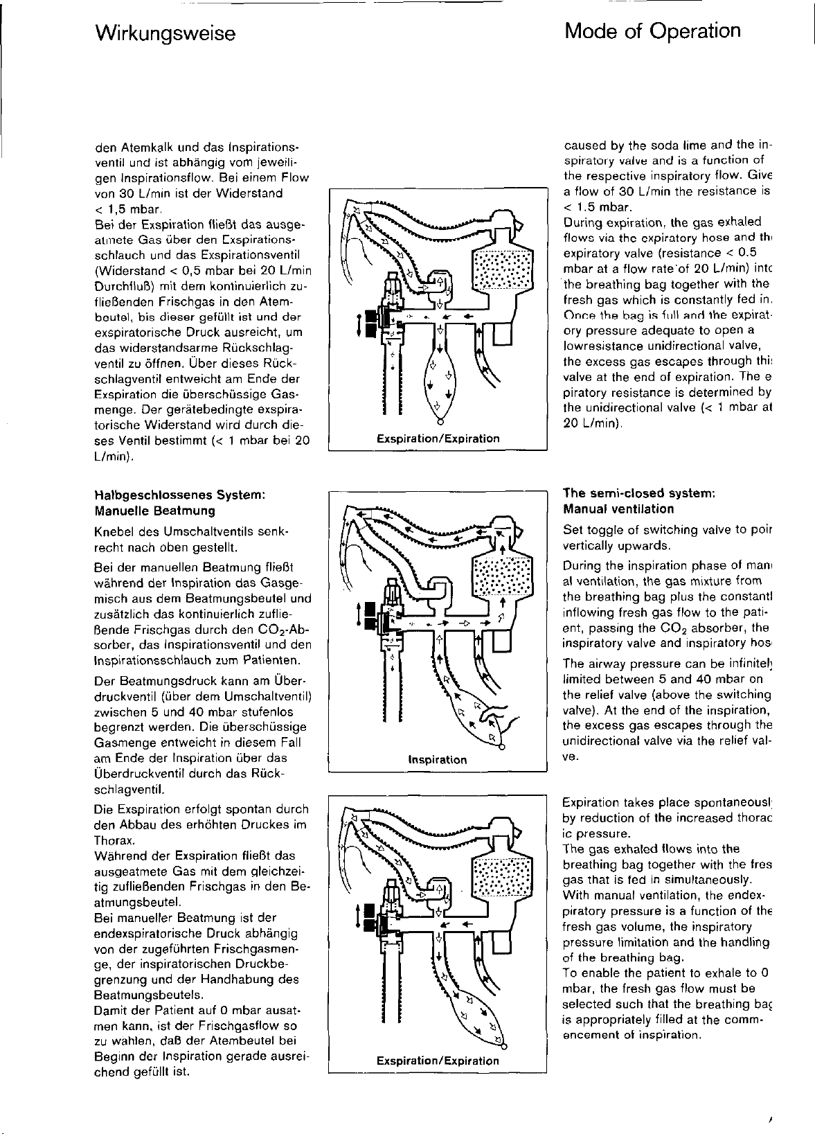
den Atemkalk und das Inspirationsventil und ist abhängig vom jeweiligen Inspirationsflow. Bei einem Flow
von 30 Llmin ist der Widerstand
< 1,5 mbar.
Bei der Exspiration fließt das ausgeatmete Gas über den Exspirationsschlauch und das Exspirationsventil
(Widerstand < 0,5 mbar bei 20 Llmin
Durchfluß) mit dem kontinuierlich zufließenden Frischgas in den Atembeutel, bis dieser gefüllt ist und der
exspiratorische Druck ausreicht, um
das widerstandsarme Rückschlagventil zu öffnen. über dieses Rückschlagventil entweicht am Ende der
Exspiration die überschüssige Gas-
menge. Der gerätebedingte exspiratorische Widerstand wird durch dieses Ventil bestimmt (< 1 mbar bei 20
Llmin).
Halbgeschlossenes System:
Manuelle Beatmung
Knebel des Umschaltventils senk-
Nur zum Draeger-internen Gebrauch. Gilt nicht als Gebrauchsanweisung!
recht nach oben gestellt.
Bei der manuellen Beatmung fließt
während der Inspiration das Gasge-
misch aus dem Beatmungsbeutel und
zusätzlich das kontinuierlich zufließende Frischgas durch den C02-Absorber, das Inspirationsventil und den
Inspirationsschlauch zum Patienten.
Der Beatmungsdruck kann am überdruckventil (über dem Umschaltventil)
zwischen 5 und 40 mbar stufenlos
begrenzt werden. Die überschüssige
Gasmenge entweicht in diesem Fall
am Ende der Inspiration über das
Überdruckventil durch das Rückschlagventil.
Die Exspiration erfolgt spontan durch
den Abbau des erhöhten Druckes im
Thorax.
Während der Exspiration fließt das
ausgeatmete Gas mit dem gleichzeitig zufließenden Frischgas in den Beatmungsbeutel.
Bei manueller Beatmung ist der
endexspiratorische Druck abhängig
von der zugeführten Frischgasmenge, der inspiratorischen Druckbegrenzung und der Handhabung des
Beatmungsbeutels.
Damit der Patient auf 0 mbar ausatmen kann, ist der Frischgasflow so
zu wählen, daß der Atembeutel bei
Beginn der Inspiration gerade ausreichend gefüllt ist.
Exspiration/Expiration
1
Inspiration
Exspiration/Expiration
caused by the soda lime and the inspiratory valve and is a function of
the respective inspiratory flow. Given
a flow of 30 Limin the reslstance is
< 1.5 mbar.
During expiration. the gas exhaled
flows via the expiratory hose and the
expiratory valve (resistance < 0.5
mbar at a flow rate’of 20 L/min) into
the breathing bag together with the
fresh gas which is constantly fed in.
Once the bag is full and the expiratory pressure adequate to open a
lowresistance unidirectional valve,
the excess gas escapes through this
valve at the end of expiration. The ex-
piratory resistance is determined by
the unidirectional valve (< 1 mbar at
20 Llmin).
The semi-closed System:
Manual Ventilation
Set toggle of switching valve to Point
vertically upwards.
During the inspiration Phase of manu-
al ventilation, the gas mixture from
the beathing bag plus the constantly
inflowing fresh gas flow to the patient, passing the CO? absorber, the
inspiratory valve and inspiratory hose.
The airway pressure tan be infinitely
limited between 5 and 40 mbar on
the relief valve (above the switching
valve). At the end of the inspiration,
the excess gas escapes through the
unidirectional valve via the relief val-
ve.
Expiration takes place spontaneously
by reduction of the increased thoracic pressure.
The gas exhaled flows into the
breathing bag together with the fresh
i gas that is fed in simultaneously.
Wath manual Ventilation, the endexpiratory pressure is a function of the
fresh gas volume, the inspiratory
pressure limitation and the handling
of the beathing bag.
To enable the Patient to exhale to 0
mbar. the fresh gas flow must be
selected such that the breathing bag
is appropriately filled at the comm-
! encement of inspiration.
Page 6
Wirkungsweise
Mode of Operatlon
7
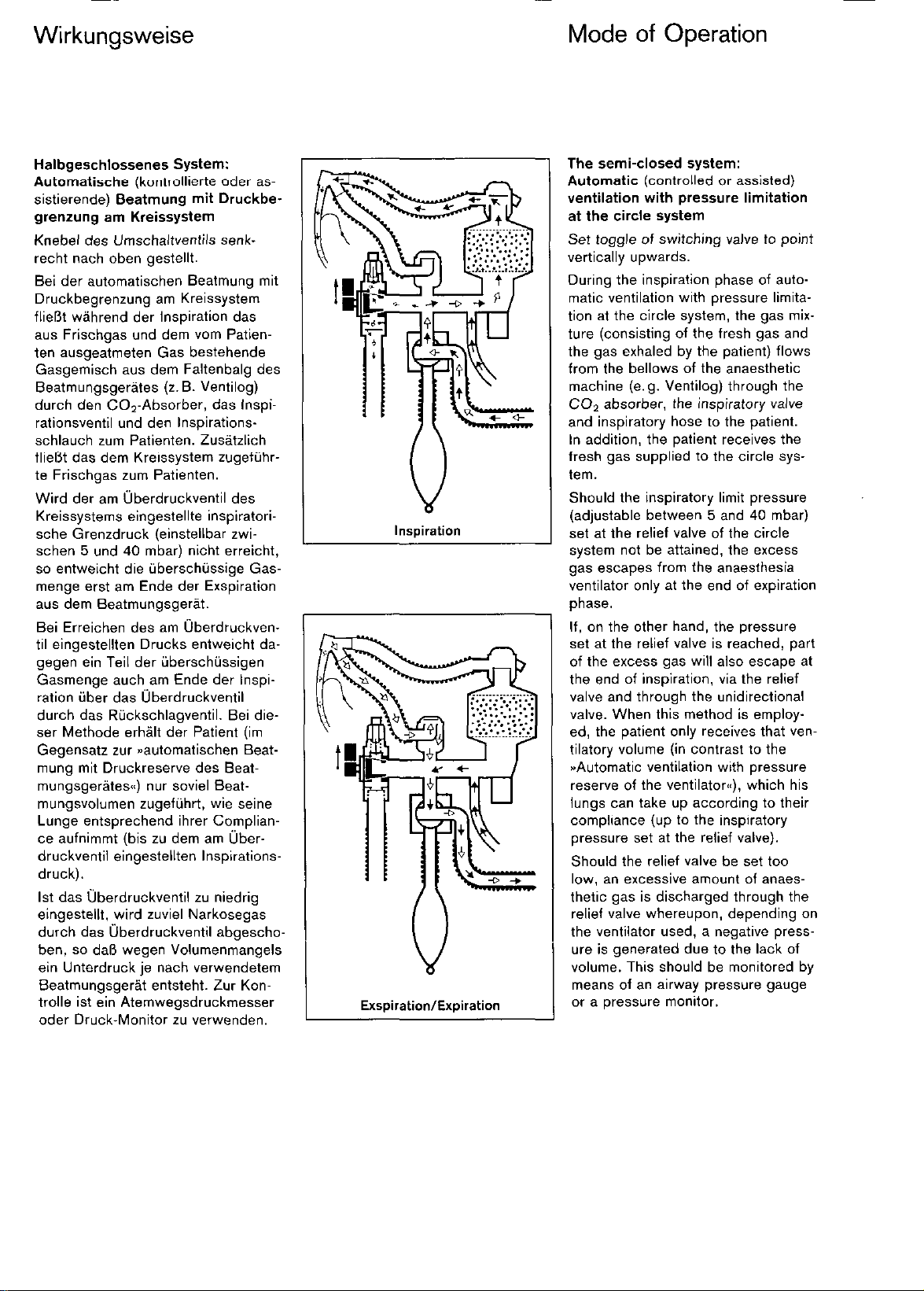
Halbgeschlossenes System:
Automatische (kontrollierte oder as-
sistierende) Beatmung mit Druckbegrenzung am Kreissystem
Knebel des Umschaltventils senkrecht nach oben gestellt.
Bei der automatischen Beatmung mit
Druckbegrenzung am Kreissystem
fließt während der Inspiration das
aus Frischgas und dem vom Patienten ausgeatmeten Gas bestehende
Gasgemisch aus dem Faltenbalg des
Beatmungsgerätes (Z.B. Ventilog)
durch den CO*-Absorber, das Inspi-
rationsventil und den Inspirationsschlauch zum Patienten. Zusätzlich
fließt das dem Kreissystem zugeführte Frischgas zum Patienten.
Wird der am Überdruckventil des
Kreissystems eingestellte inspiratori-
sche Grenzdruck (einstellbar zwi-
schen 5 und 40 mbar) nicht erreicht,
so entweicht die überschüssige Gas-
menge erst am Ende der Exspiration
aus dem Beatmungsgerät.
Nur zum Draeger-internen Gebrauch. Gilt nicht als Gebrauchsanweisung!
Bei Erreichen des am Überdruckven-
til eingestellten Drucks entweicht da-
gegen ein Teil der überschüssigen
Gasmenge auch am Ende der Inspiration über das Überdruckventil
durch das Rückschlagventil. Bei dieser Methode erhält der Patient (im
Gegensatz zur automatischen Beatmung mit Druckreserve des Beat-
mungsgerätes<,) nur soviel Beatmungsvolumen zugeführt, wie seine
Lunge entsprechend ihrer Compliance aufnimmt (bis zu dem am überdruckventil eingestellten Inspirationsdruck).
Ist das Überdruckventil zu niedrig
eingestellt, wird zuviel Narkosegas
durch das Überdruckventil abgeschoben, so daß wegen Volumenmangels
ein Unterdruck je nach verwendetem
Beatmungsgerät entsteht. Zur Kon-
trolle ist ein Atemwegsdruckmesser
oder Druck-Monitor zu verwenden.
Inspiration
ExspirationlExpiration
The semi-closed System:
Automatic (controlled or assisted)
Ventilation with pressure limitation
at the circle System
Set toggle of switching valve to Point
vertically upwards.
During the inspiration Phase of automatic Ventilation with pressure limitation at the circle System, the gas mixtue (consisting of the fresh gas and
the gas exhaled by the Patient) flows
from the bellows of the anaesthetic
machine (e.g. Ventilog) through the
CO2 absorber, the inspiratory valve
and inspiratory hose to the Patient.
In addition, the Patient receives the
fresh gas supplied to the circle system.
Should the inspiratory limit pressure
(adjustable between 5 and 40 mbar)
set at the relief valve of the circle
System not be attained, the excess
gas escapes from the anaesthesia
Ventilator only at the end of expiration
Phase.
If, on the other hand, the pressure
set at the relief valve is reached, part
of the excess gas will also escape at
the end of inspiration, via the relief
valve and through the unidirectional
valve. When this method is employ-
ed, the Patient only receives that ven-
tilatory volume (in contrast to the
“Automatic ventilation with pressure
reserve of the Ventilatoren), which his
lungs tan take up according to their
compliance (up to the inspiratory
pressure set at the relief valve).
Should the relief valve be set too
low, an excessive amount of anaes-
thetic gas is discharged through the
relief valve whereupon, depending on
the Ventilator used, a negative press-
ure is generated due to the lack of
volume. This should be monitored by
means of an airway pressure gauge
or a pressure monitor.
Page 7
Wirkungsweise
Mode of Operation
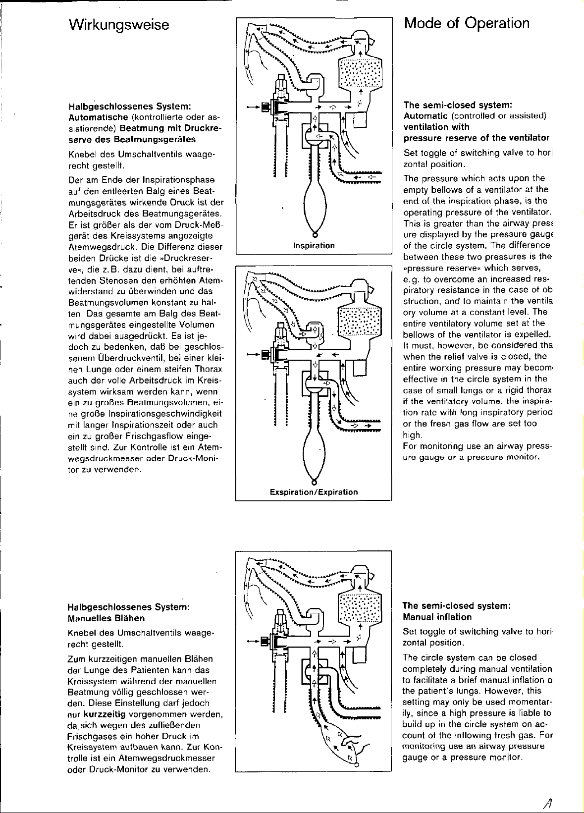
Halbg&chlossenes System:
Automatische (kontrollierte oder assistierende) Beatmung mit Druckreserve des Beatmungsgerätes
Knebel des Umschaltventils waagerecht gestellt.
Der am Ende der Inspirationsphase
auf den entleerten Balg eines Beatmungsgerätes wirkende Druck ist der
Arbeitsdruck des Beatmungsgerätes.
Er ist größer als der vom Druck-Meßgerät des Kreissystems angezeigte
Atemwegsdruck. Die Differenz dieser
beiden Drücke ist die “Druckreser-
ve«, die z.B. dazu dient, bei auftretenden Stenosen den erhöhten Atemwiderstand zu überwinden und das
Beatmungsvolumen konstant zu halten. Das gesamte am Balg des Beat-
mungsgerätes eingestellte Volumen
wird dabei ausgedrückt. Es ist je-
doch zu bedenken, daß bei geschlos-
senem Überdruckventil, bei einer klei-
nen Lunge oder einem steifen Thorax
auch der volle Arbeitsdruck im Kreis-
Nur zum Draeger-internen Gebrauch. Gilt nicht als Gebrauchsanweisung!
system wirksam werden kann, wenn
ein zu großes Beatmungsvolumen, ei-
ne große Inspirationsgeschwindigkeit
mit langer Inspirationszeit oder auch
ein zu großer Frischgasflow eingestellt sind. Zur Kontrolle ist ein Atemwegsdruckmesser oder Druck-Monitor zu verwenden.
Inspiration
The semi-closed System:
Automatic (controlled or assisted)
ventilation with
pressure reserve of the Ventilator
Set toggle of switching valve to horizontal position.
The pressure which acts upon the
empty bellows of a ventilator at the
end of the inspiration Phase, is the
operating pressure of the ventilator.
This is greater than the airway press-
ure displayed by the pressure gauge
of the circle System. The differente
between these Wo pressures is the
stipressure Reserven which serves,
e.g. to wercome an increased res-
piratory resistance in the case of ob-
struction, and to maintain the ventilat-
ory volume at a constant level. The
entire ventilatory volume set ai the
bellows of the ventilator is expelled.
It must, however, be considered that,
when the relief valve is closed, the
entire working pressure may become
effective in the circle system in the
case of small lungs or a rigid thorax
if the ventilatory volume, the inspiration rate with lang inspiratory period,
or the fresh gas flow arc set too
high.
For monitoring use an airway pressure gauge or a pressure monitor.
Halbgeschlossenes System:
Manuelles Blähen
Knebel des Umschaltventils waagerecht gestellt.
Zum kurzzeitigen manuellen Blähen
der Lunge des Patienten kann das
Kreissystem während der manuellen
Beatmung völlig geschlossen werden. Diese Einstellung darf jedoch
nur kurzzeitig vorgenommen werden,
da.sich wegen des zufließenden
Frischgases ein hoher Druck im
Kreissystem aufbauen kann. Zur Kontrolle ist ein Atemwegsdruckmesser
oder Druck-Monitor zu verwenden.
The semi-closed System:
Manual inflation
Set toggle of switching valve to hori-
zontal position.
The circle System tan be closed
completely during manual ventilatton
to facilitate a brief manual inflation of
the patient’s lungs. However, this
setting may only be used momentarily. since a high pressure is liable to
build up in the circle system on account of the inflowing fresh gas. For
monitoring use an airway pressure
gauge or a pressure monitor.
Page 8
Wirkungsweise
,
r;
Mode of Operation
Halboffenes System
Das Kreissystem kann bei entsprechend hohem Frischgasflow auch als halboffenes System verwendet werden. Der Frischgasflow ist in diesem Fall größer oder
gleich dem Atemminutenvolumen des Patienten.
Die Wirkungsweise des Kreissystems bei den verschiedenen Verwendungsmöglichkeiten bzw. Einstellungen des
Umschaltventils entspricht im halboffenen System der
des halbgeschlossenen Systems.
Bei waagerechter Stellung des Umschaltventils ist jedoch
zu beachten, daß wegen der erhöhten Frischgaszufuhr
sehr schnell ein hoher Druck im Kreissystem entstehen
kann. Deshalb Drucküberwachung unbedingt erforderlich.
Auch im halboffenen System mit Frischgas-Überschuß
verbleibt immer ein Teil des ausgeatmeten Narkosegases
im Kreissystem (Teilrückatmung). Es empfiehlt sich da-
her, den C02-Absorber im Kreissystem zu belassen.
Geschloss. System/Low-Flow-System
Anwendung dieser Systeme nach Rückfrage bei der Drä-
gerwerk AG.
Nur zum Draeger-internen Gebrauch. Gilt nicht als Gebrauchsanweisung!
The Semi-open System
Given an appropriately high fresh gas flow, the circle sys-
tem tan also be used as a semiopen System. In such
cases the fresh gas flow is equal to or greater than the
patient’s minute volume.
In its various possible applications and at different settings of the switching valve, the mode of Operation of the
circle system in the semi-open system corresponds to
that of the semi-closed System.
When the switching valve is in horizontal Position, consideration must be given to the fact that a high pressure
is liable to build up rapidly in the circle System as a result
of an increased fresh gas flow. To this end, pressure monitoring is imperative.
lt also applies to the semi-open system with a fresh gas
surplus that part of the exhaled anaesthetic gas remains
in the circle System (partial rebreathing). lt is therefore
recommended to leave the CO2 absorber in the circle
System.
The Closed System/Low-flow System
Should these operating modes be applied, please consult
Drägerwerk AG beforehand.
CO>-Absorber - Wirkungsweise
Aufgabe des Atemkalkes (Z.B. Drägersorb 800) ist es,
CO2 aus dem Atemgas durch Absorption zu entfernen.
Ein CO*-Absorber ist für eine Füllung von einem Liter
Atemkalk vorgesehen. Ein Liter Drägersorb 800 bindet
etwa 110 Liter CO? bis zu einem Durchlaß (am Absor-
her-Ausgang) von 0,5 Vol.-% COi.
Dieseal iai&rl iiaywl eill Minutenvoiumen von
10 L/min (20 x 0,5 L) und eine exspiratorische C02-Kon-
Zentration von 4 Vol.-% in dem durchströmenden Gasge-
misch zugrunde (Voraussetzung ist sorgfältige Füllung
des Absorbers).
Daraus läßt sich bei einem ununterbrochenen Betrieb und
einer CO*-Produktion des Patienten von 0,4 Llmin eine
Gebrauchsdauer von etwa 5 Stunden für eine 1 Liter-Ab-
sorberfüllung im geschlossenen System errechnen. Unter
Beachtung eines gewissen Sicherheitsspielraumes ist ei-
ne Gebrauchsdauer von ca. 4 Stunden bei den genann-
ten Daten zu empfehlen.
Im halbgesct@senen System erhöht sich die Gebrauchsdauer ungefähr um den Faktor
Atemminutenvolumen + Frischgasflow
Atemminutenvolumen
CO2 Absorber - Mode of Operation
lt is the task of sdda lime (e.g. Drägersorb 800) to eli-
minate CO2 from the breathing gas by way of absorption.
A CO2 absorber is designed to hold one litre of soda
lime. One litre of Drägersorb 800 absorbs approximately
110 litres of CO*, leaving a residual concentration (at the
absorber outlet) of 0.5 vol.% CO?.
Tiiese figures arc based on a min& voiume oi 10 Limin
(20 x 0.5 L) and an expiratory CO* concentration of 4
vol.% in the gas mixture routed through the absorber
(careful filling of the absorber is mandatory).
Gien continuous operation and a CO2 production rate of
0.4 Llmin on the part of the Patient, the wage period of
1 litre of soda lime in a closed System will be about 5
hours. In view of these data we recommend calculating a
usage period of roughly 4 hours to allow for a certain
safety margin.
With the semi-closed System the increase in wage period ca” be calculated as follows:
Minute volume + Fresh-gas flow
Minute volume
Page 9
Wirkungsweise
Mode of Operation
Dem Atemkalk Drägersorb 800 ist ein Indikator zugesetzt, der sich bei fortschreitendem Verbrauch von weiß
nach violett verfärbt. In gleichem Maße verschiebt sich
die Reaktionszone - erkennbar an der Wärmebildung und
dem Auftreten von Kondenswasser - langsam bis an das
obere Ende der Kalkschicht. Bei Betriebsunterbrechung
kann eine bereits verwendete Kalkfüllung ihre violette
Färbung wieder verlieren. Die Färbung erscheint zwar
wieder, wenn der Kalk erneut mit CO2 belastet wird, jedoch mit geringerer Farbintensität! Deshalb angebrauchte
Füllungen nicht am nächsten Tage wiederverwenden.
Keinen Atemkalk verwenden in Verbindung mit Trichlorethylen oder Chloroform als Narkosemittel!
Hierbei entstehen toxische Verbindungen!
Narkosen mit Trichlorethylen oder Chloroform dürfen
deshalb nur nach Entfernen der COZ-Absorber durchgeführt werden - im halboffenen System, mit oder ohne
Teilrückatmung.
C02-Anreicherung
Wenn das Narkosegerät mit einer CO,-Zusatzeinrichtung
ausgerüstet ist, so kann dem Frischgasflow über den
Meßröhrenblock CO2 zudosiert werden.
In diesem Fall ist der Frischgasschlauch oberhalb des
Nur zum Draeger-internen Gebrauch. Gilt nicht als Gebrauchsanweisung!
Absorbers am Frischgasanschluß des Inspirationsventils
anzuschließen.
Zum Anschluß des. Frischgasschlauches am Inspirationsventil zuerst die Verschlußmutter vorn Anschluß abschrauben und auf den Anschluß am Kreissystemträger
aufschrauben; damit ist dieser Anschluß dichtgesetzt.
The Drägersorb 800 soda lime features an indicator that
changes colour from white to violet as the soda lime is
used up. In line with this colour Change, the reaction
zone - as tan be observed from the formation of heat
and appearance of condensate - slowly shifts towards
the top of the lime layer. When operation is interrupted, it
is possible that an already used lime Charge loses its vic-
let colouring. The colour reappears when the lime is exp-
osed to CO2 again, buf with less intensity!
Used soda lime should therefore not be used again on
the following day.
Never use Soda lime in conjunction with the eneeethetics trichloroethylene or chloroform!
This would result in toxic compounds!
Anaesthesia with trichloroethylene or Chloroform may only
be applied once the CO2 absorbers have been removed
the semi-closed system, with or without partial rebreathing.
CO2 Enrichment
If the anaesthetic machine is equipped with a CO2 ancillary unit, CO2 tan be added !o the fresh-gas flow via the
flowmeter unit.
In this case, the fresh-gas hose must be attached to the
fresh-gas port of the inspiratory valve above the absorb-
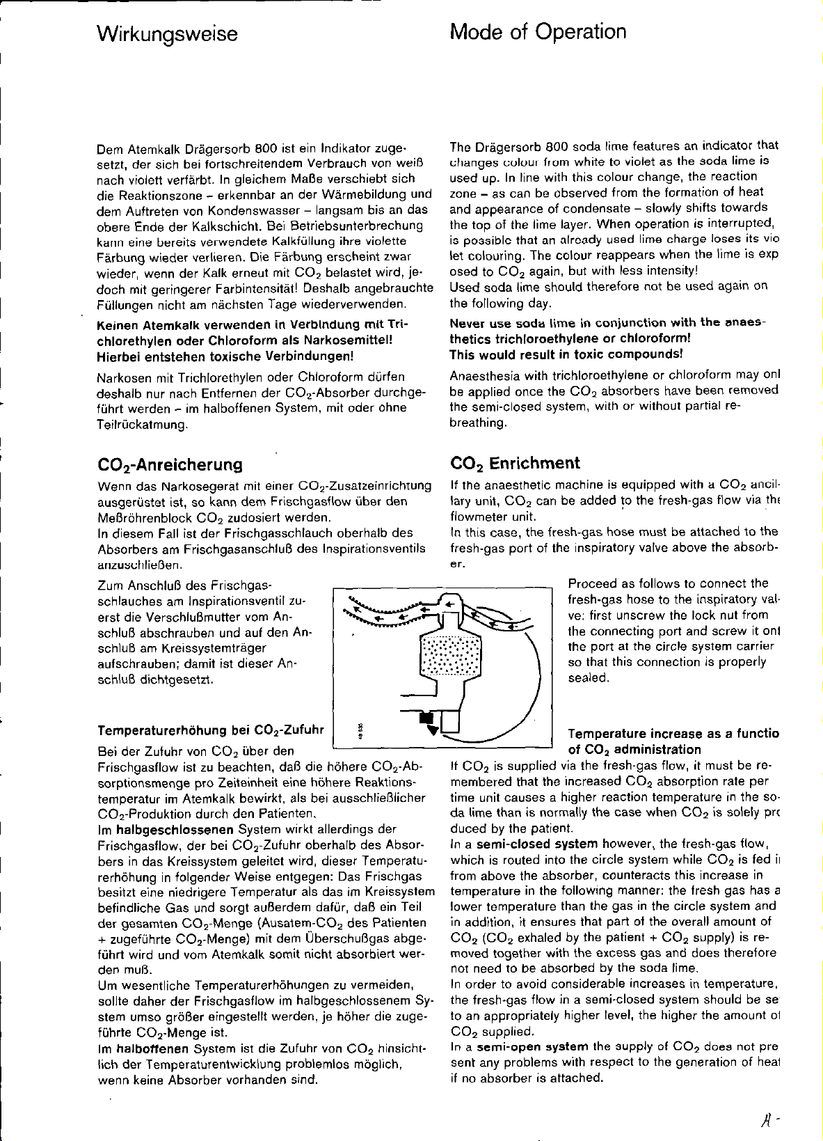
Proceed es follows to connect the
fresh-gas hose to the inspiratory valve: first unscrew the leck nut from
the connecting port and screw it onto
the port at the circle System carrier
so that this connection is properly
sealed.
Temperaturerhöhung bei CO+!ufuhr
Bei der Zufuhr von CO2 über den
Frischgasflow ist zu beachten, daß die höhere COS-Absorptionsmenge pro Zeiteinheit eine höhere Reaktionstemperatur im Atemkalk bewirkt, als bei ausschließlicher
C02-Produktion durch den Patienten.
Im halbgeschlossenen System wirkt allerdings der
Frischgasflow, der bei COg-Zufuhr oberhalb des. Absorbers in das Kreissystem geleitet wird, dieser Temperaturerhöhung in folgender Weise entgegen: Das Frischgas
besitzt eine niedrigere Temperatur als das im Kreissystem
befindliche Gas und sorgt außerdem dafür, daß ein Teil
der gesamten COS-Menge (Ausatem-CO, des Patienten
+ zugeführte CO,-Menge) mit dem Überschußgas abgeführt wird und vom Atemkalk somit nicht absorbiert werden muß.
Um wesentliche Temperaturerhöhungen zu vermeiden,
sollte daher der Frischgasflow im halbgeschlossenem Sy.
stem umso größer eingestellt werden, je höher die zugeführte CO*-Menge ist.
Im halboffenen System ist die Zufuhr von CO2 hinsichtlich der Temperaturentwicklung problemlos möglich,
wenn keine Absorber vorhanden sind.
Temperature increase es a function
of CO2 administration
If CO2 is supplied via the fresh-gas flow, it must be remembered that the increased CO2 absorption rate per
time unit causes a higher reaction temperature in the soda lime than is normally the case when CO? is solely pro-
duced by the Patient.
In a semi-closed System however, the fresh-gas flow,
which is routed into the circle System while CO* is fed in
from above the absorber, counteracts this increase in
temperature in the following manner: the lresh ges has a
lower temperatore than the ges in the circle System and
in addition, it ensures that part of the overall amount 01
CO2 (CO2 exhaled by the Patient + CO2 supply) is removed together with the excess gas and does therefore
not need to be absorbed by the soda lime.
In order to avoid considerable increases in temperature.
the fresh-gas flow in a semialosed system should be set
to an appropriately higher level, the higher the amount of
CO2 supplied.
In a semi-open system the supply of CO2 does not pre-
sent any problems with respect to the generation of heat
il no absorber is attached.
Page 10
Sicherheitsmaßnahmen
Safety Precautions
Vorschriften und Empfehlungen
Für Anwender in der Bundesrepublik Deutschland
gilt’):
Nach DIN 13252 und/oder MedGV müssen überwacht
werden
Atemwegsdruck*‘,
exspiratorisches Atemvolumen2’,
inspiratorische Sauerstoffkonzentration,
Narkosemittelkonzentration.
Unerwünschte Veränderungen dieser Parameter könne”
z.B. entstehen durch:
akute Zustandsänderungen des Patienten.
Gerätefehler, z.B. Lecks, Komponentenausfall, Ausfall
der Energie- oder Gasversorgung,
Bedienungsfehler.
Weiterhin sind im Geltungsbereich von DIN 13252 vor,
geschrieben:
Handbeatmungsvorrichtung
DIN 13252 fordert das Vorhandensein einer vom Beatmungs- oder Narkosegerät unabhängige” manuellen Be-
atmungsvorrichtung zur Sicherstellung der Ventilation des
Patienten mit Raumluft. Sollte bei einem erkennbaren
Fehler des Narkose-Beatmungsgerätes die lebenserhal.
Nur zum Draeger-internen Gebrauch. Gilt nicht als Gebrauchsanweisung!
tende Funktion nicht mehr gewährleistet sei”, muß unver-
züglich die Ventilation des Patienten mit der unabhängige”, manuellen Beatmungsvorrichtung aufgenommen
werden (z.B. Dräger-Resutator 2000).
Rules and Recommendations
Applicable for Users in the Federal Republic of Gev
many”:
In accordance with DIN 13252 a”d/ot the Regulations
Pertinent to Medical Engineering Equipment (MedGV),
the following must be monitored:
Airway pressure2!
Expiratory tidal volume’)
Inspiratory Oxygen concentration
Anaesthetics concentration.
Undesirable changes in these Parameters may, e.g, bt?
caused by:
Acute changes in Patient Status,
Equipment faults, e,g. leaks, failure of components,
failure of power 01 gas supply,
operating errors.
The following is also provided for the scope of DIN
13252:
Manual-ventilation bag
DIN 13252 provides that a manual Ventilation device must
be held available that is independent of the anaesthetic
machine or ventilator, in order to ensure ventilation of the
Patient with ambient air. Should a malfunction be detected in the anaesthesia ventilator o” account of which
its life-saving functions ca” no langer be maintained,
manual Ventilation of the Patient must be started immedi-
ately by means of the manual ventilation device (e.g.
Dräger Resutator 2000).
Narkosegasfortleitung
Unkontrolliertes Einatme” YO” Narkosemitteldämpfen ist
gesundheitsschädlich! Zum Schutz des OP-Personals
muß das dem Kreissystem und dem Narkosebeatmungs-
gerät entweichende Überschußgas entweder durch eine
Ejektoranlage abgesaugt oder durch Narkotikafilter eliminiert werden (siehe ,,Aufrüsten des Kreissystems”).
Schutz gegen elektrostatische Aufladung
Die einschlägige” Bestimmungen der Berufsgenossen-
schaft oder anderer nationaler Institutionen hinsichtlich
der Verwendung YO” elektrisch leitfähigen bzw. antistati.
sehen Gummi- oder Kunststoffteilen zur Verhütung YO”
Gefahren infolge elektrostatischer Aufladungen sind zu
beachte”.
Notwendigkeit der gleichzeitigen Druck- und Volumenüberwachung
Im Falle einer Diskonnektion eines Atemschlauches wird
bei automatischer Beatmung atmosphärische Luft über
Anaesthetic-gas scavenging System
Uncontrolled inhalatio” of anaesthetic vapours is injurious
to your health! The excess gas escaping from the circle
system and the anaesthesia Ventilator must therefore be
either scavenged via an ejector System, or eliminated by
means of an anaesthetics filter (cf. aaAssembly of the cir-
cle System”). in order to protect the surgical team.
Protection against electrostatic Charge
Attention must be paid to the regulations provided by Em.
ployers’liability Insurance Associations or other interna-
tional institutions concerning the use of electrically con-
ductive or anti-static rubber and plastic components, to
prevent the risks involved as a result ot electrostatlc
Charge.
The importante of simultaneous pressure and volume
monitoring
Should a breathing hose be inadvertently disconnected
during automatic ventilation, atmospheric air is drawn in
Page 11
Sicherheitsmaßnahmen ~ Safety Precautions
das Exspirationsventil angesaugt und vom Volumenmeß-
gerät angezeigt. Das während der Inspiration vom Beatmungsgerät transportierte Volumen entweicht über die
Diskonnektion (zwischen Inspirations- und ExspirationsVentil) und gelangt nicht zum Patienten. Die Volumenanzeige täuscht in diesem Fall ein Beatmungsvolumen nur
vor. Ein solcher Fehler ist nur durch ein Druckmeßgerät
erkennbar.
Bei Schlauchdiskonnektion während einer Spontanatmung atmet der Patient über die undichte Stelle atmosphärische Luft ein. Die Ausatmung erfolgt je nach Ort
der Diskonnektion ganz oder teilweise ins Freie. In diesem Fall wird das Volumenmeßgerät keinen oder einen
zu geringen Volumendurchsatz anzeigen und so auf die
Diskonnektion aufmerksam machen.
via the ewpiratory valve and indicated at the volume
meter. The volume conveyed by the ventilator during in-
spiration escapes via the disconnection (between inspiratory and expiratory valve) and does not resch the pa-
tient. Should this be the case, the volumeter merely
simulates a ventilatory volume and this in turn tan only be
detected by means of a pressure measuring instrument.
In the case of disconnection durihg spontaneous breath-
ing. the Patient inhales atmospheric air through the leak.
Depending on the location of disconnection, the exhaled
air is completely or partially discharged into the open.
Should this be the case, the volumeter displays no or in-
adequate volume throughput, thus indicating disconnection.
Nur zum Draeger-internen Gebrauch. Gilt nicht als Gebrauchsanweisung!
l
Empfohlene
Uberwachungsgeräte
Atemwegsdruck
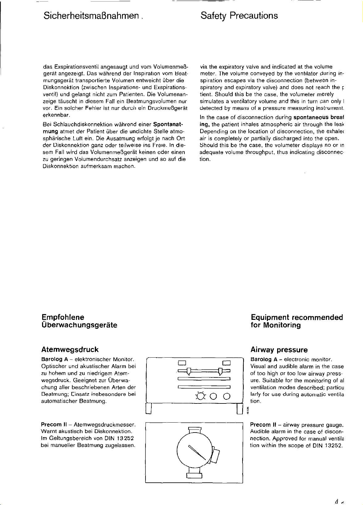
Barolog A - elektronischer Monitor.
Optischer und akustischer Alarm bei
zu hohem und zu niedrigem Atemwegsdruck. Geeignet zur überwachung aller beschriebenen Arten der
Beatmung; Einsatz insbesondere bei
automatischer Beatmung.
Precom II - Atemwegsdruckmesser.
Warnt akustisch bei Diskonnektion.
Im Geltungsbereich von DIN 13252
bei manueller Beatmung zugelassen.
Equipment recommended
for Monitoring
Airway pressure
Barolog A - electronie monitor.
Visual and audible alarm in the case
of too high or too low airway pressure. Suitable for the monitoring of all
Ventilation modes described; particularly for use during automatic ventilation.
Precom if - airway pressuro gauge.
Audible alarm in the case of disconnection. Approved for manual ventila-
tion within the scope of DIN 13252.
Page 12

Sicherheitsmaßnahmen
Safety Precautions
Atemvolumen
(exspiratorische Messung)
Volumeter 3000 oder Volumeter
2000 K (für Kinder).
Mißt Atemvolumen und Aiemminuten-
volumen.
Alternativ:
Spirolog 1N - elektronischer Volu-
men-Monitor.
Mißt Atemvolumen, Atemminutenvolu-
men und Atemfrequenz.
Optischer und akustischer Alarm bei
zu geringem und zu hohem Atemmi-
nutenvolumen.
Sauerstoffkonzentration
(inspiratorische Messung)
Nur zum Draeger-internen Gebrauch. Gilt nicht als Gebrauchsanweisung!
Oxydig - elektronischer Monitor.
Optischer und akustischer Alarm bei
zu niedriger (und zu hoher) 02-Konzentration.
Tidal volume
(expiratory measurement)
Volumeter 3000 or Volumeter 2000
K (for infants).
Measures both the tidal and minute
volume.
Alternatively:
Spirolog 1 N - electronie volume mo-
nitor.
Measures tidal volume, minute
volume and respiratory frequency.
Visual and audible alarm in the case
of too high or too low minute volume.
Oxygen concentration
(inspiratory measurement)
Oxydig - electronie monitor.
Visual and audible alarm in the case
of too low (and too high) OP concentratIon.
Narkosemittelkonzentration
(Messung im Frischgas)
Iris (oder Irina) - elektronische Moni-
tore.
Optischer und akustischer Alarm bei
zu hoher und zu niedriger Narkose-
mittelkonzentration.
DIrIrO
u
Anaesthetics concentration
(measurement in the fresh gas)
Iris (or Irina) - electronie monitors.
Visual and audible alarm in the case
of too high or too low anaesthetics
concentration.
Page 13

Kreissystem aufbauen
Assembly of
the Circle System
Das fabrikneue Kreissystem vor dem
ersten Einsatz sterilisieren oder desinfizieren (siehe LsPflege-, Seite 24).
Alle Sehraubverbindungen am
Kreissystem nur von Hand festdrehen. Keine Werkzeuge benutzen!
Die Dichtringe in den Schraubverbindurigen müssen vorhanden und
unbeschädigt sein.
Konusverbindungen vor dem Zusammenstecken prüfen, ob Oberflächen sauber (z.B. Kalkpartikel entfernen). Dichter Sitz wird durch
leichten Druck unter gleichzeitigem
Drehen erreicht.
Ventilteller und Führungsstifte im Inspirations- und Exspirationsventil prüfen, ob unbeschädigt. Die Führungsstifte dürfen nicht verbogen sein.
0 Kreissystemträger auf Zapfen am
Narkosegerät stecken und mit
Nur zum Draeger-internen Gebrauch. Gilt nicht als Gebrauchsanweisung!
Rändelschraube sichern.
A brand-new circle system must be
sterilised or disinfected Prior to initial
Operation (cf. &are~~ on page 24).
All screw connections of the circle
System may only be tightened by
hand. DO not use any tools!
Make sure that sealing rings arc pre.
sent in the screw connections and in
perfett condition.
Gone connections must be checked
for clean surfaces Prior to connection
(remove lime particles if required). A
proper fit is achieved by applying
slight pressure and twisting simultaneously.
Valve discs and guide pins in the in-
spiratory and expiratory valve must
be checked for proper condition.
The guide pins must be straight and
not bent.
l Place circle-ystem carrier onto the
pin of the anaesthetic machine
and secure by means of knurled
nut.
CO*-Absorber und Inspirationsventil
1 C02-Absorber mit frischem Atem-
kalk füllen und in den Aufnahmekonus des Kreissystemträgers
stecken.
2 Inspirationsventil in den Aufnah-
mekonus des COZ-Absorbers
stecken, Tülle nach links drehen.
3 Sehraubkappe vom Frischgasan-
schluß des Kreissystemträgers abschrauben und auf den Frischgasanschluß des Inspirationsventils
dicht aufschrauben.
Drucküberwachung
a) mit Atemwegsdruckmesser Pre-
com II
Im Geltungsbereich von DIN
13252 (BRD) ist Precom II nur für
die manuelle Beatmung zugelassen, Druckmesser ohne Alarmeinrichtung in keinem Fall.
4 Precom II an das Kreissystem an-
schrauben.
Gebrauchsanweisung Precom Il
beachten.
CO2 Absorber and
m
Inspiratory Valve
1 Fill CO? absorber with fresh soda
lime and place it onto the cone of
the circle-System carrier.
2 Push inspiratory valve into the
cone of the CO> absorber and
turn nozzle to the left.
3 Unscrew cap from the fresh-gas
port of the circle-System and
screw it tightly onto the fresh-gas
port of the inspiratory valve.
Pressure Monitoring
a) Using airway pressure gauge
Precom Il
Within the scope of DIN 13252
(e.g. West Germany), the Precom
It is approved for manual ventilation only; a pressure gauge without alarm facility is impermissible.
4 Screw Precom II to the circle sys.
tem.
Observe Instructions for Use of
Precom II.
Page 14

Kreissystem aufbauen
Assembly
b) mit Monitor Barolog A
5 Druckmeßanschluß an das Kreis-
system anschrauben.
6 Meßleitung an der Rückseite des
Barolog A anschließen.
Gebrauchsanweisung Barolog A
beachten.
Volumeter und Exspira-
tionsventil
7 Volumeter 3000 (oder 2000 K für
Kinder) auf den Druckmeßanschluß (oder auf Atemwegsdruckmesser) aufschrauben.
Gebrauchsanweisung Volumeter
Nur zum Draeger-internen Gebrauch. Gilt nicht als Gebrauchsanweisung!
beachten.
8 Exspirationsventil auf das Volu-
meter aufschrauben.
b) Using Barolog A monitor
5 Screw pressure-measurement
connection to circle System.
6 Attach measurement line to the
rear of Barolog A.
Observe Instructions for Use of
Barolog A.
Volumeter and
Expiratory Valve
Screw Volumeter 3000 (or 2000
K for infants) onto the pressuremeasurement connection (or onto
airway pressure gauge). Observe
Instructions for Use of Volumeter.
Screw expiratory valve onto Volumeter.
Alternativ:
Volumenüberwachung mit
Spirolog 1 N:
9 Sensorgehäuse mit Sensor anstel-
le des Volumeters aufschrauben,
dann
8 Exspirationsventil auf das Sensor-
gehäuse aufschrauben. Sensorkabel am Spirolog 1N einstecken.
Gebrauchsanweisung Spirolog
1 N beachten.
02-Überwachung
z.B. mit Oz-Monitor Oxydig
Den 0,.Sensor oberhalb des Inspirationsventils anbringen.
Hierzu werden folgende Teile benö-
tigt:
Kappe M 21 482,
Steckadapter M 27 964,
bestehend aus Unterteil und Oberteil
Alternatively:
Volume monitoring by means of
Spirolog 1 N:
Screw on sensor housing with
sensor instead of the Volumeter.
then
screw the expiratory valve onto
the sensor housing.
Attach sensor cable to Spirolog
1 N. Observe Instructions for Use
of Spirolog 1 N.
O2 Monitoring
e. g. by means of O2 monitor Oxydig.
Position the O2 sensor on top of the
inspiratory valve.
This requires the following compon-
ents:
Cap
Plug-in adapter
consisting of lower and upper section
M 21462
M 27964
Page 15

Kreissystem aufbauen
Assembly
0,.Sensor einbauen
Überwurfmutter vom Inspirationsventil losschrauben.
Schauglas entfernen und stattdessen
Kappe einsetzen. Überwurfmutter
wieder aufschrauben.
Unterteil des Steckadapters von
Hand fest in die Kappe einschrauben.
Oberteil des Steckadapters von
Hand fest auf den 0,.Sensor 5
schrauben.
O*-Sensor bis zum Anschlag in
die Kappe stecken.
01-Monitor Oxydig einbauen
6 Meßgerätehalter am Gelenkarm
festschrauben.
Nur zum Draeger-internen Gebrauch. Gilt nicht als Gebrauchsanweisung!
7 Oxydig aufstecke”.
0 Stecker des Sensorkabels in die
Buchse am Oxydig stecken.
n
Installation of O2 sensor
1 Unscrew cap nut from inspiratory
valve.
0 Remove siaht olass and fit
cep instead. Screw cap nut
o” again.
Firmly screw lower sectio” of
plug-in adapter into the cap by
band.
Firmly screw upper section of
plug-in adapter onto 0, sensor 5
by band.
Push 02 sensor into cap as far es
it will go.
Installation of 0, monitor Oxydig
6 Screw meter holder onto hlnged
arm.
7 Push Oxydig onto holder.
0 Plug sensor cable into socket on
Oxydig.
Atembeutel
An das Kreissystem sind anzuschlie-
ßen
1 Atembeutel, wen” die Narkose
nur in Spontanatmung durchge-
führt werden soll - ohne Beat-
mungsgerät.
1 Atembeutel mit
2 Verbindungstülle und
3 Faltenschlauch 1 m anschließe”,
wenn die Narkose in Spontanatmu”g und manueller Beatmung
durchgeführt werden soll - ohne
Beatmungsgerät.
kr
Breathing Bag
43
i-
1
The following components must be
attached to the circle system:
Breathing bag if anaesthesia is
performed during spontaneous
ventilation - without Ventilator.
6
UU
2
--r- -
TV
1
21
-
!rJ
3
Y’
/
-
P
l-
Breathing bag with
Cannecting socket and
Corrugated hose (1 m)
have to be attached if anaesthesia
is to be performed during spontaneous breathing and manual
ventilation - without ventilator.
Page 16

Kreissystem aufbauen
Zur Durchführung der Narkose mit
automatischer Beatmung - mit
Umschaltmöglichkeit auf manuelle
Beatmung oder Spontanatmung zusätzlich anschließen:
Pneumatisches Umschaltventil,
Verbindungsschlauch (Faltenschlauch) zum Beatmungsgerät
und
Steuerschlauch - zur Steuerung
des Umschaltventils bei Ein- und
Ausschalten des Beatmungsgerätes.
Narkose-Beatmungsgerät von
oräger:
Ventilog oder Alphavent.
0 Schläuche 5 und 6 anschließen.
Betrieb nach zugehöriger Ge-
brauchsanweisung.
Assembly
Ventilator
To perform anaesthesia with automat-
ic Ventilation - with possibility to
switch to manual ventilation 0r spon-
taneous breathing - the following
must be attached in addition:
4 Pneumatic switching valve,
5 Connecting hose (corrugated) to
the ventilator
plus
6 Control hose - to control the
switching valve during switch-onl
off of the Ventilator.
7 Anaesthesia Ventilator from
Dräger:
Ventilog or Alphavent.
0 Attach hoses 5 and 6.
Operation is performed in accordante with respective Instruchons
for Use.
Nur zum Draeger-internen Gebrauch. Gilt nicht als Gebrauchsanweisung!
Frischgasversorgung
8 Frischgasschlauch am Kreissy-
stemträger anschließen und wenn keine Narkosemittelüberwachung installiert ist - mit dem
Frischgasausgang des Narkosegerätes verbinden.
Anwender in der Bundesrepublik
Deutschland”:
Narkosemittelüberwachung installieren, z. 8. mit Monitor &is=
YO” Dräger.
9 Der Iris-Sensor wird bei den
meisten Dräger-Narkosegeräten
rückseitig am Gelenkarm des
Narkosegerätes befestigt (Anbrin-
gung durch DrägerService).
Verbindung mittels Frischgas-
8
schlauch vom Frischgasausgang
des Narkosegerätes über den
Iris-Sensor zum Kreissystemträger herstellen.
Sensorkabel am Narkosemittel-
10
monitor (z.B. Iris) anschließen
(zugehörige Gebrauchsanweisung beachten).
Fresh-Gas Supply
Attach fresh-gas hose to circlesystem carrier and - if no anaesthetics monitor is installed - to
the fresh-gas outlet of the anaes.
thetic machine.
For usw in the Federal Republit of Germany”:
Install anaesthetics monitor
e.g. “Iris‘ from Dräger.
With most Dräger anaesthetic
machines, the Iris sensor is attached at the war on the hinged
arm of the anaesthetic machine
(effected by DrägerService).
8 Route fresh-gas hose from
fresh-gas outlet of anaesthesia
ventilator via the Iris sensor to
the circle System carrier.
10 Attach sensor cable to anaes-
thetics rnonitor (e.g. Iris), observe respective Instructions for
Use.
J
.n .
Page 17

Kreissystem aufbauen
Assembly
Narkosegasfortleitung
Wen” eine Ejektoranlage vorhanden
ist:
. Absaugeschlauch auf die Tülle
unter dem Überdruckventil des
Kreissystems stecken.
Bild: Ansicht des Kreissystems
von hinten.
0 Wenn Beatmungsgerät vorhan.
den: zusätzlich Schlauch auf die
Abgastülle des Beatmungsgerätes stecken.
Nur zum Draeger-internen Gebrauch. Gilt nicht als Gebrauchsanweisung!
0 Schläuche mit T-Stück verbin-
den, Absaugeschlauch aufstekken.
0 Stecker des Absaugeschlauches
erst bei Narkosebetrieb in die
Kupplung der Ejektoranlage stekken.
Anaesthetic-Gas
Scavenging
If an ejector System is available:
l Attach scavenging hose to sock-
et underneath the relief valve of
the circle System.
Illustration: Rear view of circle
System
0 If a ventilator is available: fit an
additional hose to the scavenging
socket of the ventilator.
l Connect hoses with T-piece, fit
scavenging hose.
. DO not insert connector of
scavenging hose into the coupling
of the ejector System before com-
mencement of anaesthesia.
Wenn keine Ejektoranlage vorhanden
ist:
0 Narkotikafilter aufstecken.
If an ejector System is not availabe:
. Attach anaesthetic filters.
Page 18

Kreissystem aufbauen
Assembly
Atemschläuche
Isoclic-Verbindungen immer bis zum
Einrasten zusammenstecken. Lösen:
Flächen >>PRESS” zusammendrükken, isoclic von der Tülle ziehen.
Je einen Faltenschlauch 1 m auf
1 Inspirationsventil und
2 Exspiratio&entil stecken
und mit
3 Y-Stück verbinden.
Y-Stück mit der für den Patienten
notwendigen
4 Maske oder einem Katheteran-
schlußstutzen ausrüsten.
Wasserabscheider
Bei Enger dauernder Narkose ist
die Verwendung von
Wasserabscheidern empfehlens-
wert. Einbau zwischen je zwei Faltenschläuchen 0,5 m im Exspirations- und Inspirationszweig.
0 Die Wasserabscheider sollen sich
Nur zum Draeger-internen Gebrauch. Gilt nicht als Gebrauchsanweisung!
möglichst am tiefsten Punkt befin-
den, die Kondensatbehälter müs-
sen nach unten hängen.
0 Kondensatbehälter während des
Betriebs regelmäßig prüfen, bei
Bedarf entleeren. Hierzu Behälter
nach unten abziehen; ein selbstschließendes Ventil gewährleistet
Dichtheit des Systems.
l Beim Aufstecken des Behälters
auf festen. dichten Sitz achten.
Breathing Hoses
,&xxlic* connections must always be
pushed in until locked in Position.
Release: Press the areas marked
.PRESS together and pull isoclic off
the socket.
Push one corrugated hose each
of 1 m length onto
\nspiratory valve and
expiratory valve and connect
with
Y-piecs.
Fit a patient-specific
mask or catheter connector
to the Y-piece.
Water Separators
Use of
water separators is recommended for lang-term anaesthesia.
Installation in the expiratory arid
inspiratory branch is effected by
means of two corrugated hoses of
0.5 m each.
0 The water separators should be
positioned at the Ixest possible
Point, the condensate collectors
must ba suspended downwards.
l During operation, the condensate
collector must be checked regu-
larly and emptied if required. To
do so, remove collector by pulling
it downwards. A leak in the sys-
tem is prevented by a self-sealing
valve.
l When the collector is reattached,
make sure it makes a tight seal.
Mikrobenfilter (optional)
l Mikrobenfilter am Inspirationsventil
ninhxlen.
Mikrobenfilter nicht im Exspira-
tionszweig einbauen: Kondensat
kann den Strömungswiderstand
erhöhen und die Ventilation nachteilig beeinflussen. Gebrauchsanweisung “Mikrobenfilter* beachten!
Narkosegerät
nach eigener Gebrauchsanweisung
aufrüsten (z.B. Gasversorgung, Nx
kosemittelverdunster. Monitoring).
Microbial Filter (optionally)
i
:
0 Install a microbial filter at the in-
spiratory valve.
DO notfit the microbial filter into
the extpiratory branch: condensate is liable to increase the flow
resistance which in turn has an adverse effect on the ventilation. Observe the instructions for use of
the ,,Microbial Filter..
Anaesthetic Machine
assemble in accordance with appropriate instructions for use e.g. gas
supply, anaesthetics vaporizer, moni-
toring.
Page 19

Kurzprüfung
vor jedem Einsatz
Voraussetzung für den Einsatz des
Kreissystems am Patienten ist die
nach jeder Pflege (Reinigung, Desinfektion/Sterilisation) durchgeführte
Funktionsprüfung (s. Seite 28).
Unmittelbar vor jedem Einsatz folgende Kurzprüfung
gemäß “Checkliste für Inhalations-Narkosegeräte-,
durchführen:
English text: page 20
WAS
Narkosegas
Flaschenversorgung
Nur zum Draeger-internen Gebrauch. Gilt nicht als Gebrauchsanweisung!
Zentrale
Versorgung
Meßröhren
Narkosegasfortleitung
Narkotikafilter
02-Flush
fEvoass1
Vapor”
Sicherheitsfüllvorrichtung
Schalenfüllvorrichtung
Stecksystem
Vapor-
Umschalter
NarkosemittelMeßgerät
WIE SOLL
Flaschenventile öffnen
Steckkupplungen
einstecken
Dosierventile öffnen:
zuerst 02,
02 offen lassen,
dann N20
Steckkupplung Schauzeichen
einstecken grün
Filterzustand Filter erneuert
Schalter betätigen Flow vorhanden
Nullstellung
Füllung
Zeit seit letzter
Prüfung der
Konzentrationsabgabe
Zeit seit letzter
Inspektion
Verschlußschieber
Ventile
Verriegelung
Schalterstellung
Kalibrierung (Nullpunkt)
Funktionsprüfung
Druck 02
> 50 bar,
NzO > 30 bar
Schauzeichen
grün
Flow vorhanden
arretiert
ausreichend
1 Woche nicht
überschritten
%Jahr nicht
überschritten
(Prüfplakette)
eingeschoben
und festgezogen
geschlossen
Steckadapter
liegtgleichm.auf
verriegelt
Schalterstellung
richtig
durchgeführt
Funktion in
Ordnuna
WAS WIE
Beatmungsgerät
Atemkalk
Dichtheit für
halbgeschioss./
halboffenes
System
Überdruckventil
&-Meßgerät
Druck.Meßgerät
4olumen.
Meßgerät
jekretabiaugung
iandbeatnungsbeutelfür prüfen
‘Mbeatmung
Verbindungen zum
Kreissystem
Einschalten, Einstellungen ”
prüfen, bei Inspiration Beatmungsdruck
Y-Stück verschließen vorhanden
Schläuche
Atembeutel
Absorber
Volumeter
Volumeter-Heizung
Atemwegsdruckmesser
Meßanschlüsse
Ventilteller (Insp.+Exsp.)
Frischgasschlauch
Zustand der Füllung
Umschalter-Knebel
waagerecht, Y-Stück
mit Hand verschließen
Flow 0,2 L/min (ggf. mit
0,.Flush vorfüllen)
Umschalter senkr. nach
oben, Überdruckventil
‘20 mbar. Y-Stück ververschließen. Flow IOLlmin 20 f 5 mbar
Kalibrierung mit Luft durchgeführt
Kalibrierung (Nullpunkt)
Funktionsprüfung
Kalibrierung (Nullpunkt)
Funktionsprüfung Funktion in
Einschalten, Absaugeschlauch verschließen
Vollständigkeit
Beutel prüfen
SOLL
fester Sitz
Vollständigkeit
und fester Sitz
Kalk erneuert,
kein Farbumschlag
Druck 2 20 mbar
für 10 sec
Druckkonstanz
durchgeführt
Funktion in
Ordnung
durchgeführt
Ordnung
Unterdruck
vorhanden
vollständig
Funktion in
Ordnung
Page 20

Brief Check Prior
to each Use
The functional test (cf. page 28)
which is to be carried out whenever
the unit has been serviced (cleaning,
disinfection/sterilisation) is a mandatory for use of the circle system on a
Patient.
The following brief check must be carried out immediately Prior to each use, in accordance with the &heck List
for Inhalation Anaesthetic Machinesu.
This applies to “sers in West Germany. Please observe
the recommendations or regulations in forte in your
country.
i
What? How? Desired
Anaesthetic gas
Cylinder Open cylinder valves
S”PPlY
Pipeline
S”PPlY
Nur zum Draeger-internen Gebrauch. Gilt nicht als Gebrauchsanweisung!
Flowmeters
Aaesthetic gas
scavenging
system
Anaesthetic
filters
02.flush
(bypass)
Vapor” Zero setting
Safety filling
device
Vapor with
filling spout
Plug-in adapfer Connection
Selector switch Switch Position
Anaesthetics
mon,tor
Insert probes into Indicator green
terminal “nits
Open flow control valves:
first O2 (keep O2 open) Flow present
and then NzO
Insert probe into Indicator green
terminal “nit
Conditions of filters Filters replaced
Actuate switch Flow present
Level
Period since last
check af concentration release
Period since
last inspection
Plug
Valves of
filling spout
Locking lever
Zero calibration
Functional check
Pressure 02
> 50. N20
> 30 bar
Locked
Adequate
Not langer
than one
week
Not langer than
% year
(cf. check label
un lhe Vapur)
Inserted and
locked
Closed
Adapter evenly
located on
the socket
Locked
Switch setting
correct
Performed
Functioning
properly
Vhat?
\
lentilator
i
:ircle System
Soda lime
‘reedam from
eaks for semi,
:losed/semi>pen system
f
ielief valve Relief valve
32 rneter
‘ress”re gauge
,
/ol”me mete
Secretion
aspirator
Sag for manual
uentilation
(emergency
ventilation)
HOW?
Cannections to
circle system
Switch on, check
seffings, seal
Y-piece during
insDiration
HO?.lX
Reservoir bag
Absorber
Volumeter
Volumeter heating
Airway pressure
and gauge
Measurement
connections
Valve discs
(insp. and exp.)
Fresh-gas hose
Condition of time
Seal relief valve
and Y-piece, set
flow 0.2 Llmin
(use O2 flush if
deemed necessary
for the Start)
20 mbar. seal
Y-piece,‘flow
10 Llmin
Calibration with air
Zero calibration
Functional check
Zero calibration
Functional check
Switch on, seal
aspiration hose
Check completeness
Check bag
Desired
Tight
Airway pressure
present
Completeness
and tight fit
Lime renewed.
no colour Change
PreSSUre
> 20 mbar
for 10 seconds
Constant
pressure
20 + 5 mbar
Performed
Performed
Functioning
properly
Performed
Functioning
DrODerlV
1
Vacuum present
Complete
Functioning
properly
nn
Page 21

Narkosebetrieb
Anaesthesia
Narkoseführung
Die Narkoseführung erfolgt nach medizinischen und klinischen Erkenntnissen.
Das Kreissystem ist entsprechend der jeweiligen Betriebsart - wie im Kapitel ,,Wirkungsweise” (Seite 4) beschrieben - einzustellen.
Narkoseeinleitung
Bei der Narkoseeinleitung ist zu berücksichtigen, daß das
gesamte Atemsystem (Kreissystem, Beatmungsgerät und
Patient) noch nicht das gewünschte Atemgasgemisch
enthält. Das Ausspülen des anfänglich hohen Stickstoffanteils kann im halbgeschlossenen System mit relativ hohem Frischgasflow beschleunigt werden.
Wechsel der Betriebsart
Bei einem Wechsel von einer Betriebsart auf eine andere
(Spontanatmung, manuelle Beatmung, automatische Beatmung mit Druckbegrenzung am Kreissystem oder automatische Beatmung mit Druckreserve des Beatmungsgerätes) ist das Umschaltventil entsprechend umzuschalten.
Überdruckventil einstellen
Bei anmanueller Beatmung” und arautomatischer Beatmung
Nur zum Draeger-internen Gebrauch. Gilt nicht als Gebrauchsanweisung!
mit Druckbegrenzung am Kreissystems ist das über-
druckventil entsprechend der Compliance der Patienten-
lunge einzustellen.
Performance of Anaesthesia
Anaesthesia is performed in accordance with medical
and clinical knowledge.
The circle system is prepared in line with the individual
operating mode, as described in the section ,sMode of
Operation” (Page 4).
Induction of anaesthesia
For anaesthesia induction it must be remembered that
the entire breathing System (circle System, ventilator and
Patient) does not yet contain the desired breathing-gas
mixture. Flush-out of the initially high nitrogen content tan
be accelerated in the semi-closed System by a comparat-
ively high fresh-gas flow.
Changing the operating mode
When switching from one operating mode to the other
(spontaneous breathing, manual ventilation, automatic
ventilation with pressure limitation at the circle System or
automatic Ventilation with pressure reserve of the ventila-
tor), the switching valve must be changed accordingly.
Adjusting the relief valve
Where anmanual ventilation= and wwtomatic ventilation
with pressure limitation at the circle systemsc arc concerned, the relief valve must be set in accordance with
the compliance of the patient’s lungs.
Narkoseausleitung
Bei der Narkoseausleitung soll der Patient möglichst
rasch die aufgenommenen Narkosemittel - unter anderem
über die Lunge - wieder abgeben. Das ist nur möglich
bei einem entsprechenden Konzentrationsgefälle zwischen Patient und Kreissystem.
Knebel des Umschaltventils senkrecht nach oben stellen.
Überdruckventil auf niedrigen Druck einstellen.
Narkosemittelverdunster und N,O-Flow auf “0‘~.
Zur schnelleren Spülung Frischgasflow erhöhen.
Beatmungsgerät abschalten.
Patient manuell beatmen, einsetzende Spontanatmung
manuell unterstützen.
Wenn Spontanatmung vorhanden ist, Knebel des Umschaltventils senkrecht nach unten stellen.
Schnellentlüftung und Spülung
des Kreissystems
Zur schnellen Entlüftung des Kreissystems (um beispielsweise zu hohem Druckaufbau entgegenzuwirken, und zur
Spülung des Kreissystems während der Narkoseausleitung mit Hilfe des 0,.•ypasses am Narkosegerät) ist der
Knebel des Umschaltventils senkrecht nach unten zu
schalten. Der Druck wird dann sofort auf ca. 03 mbar
abgebaut. Das überschüssige Gas strömt über das Rückschlagventil in die Narkosegasfortleitung ab.
Termination of anaesthesia
During the wakeup period the anaesthetic absorbed
should be discharged by Patient via the lungs as soon as
possible. This tan only be, achieved with an appropriate
concentration gradient between the Patient and the circle
system.
Set toggle of switching valve to Point vertically upwards.
Set relief valve to low pressure.
Switch off anaesthetics vaporizer and N,O flow.
Increase fresh gas flow for rapid flushing.
Switch off the ventilator.
Effect manual ventilation, and assist commencing spontaneous breathing manually.
Once spontaneous breathing has re-established, set tog-
gle of switching valve to Point vertically downwards.
Rapid Venting and
Flushing of the Circle System
For rapid venting of the circle System (e.g. to counteract
an excessive pressure build-up, and for flushing the circle
System during the wake-up period by means of the O2
bypass at the anaesthetic machine) the toggle of the
switching valve must be set to Point vertically downwards. The pressure will thus be instantaneously reduced
to about 0.8 mbar. The~excess gas is discharged via the
unidirectional valve into the anaesthetic-gas scavenging
System.
Page 22

Narkosebetrieb
ri
ri
Verschlußkappe.-
Anaesthesia
Handhabung der C02-Absorber
Hinsichtlich der Handhabung sind
zwei Methoden anwendbar.
Verwendung von einem Absorber
Für die CO,-Absorption wird nur ein
Absorber im Kreissystem verwendet.
Ein zweiter mit frischem Atemkalk ge-
füllter Absorber befindet sich - mit
Kappe und Absorberfuß verschlossen - in Bereitschaft.
Ist der Atemkalk des verwendeten
Absorbers verbraucht, wird dieser
gegen den anderen bereitgestellten
Absorber ausgetauscht.
Der Austausch sollte dann vorgenommen werden, wenn
die Verfärbung des mit einem Farbindikator versehenen
Atemkalk Drägersorb 800 ca. zur Hälfte, spätestens aber
bis zu Q/s erfolgt ist. Der C02-Durchlaß beträgt dann ca.
0,5 bis 1 Vol.-% bei einem Atemminutenvolumen von
10 Llmin (20 x 0,5 L).
Bei diesen Angaben handelt es sich nur um Richtwerte”.
Stand-by absorber
Handling of the CO2
Absorbers
There arc two passible methods of
handling.
Use of one absorber
Only one absorber is used in the cir-
cle System for CO1 absorption. A second absorber, filled with fresh soda
lime and sealed by means of cap and
support, is kept on standby.
Once the soda lime in the first ab$ sorber is exhausted, it is replaced by
’ the standby absorber
Replacement should be effected when the colour indicator of the Drägersorb 800 soda lime reveals a colour
Change of about 50%, however at the latest once 2/3 arc
discoloured. Gien a minute volume of 10 Llmin (20 x 0.5
L). the CO? penetration rate amounts to approx. 0.5 to 1
vol.%. These figures arc reference values only’).
Nur zum Draeger-internen Gebrauch. Gilt nicht als Gebrauchsanweisung!
Verwendung von zwei Absorbern
Zwei Absorber werden hintereinandergeschaltet. Diese
Methode gewährleistet eine bessere Kalkausnutzung.
Handhabung (siehe Bild):
A Beide Absorber sind mit frischem Atemkalk gefüllt und
in das Kreissystem eingesetzt.
B Der untere Absorber verbleibt bis zur völligen Erschöp-
fung des Atemkalks im Kreissystem. Die weitere Ab-
sorption übernimmt der obere Absorber.
Use of two absorbers
Two absorbers arc switched in series which improves the
utilisation of Soda lime.
Handling (cf. illustration):
A Both absorbers arc filled with fresh soda lime and in-
stalled in the circle system.
B The lower absorber remains in the circle System until
its soda lime has been used up completely.
Further absorption is then assumed by the upper absorber.
Page 23

Narkosebetrieb
Anaesthesia
C Der untere Absorber ist herausgenommen worden, um
den verbrauchten Atemkalk zu beseitigen. Absorber
mit frischem Atemkalk füllen.
D Den frisch gefüllten Absorber als oberen Absorber
wieder einsetzen, um so den Atemkalk des unteren
Absorbers wieder voll ausnutzen zu können.
Weiterverwendung des Kreissystems
am nächsten Patienten
Sollen nach Beendigung der Narkose für den folgenden
Patienten lediglich die Atemschläuche, das Y-Stück und
die Maske bzw. der Katheteranschlußstutzen mit Katheter
ausgewechselt werden, so empfiehlt sich die Verwendung eines Mikrobenfilters zwischen Inspirationsventil
und Inspirationsschlauch (s. Seite 18).
Wurde zur vorangegangenen Narkose bereits ein Mikro-
benfilter benutzt, so ist dieses auszuwechseln und, sofern es nach der Kennzeichnung auf der Banderole noch
eine Sterilisation zuläßt, zu sterilisieren (s. Gebrauchsanweisung ,,Mikrobenfilter*c).
Atemkalk und Narkotikafilter können weiterbenutzt wer-
Nur zum Draeger-internen Gebrauch. Gilt nicht als Gebrauchsanweisung!
den, sofern noch ausreichende Absorptionsfähigkeit gegeben ist; Narkotikafilter nach Bstündigem Betrieb wechseln. Das Kreissystem ist wieder einsatzbereit.
C The lower absorber has been detached to remove
used soda lime. Fill absorber with fresh soda lime.
D Replace the newly filled absorber on top, so that the
soda lime contained in the lower absorber tan be
used UP to its full extent.
Repeated Use of the Circle System with
another Patient
If. following completion of anaesthesia, it is merely intended to exchange the beathing hoses, the Y-piece,
and the mask or the catheter connector with catheter, it
is recommended to make use of a microbial filter be-
tween inspiratory valve and inspiratory hose (cf.
page 18).
If a microbial filter was used for the previous anaesthesia,
this must be replaced and sterilised, provided the marking on the label still permits Sterilisation (cf. Instructions
for Use aaMicrobial Filterw).
Soda lime,and anaesthetic filters tan be re-used provided
their absorption capacity is still adequate.
The anaesthetic filters must be replaced after an 8.hour
operation. The circle System is ready for re-use.
Betriebsende, Entsorgung
Das Kreissystem kann nach Beendigung einer Narkose zusammen mit den mit Patientenluft in Berührung gekommenen Teilen des Beatmungsgerätes - zur Reinigung,
Desinfektion oder Sterilisation vom Narkosegerät entfernt of the ventilator that come into contact with the patient’s
werden.
Verbrauchter Atemkalk kann im Hausmüll entsorgt wer- normal hausehold garbage. Microbial filters which tan no
den. Nicht mehr sterilisierbare Mikrobenfilter und ver- langer be sterilised and used anaesthetic filters (following
brauchte Narkotikafilter (nach ca. 8.stündigem Narkosebetrieb) wie infektiösen Sondermüll entsorgen. waste.
Shutdown, Disposal
Following completion of anaesthesia, the circle System
tan be removed from the anaesthetic machine for cleaning, disinfection or sterilisation, together with those Parts
air.
Used Soda lime tan be disposed of together with the
approx. 8-hour operation) must be discarded as special
Page 24

Pflege
Care
Ein fabrikneues Kreissystem ist zur Keimfreimachung in
gleicher Weise zu behandeln wie ein benutztes Kreissystem. Aufgrund der vielfältigen Verfahren zur Reinigung,
Desinfektion und Sterilisation können hier nur grobe
Richtlinien und gezielt für die Behandlung des Kreissy-
stems zutreffende Hinweise gegeben werden. In jedem
Fall sind die Vorschriften der Hersteller von Reinigungsund Desinfektionsmitteln sowie die Vorschriften für spe-
zielle Reinigungs-. Desinfektions- und Sterilisationsverfah-
ren genau einzuhalten.
Kreissystem zerlegen
l Lösen der isoclic-Verbindungen: die Flächen nPRESS%
zusammendrücken und isoclic von der Tülle abziehen.
0 Alle Gummiteile (Atemschläuche, Maske, Atembeutel
usw.) vom Kreissystem abnehmen. Ebenso alle Meßgeräte (wie Oxydig, 02-Sensor, Volumeter usw.); diese Geräte behandeln, wie in den zugehörigen Gebrauchsanweisungen angegeben.
0 Kreissystem - wie im rechten Bild dargestellt - zerle-
gen.
l Im Inspirationsventil befindet sich ein Sieb 3.6 das
Nur zum Draeger-internen Gebrauch. Gilt nicht als Gebrauchsanweisung!
durch einen Sprengring 3.5 gehalten ist. Dieses Sieb
verhindert, daß Kalkstaub mit dem Atemgas über das
Inspirationsventil zum Patienten gelangt. Es kann zur
Reinigung durch Zusammendrücken des Sprengringes
herausgenommen werden. Zur Reinigung des Siebes
nur Bürsten mit Natur- oder Kunststoffborsten verwenden - keinesfalls Drahtbürsten oder andere harte
Werkzeuge!
Wir empfehlen, dieses Sieb mit dem Sprengring vor
der Desinfektion oder Sterilisation wieder einzubau-
en, um eine erneute Kontamination des Innenraumes
zu vermeiden. Das gleiche gilt für Dichtringe.
With respect to disinfection/sterilisation, a brandnew circle System must be treated as a used one. On account of
the numerous different methods of cleaning, disinfection
and sterilisation, the guidelines presented here arc very
rough only and pinpointed to the treatment of a circle
System. It is imperative to this end that the regulations
provided by manufacturers of cleaning and disinfecting
agents and rules pertinent to special cleaning, disinfecting and sterilisation procedures be strictly observed.
Disassembly of Circle System
l Release the isoclic connections: Press the areas
marked “PRESS< together and pull isoclic off the
socket.
l Remove all rubber components (breathing hoses,
mask, breathing bag etc.) from the circle System. Detach all measuring instruments (such as Oxydig, O2
sensor, Volumeter etc. Such equipment has to be treated as specified in their respective instructions for
use.
l Disassemble circle System as demonstrated in the
illustrations.
0 The inspiratory valve contains a filter 3.6 which is re-
tained by a snap ring 3.5. This filter prevents lime dust
from being passed to the patient with the breathing
gas via the inspiratory valve. lt tan be removed for
cleaning purposes by compression of the snap ring.
Only brushes with natura1 or plastic bristles may be
used for cleaning - never use wire brushes or pointed
took?.
We recommend to re-install the filter with snap ring
Prior to disinfection or Sterilisation to prevent a re-
newed contamination of the interior. The same applies
to all the sealing rings!
Alle Teile sorgfältig und schonend behandeln!
Während des gesamien Reinigungs-, Desinfekiions- und
Sterilisationsvorganges besteht für die Kreissysteme eine
erhöhte Beschädigungsgefahr! Beschädigungen an folgenden Teilen können zu Funktionsstörungen oder
Undichtheitert führen:
- Ventilkrater und Führungsstifte am Inspirations- und Exspirationsventil,
- alle Außen- und Innenkonen,
- untenliegende Dichtflächen an den Anschlußstutzen
des Exspirationsventils, Volumeters und Druckmessers,
- Hahnküken (Konus) des Umschaltventils 5,
- obere und untere Dichtfläche des Absorbermantels,
- Ventilkrater des Überdruckventils 6 im Kreissystemträger,
- alle Gewindeanschlüsse,
- obere Dichtfläche des Rückschlagventils 4.
All parts should be treated both gently and carefully!
During ihe entire process of cieaning, disinfection and
Sterilisation, there is an increased danger of circle-System
components being damaged. Darnage to the following
components is liable to cause malfunction or leaks:
- Valve seat and guide pins at inspiratory and expiratory
YaIVB,
- all male and fernale cones,
- lower sealing surfaces at connectors of expiratory val-
ve, Volumeter and pressure gauge,
- cone of switching valve 5,
- upper and lower sealing surface of absorber jacket,
- valve seat of relief valve 6 in circle-System carrier,
- threaded connections at fresh-gas ports of circle sys-
tem carrier and inspiratory valve,
- upper sealing surface of unidirectional valve 4.
Page 25

.Pflege
Care
Legende
t
Kreissystemträger
2 4 Absorberbode”
2.1
Spannmuttern
2.2 5 Absorberdeckel
2.3
Absorbermantel
3 6 Inspirationsventil.Gehäuse
3.1
Überwurfmutter
3.2
Schaukappe
3.3 Dichtring
3.4 Ventilteller
3.6 Sprengring Exsp.ventil
3.6 Sieb
3.7
Verschlußmutter
Rückschlagventil
Umschaltventil
Überdruckventil
6.1
überwurfschraube
7
Exspi,atio”sventil-Gehäuse
gleiche
Teile für
I
Insp: u.
I
K~Y
1
Circle system carrier
2
Absorber base
2.1 4 Tightening “uts
2.2
Absorber caver
2.3 5 Absorber jacket
3 Insp. MIVB housing
3.1 Cap nut
3.2 Sight glass
3.3 Sealing ring
3.4
Valve disc
3.5
Snap ring
3.6 Sieve lfilter)
3.7
Lack nut
Unidirectional valve
Changewer valve
6
Relief valve
6.1
Cap screw
7
Exp. valve housing
identical
patis lor
insp. and
exp. valve
I
3.2
,,
3.3
Nur zum Draeger-internen Gebrauch. Gilt nicht als Gebrauchsanweisung!
3.4
’ ‘...
,‘/
.-T
3.2
3.1
Inspirationsventd vollständig zerlegt
Inspiratory valve campletely disassembled
Vordesinfektion/Reinigung
Eine gründliche Reinigung ist unbedingte Voraussetzung
für eine erfolgreiche Keimfreimachung. Die Reinigung aller Teile des Kreissystems sollte mit einer Vordesinfektion verbunden sein.
Alle Teile 1-7 des Kreissystems, wie auch alle Gummiteile”, können in eine Desinfektionslösung gelegt werden.
Nach vorgeschriebener Einwirkzeit unter fließendem
Wasser rückstandsfrei reinigen. Zur Reinigung nur Etürsten mit Natur- oder Kunststoffborsten verwenden - keinesfalls Drahtbürsten oder harte Gegenstände!
Oberflächen der Teile mit einem Tuch abreiben, um Wasserflecke zu vermeiden.
Die gereinigten Teile trocknen, um Keimwachstum und
Korrosion weitestgehend zu vermeide”.
DisinfectionKleaning
Thorough cleaning is imperative for proper disinfectiow
sterilisatio”. Cleaning of all circle System components
should be linked to a preliminary disinfection.
All components l-7 of the circle System, plus all rubber
parts”. ca” be placed in a disinfecting solution. After the
prescribed reaction time they have to be thoroughly
rinsed under running water to remove all residues. Only
use brushes with natura1 or plastic bristles for cleaning,
never use wire brushes or hard objects!
Dry the surfaces of Parts concerned with a cloth to avoid
water spots.
All components must be dried after cleaning to prevent
bacterial growth and corrosion to the greatest possible
extent.
Page 26

Pflege
Care
Dräger bietet verschiedene Einrichtungen zur Reinigung,
Trocknung und Desinfektion an:
- Dräger-Spüleinrichtung 2M 8215 für Atemschläuche,
Atembeutel usw.
- Dräger-Reinigungspistole 2M 15 138, insbesondere für
schlecht zugängliche Teile wie Tuben, Katheter usw.
- Dräger-Trockeneinrichtung 2M 8220, insbesondere für
Atemschläuche und Volumeter.
- Trockenschrank TS 9000 mit großer Aufnahmekapazität,
- ANDA Wach- und Desinfektionsautomaten (verschiedene Modelle) mit integrierter Trocknung.
- Dräger-Purfactor, eine vollautomatische Wach- und
Desinfektionsmaschine für Anästhesie- und ChirurgieZubehör, zum Waschen, Desinfizieren, Spülen und
Trocknen.
Desinfektion/Sterilisation
Wenn das nach der Reinigung und Trocknung folgende
Desinfektions- oder Sterilisationsverfahren es zuläßt, sind
die Teile des Kreissystems in Baugruppen oder vollständig zusammengebaut zu behandeln (siehe Jusammenbaw).
Nur zum Draeger-internen Gebrauch. Gilt nicht als Gebrauchsanweisung!
Für eine Heißdampfsterilisation bei 134°C im Autoklaven
können beispielsweise die einzelnen Funktionselemente
wie Inspirationsventil, Exspirationsventil, Absorber und
Kreissystemträger mit Überdruckventil, Umschaltventil
und Rückschlagventil zusammengebaut werden, ohne
daß der Sterilisationserfolg darunter leidet.
Das Hahnküken des Umschaltventils 5 ist vor jeder
Desinfektion oder Sterilisation mit Silikonfett einzufetten,
wenn die Desinfektion oder Sterilisation in zusammengebautem Zustand erfolgt (siehe “Zusammenbau“).
Der Zusammenbau vor der Desinfektion oder Sterilisation
hat den Vorteil, daß eine erneute Kontamination des Innenraums mit Keimen im Anschluß an die
Desinfektion/Sterilisation sicher vermieden wird. Andernfalls ist beim Zusammenbau desinfizierter oder sterilisierter Einzelteile besondere Sorgfalt notwendig.
Eine Heißdampfsterilisation bei 134°C ist mit allen auf
Seite 25 da:ges!e!!ten Tcilcr; möglich.
Drägerwerk AG holds a variety of equipment available to
facilitate cleaning, drying and disinfection:
- Dräger Rinsing Unit 2M 8215 for breathing hoses,
breathing bags etc.
- Dräger Cleaning Gun 2M 15138, especially for Parts
which arc not readily accessible such as tubes, catheters etc.
- Dräger Drying Unit 220, especially for breathing hoses
and Volumeters
- TS 9000 large-volume Drying Cabinet
- ANDA the automatic washing and disinfection machine
(various models) with integrated drying facility.
- Dräger Purfactor. a fully automatic washing, disinfection rinsing and drying machine for anaesthetic and
surgical accessories.
DisinfectionKterilisation
If, following cleaning and drying, subsequent disinfection
or sterilisation procedures permit, components of the circle System tan be treated completely assembled or in
sub-assemblies (cf. “Assemblyx).
For Sterilisation in superheated steam at 134°C in an
autoclave, the individual components such as inspiratory
valve, expiratory valve, absorber, circle system carrier
with relief valve, switching valve and undirectional valve
tan be assembled without Sterilisation being adversely af-
fected.
The cone of switching valve 5 must be lubricated with si-
licone grease Prior to each disinfection or Sterilisation if it
is subjected to this procedure in assembled state (cf.
~~Assembly~~).
Assembly Prior to disinfection and sterilisation has the
advantage that renewed contamination of the interior is
reliably precluded. Otherwise, particular care must be
taken when disinfected or sterilised components arc assembled.
All the components listed on page 25 tan be subjected
to Sterilisation in superheated steam at 134%.
Behandlung von Gummiteilen
Gummiteile wie Schläuche, Masken, Atembeutel und Ka-
theter sind, wie beschrieben, zu reinigen.
Bei Ballonteilen, wie Intubationskathetern und Atemmasken, muß der Ballon vor der Reinigung sorgfältig entlüftet
und danach wieder verschlossen werden, damit eine
Überdehnung des Ballons durch Wärmeeinwirkung vermieden wird, andererseits aber auch keine Flüssigkeit
eindringen kann. Vor einer Heißdampfsterilisation ist dagegen der Ballon zu öffnen, um ein Platzen bei der Evakuierung des Autoklaven zu verhindern.
Treatment of Rubber Parts
Rubber Parts such as hoses, masks, breathing bag and
catheter must be cleaned as described.
Where Parts arc concerned which incorporate a cuff,
such as intubation catheters and beathing masks, the
cuff must be carefully vented Prior to cleaning and then
sealed again, in order to prevent werexpansion caused
by the effect of heat on the one band, and liquid from en-
tering on the other. For Sterilisation in superheated steam
however, the cuff has to be opened to prevent it from
bursting when the autoclave is evacuated.
Page 27

Nur zum Draeger-internen Gebrauch. Gilt nicht als Gebrauchsanweisung!
Page 28

Funktionsprüfung
Functional Test
Nach jeder Pflege des Kreissystems
(Reinigung, DesinfektionlSterilisation,
Zusammenbau) muß eine FunkiionsPrüfung durchgeführt werden.
Prüfung am Prüfgerät
Der speziell für das Gerätepflegezentrum entwickelte Dräger-Geräteprüfstand GPS 3000 ermöglicht eine
schnelle und bequeme Überprüfung
des Kreissystems durch Meß- und Si-
mulationsvorgänge. Der Ablauf der
Prüfung ist auf einer dem Prüfstand
beiliegenden Prüfliste festgelegt.
Falls der Geräteprüfstand GPS 3000
nicht zur Verfügung steht, ist nach
nPrüfung am Narkosegerät” zu ver-
The functional test must be performed after each servicing procedure (cleaning, disinfectionlsterilisation, assembly) on the circle
system.
Testing with Tester
The Dräger test bench GPS 3000
which has been especially developed
for use in the equipment maintenance
centre facilitates rapid and convenient testing of the circle System by
way of measurement and Simulation
procedures.
Should the GPS 3000 not be available, the test tan be carried out in
accordance with “Testing on the
Anaesthetic Machirw.
Nur zum Draeger-internen Gebrauch. Gilt nicht als Gebrauchsanweisung!
Prüfung am Narkosegerät
Kreissystem mit Narkosegerät betriebsbereit zusammenstellen (mit
Atemwegsdruckmesser, Volumeter,
O&ensor, frisch gefüllten Absorbern, usw.). Dadurch werden bei der
Prüfung alle evtl. vorhandenen Undichtheiten erfaßt, die beim nachträg-
lichen Komplettieren nicht mehr er-
kannt werden könnten. Die
Verwendung eines Atemwegsdruck-
messers ist für die Prüfungen Vor-
aussetzung.
1 Frischgasschlauch - vom Narko-
segerät kommend - am Kreisaystem anschließen.
0 Faltenschläuche - wie dargestellt
- aufstecken und
‘2 am Y-Stück zusammenführen.
Dichtheitsprüfung
3 Knebel des. Umschaltventils waa-
gerecht stellen.
0 An der 02.Meßröhre des. Narko-
segerätes Flow 0,5 L/min einstellen (ggf. mit O?-Flush vorfüllen).
l Druck am Atemwegsdruckmesser
muß auf > 40 mbar ansteigen.
Testing on the
Anaesthetic Machine
Assemble the circle system ready for
use with anaesthetic machine (includ,
ing airway pressure gauge, Valumeter, O2 sensor, newly filled absorbers, etc.). This test reveals all
possible leaks which could not be
detected in the case of subsequent
fitting. Use of an airway pressure
gauge is mandatory for the test.
1 Attach fresh gas hose from anaes~
thetic machine to circle system.
0 Attach breathing hoses as illus-
trated and
2 jein them at the Y-piece.
Leak test
3 Set toggle of swtiching valve to
horizontal Position.
l Adjust a flow of 0.5 Llmin at the
O2 flowmeter of the anaesthetic
-Ii
machine.
l The pres~re at the airway p~ss-
ure gauge must rise to more than
40 mbar (use O2 flush for pre-fill-
ing if required).
Page 29

Funktionsprüfung Functional Test
Prüfung des Überdruckventils
r
l Die gezeigte Prüfanordnung bei-
behalten.
3 Knebel des Umschaltventils senk-
recht nach oben stellen.
4 Einrichtung zur Narkosegasfortlei-
tung anschließen und in Betrieb
setzen (Ejektor-Absaugeanlage).
0 Gesamtgasmenge (0, und N,O)
an den l&sierventilen des Narkosegerätes auf 20 Llmin einstellen.
5
Überdruckventil zunächst auf 20
mbar und anschließend auf 40
mbar einstellen. Die am Atemwegsdruckmesser abgelesenen
Druckwerte mit den eingestellten
Werten vergleichen. Die Abweichung darf i- 15% betragen (20 f
3 mbar bzw. 40 + 6 mbar).
Prüfung des Rückschlagventils für
Nur zum Draeger-internen Gebrauch. Gilt nicht als Gebrauchsanweisung!
Spontanatmung
0 Die Prüfanordnung bleibt unverän-
dert.
3 Umschaltventil auf Stellung Spon-
tanatmung (Knebel senkrecht nach
unten) schalten.
4 Narkosegasfortleitung bleibt an
der Ejektor-Absaugeanlage angeschlossen.
0 Gesamtgasmenge (0, und N,O)
an den Dosierventilen des Narkosegerätes auf 10 Llmin einstellen.
Der Druck darf min. 0 mbar, max.
2 mbar betragen (die Ablesung
am Druckmesser ist zu schätzen).
Bei deutlich höherem Druck ist die
Bohrung im Umschaltventil auf
den freien Querschnitt hin zu
überprüfen. Unter Umständen ist
das Rückschlagventil auszuwechseln.
Bei deutlich geringerem Druck ist
die Narkosegas-Absaugeanlage zu
überprüfen. Am Rückschlagventil
darf kein Unterdruck entstehen,
der das Ventil öffnen würde.
Bei der Dräger-Ejektor-Absaugeanlage sind zur Vermeidung von
Unterdruck Belüftungsbohrungen
in der Anschlußmuffe des Absaugeschlauches vorhanden.
r
Testing the relief vaive
Test setup is maintained as illus-
l
trated.
3
Set toggle of switching valve to
Point vertically upwards.
4
Attach anaesthetic gas scavenging System and activate it (ejector System).
l
Adjust an overall gas volume (0,
and N,O) of 20 L/min at the flow
control valves of the anaesthetic
machine.
5
Set relief valve initially to 20 mbar
2nd then to 40 mbar. Compare
the reading at the airway pressure
gauge with the set values. The de-
viation should not exceed ? 15%
(20 i3 mbar or 40 f-6 mbar).
Testing the unidirectional valve for
spontaneous beathing
l The test setup remains un-
changed.
3 Set switching valve to spontan-
eous breathing (toggle pointing
vertically downwards).
4 Anaesthetic gas scavenging sys-
tem remains attached to ejector
System.
l Adjust an overall gas volume (0,
and N,O) of 10 Llmin at the flow
control valves of the anaesthetic
machine. The minimimum pressure
should be 0 mbar, maximum
pressure 2 mbar (the reading on
the airway pressure gauge has to
be estimated). Should the pressure be distinctly higher, the hole in
the switching valve must be
checked for a free cross section.
If required, the unidirectional valve
must be replaced.
Should the pressure be distinctly
lower, the anaesthetic gas scavenging System must be checked.
There must be no negative pressure that would open the unidirectional valve.
The Dräger ejector-type extraction
System provides vent holes in the
connecting sleeve of the extraction hose to prevent such negative
pressure.
/7
Page 30

Funktionsprüfung
Functional Test
Funktionsprüfung des Inspirationsund des Exspirationsventils
Prüfanordnung wie dargestellt aufbauen:
6 Handbeatmungsbeutel am Kreissy-
stemträger anschließen und
7 einen Atembeutel am Maskenko-
nus des Y-Stückes aufstecken.
Sichtkontrolle des
9 Inspirationsventils und des
9 Exspirationsventils:
Ventilteller vorhanden und unbeschädigt, Führungsstifte rund um
die Ventilteller vollzählig und nicht
verbogen.
3 Knebel des Umschaltventils senk-
recht nach oben stellen.
0 Kreissystem mit O2 auffüllen, bis
Handbeatmungsbeutel und Beutel
am Y-Stück etwa auf 5 mbar gebläht sind. Dann Dosierventil für
O2 schließen.
l Handbeatmung durchführen, Ven-
tilteller beobachten: Ventilteller im
Nur zum Draeger-internen Gebrauch. Gilt nicht als Gebrauchsanweisung!
Inspirationsventil soll nur während
der Inspiration abheben, Ventilteller im Exspirationsventil soll nur
während der Exspiration abheben.
l Volumeter beobachten: Schon ein
geringfügiger Rückwärtslauf wäh-
rend der Inspirationsphase weist
auf einen Defekt im ExspirationsVentil hin.
Functional test of inspiratory and
expiratory valves
Establish test setup as illustrated:
6 Attach bag for manual ventilation
at the circle System carrier and
7 attach breathing bag to mask
cone of the Y-piece.
Visual check of
6
Inspiratory valve and
9
Expiratory valve:
Valve discs available and undamaged, guide pins along valve disc
complete and not bent.
3
Set toggle of switching valve to
Point vertically upwards.
Fill circle System with 0, until the
0
bag for manual ventilation and the
bag at the Y-piece arc inflated to
roughly 5 mbar. Then close O2
flow control valve.
l
Perform manual ventilation and
_I
ObSelw valve dlSC CIISC 1” In-
spiratory valve should only lift off
during inspiration, valve disc in ex-
piratory valve should lift off during
expiration only.
0 Observe Volumeter: wen a slight
reverse movement during inspiration Phase indicates that the expiratory valve is defective.
Abschlußprüfung
Nach Abschluß der Prüfungen das
Kreissystem funktionsgerecht für den
Narkoseeinsatz herrichten:
0 Alle Schlauchverbindungen prü-
fen.
l Absorberfüllung prüfen.
l Kreissystem an das vorgesehene
Beatmungsgerät (z.E. Ventilog
oder Alphavent) anschließen.
Final test
Following completion of tests, pre-
pare circle System as for actual use
in anaesthesia.
l Check all hose connections.
0 Check absorber Charge.
0 Attach circle System to envisaged
Ventilator (e.g. Ventilog or Alphavent).
Page 31

Instandhaltungsintervalle Maintenance Intervals
Definitionen nach DIN 31051:
Inspektion = Feststellen des Ist-Zustandes
Wartung = Maßnahmen zur Bewahrung des
Soll-Zustandes
Instandsetzung = Maßnahmen zur Wiederherstel-
lung des. Soll-Zustandes
Instandhaltung = Inspektion, Wartung, ggf.
Instandsetzung.
Das Kreissystem muß halbjährlich Inspektionen und War-
tungen durch Fachleute unterzogen werden - mit Proto-
koll. Der Abschluß eines Service-Vertrages mit dem Drä-
gerService wird empfohlen.
Instandsetzungen am Kreissystem -soweit sie über den
Austausch von Teilen hinausgehen - nur durch den
DrägerService.
Für die Instandhaltung nur Original-Dräger-Teile verwenden.
Gerät bzw. Geräteteile vor jeder Instandhaltungsmaßnahme - auch bei Rücksendung zu Reparaturzwecken
- reinigen und desinfizieren!
Definitions in accordance with DIN 31051:
Inspection
Service
= examination of actual condition
= measures to maintain specified
condition
Repair
= measures to restore specified
condition
Maintenance
= inspection, service and,
if applicable, repair.
Every sin months, the circle System must be subjected to
inspection and service by experts (and a record kept).
lt is recommended to enter into a service contract with
DrägerService.
Repairs on the circle System, insofar as they go beyond
the replacement of components, may only be effected by
DrägerService.
Only original Dräger spare Parts may be used for repair.
Circle Systems or parts of them must be cleaned and
disinfected Prior to maintenance and especially Prior
to returning them for repair.
Nur zum Draeger-internen Gebrauch. Gilt nicht als Gebrauchsanweisung!
I
Abmessungen
Gewicht
Widerstand
zwischen Atembeutelanschluß
und Y-Stück (Kreissystem
komplett, incl. Schläuche,
Y-Stück, zwei gefüllte
Absorber. Umschaltventil
geschlossen)
- inspiratorisch < 3 mbar bei 60 Llmin
- exspiratorisch
Compliance < 70 mL bei 20 mbar
(Kreissystem komplett, < 140 mL bei 40 mbar
incl. Schläuche, Y-Stück, zwei
gefüllte Absorber. jedoch
ohne Atembeutel)
Widerstand
ges vollständig geöffnete”
Uberdruckventils
Absorber-Widerstand
(zwei gefüllte Absorber)
Absorber-Compliance
(zwei gefüllte Absorber) < 64 mL bei 40 mbar
Absorber-Volumen je 1 Liter
Widerstand
- Inspirationsventil
Exspirationsventil
- Rück>chlagventil <
(zur UberschuBgasableitung
bei Spontanatmung am Ende
der Exspiration)
siehe Abbildung umseitig
6,2 kg
< t,6 mbar bei 30 L/min
< 2.3 mbar bei 60 Llmin
< 1 mbar bei 30 L/min
< 16 mbar bei 60 Llmin
< 4 mbar bei 30 Llmin
< 1 mbar bei 60 Llmin
< 42 mL bei 20 mbar
< 0.5 mbar bei 20 L/min
< 0.5 mbar bei 20 Llmin
1 mbar bei 20 L/min
Dimensions
Weight 6.2 kg
Resistance
between breathing-bag
connection and Y-piece (circle
system complete, incl. tubes,
Y-piece. two filled absarbers,
switching valve closed)
- Insplratoiy
- expiratory
Compliance
(circle system complete,
incl. tubes, Y-piece, two
filled absorbers, yet without
breathing bag)
Resistance
of the completely opened
reliei valve
Absorber resistance
(two filled absorbers)
Absorber compliance
(two filled asorbers)
Absorber volume
Resistance
- mspiratory valve
- expiratory valve
- unidirectional valve
(for excess-gas exhaust
during spontaneous breathing.
at the end of expiration)
sec drawing (p.t.0.)
< 3 mbar at 60 Llmin
< 1.5 mbar at 30 Llmin
< 2.3 mbar at 60 Llmin
< 1 mbar at 30 Limin
< 70 mL at 20 mbar
< 140 mL at 40 mbar
< 16 mbar at 60 Llmin
< 4 mbar at 30 Llmin
< 1 mbar at 60 Llmin
< 42 mL at 20 mbar
< 64 mL at 40 mbar
1 litre each
< 0.5 mbar at 20 Llmin
< 0.5 mbar at 20 Llmin
< 1 mbar at 20 Llmin
Forts. umseitig
Page 32

,Technische Daten (Forts.)
Technical Data (continued)
Tüllen-Nenndurchmesser
für Atemschläuche Kreissystem 8 ISO und
Durchmesser für
Abgastülle
Atembeutelvolumen 2,3 L
(andere Größen sind
lieferbar)
Atemschlauchlänge Irr
Frischgasanschluß-Gewinde
maximale Undichtheil
(ohne Volumeter)
22 mm ISO-Konen (für
Kreissystem 6 isoclic)
27 mm
M16xl,5rnrn
0,2 Llmin bei 40 mbar
(ca. O,O5 Llmin bei IOmbar
Diameter of connection
sockets far breathing tubes
Diameter of
exhaust-gas socket
Ereathing-bag volume
(other volumes an request)
Length of breathing tubes
Fresh-gas cannection (thread) M 16 x 1.5 mm
Maximum leak rate
(without Volumeter
_
Nur zum Draeger-internen Gebrauch. Gilt nicht als Gebrauchsanweisung!
22 mm ISO tapers (for
Circle System 8 ISO and
Circle System 6 isoclic)
27 mm
2.3 L
Im
0.2 Llmin at 40 mbar
(approx. 0.05 Llmin
at 10 mbar)
Bestell-Liste
Benennung
Kreissystem 6 ISO
Kreissystem 6 isoclic
Kreissystem 7a
Drägersorb 600 (Atemkalk)
5-Liter-Behälter
IO-Liter-Behälter
50.Liter-Behälter
Bestell-Nr.
M 25 690
M26211
M 23 074
67 50 701
67 60 901
6752001
Order List
Denomination
Circle system 8 isoclic M 26211
Circle system 7a M 23 074
Circle system 8 ISO M 26 690
Drägersorb 600 (Soda lime)
5 litres container
10 litres container
50 litres container
Code no.
67 50 701
67 50 601
67 52 001
I
I
Page 33

Teile-Liste
r
Parts List ‘-.
Nur zum Draeger-internen Gebrauch. Gilt nicht als Gebrauchsanweisung!
Page 34

Nur zum Draeger-internen Gebrauch. Gilt nicht als Gebrauchsanweisung!
Page 35

Teile-Liste (Fortsetzung)
8
9
-
Parts List (coniinued)
Sa.2 Überwurfmuttern
Nur zum Draeger-internen Gebrauch. Gilt nicht als Gebrauchsanweisung!
Sealing ring
2,
22
23
Absorber
24
25
-
-
-
-
22
23
17
18
19
20
21
22
23
24
25
113230
-
26
27
2s
-
26
27
28
-
Page 36

Diese Gebrauchsanweisung gilt für alle
Kreissysteme 6 ISO, 8 isoclic und 7a.
deren Inspirations- und Exspirationsventi.
le eine Fabrikationsnummer enthalten, jsdoch keine weitere Kennzeichnung unter
der Fabrikationsnummer.
These Instructions for Use apply to all
Circle Absorption Systems 6 ISO/6 isoclicl7a whose inspiratory and expiratory
valves bear a serial number. howwer, not to those bearing a sub numer
below the serial number.
Drägerwerk
Aktiengesellschaft
__ _ -.
Postfach 1339
Moislinger Allee 53-55
2400 Lübeck 1
Telefon (0451) 682.0
Telex 26807.0
Telefax (0451) 682-2080
Niederlassungen
und Verkaufsbüros
Nur zum Draeger-internen Gebrauch. Gilt nicht als Gebrauchsanweisung!
Bad Ems
Telefon (02603) 3065
Telex 869011
Berlin
Telefon (030) 250096-0
Telefax (030) 25009641
Bielefeld
Telefon (0521) 52079-0
Telefax (0521) 5207979
Bremen
Telefon (0421) 48602-0
Telefax (0421) 46602 11
ESS.3”
Telefon 1020541 104-0
Telefax (02054j 104106
Kassel
Telefon (0561) 21099
Telex 99542
Kiel
Telefon (0431) 91231 . ..34
Telefax (0431) 93756
Köln
Telefon (0221) 17909.0
Telefax (0221) 1790910
Krefeld
Telefon (02151) 4409.0
Telefax (021 51) 440916
München
Telefon (069) 61007-0
Telefax (089) 6 100771
Drägerwerk
Aktiengesellschaft
Lübeck
Federal Republic of Germany
= Postfach 1339
e Moislinger Allee 53-55
D-2400 Lübeck 1
%e (451) 662-0
q 26607-0
FAX (451) 662-2060
Hamburg
Telefon (040) 363421
Telefax (040) 362561
HannOVef
Telefon (0511) 45605-0
Telefax (05 11) 4580560
Karlsruhe
Telefon (07243) 7745-0
Telefax (07243) 774577
GA 5371 dla . 90 27 772
Q Drägerwerk Aktiengesellschaft
5. Ausgabe September 1969
Anderurigen vorbehalten
Nürnberg
Telefon (09 11) 56604-0
‘I’eletax 1uQ I i j 5660455
Saarbrücken
Telefon (0661) 61277...79
Telefax (0661) 63405
Stuttgart
Telefon (07 11) 7 1502-0
Telefax (07 11) 7 2693 17
Wiesbaden
Telefon (061 22) 509.0 ’
Telefax (06122) 509 19 B
GA 5371 die .90 27 772
0 Drägerwerk Aktiengesellschaft
5th edition September 1969
Subject to alteration
 Loading...