

NORTH AMERICAN DRÄGER Cato User manual
I) Block Diagram:
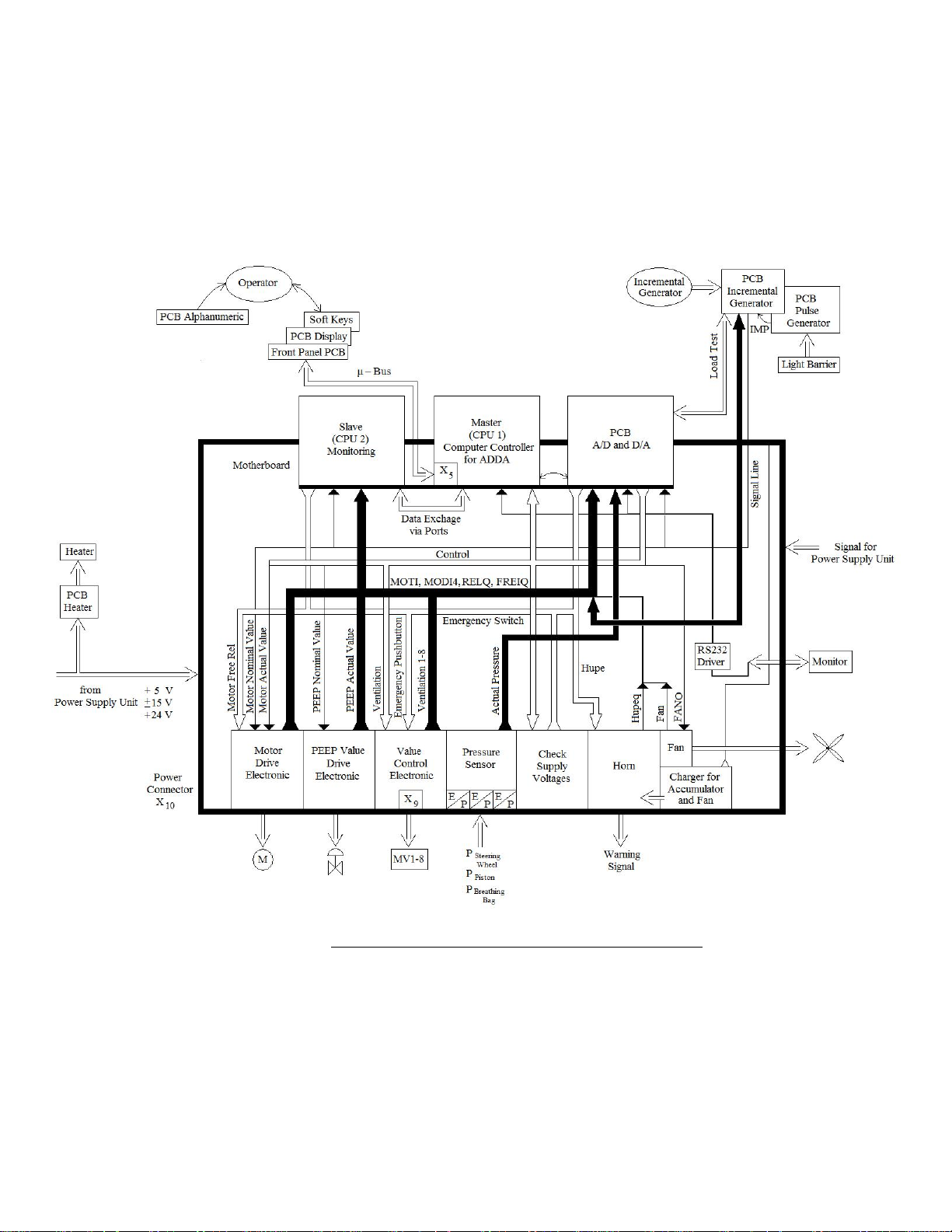
Figure 17 illustrates the block diagram of the data signal transport in the Dräger Cato
ventilator.
Figure 1 - Block Diagram of Data Transfer for Dräger Cato
II) Anesthesia Ventilator:
- The ventilator in the Cato System is an electronically controlled piston cylinder
system which is driven by an electric motor. The ventilator has a compact breathing
system which can be removed separately.
Dräger Cato Service Manual
- The operator can adjust all the parameters on the front panel of the unit via a
membrane keypad and a rotary knob (incremental encoder). The rotary knob is used
to select and confirm the selected parameters. The settings can be checked on the
display.
- The fresh gas from the fresh-gas source in the flow-meter block flows through a
tubing into the compact breathing system. The piston cylinder unit generates a
specific gas volume. This gas is supplied to the patient via the breathing system. The
pneumatic control consists of several pressure regulators and safety valves which
produce a control pressure of approximately 87 mbar. The control pressure is
supplied to the control valves in the breathing system via an electro-pneumatic
control unit (solenoid valves).
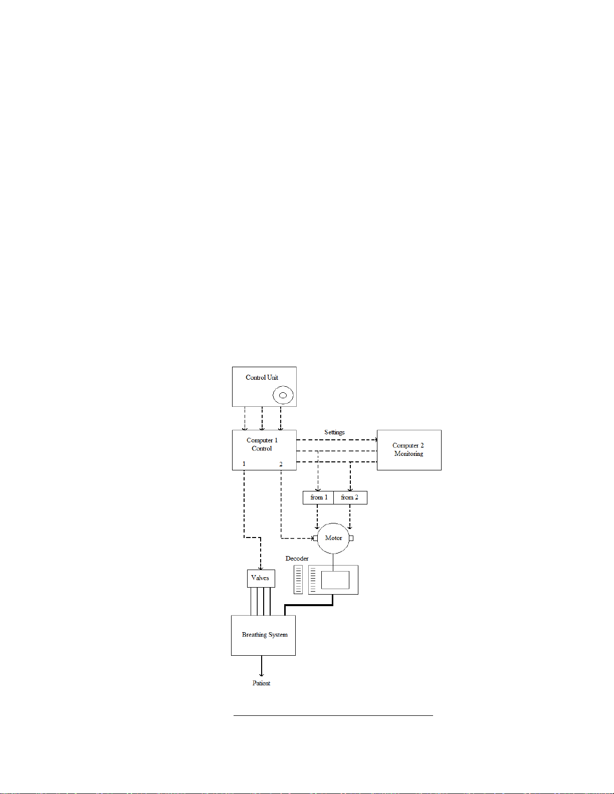
- The electronic control occurs via 2 independent, mutually monitoring
microprocessor systems. The electronics converts the valves set by the operator into
control signals for the drive motor and the control solenoid valves. The control valve
exerts a pressure (control pressure) on the pneumatic diaphragm valves in the
compact breathing system in order to generate the desired ventilation mode. The
respective position of the piston in the cylinder is determined by an incremental
encoder, and the value is channeled back to the control unit.
Figure 18 shows the ventilator control mode.
Figure 2 - Ventilator Control Mode on Dräger Cato
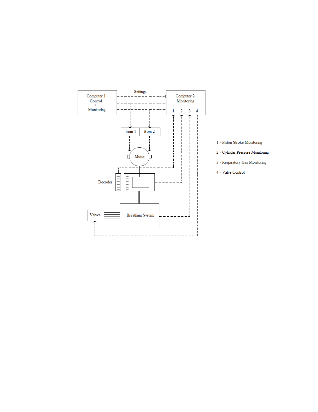
- The concept of mutual monitoring makes sure that the unit is switched off in a
defined condition should a failure occur. The following conditions are especially
monitored: piston stroke, cylinder pressure, respiratory gas pressure, and valve
control.
Figure 19 illustrates the ventilation monitoring mode.
Figure 3 - Ventilator Monitoring Mode on Dräger Cato
A) Piston Cylinder Unit:
The function of the piston cylinder unit is to deliver the fresh gas supplied from the
flow-meter block and stored in the breathing bag to the patient at a defined volume,
pressure and speed. During expiation, the piston fills with the gas expired by the
patient and with the fresh gas stored in the breathing bag. During inspiration, this
piston volume is administered to the patient by an accurate stroke. Before reaching
the patient, it flows through a CO
absorber. To ensure this gas flow, the control
2
system switches the valves of the breathing system accordingly.
The most important elements of the piston cylinder unit area piston which is moved
by a drive unit located in the rear part of the ventilator and a double roller
diaphragm which is filled with gas during operation and which functions as a
sliding bearing. The double roller diaphragm moves the piston along the inside
walls of the cylinder. The front cylinder part separates the ambient atmosphere from

the respiratory gas of the patient. Several interfaces are located on the underside
facing the ventilator. The airway pressure is measured via a pressure measurement
connection and a pressure sensor. The pressure connection provides the double
roller diaphragm with the required positive pressure of approximately 160 mbar.
The patient gas is supplied to the compact breathing system via a large lateral outlet
port.
B) Drive Unit and Fan:
The fan and the drive unit are located at the rear part of the ventilator. To access the
drive unit for repair purposes, it is necessary to remove the complete ventilator from
the Cato basic unit. Besides cooling the power electronics, the fan has to keep the
area of the control pneumatics and control electronics free from combustionsupporting gases. In the event of AIR failure O
function is monitored during the self-test and during operation. The control and the
power electronics for the fan and the drive unit is located on the Motherboard PCB
on the basic board and is connected via cable harnesses. The drive unit essentially
consists of a DC motor with a low wear rate. It is connected to an incremental
encoder and a 2-stage synchronous belt drive. This belt drive moves the two parallel
tooth belts. The catch for the piston rod of the piston cylinder unit attached to these
belts can travel very short distances (small respiratory volumes). The position of the
catch is determined both by the relative incremental encoder position and the
mechanical stop. The removal position of the piston cylinder unit is also determined
in this manner.
C) Compact Breathing System:
The compact breathing system consists of a control valve plate with the diaphragm
valves which are pneumatically triggered by the solenoid valves. The inspiratory
and the expiratory valves which are responsible for the respiratory phase and the
valve craters are located in the respiratory valve base. The APL valve for pressure
control of the airway pressure during manual ventilation is located in the respiratory
gas branch. A check valve and an emergency ventilation valve are integrated in the
airway. The flow sensor element of the PM 8050 cd is found at the connection of
respiratory hoses. The fresh gas from the flow-meter block flows into the breathing
system via the fresh gas terminal and is stored in the breathing bag. In the
inspiratory phase, it is administered to the patient through the inspiratory valve by a
piston stroke. In the expiratory phase, the gas flows through the expiratory valve
and the absorber element into the CO
makes sure the expiratory gas flows evenly through the entire surface of the soda
lime in absorber.
1
PCB: Printed Circuit Board.
can be used as drive gas. The fan
2
absorber container. The absorber element
2
1

D) Heater (Respiratory Gas):
The heater’s contact surface for indirect heating of respiratory gas is located
immediately under the built-in compact breathing system. The heater is
permanently on during operation. In case of a malfunction, a spring-loaded contact
switch causes the heater to be immediately switched off. The heater electronics are
mounted immediately under the contact surface. The maximum heating temperature
is set such that the respiratory gas temperature at the Y-piece does not exceed 30º C.
The maximum temperature of the heating plate is 65º C.
E) Electronic Control:
The following modules are monitored and/or controlled by the ventilator:
- Motor drive for the piston cylinder unit.
- Solenoid valves for the pneumatic control of the valves in the compact
breathing system.
- PEEP controller.
- Pressure sensors (airway, piston pressure, roller diaphragm pressure).
- Fan, horn, flow-meter, and background illumination.
The voltages required for electronic control are supplied from a separate power
supply unit. External data exchange with the operator is carried out via the front
panel. Data exchange with the PM8050 cd takes place via the signal line / RS232
interference.
F) Electronic Components:
- Central Electronics:
The principle printed circuit board (PCB) of the system electronics is the
Motherboard PCB. The CPU Standard 2 PCB and the CPU Monitoring PCB are
the 2 brain cells of the ventilator and use the concept of mutual data checking.
The CPU Standard 2 PCB, in conjunction with the output, input board ADDA
generates the majority of the control and actual-value signals for the peripherals
such as motor control, valve control and Front Panel PCB. Almost all the control
signals are used to produce a quit (acknowledgement) signal in the corresponding
peripheral hardware. This quit (acknowledgment) signal is then read in parallel by
the ADDA PCB and CPU Monitoring PCB using parallel ports. The analog
signals for actual values and pressures are likewise picked up by both the ADDA
PCB and the CPU Monitoring PCB. They do this independently of one another
with A/D converters.
In contrast to the ADDA PCB and the CPU Standard 2 PCB, the independent
CPU Monitoring PCB is responsible almost exclusively for the check function

described above and constantly exchanges data with the CPU Standard 2 PCB via
communication ports for the purpose of verifying the quit and analog signals. The
Motherboard PCB is located on a base plate which accommodates the solenoid
valves for the valve controller of the compact breathing system, the electronic
PEEP valve and other pneumatic elements. Also located on the Motherboard PCB
are the pressure sensors for the airway, piston and roller diaphragm pressures, the
rechargeable battery and the horn.
- Peripheral Electronics:
The remaining peripherals, including the motor, are connected to the motherboard
by the wiring harness. The Front Panel PCB is connected up to the motherboard
by a ribbon cable.
The Peripheral PCBs are:
1. Front Panel PCB with:
• Alphanumeric PCB (LED display).
• Display PCB (7-segment display, bar graph)
2. Incremental Encoder PCB (piston position).
3. Pulse Generator PCB (pulse generator at the motor).
4. Heater PCB (patient – system heating).
- Motherboard PCB:
The Motherboard PCB accommodates the 3 PCBs: ADDA, CPU Monitoring and
CPU Standard 2.
The Motherboard PCB includes the following functional units:
• Motherboard for ADDA PCB, CPU Standard 2 (CPU 1), and CPU
Monitoring (CPU 2).
• Motor controller and PEEP controller.
• Supply voltage monitor.
• Valve controller, horn, RS232, and rechargeable battery.
• Turning off the flow-meter background illumination.
• Interfaces.
- Motor Controller:
The task of the motor controller is to affect the movement of the piston in the
piston cylinder unit with the correct time and amplitude by the motor and the
gears. The control variable is the position of the piston. The target value for the
piston position is an output of the ADDA PCB as the motor target value. The
 Loading...