

Page 1
|
Fabius
°-
CE
Drager
A
medical
Dräger
and
Siemens
Company
Emergency
Care
Perioperetive
Care
Critical
Care
Inhalation
Software
Instructions
ae
Care:
Home
Anesthesia
4.n
for
Я
Use
Because
Machine
you
6816
Page 2
Contents
Contents
For
Your
Safety
and
that
of
Your
Patients
intendedÜse........................
Safety
Features
Copyright,
Typicai
Components
Fabius
Configurations
Anesthesia
Compact
SemiOpenAdapter.................................
Magill
A-Cone
Dräger-Vapor®
Vapor
Dräger-Vapor®
Selectatec®
Airway
Ventilation
User
Rotary
Displays...............
Warning
Screen
Mode
Ventilation
Function
Setting
Calibrating
Calibrating
Menu
Configuration
Language
Gas
Preparation
Caution
Gas
Cylinders
Cylinders
Electrical
Eguipotential
Attaching
Preparing
Fitting
Breathing
Fitting
Fitting
Fiting
Inserting
Fitting
Fabius
Inhalation
Breathing
Switch
Interlock
Monitor
interface
Control し に に に
Tones
Display
Selection
Alarm
Display
Compensation
During
supply
the
the
the
the
the
the
..
Trademark,
.............,.....,.,,..,....,4...,..
Ventilator
Breathing
.,.....,...,,...,......,....,4........
and
.....,,..,,....,,,....,...,,.
Parameter
Buttons
Limits
the
The
Button
Menu
Selection
............
...........
with
Threaded
with
Pin-index
Supply
Bonding
Manual
the
Ventilator
CO2
System
Inspiratory
Expiratory
Pressuredimiting
Flow
Waste
and
Disclaimer
Configurations
Anesthesia
......
....
System
Cireuit
.....,..,,,...,....,,,....,..,,,....,
Anesthetic
System
.........,....,........,,.....
......................,..
Machine
.........,,...,.....,.....
............,,...,,..,.......
Agent
Vaporizer
ーー
with
Control
Monitor
.......,...,.,......,.........,....,
Configuration
Buttons
Units
Operating
に に に に し に に
トト に レト
1.100
.......
Buttons
.....,.........,.....
Concept
レト
eee
Oxygen
Sensor
Flow
Sensor
.....
...
Menu
Setting
Transport
.
.......,...,,....,,...,
...
...........,........,......
Menu
....,........,......,
Connectors
Mounting
...........,......,,...,....,,,...,
..........
Ventilation
Absorber
Gas
on
..................,,..............
Valve
Valve
Sensor
............,...............
Outlet
....,.......,,,.....
Bag
.
the
Compact
.......
Valve
.
Port
.............,,,..,..
..............
er
Notices
トッ レト ト レート
............
.
.
トト
トー
ρ
レー て て
νοκ
..5
..
.
.
..
…
ων
..
..
..
Connecting
4
Fitting
Connecting
5
Connecting
Connecting
5
Connecting
Connect
6
ConnectingiheO2Sensor...........................
Installing
10
CompactBreathingSystem..........................
Anesthetic
10
Scavenger
10
Semi-open
10
A-Cone
10
Installation
11
Removing
11
InstallingtiheCO2>Absorber..........................
12
Additional
12
Operation
Nitrogen
13
Adjusting
SettingtiheVapor......................
Ventilation
Semi-open
Spontaneous
Manual
Automatic
Pressure
Using
A-Cone
OzFlush
ReplacingCO2Absorbent...........................
Replacing
Shut-down
Switch
(Dráger-Vapor“)
ClosetheMeteringValves
Switch
Disconnect
De-pressurizing
Switch
Remove
Fault - Cause — Remedy
Dismantling
Dismaniling
for
26
26
27
27
Cleaning
Dismantling
DismantlingtheExpiratoyValve
Dismantling
Dismantling
Dismantiing
the
Compact
Microbial
Switch 上 に に に に に
Ventilation
the
Lever
Off
off
Off
the
Filters
the
Breathing
the
02
the
Pressure
the
Flow
the
Magill
Anesthetic
Gas
Scavenging
System
Compact
of
the
Semi-OpenAdapter
the
Semi-Open
Equipment
......................
Wash-out
the
Fresh
Modes
Compact
Breathing
Ventilation
limited
ventilation
Magill
Breathing
Selection
..............
Used
Absorbent
.......,.....,.....,....,,....,....,.,..
the
Anesthetic
ручке
anesthesia
the
Fresh-gas
the
the
Control
O2
Sensor......,.,....,,...,,,...,,....
Down
the
Compact
に に レー レレ に トー
the
Inspiratory
the
Flow
the
Pressure-imiting
the
Absorbent
Breathing
..............
Hoses
Sensor
Capsule
Sensor
Sensor
inhalation
Gas
Scavenging
System
Connections
Breathing
に に に に に に
Adaptor
..........,...,,,.........,....
(when
Required)
Gas
Composition
with
the
Compact
Breathing
...........,....,.....,.,...,
..................................
...,.............,...,,...,,....
System
..........
System
..
...................
.....................
......
Device
AGS
for
the
System
レレ
レー
and
2.
System
.........,...........,....
. .
............
ーー
.
Hose
to
..............
................
ドッ
トド
.................
elele
..................
.................
6.0
and
................
(Compact
Agent
...........................
ventilator
Supply
Anesthesia
Unit
..........................,
...........,......,....,......,..
Breathing
トト
Valve
Sensor
..............,,....,....
Canister
System)
Vaporizer
.......................
.....................
Machine
.
System
トト トト
レッ
トット
.
......................
Valve
...................
the
トー
ee
..........
ттт
ーー ス いい
ュー
レト
ここ
...
..
.
...
ーー
...
・
-
27
28
28
29
29
30
31
32
32
33
33
33
34
35
36
37
37
37
37
38
38
39
40
41
42
43
43
44
44
45
47
49
ΠΠ:
Page 3
Conients
Minimum
Magil!
Dismantling
Disinfecting/Cleaning
Wipe
Flow
of
Anesthesia
Breathing
Device
Parts
of
Disinfecting
.........................
........
the
Ventilator
..............................
............,.,,,....
DisinfectingandCleaning...........................
Automatic
Sterilzind
Checking
Maintenance
Disposal
What'swhat
Compact
Compact
TechnicalData....................................
DiagramS
Compact
Semi-Open
Gas
Cleaning/Disinfecting
エレ
に に に に に に トト
Readiness
intervals
.,,..,...,..,.,,,.......,,,,.,..,.,,,,,,.,
for
..............................
................
Breathing
Breathing
Breathing
Compact
Delivery
Unit
System,
System,
System
Breathing
(3-Gas
version)
Machine
に に に トー
トト
Operation
0
Front
Back
........
System
トレ
レレ
レト ト トト
...................
eee
...
.....,,.,.......,...,
. .
.....................
..............
レット
レト て トト
こてこて
eneree
・
.
50
50
51
51
52
52
52
53
53
56
62
62
63
64
Âbbreviations
Used
..................,,.,.,,,.,,....
DailyPre-UseCheckforFabius
Index
sise.
......................
65
66
71
Page 4
For
Your
Safety
For
Your
Patients
and
that
Safety
of
Your
and
Patients
that
of
Your
Strictly
Any
observation
The
Maintenance
The
service
We
Only
Observe
Accessories
Do
(86
and/or
be
iramediately
cracks,
foliow
use
of
the
of
apparatus
Observe
equipment
Repair
carried
DrägerService
maintenance.
Even
result
parts
may corrode
the
used}
apparatus
personnel
and
general
out by
recommend
authentic
chapter
not
use
accessory
06
304,
revision
reusable
sterilized)
increased
of
various
(e.g.
disinfectant
if
deformation,
and
the
the
Instructions
apparatus
these
is
only
Instructions
must
trained
that a service
and
Drager
accessories
factors
material).
external
requires
instructions.
to
be
for
be
inspected
at
six
month
overhaul
service
that
all
repairs
spare
"Maintenance
parts
index
00).
have a limited
the
service
when
residues
Such
signs
discoloration,
for
Use
full
used
for
Use
of
and
intervals.
of
the
apparatus
personnel.
contract
also
parts
may
Intervals".
other
than
(e.g.
parts
useful
life
reduced
handling
left
behind
parts
of
wear
peeling,
understanding
purposes
the
which
must
become
specified
supplementary
serviced
be
be
be
those
life,
and
by
may
obtained
carried
out
used
for
in
the
can
be
Wear
and
considerably
conditioning such
after
autoclaving
be
replaced
evident,
etc.
and
strict
here.
trained
only
be
with
by
them.
order
list
cleaned
tear
as
such
Liability
The
irrevocably
that
employed
used
Drager
non-compliance
The
delivery
recommendations
Dräger
may
a
as
for
proper
liability
for
transferred
the
apparatus
or
authorized
in a manner
cannot
warranty
and
of
Drager
Medical
function
the
proper
is
serviced
not
conforming
be
held
with
the
liability
are
likewise
given
AG & Co.
or
damage
function
to
the
by
DragerService
responsible
recommendations
provisions
above,
KG
owner
or
repaired
to
not
of
the
or
its
for
of
modified
apparatus
operator
by
personnel
or
if
the
intended
damage
given
the
terms
by
is
to
the
apparatus
use
caused
above.
of
sale
the
extent
noi
is
by
and
Not
for
Use
in
This
apparatus
areas
where
combustible
occur,
Safe
connection
Electrical
these
consultations
connections
Instructions
with
Areas
is
neither
with
for
the
of
Explosion
approved
or
explosive
other
electrical
to
equipment
Use
should
respective
Hazard
nor
certified
gas
mixtures
equipment
which
is
not
only
be
made
manufacturers
for
use
in
are
likely
listed
in
following
or
an
expert.
to
Page 5
intended
Use
Intended
Fabius
is
continuous
of
at
Jeast 5 kg.
Fabius
is
Use
an
inhalation
fresh
intended
gas
for
rooms.
It
may
be
used
with
O2,
gas
pipeline
Fabius
providing
The
following
©
Automatic
©
Pressure
@
Manual
©
Spontaneous
The
Fabius
electronically
pressure
centration
According
Modules - Particular
the
volume
additionally
with
the
As
per
Special
concentrations
EN
740
available
Fresh
anesthetic
Do
not
ether,
system
or
can
be
equipped
fresh gas
decoupling,
ventilation
Ventilation
limited
ventilation
Ventilation
Breathing
can
be
equipped
controlled
(Paw),
the
volume
(FiO2).
to
EN
740
(V)
and
the
monitored
ventilator.
EN
740
(Anesthetic
Reguirements),
of
COz
reguires
for
gas
that a manual
emergenoy
enrichment
vaporizer.
use
readily
flammable
cyclopropane,
Requirements)
anesthesia
flow
for
patients
use
in
operating,
N20,
and
AIR
by
externally
with a compact
PEEP,
options
are
((PPV),
(IPPV/PLV),
(MAN),
(SPONT).
with
an
ventilator,
(V)
which
and
(Anaesthesia
oxygen
concentration
in
the
case
of a Fabius
Workstations
additional
and
monitoring
anesthetic
ventilation
use,
is
provided
etc.
by
anesthetic
machine
with
with a body
induction
supplied
mounted
by a medical
gas
breathing
and
pressure
available:
electrically
the
inspiratory
operated
monitors
Workstations
the
airway
pressure
(FiO2)
not
and
their
of
the
agent
is
reguired.
bag
must
the
Dráger-Vapor“
agents
weight
and
recovery
cylinders.
system,
limitation.
and
the
airway
oxygen
con-
and
Their
(Paw),
must
be
eguipped
Modules
be
such
as
Safety
@
Monitoring
©
Automatic
©
integrated
{control
21
Burns
ventilation
electrical
breathing
Caution: Do
tomography
endangering
Caution:
10
meters
malfunctions
endangering
Copyright,
Copyright
Copyright
of
this
transcribed,
means,
recording,
—
Registered
1 1 1
DrägerService®
Fabius?
Dráger
Drágersorb?
are
—
Selectatec?
is a registered
Features
O2
S-ORC = Sensitive
device
vol.%).
may
occur
tubes
surgery
tubes
not
equipment.
the
Do
not
from
in
the
Trademark,
by
Drager
publication
or
stored
electronic
without
trade
Vapor“
registered
trade
trade
of P,
V,
FiO2
shortage
to
ensure
if
antistatic
are
used
equipment.
are not
recommended.
use
Fabius
Malfunctions
patient.
use
mobile
the
machine.
electrical
medical
patient.
Medical,
may
be
in a retrieval
or
mechanical,
written
marks
800
Plus
marks
mark
alarm
and
Oxygen
minimum
or
electrically
in
combination
Therefore,
in
the
environment
phones
within a distance
Mobile
phones
equipment,
and
Disclaimer
Inc.
All
reproduced,
system
including
permission
of
Drager
of
Datex-Ohmeda.
N2O
cut-off
Ratio
O2
concentration
conductive
with
high-frequency
these
types
of
may
result,
can
thereby
rights
reserved,
transmitted,
in
any
photocopying
of
Drager
Medical
AG & Co.
Controller
of
of
NVR
thereby
of
cause
Notices
No
part
form
or
by
and
Medical,
inc.
KG.
any
Page 6
Typical
Fabius
Configurations
Typical
General
The
Fabius
consisting
components
requirements
Versions
2-gas
3-gas
Optionally
two
cylinder
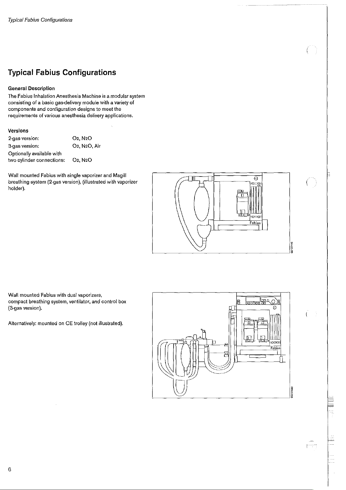
Wall
breathing
holder).
Fabius
Description
Inhalation
of a basic
and
version:
version:
available
connections:
mounted
system
Anesthesia
gas-delivery
configuration
of
various
with
Fabius
with
(2-gas
Configurations
Machine
module
designs
anesthesia
02,
N20
O2,
N20,
O2,
N20
single
vaporizer
version),
(illustrated
is a modular
with a variety
to
meet
delivery
applications.
Air
and
with
system
of
the
Magill
vaporizer
Wall
mounted
compact
(3-gas
version).
Alternatively:
Fabius
breathing
mounted
with
system,
on
dual
vaporizers,
ventilator,
CE
trolley (not
and
control
illustrated).
box
00137440
00237440
Page 7
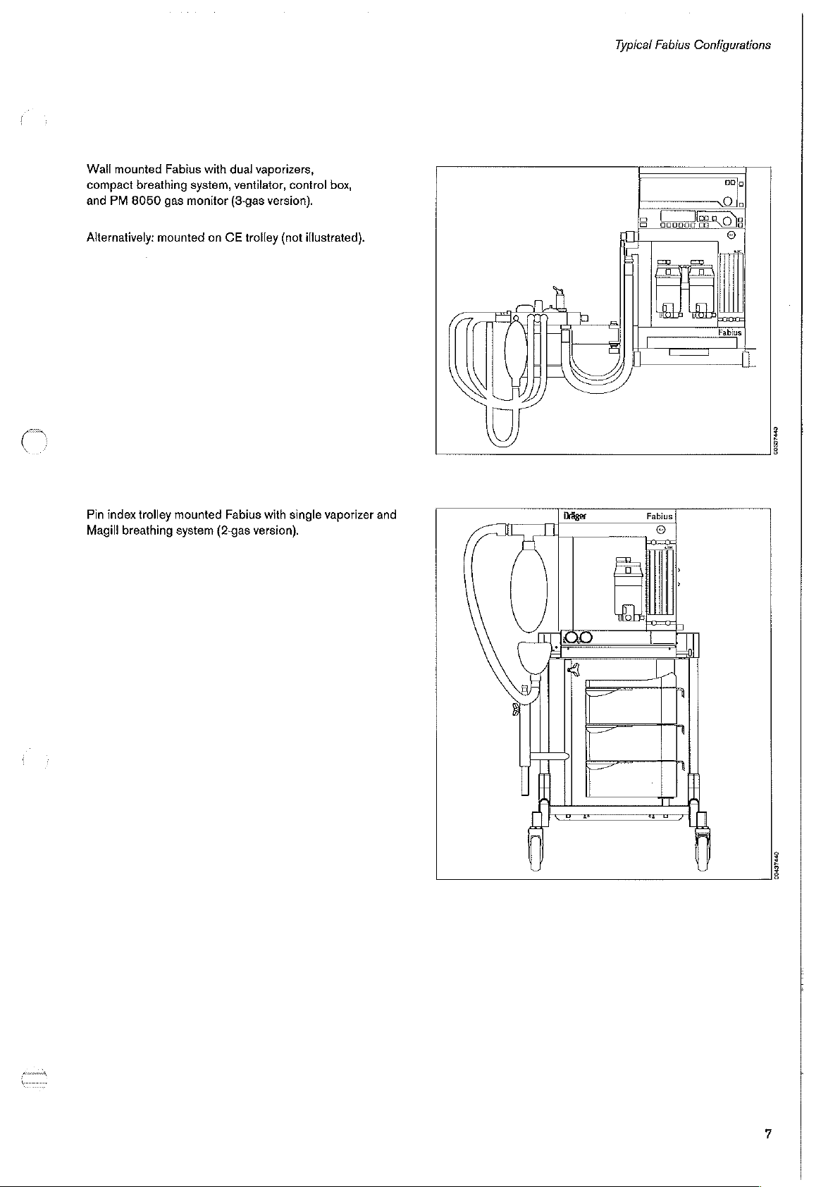
Wall
mounted
compact
and
PM
Fabius
breathing
8050
gas
with dual
system,
monitor
vaporizers,
ventilator,
(3-gas
version).
control
box,
Typical
Fabius
Configurations
CON
Alternatively:
5
Pin
index
Magill
mounted
trolley
breathing
on
mounted
system
CE
trolley (not
Fabius
(2-gas
with
single
version).
illustrated).
vaporizer
and
00337440
Fabius
00437440
Page 8
Typical
Fabius
Configurations
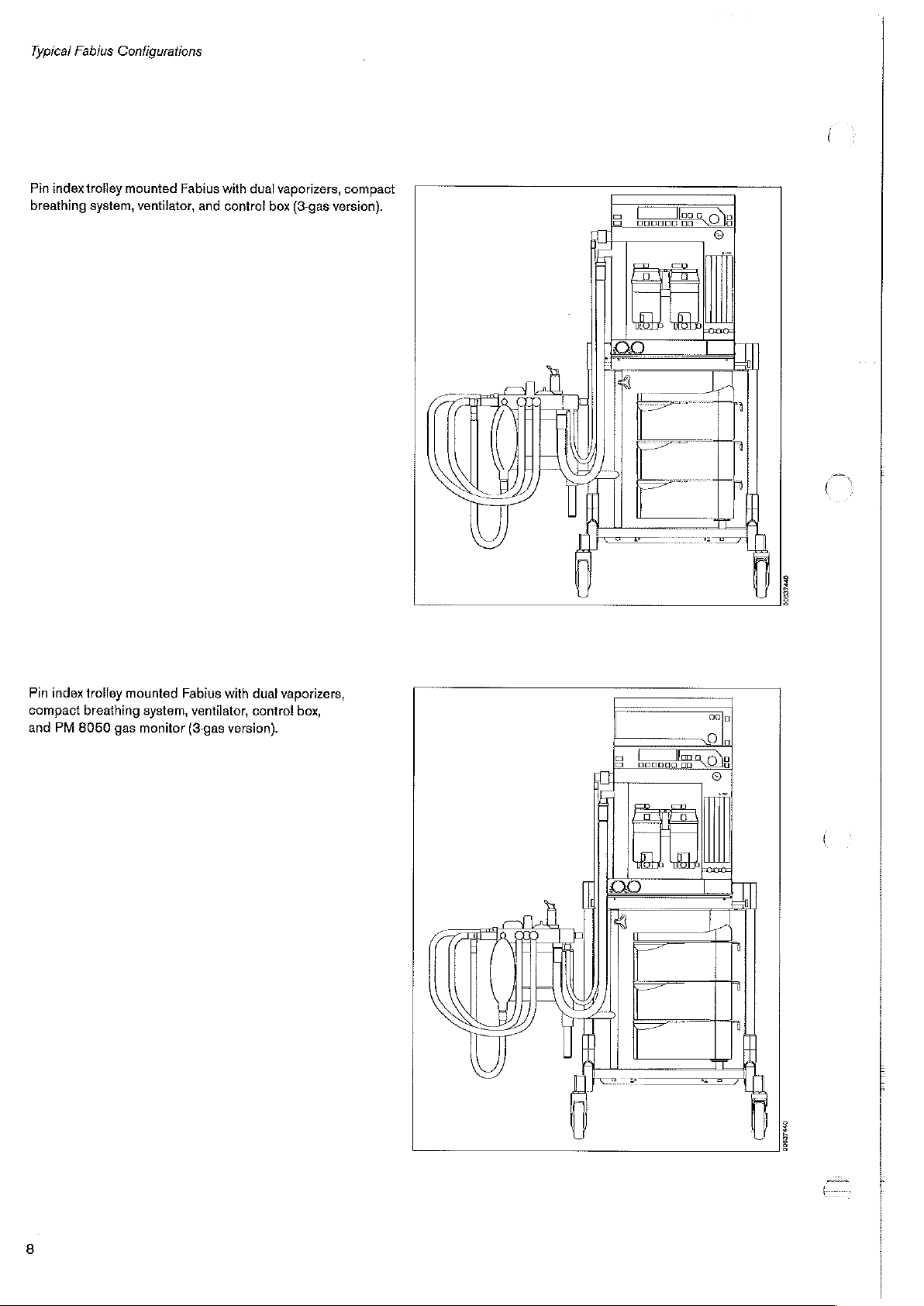
Pin
index
trolley
breathing
mounted
system,
Fabius
ventilator,
and
with
dual
vaporizers,
control box
(3-gas
compact
version).
a
а
©
00637440
Pin
index
compact
and
PM
trolley
mounted
breathing
8050
gas
Fabius
system,
monitor
with
dual
ventilator,
(8-gas
control
version).
vaporizers,
box,
00627440
Page 9
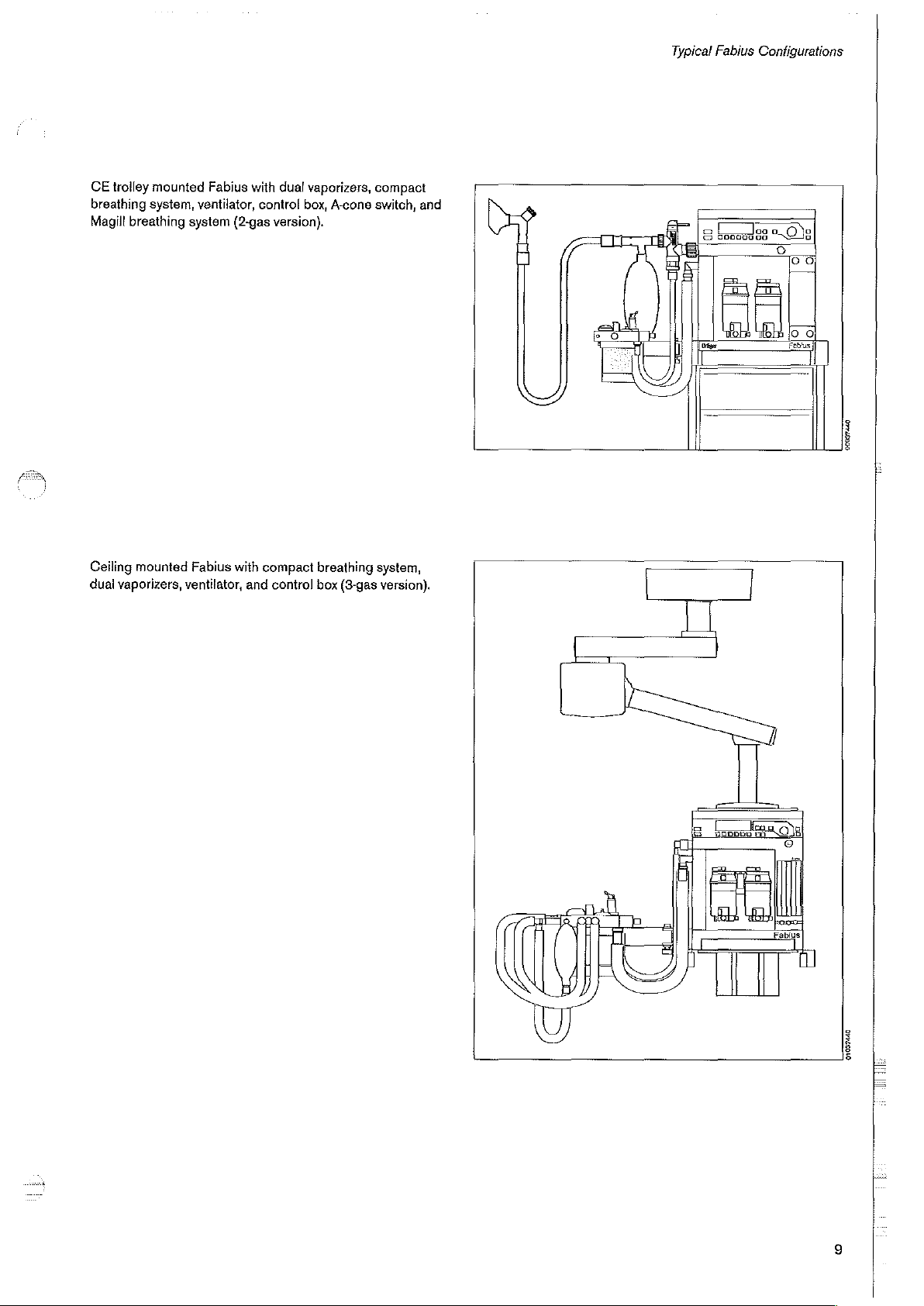
Typical
Fabius
Configurations
CE
trolley
breathing
Magill
breathing
Ceiling
mounted
dual
vaporizers,
mounted
system,
system
ventilator,
Fabius
ventilator,
(2-gas
Fabius
with
and
with
dual
control
version).
compact
control box
vaporizers,
box,
A-cone
breathing
(3-gas
compact
switch,
and
system,
version).
8
booed
88
0%
00037440
01037440
Page 10
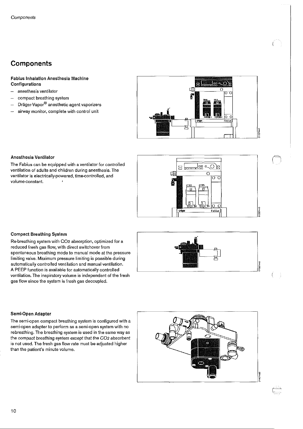
Components
Components
Fabius
Inhalation
Configurations
—
anesthesia
—
compact
一
DrágerVapor?
ー
airway
Anesthesia
The
Fabius
ventilation
ventilator
volume-constant.
ventilator
breathing
monitor,
Ventilator
can
of
adults
is
electrically-powered,
Anesthesia
system
anesthetic
complete
be
equipped
and
Machine
agent
vaporizers
with
control
with a ventilator
children
during
time-controlled,
s
unit
for
controlled
anesthesia.
The
and
Eroi
=
[=
(ee
Ha
ER
圖
m | Че.
—
5
бо
abius
био
01237440
Compact
Re-breathing
reduced
spontaneous
limiting
automatically
A
PEEP
ventilation.
gas
Semi-Open
The
semi-open
rebreathing.
the
is
than
fresh
valve.
function
flow
since
semi-open
compact
not
used.
the
patient’s
Breathing
system
breathing
controlled
The
Adapter
adapter
The
breathing
The
System
with
gas
flow,
with
mode
Maximum
inspiratory
the
compact
pressure
ventilation
is
available
system
to
perform
breathing
system
fresh
gas
minute
CO2
absorption,
direct
to
manual
limiting
for
automatically
volume
is
fresh
gas
breathing
as a semi-open
system
except
flow
rate
volume.
optimized
switchover
mode
is
possible
and
manual
is
independent
decoupled.
system
is
is
used
in
that
the
must
be
adjusted
for
from
at
the
pressure
during
ventilation.
controlled
of
the
configured
system
with
the
same
way
CO2
absorbent
higher
a
fresh
with
no
as
a
01997440
A
01437440
10
Page 11
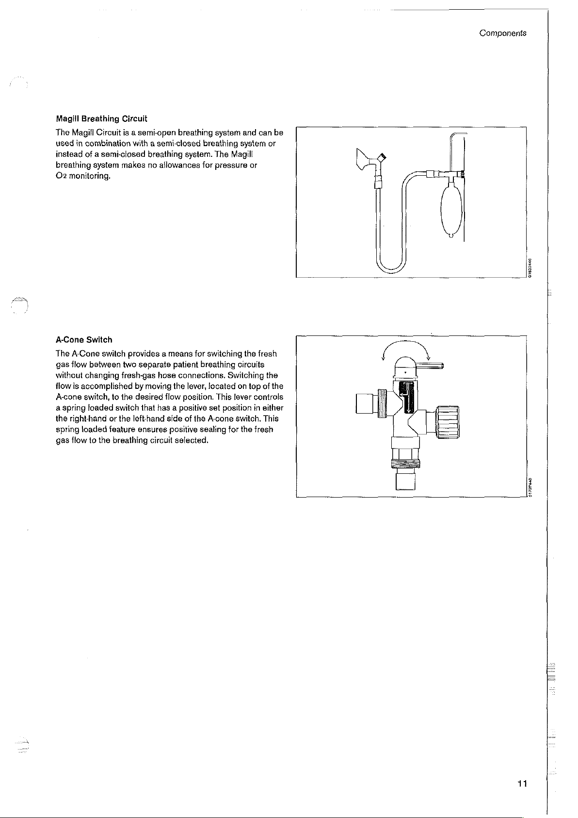
Magill
Breathing
The
Magill
used
in
combination
instead
of a semi-closed
breathing
02
monitoring.
Circuit
system
Circuit
is a semi-open
with a semi-closed
breathing
makes
no
breathing
allowances
breathing
system.
for
system
and
system
The
Magill
pressure
or
can
Components
be
or
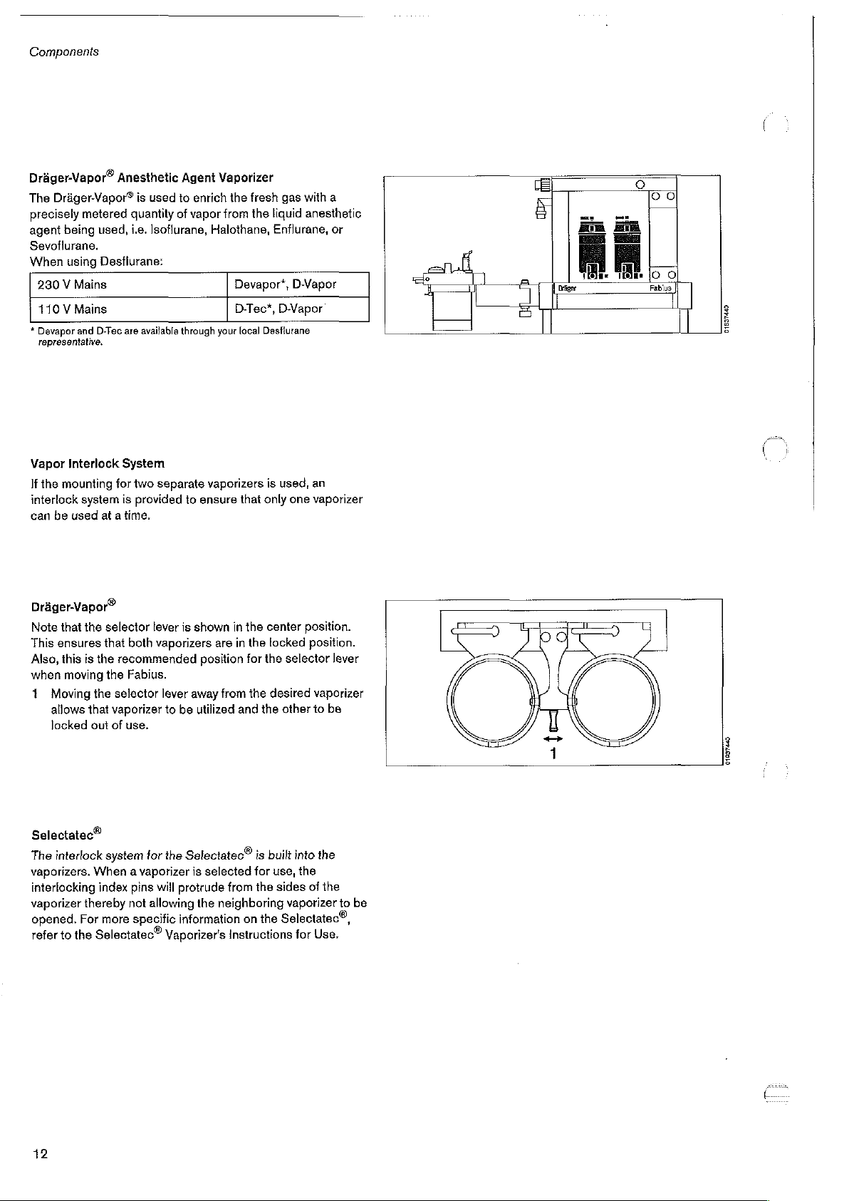
A-Cone
The
A-Cone
gas
flow
without
flow
is
accomplished
A-cone
a
spring
the
right-hand
spring
loaded
gas
flow
Switch
switch
between
changing
switch,
to
loaded
or
feature
to
the
breathing
provides a means
two
separate
fresh-gas
the
switch
the
hose
by
moving
desired
that
has a positive
lefthand
ensures
circuit
for
patient
breathing
connections.
the
lever,
flow
position.
side
of
the
positive
sealing
selected.
switching
circuits
Switching
located
A-cone
This
set
position
on
lever
switch,
for
the
the
fresh
top
of
controls
in
either
This
fresh
the
the
01637440
01787440
11
Page 12
Components
Drdger-Vapor®
The
Dr&ger-Vapor®
precisely
agent
Sevoflurane.
When
230V
110 V Mains
*
Devapor
representative.
Vapor
If
interlock
can
being
the
mounting
be
metered
using
Mains
and
Interlock
system
used
Anesthetic
is
used
quantity
used,
i.e.
Isotiurane,
Desflurane:
D-Tec
are
available
System
for
two
separate
is
provided
at a time.
Agent
to
enrich
of
vapor
through
to
ensure
Vaporizer
the
fresh
gas
with
a
from
the
liquid
anesthetic
Halothane,
your
vaporizers
Enflurane,
Devapor*,
D-Tec*,
local
that
DVapor
D-Vapor
Desflurane
is
used,
only
one
or
an
vaporizer
E
δ
E
=
Fem
ES
n)
ome
A
Es
圖
ο
So
rable
|
g
Е
Dräger-Vapor®
Note
that
the
This
ensures
Also,
this
is
when
moving
1
Moving
allows
that
locked
out
Selectatec®
The
interlock
vaporizers.
interlocking
vaporizer
opened.
refer
to
the
thereby
For
selector
that
the
the
the
system
When a vaporizer
index
more
Selectatec®
lever
both
vaporizers
recommended
Fabius.
selector
vaporizer
of
lever
use.
for
pins
will
not
allowing
specific
to
the
Vaporizer's
is
away
be
Selectatec®
is
protrude
information
shown
in
are
in
position
from
utilized
selected
from
the
neighboring
Instructions
the
center
the
locked
for
the
the
desired
and
the
is
built
for
use,
the
on
the
Selectatec®,
position.
position.
selector
vaporizer
other
to
into
the
the
sides
of
vaporizer
for
Use.
lever
be
the
to
be
TT
pa
-a
II
01807620
42
Page 13
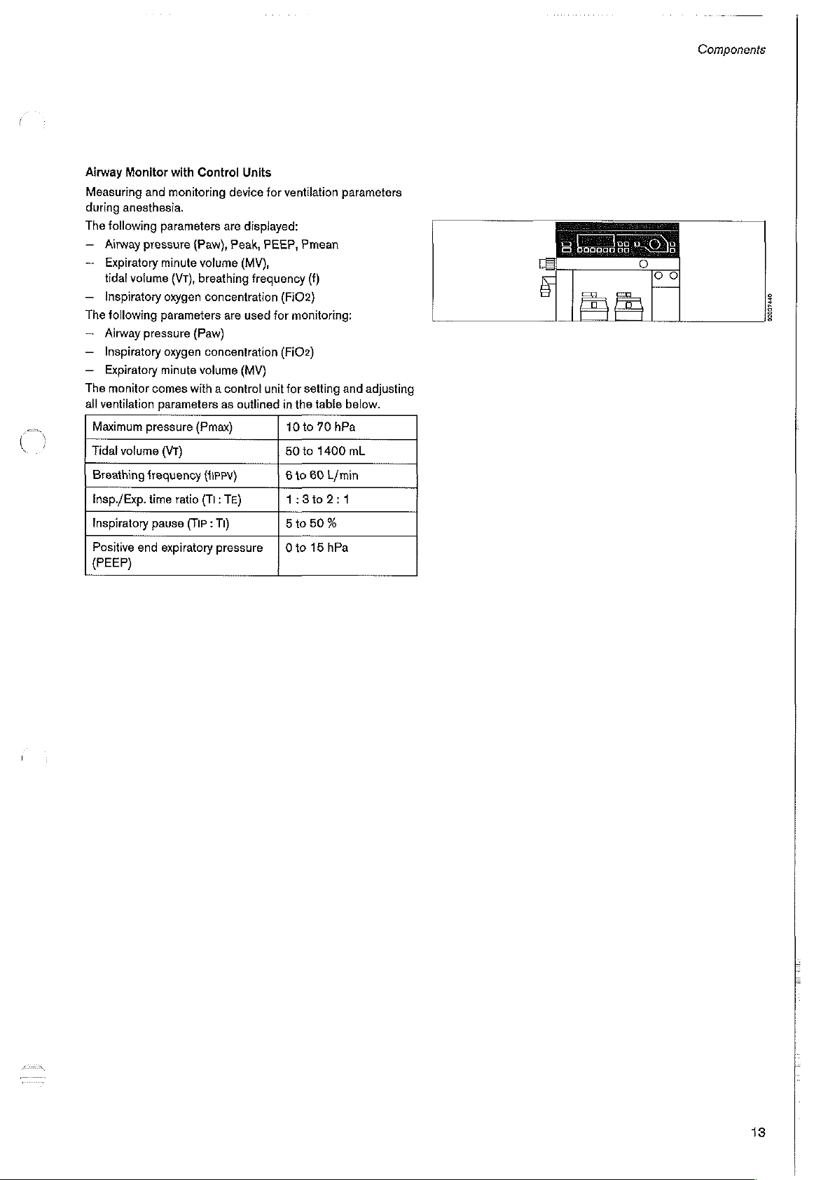
Airway
Monitor
Measuring
during
anesthesia.
The
following
—
Airway
—
Expiratory
tidal
volume
ー
Inspiratory
The
following
~
Airway
—_
Inspiratory
—
Expiratory
The
monitor
all
ventilation
Maximum
Tidal
volume
Breathing
Insp./Exp.
Inspiratory
Positive
(PEEP)
end
with
and
monitoring
parameters
pressure
minute
(V1),
oxygen
parameters
pressure
oxygen
minute
comes
with a control
parameters
pressure
(VT)
frequency
time
ratio
pause
(TIP : Tl)
expiratory
Control
(Paw),
volume
breathing
(Paw)
volume
(Pmax)
Units
device
are
displayed:
Peak,
(MV),
frequency
concentration
are
used
concentration
(MV)
as
outlined
{ИРРУ\)
(T1:
TE)
pressure | Oto
for
ventilation
PEEP,
Pmean
(FiO2)
for
monitoring:
(FiO2)
unit
for
setting
in
the
10
to
50
to
8
to
1:3t02:1
5
to
(f)
table
70
1400
60
L/min
50
%
15
hPa
parameters
and
adjusting
below.
hPa
mL
Componenis
02037840
13
TNT
Page 14
Ventilation
and
Monitor
Ventilation
Concept
User
Interface
Both
the
monitor
by
way
of
—
buttons
—
rotary
—
displays,
—
warning
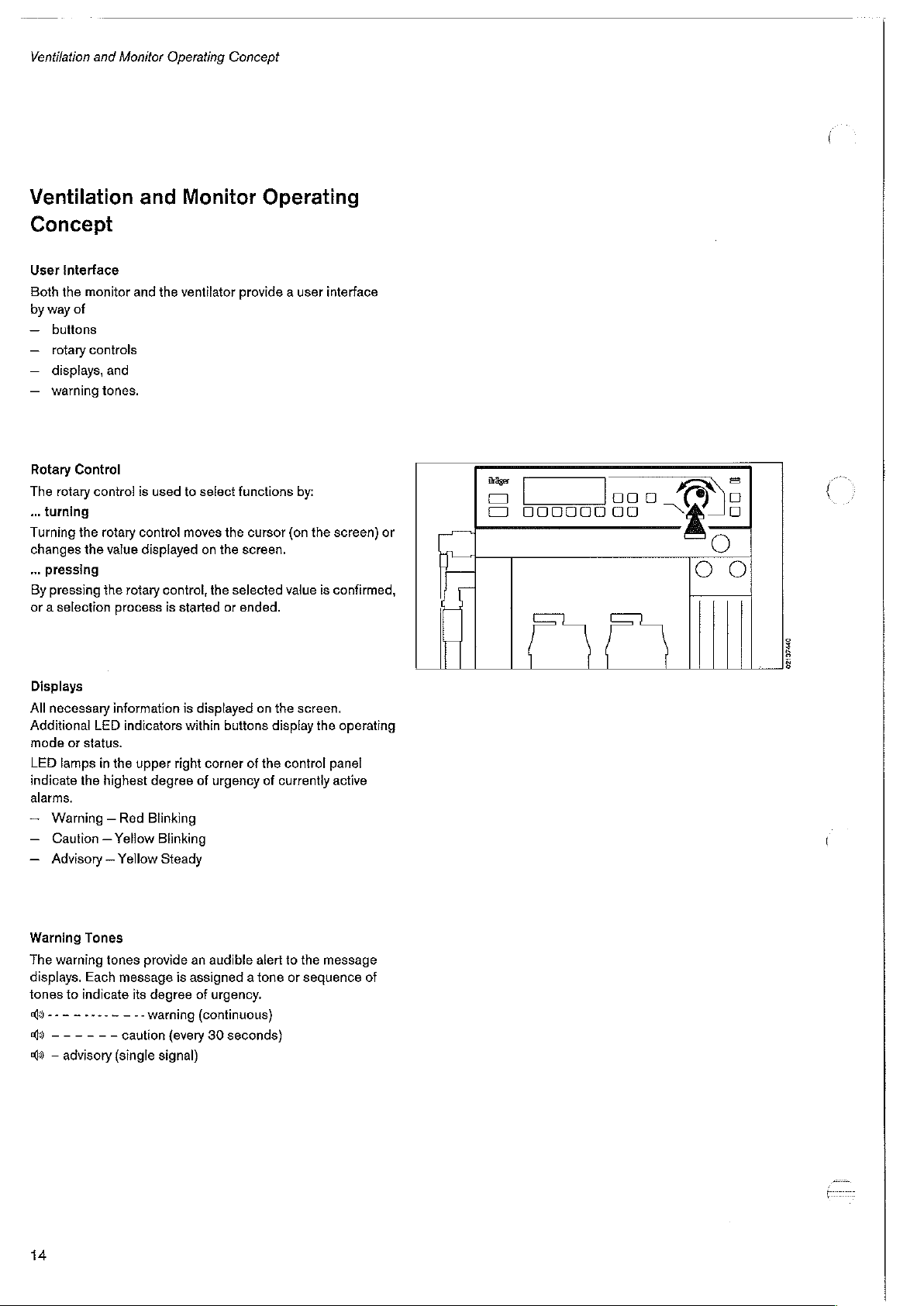
Rotary Control
The
rotary
«
turning
Turning
changes
…
By
or a selection
the
the
pressing
pressing
and
controls
and
tones.
conirol
rotary
value
the
rotary
process
Operating
and
Monitor
the
ventilator
is
used
to
control
moves
displayed
control,
is
started
Concept
Operating
provide a user interface
select
the
on the
the
selected
or
functions
cursor
screen.
ended.
by:
(on
value
the
screen)
is
confirmed,
or
Sager
に
コ
O
000000
900
ロロ
II
O
ο
ο
Displays
All
necessary
Additional
mode
LED
indicate
alarms.
—
—
—
Warning
The
displays.
tones
a)
)
$ — advisory
LED
or
status.
lamps
in
the
highest
Warning — Red
Caution — Yellow
Advisory — Yellow
Tones
warning
-- - ~----~
------
Each
to
indicate
tones
information
indicators
the
upper
message
its
—--
warning
caution
(single signal}
is
within
right
degree
Blinking
Blinking
Steady
provide
is
assigned a tone
degree
{every
displayed
of
an
of
(continuous}
buttons
corner
of
urgency
audible
urgency.
30
seconds)
on
the
display
the
control
of
currentiy
alert
to
or
screen.
the
operating
panel
active
the
message
sequence
of
Il
02137440
14
Page 15
Ventilation
and
Monitor
Operating
Concept
Screen
1
2
3
4
Mode
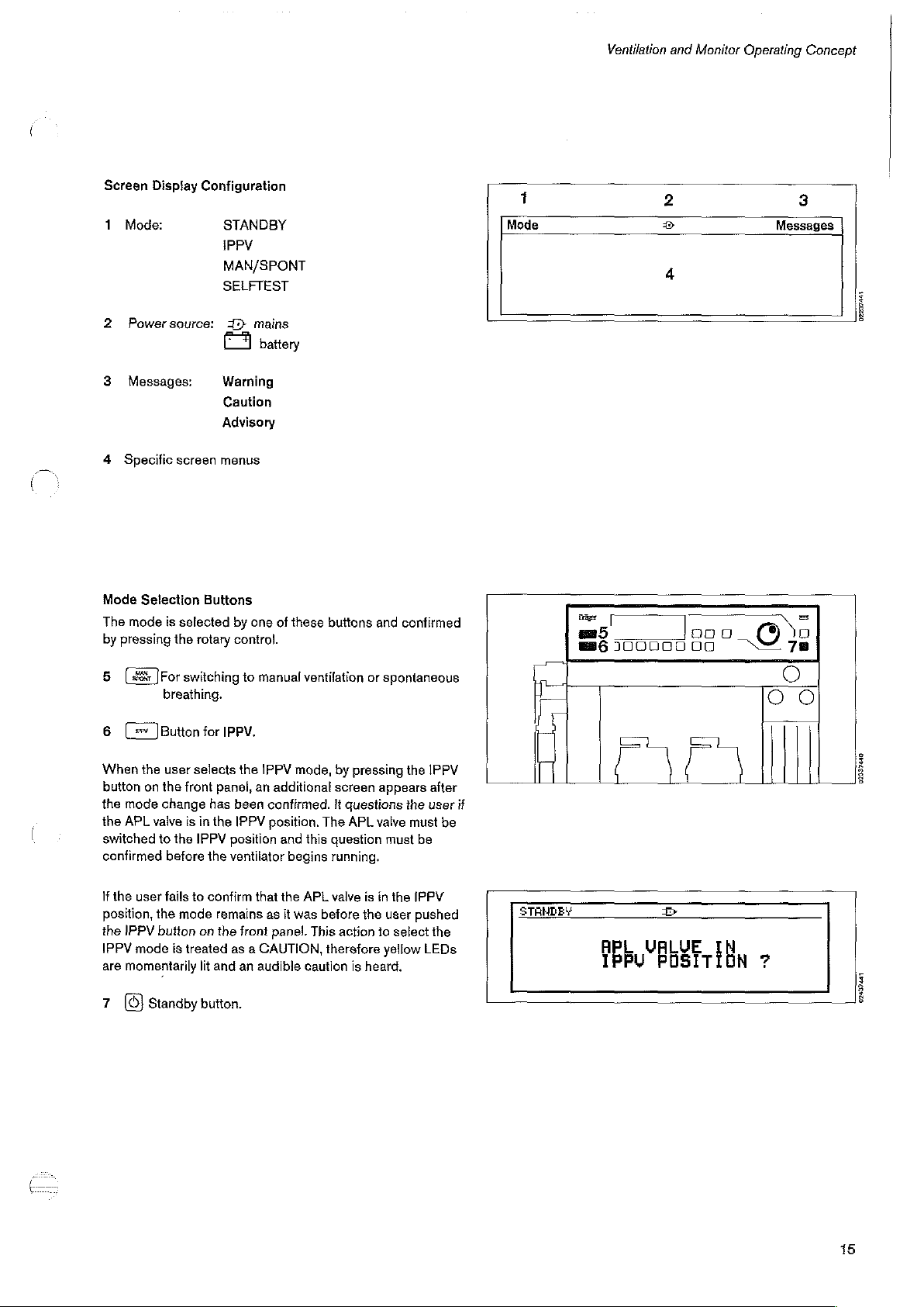
The
by
5
6
Display
Mode:
Powersource:
Messages:
Specific
Selection
mode
pressing
[48%
]For
(=
]Button
Configuration
STANDBY
IPPV
MAN/SPONT
SELFTEST
1)
Warning
Caution
Advisory
screen
menus
Buttons
is
selected
the
rotary
switching
breathing.
for
IPPV.
mains
battery
by
one
of
control.
to
manual
these
buttons
ventilation
and
confirmed
or
spontaneous
Mode
1
Dee
æ5
86
100000
2
4
000
00
©
Messages
E
3
|
0223744
|
When
the
user
button
on
the
the
mode
change
the
APL
valve
switched
confirmed
If
position,
the
IPPV
are
7
to
the
user
fails
the
IPPV
button
mode
momentarily
Standby
selects
front
is
in
the
IPPV
before
to
mode
on
is
treated
lit
button.
the
panel,
an
has
been
the
IPPV
position
the
ventilator
confirm
that
remains
the
front
as a CAUTION,
and
an
audible
IPPV
mode,
additional
confirmed.
position.
as
panel.
and
this
begins
the
APL
it
was
caution
The
before
This
by
pressing
screen
appears
it
questions
APL
valve
question must
running.
valve
is
in
the
the
user
action
to
select
therefore
is
heard.
yellow
the
IPPV
after
the
user
must
be
IPPV
pushed
the
LEDs
be
if
STAHDEY
IPBU
CI)
tr
POSTTĚDN
>
02337440
02439441
15
Page 16
Ventilation
and
Monitor
Operating
Concept
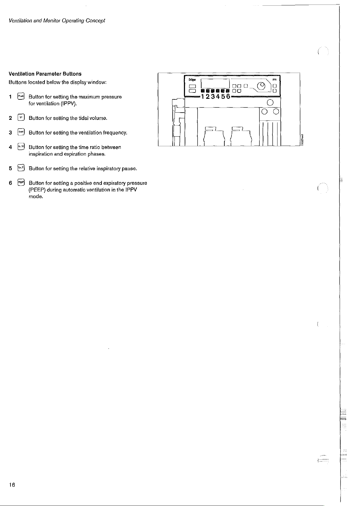
Ventilation
Buttons
1
5
6
located
Button
for
Button
Button
Button
inspiration
Button
Button
(PEEP)
mode.
Parameter
ventilation
Buttons
below
the
for
setting
(IPPV).
for
setting
for
setting
for
setting
and
for
setting
for
setting a positive
during
automatic
display
window:
the
maximum
the
tidal
the
ventilation
the
time
expiration
the
relative
phases.
ventilation
pressure
volume.
freguency.
ratio
between
inspiratory
end
expiratory
in
pause.
the
IPPV
pressure
πα
|
=
|
Doo
ロロ
1
>
=
Q
개
(
16
Page 17
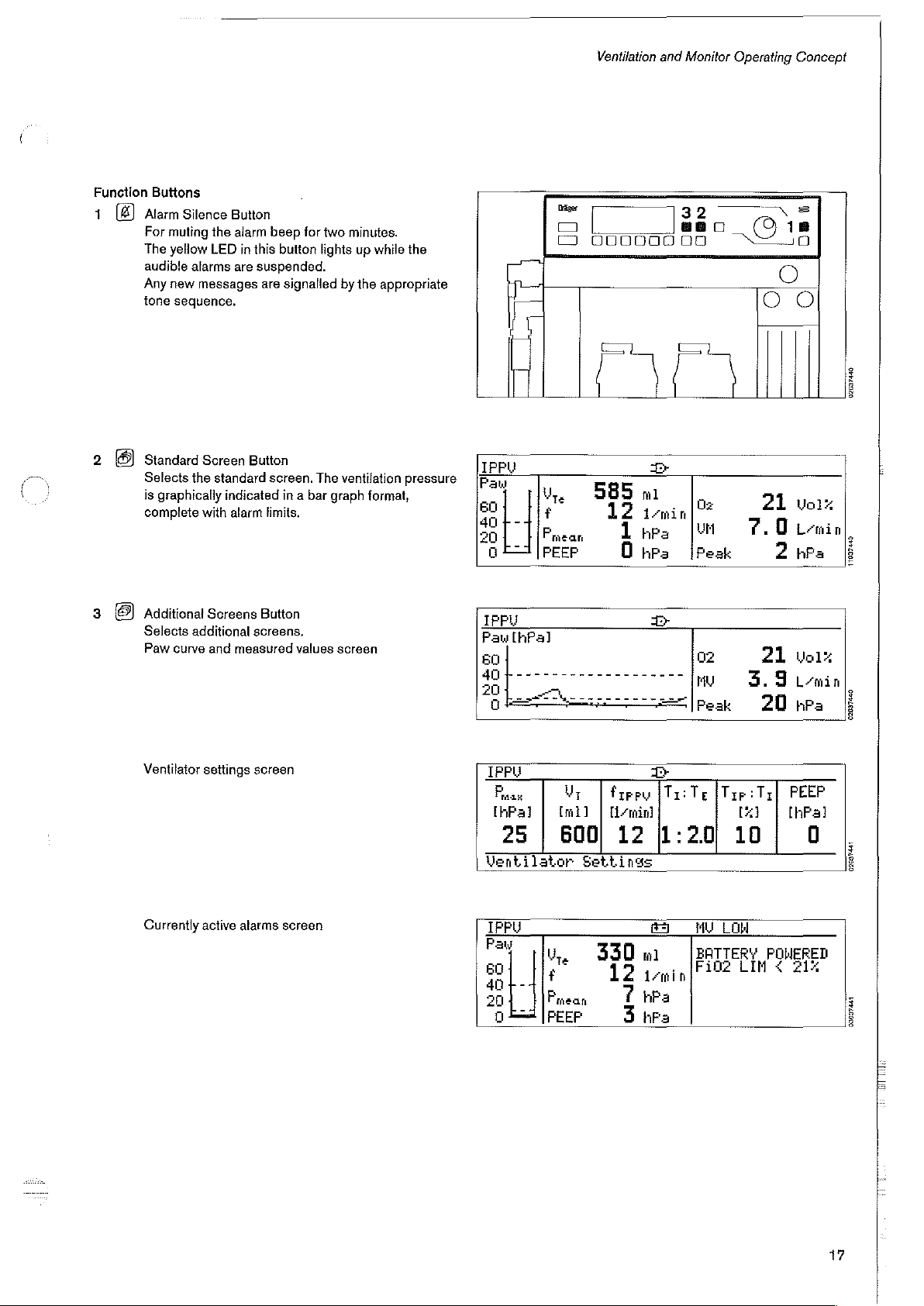
Function
1
Alarm
The
audible
Any
tone
Standard
Selects
is
complete
Buttons
Silence
For
muting
yellow
alarms
new
messages
sequence.
Screen
the
graphically
with
Button
the
alarm
LED
in
this
are
suspended.
Button
standard
indicated
alarm
beep
button
are
signalled
screen.
in a bar
limits.
for
two
lights
The
by
graph
minutes.
up
while
the
the
appropriate
ventilation
pressure
format,
IPPU
Paw
so)
401-41
20
1
İle”
Fran
a
器
O
Ventilation
000000008
5
1
O
т
ismin
hPa
hpa
585
and
Monitor
88
0
[=
|
μή
[Peak
Operating
0
18
21
7.0
ㆍ
2
Concept
vox
1
Lemin
hPa
02037440
11937440
3
Additional
8
Selects
Paw
Ventilator
Currently
Screens
additional
curve
and
settings
active
Button
screens.
measured
screen
alarms
screen
values
screen
IPPU
[hPa]
Pau
IPPU
|
Pau
[hPa]
25 | 600!
|
Mentilator
TFPu
Pay
ent
an
20
n
Mr.
[ml]
|
Settings
Le
L-
f
Paean = È
4IFEEF
|
330
B
>
¡Tao
#zrey
[min]
12
1:20
#3
m . [Fine
ismin
hPa
hs
02
ryu
Peak
Te
МУТОН
BATTERY
3.9
:Tz|
{Typ
Lx]
10
LIM < 21%
Vol:
21
min
hPa
20
PEEP
[hPal
0
POHERED
02097480
02099447
03097441
17
TA
Page 18
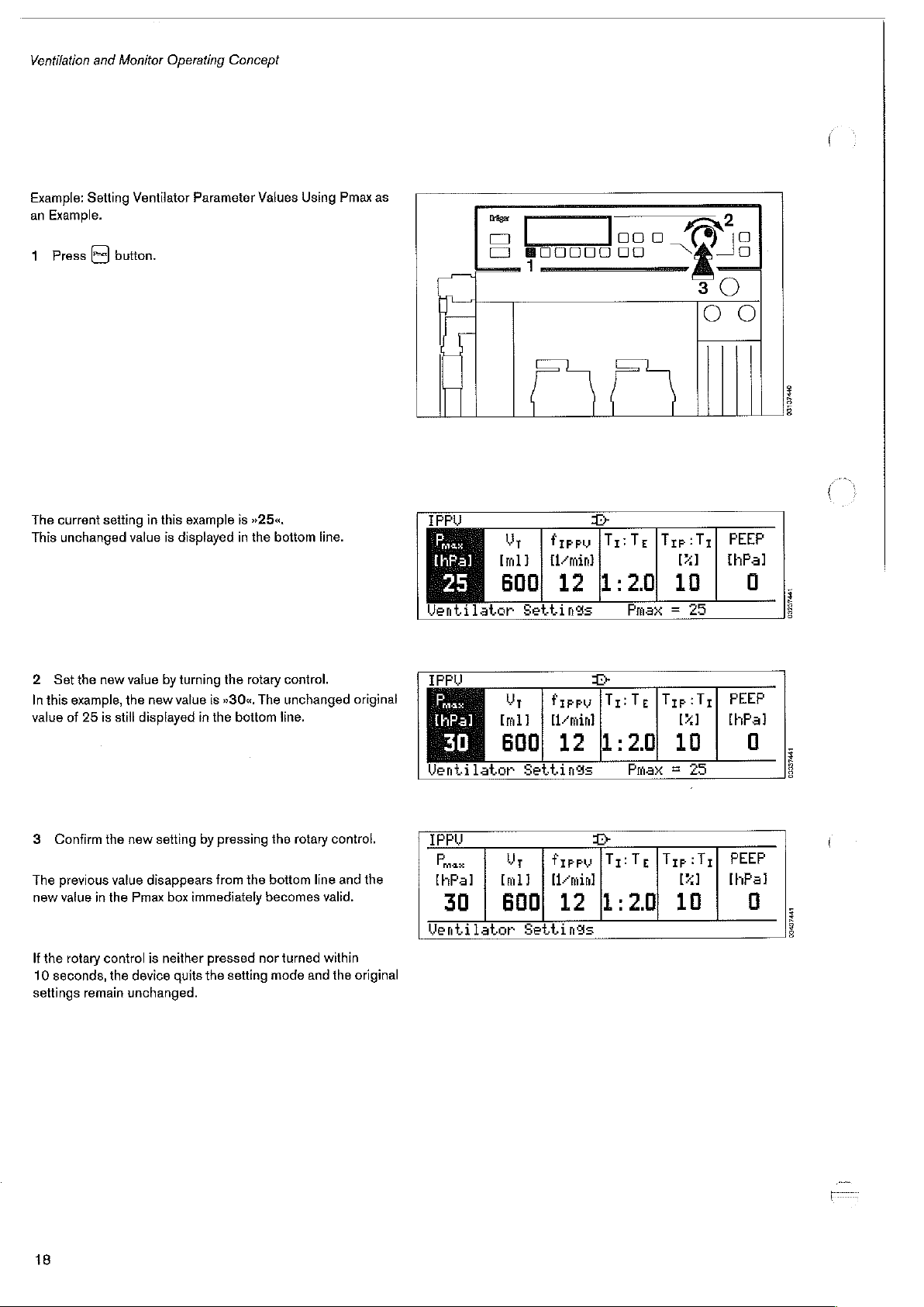
Ventilation
Example:
an
1
The
This
and
Setting
Example.
Press
current
unchanged
Monitor
Ventilator
button.
setting
value
Operating
in
this
is
displayed
Concept
Parameter
example
is
»25«.
in
the
Values
bottom
Using
line.
Pmax
as
Ventilator
Bager
O
DI
00000
Fiera
Amin]
12
Settings
noo
06
ロロ
T+
Ta:
1:20
0
_&—1
Te
[Τρ
:Ττ
[1]
10
Prax = 25
a
30
OO
Il
PEER
[hPa]
03137440
0
09227431
2
Set
the
In
this
example,
value
of
3
Confirm
The
previous
new
value
If
the
rotary
10
seconds,
settings
new
25
is
still
the
value
in
the
control
the
remain
value
by
turning
the
new
value
displayed
new
setting
disappears
Pmax
box
is
neither
device
quits
unchanged.
the
rotary
is
»30«.
The
in
the
bottom
by
pressing
from
the
immediately
pressed
the
nor
setting
control.
unchanged
line.
the
rotary
bottom
becomes
turned
mode
and
control.
line
and
valid.
within
the
original
the
original
НЫ
[hPa]
Ventilator
IPPU
Fax:
[hFal | [ml] | [min]
Ventilator
30 | 600)
Settings
Ут | Pree
Settings
Pirro
[min]
12
12
T
Tr:
1:20
T+
[Tri
1:
2.0
Te
[Trp:Tr|
[X]
10
Prax = 25
Te | Trp:
Tr}
[x]
10
PEEP
[hPa]
PEEP
[hPa]
0
03937441
0
09437441
18
Page 19
Ventilation
and
Monitor
Operating
Concept
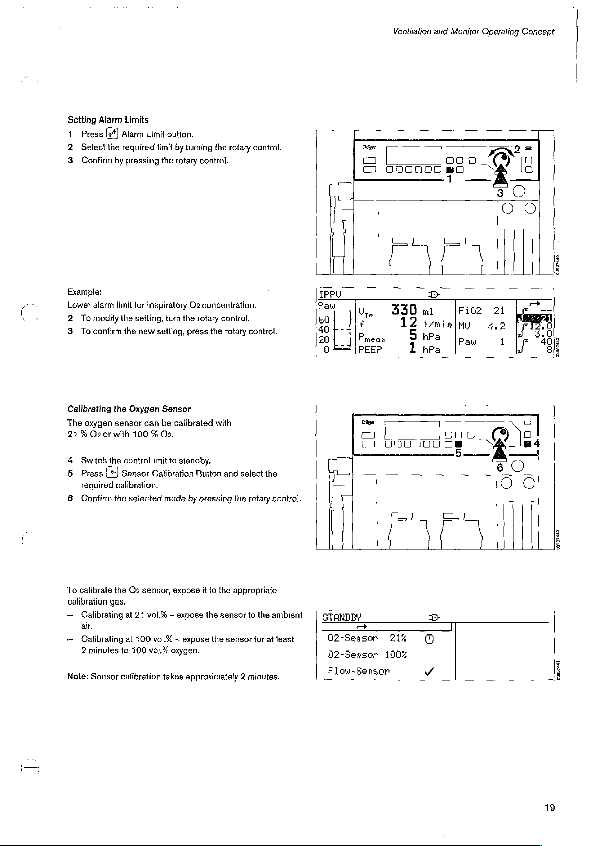
Setting
1.
2
3
Alarm
Press
[+]
Select
the
Confirm
Limits
Alarm
required
by
pressing
Limit
button.
limit
the
by
turning
rotary
the
rotary
control,
control.
Dés
O
σα
090000
口 口 口
BO
Fe
<Q
So
3
==
D
〇
ο ο
la,
#
Fmeas
PEEP
Trigo
0
O
330m
|
UO0NDOCO
12
i-min
5
hPa Paw
1
hPa
|
>
[rioz
HU
O
ao
5
Example:
Lower
alarm
limit
for
inspiratory
X
2
To
modify
3
To
confirm
Calibrating
The
21%
4
Switch
5
Press
required
6
Confirm
the
oxygen sensor
O2
or
with
the
the
setting,
the
new
setting,
Oxygen
can
100 % O2.
contro!
unit
Sensor
Calibration
calibration.
the
selected
O2
turn
the
press
Sensor
be
calibrated
io
standby.
mode
by
concentration.
rotary
control.
the
rotary
control.
with
Button
and
select
pressing
the
rotary
the
control.
IPPU
Pav
21
4,2
1
(9
6
ο ο
jal
O
03537440
03897440
To
calibrate
calibration
ー
ー
Note:
gas.
Calibrating
air.
Calibrating
2
minutes
Sensor
the
O2
sensor,
at
21
vol.% — expose
at
100
vol.% — expose
to
100
vol.%
calibration
expose
it
to
the
appropriate
the
sensor
the
sensor
oxygen.
takes
approximately 2 minutes.
to
the
for
ambient
at
least
STANDBY
02-Sensor
D2-Sensor
Flou-Sensor
다
aix
1
údy
09037441
19
Page 20
Ventilation
and
Monitor
Operating
Concept
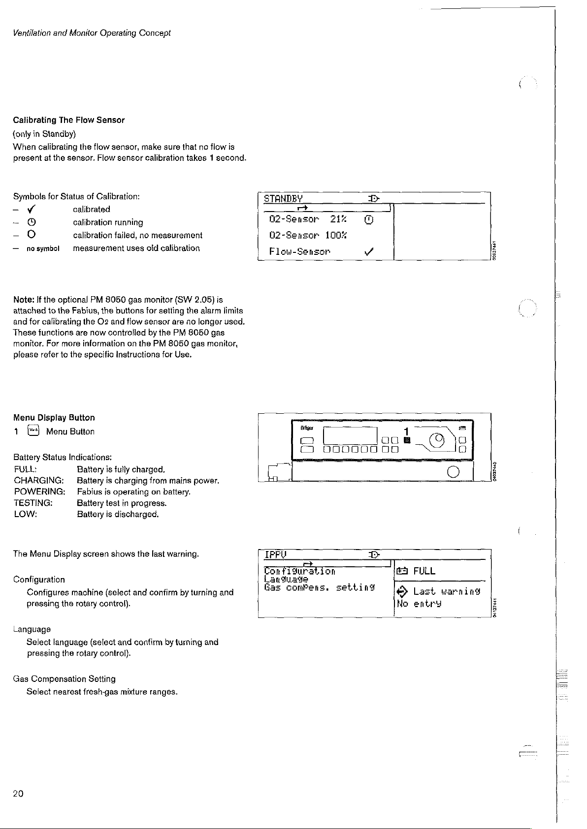
Calibrating
{only
in
Standby)
When
calibrating
present
Symbols
ー
-
-
—
Note:
attached
and
These
monitor.
please
at
the
for
ザ
0
0
nosymbol
if
the
optional
to
the
for
calibrating
functions
For
refer
The
Flow
Sensor
the
flow
sensor.
Status
more
to
Flow
of
Calibration:
calibrated
calibration
calibration
measurement
PM
Fabius,
the
the
O2
are
now
information
the
specific
sensor,
failed,
8050
and
controlled
make
sensor
running
no
uses
old
gas
monitor
buttons
flow
sensor
on
the
Instructions
sure
that
calibration
measurement
for
by
PM
takes 1 second.
calibration
(SW
2.05)
setting
the
are
no
the
PM
8050
8050
gas
for
Use.
no
flow
is
alarm
longer
gas
monitor,
is
limits
used.
STANDEY
+
D2-Senzor
Q2-Sensor
Flow-Sensor
212
100%
om
vč
ση
Menu
Display
1
6-3
Battery
FULL:
CHARGING:
POWERING: _ Fabius
TESTING:
Low:
The
Menu
Configuration
Configures
pressing
Language
Select
pressing
Gas
Compensation
Select
Menu
Status
Display
the
language
the
nearest
Button
Button
Indications:
Battery
Battery
Battery
Battery
screen
machine
rotary
(select
rotary
Setting
fresh-gas
is
fully
charged.
is
charging
is
operating
test
in
progress.
is
discharged.
shows
(select
and
control}.
and
confirm
control).
mixture
from
on battery.
the
last
warning.
confirm
by
ranges.
mains power.
by
turning
turning
and
and
Pes
DI
O
IPPU
Configuration
Laru
zde
Gas
comPens.
|
000000
oo
look.
.
setting
T+
00
83
E
©
Ho
17
FULL
Last
entry
D
©
0
warning
N
DO
64027420
04137551
20
Page 21
Ventilation
and
Monitor
Operating
Concept
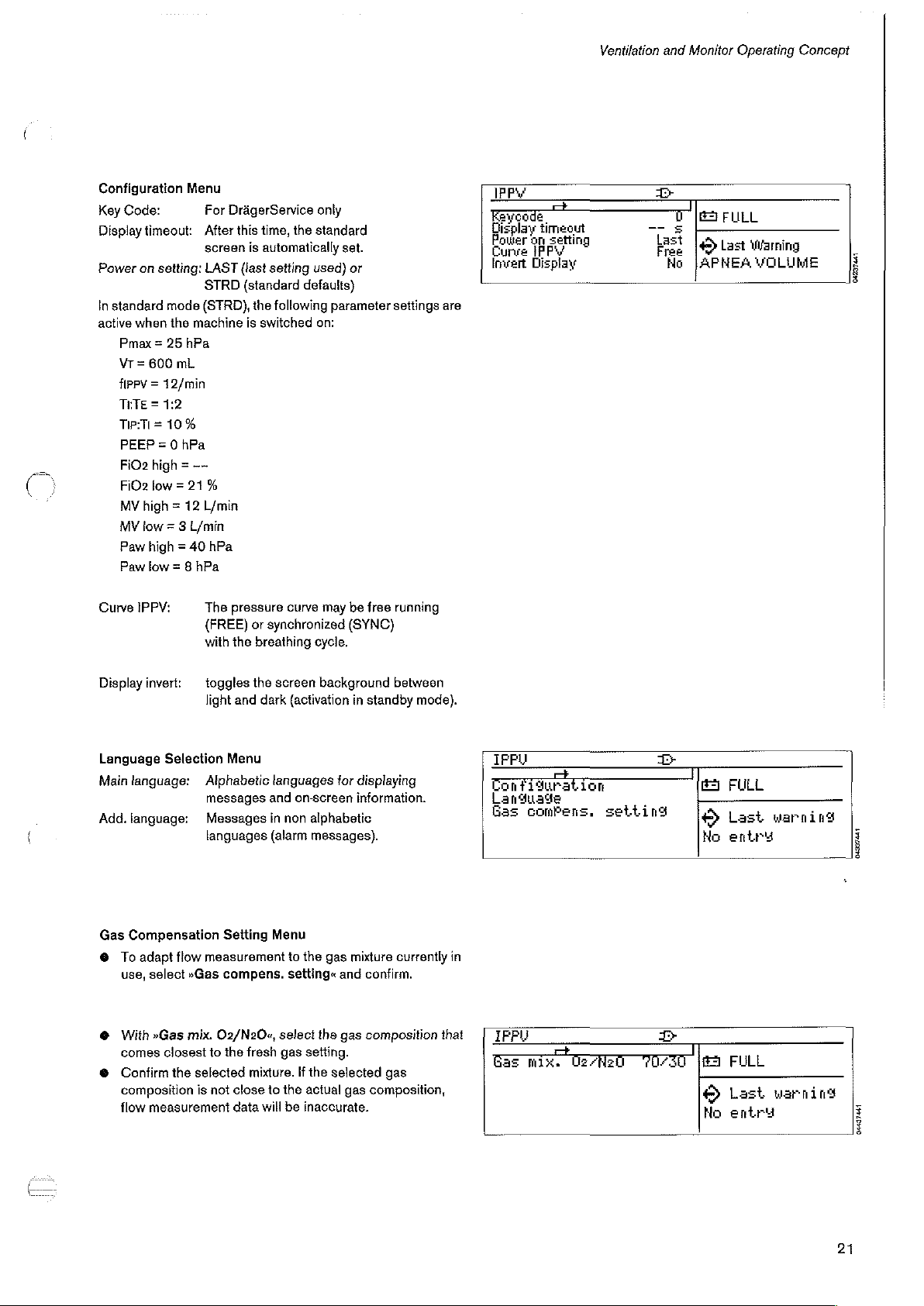
Configuration
Key
Code:
Display
timeout:
Power
on
setting:
In
standard
active
Pmax = 25
VT = 600
flppv = 12/min
ТЕТЕ = 1:2
TipiTi=
PEEP = 0
FiO2
FiO2
MV
MV
Paw
Paw
Curve
mode
when
the
10%
high = ——
low=
high = 12
tow = 3
high = 40
low
IPPV:
Menu
machine
hPa
mL
hPa
21%
L/min
= 8
hPa
For
DrägerService
After
this
time,
screen
is
automatically
LAST
(last
STRD
(standard
(STRD),
L/min
The
(FREE)
with
hPa
pressure
the
the
is
switched
or
breathing
only
the
standard
set.
setting
used)
defaults)
following
synchronized
on:
curve
cycle.
parameter
may
or
be
free
(SYNC)
settings
running
are
IPP
eycode
Display
timeout
peer
ap
Invert
Display
se
seria
Er
n
ES
5
test
[tact
No
JAPNEA
FU
FULL
+
waning
VOLUME
|
È
8
Display
Language
Main
Add.
Gas
©
e
e
invert:
language:
language:
Compensation
To
adapt
use,
select
With
comes
Confirm
composition
flow
measurement
Selection
flow
»Gas
»Gas
mix.
closest
the
selected
is
toggles
light
Alphabetic
measurement
the
and
dark
Menu
messages
Messages
languages
Setting
compens.
D2/N20«,
to
the
fresh
mixture.
not
close
data
will
screen
languages
and
in
(alarm
Menu
to
background
(activation
tor
on-screen
non
alphabetic
messages).
to
the
gas
setting«
select
the
gas
setting.
If
the
selected
the
actual
be
inaccurate.
between
in
standby
displaying
information.
mixture
currently
and
confirm.
gas
composition
gas
gas
composition,
mode).
in
that
IFPU
Configuration
Language
Gas
comPens,
IPP
as
mix.
setting
Üz”fiz
©
BI
-一
<>
©
Ho
E
©
No
FULL
Last
entry
FULL
Last
entry
warning
i
é
warning
04437441
.
D
E
21
Page 22
Preparation
Preparation
Caution
Prior
equipment
fastened
door
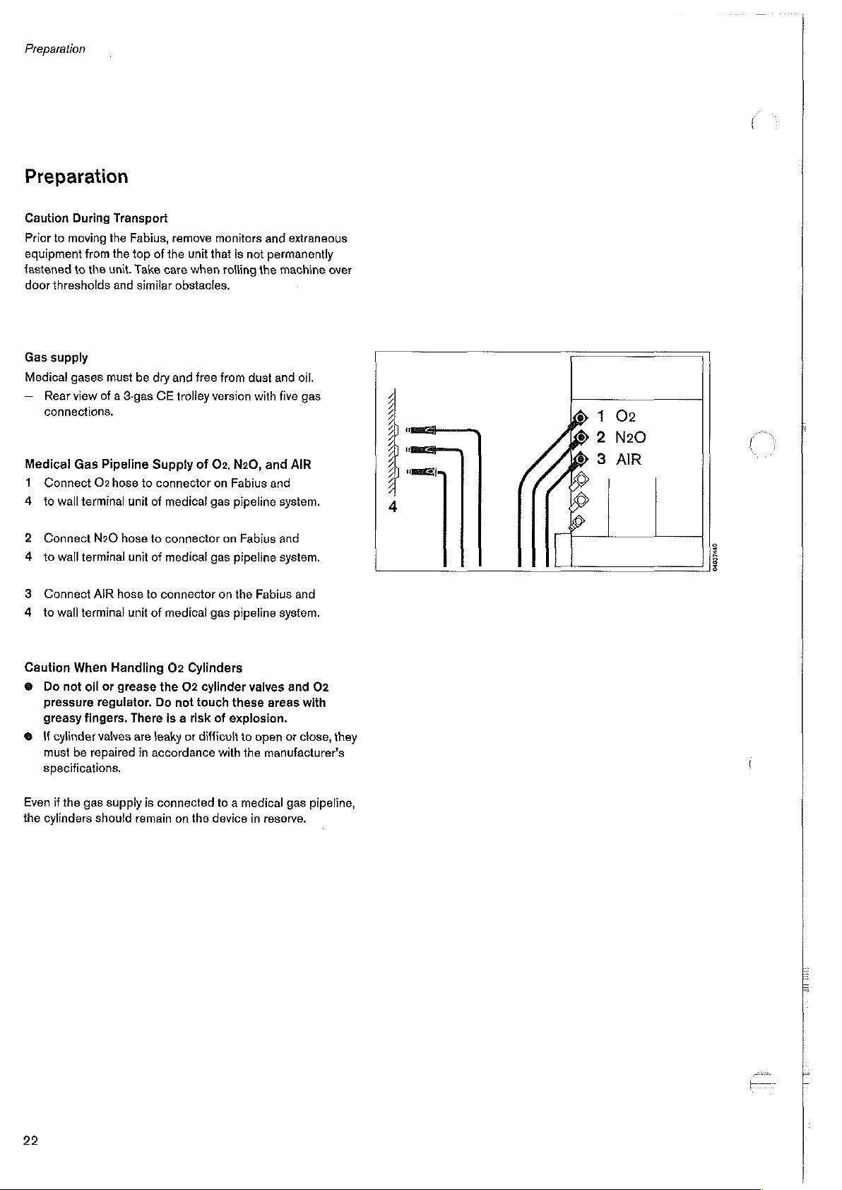
Gas
Medical
—
Medical
1.
4
2
4
3.
4
During
to
moving
to
thresholds
supply
gases
Rear
view
connections.
Conneot
to
wall
Connect
to
wall
Connect
to
wall
Transport
the
from
the
the
unit.
and
must
of a 3-gas
Gas
Pipeline
O2
hose
terminal
N2O
terminal
AIR
terminal
Fabius,
top
Take
similar
be
to
unit
hose
unit
hose
unit
remove
of
the
unit
care
obstacles.
dry
and
CE
trolley
Supply
connector
of
medical
to
connector
of
medical
to
connector
of
medical
that
when
free
of
gas
gas
gas
monitors
is
not
rolling
from
dust
version
with
O2,
N20,
on
Fabius
pipeline
on
Fabius
pipeline
on
the
pipeline
and
extraneous
permanently
the
machine
and
oil.
five
gas
and
AIR
and
system.
and
system.
Fabius
and
system.
over
©
1
02
ASS
SSAA
A
2
N20
(©
0
3
AIR
O O
04037480
Caution
©
©
Even
the
When
Do
not
oil
pressure
greasy
fingers.
{f
cylinder
must
be
repaired
specifications.
if
the
gas
cylinders
Handling
or
grease
regulator.
There
valves
are
in
accordance
supply
is
should
remain
O2
Cylinders
the
O2 cylinder
Do
not
touch
is a risk
leaky
or
difficult
connected
on
the
valves
these
areas
of
explosion.
io
open
with
the
manufacturer's
to a medical
device
in
reserve.
and
O2
with
or
close,
gas
pipeline,
they
22
Page 23
Preparation
Cylinders
On
@
@
e
©
The
manually.
Cylinders
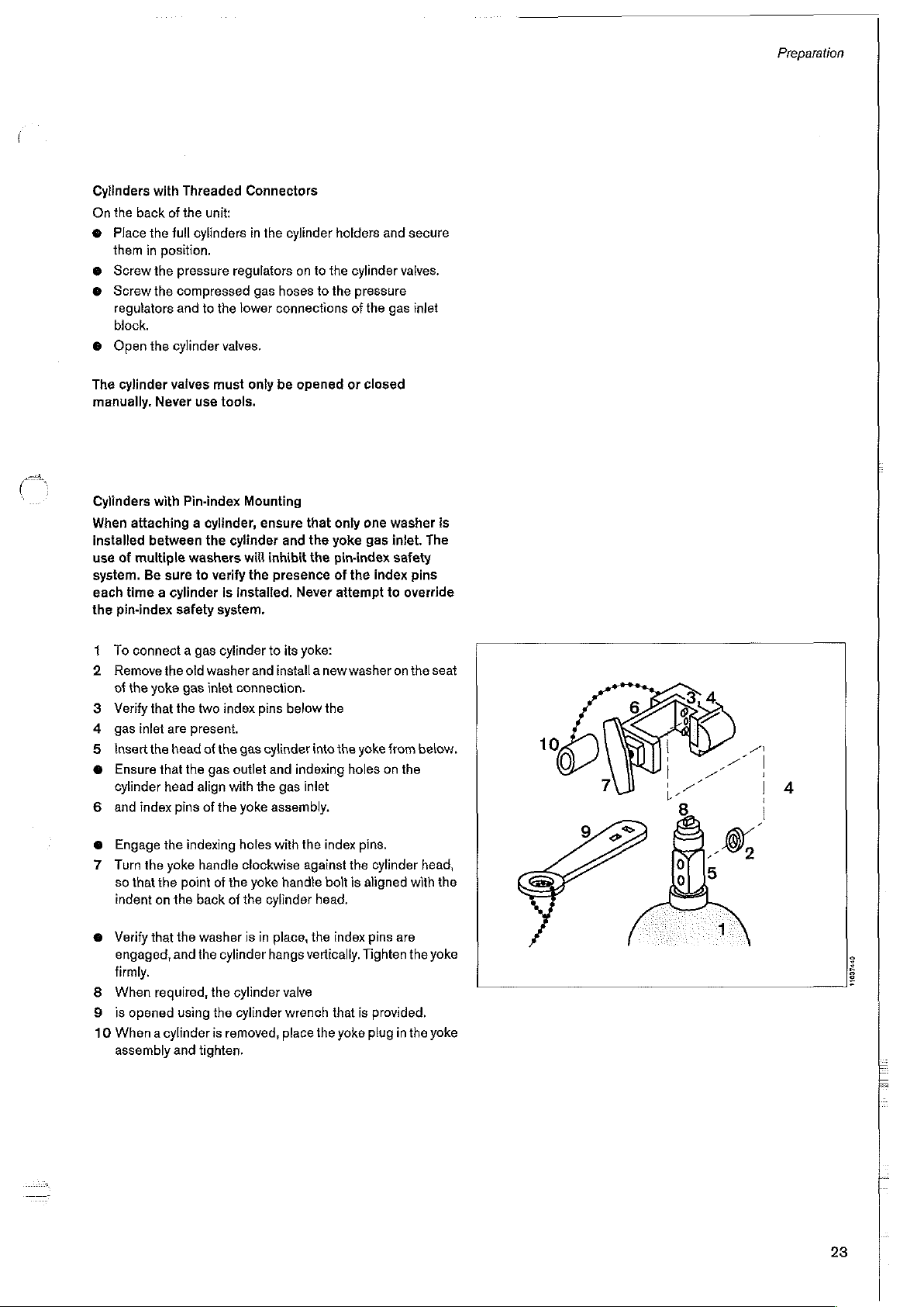
When
installed
use
system.
each
the
1
N
ea bw
6
with
the
back
of
Place
the
full
them
in
position.
Screw
the
Screw
the
compressed
regulators
block.
Open
cylinder
of
time a cylinder
pin-index
To
Remove
of
the
Verify
gas
Insert
Ensure
cylinder
and
and
the
cylinder
vaives
Never
with
attaching a cylinder,
between
multiple
Be
sure
safety
connect a gas
the old
yoke
that
the
inlet
are
the
head
that the
head
index
pins
Threaded
the
unit:
cylinders
pressure
to
the
valves.
must
use
tools.
Pin-index
the
washers
to
verify
is
system.
cylinder
washer
gas
intet
two
index
present.
of
the
gas
align
with
of
the
Connectors
in
the
cylinder
regulators
gas
hoses
lower
connections
only
be
Mounting
ensure
cylinder
outlet
and
will
inhibit
the
presence
installed.
to
its
and
install a newwasher
connection.
pins
below
gas
cylinder
and
the
gas
yoke
assembly.
holders
on
to
the
to
the
opened
that
only
the
yoke
the
pin-index
of
Never
attempt
yoke:
the
into
the
indexing
inlet
and
cylinder
pressure
of
the
gas
or
closed
one
washer
gas
inlet.
safety
the
index
to
on
yoke from
holes
on
secure
valves.
inlet
is
The
pins
override
the
seat
below.
the
Engage
7
Turn
so that
indent
©
Verify
engaged,
firmly.
8
When
9
is
10
When a cylinder
assembly
the
the
the
on
that
required,
opened
yoke
indexing
handle
point
the
back
the
washer
and
the
using
and
tighten.
holes
clockwise
of
the
yoke
of
the
is
cylinder
the
cylinder
the
cylinder
is
removed,
with
the
handle
cylinder
in
place,
hangs
valve
wrench
place
index
pins.
against
the
cylinder
bolt
is
aligned
head.
the
index
pins
vertically.
the
that
yoke
Tighten
is
provided.
plug
with
are
the
in
the
head,
the
yoke
yoke
31837440
23
Page 24

Preparation
Electrical
Fabius
127
socket!
@
1
Equipotential
For
Troltey-mounted
2
e
Supply
can
be
operated
V.
Observe
Push
Switch
the
machine.
intra-cranial
Use
cable
Connect
equipotential
power
on
the
the
the label
plug
Bonding
and
ref,
at
mains
beside
into
main
machine.
anesthesia
83
terminal
bonding
The
intra-cardiac
01
349
on the
point
voltages
the
mains
supply
on/off
operations
machines:
cable.
back
of
in
the
from
voltage
socket.
switch
is
the
trolley
operating
100 V to
input
on
the
rear
to
an
room.
of
Bi
1
(mL)
ev
¥
“fr?
©
B
mx
05037450
Pin
Index
version
05197440
06237440
24
Page 25

Preparation
Attaching
e.g.,
Resutator
©
Hang
right.
Preparing
Use
only
disinfected/sterilized
Swing
a
Unlock
@
remove
ON
Insert
Fit
the
BPN
lock
both
+
Swing
Manual
2000
the
fully
the
Ventilator
out the
the
clasps
the
cover.
the
diaphragm.
cover
and
locking
the
ventilator
Ventilation
for
emergency
prepared
ventilator
and
door.
to
screws.
unit
back
Bag
ventilation
tested
bag
components.
into
position.
on
the
rail
at
the
000
OOO)
Fabius
05997440
Ventilator
A
Over
pressure
B
Additional
Safety
air
Feature
valve
valve
06457440
25
Page 26

Preparation
Fitting
the
Breathing
©
Fill
the
recommends
@
Tighten
compact
©
Ensure
deposited
Such
Fitting
the
1
Place
2
Fit
the
3
Tighten
CO2
Absorber
System
absorber
the
the
absorber
breathing
that
no
CO2
between
dust
and
particles
Inspiratory
the
valve
disc
inspection
the
retaining
with
fresh
use
of
by
system.
absorbent
the
Valve
in
the
cap
(with
nut
on
the
Compact
CO2
absorbent.
Dragersorb®
turning
it
to
dust/particles
gaskets
and
can
cause
valve
seat.
port).
securely.
800
the
right
the
sealing
leaks
Drager
Plus.
in
the
into
the
have
been
surfaces.
system.
06537440
Fitting
4
Place
5
Fit
the
6
Tighten
Fitting
7
Tighten
the
Only
use a valve
the
Expiratory
the
valve
disc
inspection
the
the
Pressure-limiting
the
retaining
cap.
retaining
pressure-limiting
nut.
marked
Valve
in
the
nut
with
valve
seat.
securely.
Valve
valve
securely
"SPONT/IPPV"
into
and
place
"MAN".
with
05637440
26
08737440
Page 27

Preparation
Inserting
1
Unscrew
2
Insert
flow.
Fitting
the
3
Screw
system
Connecting
@
The
sealing
must
be
@
Only
hand-tighten
tools.
€
Slightly
system.
4
Fit
the
anesthesia
©
Tighten
the
Flow
and
the
flow
Waste
the
waste
from
underneath.
the
Compact
rings
undamaged
loosen
compact
machine.
the
knurled
Sensor
remove
sensor,
Gas
Outlet
gas
on
the
and
the
the
knurled
breathing
screw.
the
expiration
observing
Port
port
into
Breathing
threaded
clean.
threaded
screw
system
port.
the
indicated
the
compact
System
and
conical
connectors.
on
the
compact
to
the
pin
direction
breathing
connectors
Do
not
use
breathing
on
the
.
of
05837440
05937440
5
Screw
breathing
6
Screw
compact
7
Plug
expiration
the
fresh
system.
the
ventilation
breathing
the
control
valve
gas
system.
hose
and
hose
to
hose
to
to
the
the
connection
the
Fabius
the
ventilator
connection
port
and
to
and
port
on the
the
compact
to
the
on
the
ventilator.
95097440
27
Page 28

Preparation
Fitting
Microbial
@
Push
the
expiratory
Dismantling
@
Squeeze
pull
the
filter
Condensation
filters,
making
Carefully
Observe
filter.
Connecting
Note:
@
©
—
@
monitor
the
Take
care
When
connecting
breathing
reinforcement.
torn
loose,
Breathing
kink,
thereby
Before
each
Filters
microbial
port,
instructions:
at
specific
the
not
hoses
hoses
filters
until
they
the
points
marked
off
the
port.
may
increase
breathing
the
airway
Instructions
Breathing
to
damage
and
by
the
Otherwise,
e.g.
at
the
end-sleeve.
with
damaged
interrupting
use,
check
more
disconnecting,
into
the
noticeably
"PRESS"
the
flow
difficult.
pressure.
for
Hoses
the
breathing
end
sleeve,
the
spiral
spiral
breathing.
the
breathing
inspiratory
click
resistance
Use
not by
reinforcement
port
into
and
simultaneously
for
the
microbial
hoses.
always
the
reinforcement
hoses
for
and
place.
of
the
hold
the
spiral
may
damage.
can
be
00137440
1
Push a patient
cone
and
2
Connect
3
Connect
hose
via
4
Connect
breathing
the
expiratory
both
the
manual
the
double
the
bag
system.
breathing
patient
breathing
breathing
port.
hose
to
hose
cone
the
on
to
or
on
hoses
bag
elbow
both
to
the
to
the
port
the
microbial
to
the
Y-piece.
bag
on
the
inspiratory
filters.
breathing
compact
06207440
06337440
28
Page 29

Preparation
Connecting
1
Push
the
and
2
plug
in
Connecting
3
Press
socket
until
it
the
O2
O2
sensor
the
connector
the
Pressure
the
probe
on
the
underside
engages.
Sensor
into
of
the
Capsule
the
port
on
the
back
Sensor
pressure
of
the
of
the
of
the
measuring
compact
inspiratory
control
breathing
line
valve,
unit.
into
system
the
96437440
4
Connect
bacterial
the
the
filter
control
hose
and
unit.
of
the
plug
pressure
it
firmly
measuring
into
the
port
line
on
to
the
the
back
of
08597440
29
Page 30

Preparation
Connecting
1
Push
the
the
flow
Please
the
Flow
measuring
sensor
note
the
Sensor
hoses
on
and
at
the
back
connections
to
the
of
the
are
different.
connection
unit.
ports
on
00037440
30
Page 31

Preparation
Connect
For
use
Screw
må
Connect
Connect
ON
Plug
Connect
Aah
Connect
connector.
For
use
@
Remove
@
Use
@
Plug
the
Magill
with
mask:
Magill
breathing
breathing
ISO
mask
mask
sampling
with
tube:
ISO
mask
ISO
connector.
connector
Inhalation
connector
bag.
hose E (110
connector
io
ISO
mask
hose
connector.
for
tracheal
Device
onto
the
into
breathing
connector.
for
monitoring
tube
freshgas
cm).
to
into
ISO
outlet.
hose.
the
Magill
connector.
00037440
Caution:
The
the
Magill
Fabius
Circuit
shall
ventilator,
not
be
connected
to
11737440
31
Page 32

Preparation
Connecting
inserting a new
Unscrew
1
Remove
e
a
2
Insert
conductor
Screw
installing
Compact
Connect
Compact
scavenging
A
compact
the
the
the
disinfected
the
the
Anesthetic
Breathing
the
Breathing
second
breathing
O2
Sensor
O2
sensor
screw
new
sensor
sensor
capsule
transfer
against
screw
cap
System
transfer
line
or
in
Gas
hose
capsule:
cap
from
capsule
capsule.
the
housing,
the
contacts
on
firmly
Scavenging
hose
System
an
anesthetic
is
required
system.
to
and
the
in
by
the
sensor
from
its
with
the
housing.
hand.
Hose
waste
to
the
agent
for
housing.
packaging,
the
ring-shaped
to
the
gas
port
of
anesthetic
filter.
the
Semi-open
or
the
gas
use
N
wk
07037440
|
07137440
32
Page 33

Preparation
Anesthetic
1
Oufput
2
Connection
outlet
3
Flow
indicator.
between
4
Connection
For
more
detailed
to
the
specific
Scavenger
Semi-open
Both
exhaust
5
one
on
6
the
other
must
be
connected
Remove
the
Gas
Scavenging
connection
to
scavenger
port.
During
the
upper
for
Semi-open
information
Instructions
System
Compact
ports
the
semi-open
on
the
existing
System
from
the
system
use,
the
and
lower
breathing
on
for
Use.
Connections
Breathing
adapter
Compact
to
scavenger
the
Breathing
AGS
AGS
scavenging
from
Fabius
flow
indicator
marks
on
system.
the
scavenging
for
the
System
and
System
scavenger.
plug
if
necessary,
system.
waste
must
the
tube.
system,
housing
be
gas
refer
17097440
A-Cone
7
The
the
the
8
The
alternate
9
The
the
the
Switch
A-Cone
conical
Fabius.
horizontal
lower
Compact
Fabius.
switch
fitting.
breathing
vertical
or
is
connected
it
must
port
of
the
system.
port
of
Semi-open
be
mounted
A-Cane
the
A-Cone
Compact
to
the
parallel
switch
switch
breathing
fresh
gas
to
is
connected
is
connected
outlet
the
front
to
system
via
of
the
to
on
07337440
σαι
lago
00060000
a
0)
O
ay
“ble
[o_o
Fabius
t=
33
07437440
Page 34

Preparation
Installation
Disconnect
Disconnect
Close
all
Remove
Compact
Remove
Noo
Remove
Loosen
Breathing
Gently
lift
a
firm
surface.
surface
Remove
washers
breathing
Ensure
that
mount,
Store
this
absorbent
of
the
Semi-Open
the
the
Fabius
gas
cylinders
all
hoses,
Breathing
the
APL
the
absorbent
the
locking
System
the
breathing
It
such
as a towel
the
three
that
hold
system
all
"O"
mount
canister.
Fabius
from
from
(if
sensors,
System.
valve.
canister
screw
to
the
mounting
system
is
recommended
to
mounting
the
canister
housing.
rings
are
assembly,
Adapter
the
mains
power
the
central
applicable).
and
control
and
store
that
secures
stud.
and
place
that
it
prevent
marring
screws
(M 5 x
mount
removed
hardware,
to
with
and
supply.
pipeline
the
be
lines
from
properly.
Compact
upside
placed
of
the
16
mm)
the
compact
the
canister
"O"
rings
gas
supply.
the
down
on
on a soft
unit.
and
with
the
07537440
34
0763740
Page 35

Preparation
Prepare
Ensure
~
These
the
not
Place
and
secure
the
These
and
first
belleville
be
these
Place
the
Connect
Install
Connect
pipeline
the
that
"O" rings
"O"
rings
interchangeable.
the
with
adapter.
screws
four
followed
installed
screws.
the
Fabius
the
gas
semi-open
the
"O"
rings
are
from
the
adapter
belleville
style
semi-open
all
APL
Fabius
the
three
each
by
the
washer
by
opposing
and
secure
hoses,
valve.
supply.
onto
come
washers.
sensors,
to
the
adapter.
are
provided
compact
the
compact
screws
with a flat
The
flat
washer.
is a curved
each
adapter
the
locking
and
mains
in
the
proper
with
the
canister
breathing
provided
washer
belleville
Please
spring
other.
Do
back
on
the
screw.
contro)
powers
supply, and
position.
adapter.
mount,
(M 5 x
80
and
washers
note
that
washer
not
over
mounting
lines.
Do
not
use
as
they
are
assembly
mm)
with
go
on
the
and
must
tighten
pole
central
of
07737440
Removing
Installing
Disconnect
Disconnect
Close
Remove
Compact
Remove
Loosen
Breathing
Gently
a
firm
Itis
recommended
as a towel
Remove
washers
to
the
the
Semi-Open
the
CO2
the
the
all
gas
cylinders
all
hoses,
Breathing
the
APL
the
locking
System
lift
the
breathing
surface.
to
prevent
the
three
that
hold
compact
Adaptor
Absorber
Fabius
from
Fabius
from
(if
sensors,
System.
valve.
screw
to
the
mounting
system
that
it
marring
mounting
the
semi-open
breathing
and
the
mains
the
central
applicable).
and
contro!
that
secures
stud.
and
place
be
placed
on a soft
of
the
unit.
screws
(M 5 x
breathing
system
housing.
power
supply.
pipeline
lines
the
upside
gas
from
Compact
surface
80
mm)
system
supply.
the
down
on
such
and
adapter
07697440
35
Page 36

Preparation
1
Ensure
canister
2
Install
washers
breathing
3
There
4
atlat
belleville
be
installed
installed
5
Gently
stud,
e
Connect
6
Install
e
Connect
pipeline
7
Install
CO2
that
all
five
mount.
the
three
that
hold
system
are
three
washer
for
style
washer
by
opposing
next.
Do
liftthe
breathing
Tighten
absorbent、
all
the
APL
Fabius
gas
the
absorbent
the
hoses,
valve.
supply.
"O" rings
mounting
housing.
belleville
each
not
mounting
to
the
canister
mounting
is a curved
over
system
sensors,
the
mains
canister.
screws
washers
each
tighten
are
in
the
mount
screw.
other.
and
screw.
and
control
powers
Ensure
proper
(M 5 x
to
and
Please
spring
The
these
place
supply,
it
is
position
16
mm)
the
compact
note
washer
flat
washer
screws.
it
on
the
lines.
and
filled
with
of
the
and
that
the
and
must
is
mounting
central
fresh
3
6
ο
©
ит
1
|
5
Ἵ
23
forge
07097480
_
Additional
Prepare
Instructions
Caution:
Caution:
36
Equipment
additional
for
If
monitors
of
increased,
etc.
the
Remove
top
equipment
Use.
Fabius,
Remove
top
of
all
of
the
as
and
other
the
risk
of
especially
all
monitors
the
Fabius
monitors
Fabius
before
specified
equipment
tipping
over
when
rolling
and
other
before
moving
and
other
moving
in
the
specific
are
placed
the
unit
over
thresholds
equipment
the
unit.
equipment
the
unit.
on
is
trom
top
from
the
L_
00007445
Page 37

Operation
Operation
Nitrogen
During
anesthesia
nitrogen
in
the
patient's
When
the
anesthesia
flushed
(02/N20)
Adjusting
1
with a time-limited
With
Set
fresh
Wash-out
(N2)
remains
lungs).
next
intended
case,
in
order
the
Fresh
the
metering
gas
(when
induction,
in
the
use
the
nitrogen
to
ensure
Gas
Composition
valves:
flow
for
O2,
Required)
air
containing
compact
of
the
content
high flow
correct
N20
and
about
79
breathing
unit
may
should
of
fresh
denitrogenization.
AIR.
system
be
for a low-flow
first
be
gas
%
(and
fp
Om
08197440
ピー
Setting
2
3
4
@
©
the
Vapor
Lock
the
unused
go
in
the
direction
hand
Vapor
Onthe
Vapor
and
at
the
Turn
the
handwheel
anesthetic
Regularly
reaching
agent.
Please
Drager-Vapor®,
the
refer
is
locked).
to
same
agent
check
minimum
to
be
time
the
the
Vapor
by
pushing
of
the
unused
Vapor
used,
press
and
counter-clockwise
concentration.
filling
level
on the
mark,
fill
the
specific
Instructions
the
lever
(in
hold
to
sight
Vapor
this
down
the
with
for
as
glass.
Use
far
as
it
will
example
the 0 button
desired
anesthetic
left
When
for
HRM
2
=
LÃ
NE
4
00237440
37
Page 38

Operation
Ventilation
Semi-open
There
are
three
—
Spontaneous
—
Manual
—
Automatic
Spontaneous
On
the
control
1
Pressthe
2
Confirm
3
Set
the
The
valve
Pressure
4
Administer
bag
on
Modes
Compact
ventilation
and
Breathing
unit
by
pressing
lever
on
is
now
cannot
enough
the
compact
with
the
Compact
Breathing
button.
the
the
pressure-limiting
open,
build
fresh
breathing
System
modes
available
rotary
control.
regardless
up
in
the
gas
to
system.
and
valve
of
the
compact
fill
the
manual
in
the
Fabius:
to
SPONT/IPPV.
set
pressure
breathing
ventilation
limit.
system.
e
milo
DO
000000
STI
M
1200
-İNOAS
一 一 一
00
NS
=
OY
a
0
ῇ
τση
σ
To
prevent
false
spontaneous
parameters:
—
Lower
alarm
—
Upper
alarm
If
other
alarm
page
19.
alarms,
breathing
limit
for
limit
for
limits
are
required,
the
monitoring
can
be
O2
Paw
reduced
see
"Setting
function
to
the
following
Alarm
during
Limits"
on
lle
Leal
ΠΠ
98457440
38
Page 39

Operation
Manual
On
the
1
Press
2
Confirm
3
Set
4
Set
desired
Administer
5
Ventilate
Ventilation
controf
unit
the
by
pressing
the
lever on
the
desired
value
is
sufficient
manually
button.
the
rotary
control.
the
pressure-limiting
pressure
indicated
fresh
with
limit
on
the
by
the
gas.
manual
valve
to
rotating
scale.
the
ventilation
MAN.
lever
bag.
until
the
Diğer
maf
OQ
E
i
Kansu
ロロ
ロロ
M
ロロ
889
©
O,
O
je
0
9697440
To
prevent
false
ventilation
—
—
If
other
page
Lower
Upper
alarm
19.
can
alarm
alarm
alarms,
be
reduced
limit
limit
limits
are
the
monitoring
to
tor
O2
tor
Paw
required,
the
following
see
function
parameters:
“Setting
during
Alarm
manual
Limits”
on
09697440
39
Page 40

Operation
Automatic
On
the
control
values:
1
Pmax;
Then
2
Press
3.
Confirm
—
The
IPPV
Ventilation
unit
set
VT;
f;
TETE;
the
by
button.
pressing
Confirmation
the
following
TIP:T!
and
the
Request
PEEP
rotary
control,
controls
screen
appears.
to
the
desired
STANDEY
10988
DI
|
Do
BBBBBE
——
1
ME
3
0
0 0
4
Set
the
3.
Confirm
Note:
If
the
user
position,
the
IPPV
IPPV
mode
are
momentarily
@
Administer
pressure-limiting
by
pressing
fails
to
confirm
the
mode
remains
button
on
the
front
is
treated
as a CAUTION,
lit
and
an
sufficient
valve
to
SPONT/IPPV.
the
ratary
control.
that
the
APL
as
it
was
before
panel. This action
audible
fresh
caution
gas.
valve
is
in
the
to
therefore
is
heard.
the
IPPV
user
pushed
select
yellow
the
LEDs
06087440
40
Page 41

Operation
Pressure
(PLV - Pressure
The
adjustable
At
Ventilation
At
»
©
@
Recommendation:
tidal
As
the
unblocked
still
When
not
The
ТЕТЕ;
Only
10%
limited
Fabius
CE
features
pressure
Pmax,
pressure
is
then
Pmax,
pressure
SetPmaxtothe
Set
the
tidal
sponding
volume
soon
pressure
present
excessively
inspiration
one
as
tube
making
ИРЛИ.
setting
to
actually
Pmax
remains
in
the
the
high,
flow
ventilation
Limited
volume
the
are
for
Ventilation)
an
limit
Pmax
limited
ventilation
volume
inconstant.
limited
ventilation
required
VT
patient's
Set
the
applied.
is
reached
constant
compensated,
ventilator
settings,
resulting
is
influenced
Tip:Ti
adjustable
inspiration
to a value
weight.
VT
in
is
directed
ensure
in a dynamic
is
allowed
applies
is
is
higher
to
e.g.
double
the
active
and
leaks,
At
the
that
by the
pressure
for
possible
possible
pressure,
into
the
in
limit,
the
expiration
in
(PLV).
e.g.
than
the
the
value
flow
phase
e.g.
due
same
time,
the
ventilation
inspiration
overshoot
parameters
the
range
The
valve.
IPPV
mode.
15
mbar.
VT
corre-
of
the
(TI — Tıp),
to
an
volume
flow
of
Pmax.
VT;
fi
from 5 to
[Pressure
Pmaxl
|Pressure
Pmax
bag.
js
...
.......
ーーーーーーー
--- — PPlat
1
i
CT
!
T
Va
TIP
que
fPPV
ーー
PPeak
IPPV
ited
Volume
TE
nn
IPPV
Volume
Pmax > PPeak
TN
constant
pressure
inconstant
し
!
|
lim-
も
122
Recommended
Compliance | fippy
patient
(mL/mbar)
50
50
50
50
5
5
5
5
parameter
10
10
10
10
25
25
25
25 11
settings
TETE
1:2
12
1:1
1:1
12
1:2
ti
Tip:Ti | SetPmax|
(%)
10
5
10 15
5
10 15
5
10 15
5
(mbar)
15
15
15
15
15
PEEP
(hPa)
5
5
5
5
5
5
5
5
Set
VT
(mL)
1000
1000
1000
1000
100
to
150
100
to
150
100
to
150
100
to
150
Effective
Pmax
(mbar)
19
19
17
17
15
15
15
15
Exp.
volume
(mL)
440
440
390
390
40
40
40
40
TATE
AMT
41
Page 42

Operation
Depending
compliance, a significant
possible
O
Set
Using
Note:
With
1
the
This
©
Ensure
©
Set
the
The
the
and
gas.
A
or
2
The
©
Switch
button
handwheel.
Drager
on
at
the
the
the Magill
the
Magill
relief
can
be a health
adequate
the
O2/N20
Fabius.
fresh
minute
the
associated
lower
fresh
shortage
breathing
on
and
Vapor®,
the
ventilator
expiration
alarm
limit
Breathing
system,
valve.
gas
flow
volume
gas
of
breathing
bag could
the
vaporizer.
select
Refer
"Paw
anesthetic
hazard!
ventilation.
fresh
must
in
order
accumulation
flow
the
desired
to
the
settings
overshoot
valve.
System
gas
be
could
gas.
deflate
Press
Instructions
(VT;
of
High"
to
gases
flow
on
equal
to
to
exclude
of
result
and
and
concentration
f;
Ti:
TE)
the
set
Pmax
Pmax + 5
escape
via
the
metering
at
least
2.5
the
risk
of
COz
in
the
in a partial
suffocate
hold
down
on
for
Use
of
and
patient
limit
is
mbar
|
valves
on
to 3 times
rebreathing
inspiratory
rebreathing
the
patient.
the
release
the
the
90097440
For
Spontaneous
1
Turn
result
2
Observe
spontaneous
For
Manual
1
Set
the
Seta
©
minimize
2
Ventilate
Caution:
Breathing
the
relief
valve
counterclockwise
in
minimum
movement
Ventilation
relief
correspondingly
the
via
The
connected
ventilation
of
breathing.
valve.
amount
the
breathing
Magill
Breathing
to
of
the
pressure,
the
breathing
high
fresh
rebreathed
bag.
System
Fabius
ventilator.
(fully
bag
to
gas
flow
in
expiratory
shall
not
open).
check
order
gas.
be
This
for
to
will
42
Page 43

Operation
A-Cone
—
Facing
top
is
towards
—
When
flow
—
The
ensures
thereby
atime.
Lever
Selection
the
A-Cone
of
the
A-Cone
the
the
lever
is
towards
selector
that
ensuring
lower
is
the
lever
the
switch
the
switch,
when
switch)
is
vertical
moved
to
horizontal
for
the
A-Cone
is
either
flow
of
to
the
port.
the
left
port.
fresh
the
lever
right,
position,
is
spring
in
the
right
gas
to
(located
the
fresh-gas
the
loaded
or
left
only
one
on
the
flow
fresh-gas
and
position
port
at
(=
i
08237430
02 Flush
1.
Press
—
About
system
anesthetic
@
Make
unacceptably
the
50
and
sure
O2
Flush
L/min
to
the
agent
that
high.
button.
O2
flows
patient.
vaporizer
the
airway
into
the
compact
The
flowmeter
(Vapor)
pressure
are
bypassed.
does
breathing
block
and
not
rise
the
に
レー
©)
10
DOG
00337440
43
Page 44

Operation
Replacing
©
The
CO2
be
replaced
changed
ー
Drager
color
change
longer
white
to
—
Do
not
because
When
the
moisture
level,
the
following
regardless
agent
used,
or
Desflurane:
—
reduced
—
formation
—
absorption
anesthetic
—
increased
higher
breathing
These
reactions
of
CO
intoxication,
burns.
CO2
Absorbent
absorbent
before
color.
recommends
indicates
absorb
CO2
violet).
flush
CO2
the
CO2
content
undesirable
of
the
type
e.g.
Halothane,
CO2
absorption
of
CO
and/or
agent
heat
generation
can
insufficient
on
the
compact
two-thirds
the
use
of
Drägersorb®
that
the
(Dragersorb®
absorbent
absorbent
of
decomposition
gas
result
for
will
falls
below a specified
reactions
CO2
absorbent
Enflurane,
in
the
temperatures.
in
danger
depth
breathing
of
the
CO2
CO2
absorbent
800
long
dry
out.
Isoflurane,
of
the
absorber,
to
the
of
anesthesia
absorbent
800
Plus
changes
periods
can
occur,
and
the
inhalation
leading
patient
system
must
has
Plus.
The
can
no
from
with
dry
gas
minimum
anesthetic
Sevoflurane
to
in
the
form
and
airway
05497440
Please
refer
Drägersorb®
Replacing
©
e
©
—
Used
Empty
the
of
spent
waste
disposal
Fill
the
absorber
Ensure
that
deposited
dust
and
Drager
recommends
to
the
specific
800
Plus.
Absorbent
spent
CO2
soda
lime
regulations.
with
no
CO2
between
particles
Instructions
(Compact
absorbent
(CO2)
in
fresh
absorbent
the
gaskets
can
cause
the
use
for
System)
in
the
accordance
CO2
absorbent.
dust/particles
and
sealing
leaks
in
the
of
Drägersorb®
Use
for
absorber.
with
the local
have
surfaces,
system.
800
Dispose
been
Such
Plus.
00637440
TT
44
Page 45

Shut-down
Shutdown
(
Switch
1.
Turn
The
Close
@
Close
€
Close
Off
the
button
the
Metering
the
the
the
Anesthetic
handwheel
engages.
N20
valve.
O2
valve
to
Valves
and AIR
Agent
0.
Vaporizer
valve.
(Dráger-Vapor“)
E
ㄴ
—
05637440
O)
O
OO
E
|
N20
Pollutes
Dry
fresh
absorbent.
Switch
1
Switch
»
(9) « button,
2
Confirm
Fabius
the
gas
reduces
Therefore,
off
anesthesia
the
anesthesia
by
is
now
Environment
the
avoid
ventilator
pressing
in
standby
moisture
unnecessary
ventilator
the
rotary
mode.
content
fresh
to
standby
control.
of
the
by
CO2
gas
flow.
pressing
the
a
J
|
SIT
|
—
‘Dedges
000000
)
|
ㅁㅁㅁ
00
Vo)
κά
ca
に
i
606
Fabius
ο
品
=
NG)
\
o
2
:
3
i
È
8
45
Page 46

Shut-down
Disconnect
Remove
Close
De-pressurizing
Open
them open
to
zero.
Proceed
open
open
open
close
gas
the
metering
as
N20
O?
AİR
all
the
all
until
follows:
valve
valve
the
Fresh-gas
plug-in
couplings
cylinders.
the
Anesthesia
valves
the
floats
valve
metering
Supply
in
the
order
in
the
ilowmeter
valves.
from
the
Machine
listed
wall
terminal
below
tubes
and
have
units.
hold
dropped
98037440
Switch
Switch
disconnect
Remove
Remove
exposed
the
Off
the
O2
sensor.
the
off
02
the
to
Control
the
unit
the
power
Sensor
O2
sensor
air.
This
Unit
using
the
plug.
from
precaution
switch
at
the
inspiratory
prolongs
the
back
valve
the
and
and
service
leave
life
of
10037440
ποστς
DM
46
Page 47

Fault — Cause — Remedy
Fault - Cause
Display
APNEA
APNEA
APNEA
BATTERY
BATTERY
CHECK
CHECK
CONT
DEVICE
EX-VALVE
FiO2
FiOz
PRESSURE
VOLUME
PRESS
LOW
POWERED
BATTERY
VENTILATOR
HIGH
TEMP
LEAKAGE
HIGH
INOP
OFF
PRESS
HIGH
-
Remedy
Cause
Inadequate
Breathing/ventilation
Leak
Permanent
Breathing/ventilation
volume
Inadequate
Blocked/kinked
Leak
Lower
Battery
Mains
Backup
Ventilator
APL-Valve
Temperature
high.
Expiratory
02
flush
Inspiratory
upper
02
sensor
calibrated.
O2
sensor
calibrated.
O2
sensor
O2
sensor
fresh-gas
in
hose
system.
high
for
15
fresh-gas
in
hose
system.
limit
Paw
is
flat,
not
connected.
Battery
not
assembled
in
Position
of
valve
in
use,
O2
alarm
limit.
has
replaced
used
disconnected.
pressure.
stops - no
seconds.
hose.
off
in
not
functional.
electronic
does
concentration
not
been
and/or
up.
supply.
stops.
supply.
IPPV.
correctly.
MAN
during
circuit
not
correctly
exceeds
correctly
not
expired
IPPV.
too
close.
the
Remedy
Ensure
adequate
Check
ventilator.
Check
hose
Push
lever on
gas.
Check
ventilator.
Ensure
adequate
Check
hose
Check
hose
Set
adequate
Connect
Connect
Replace
Inform
Check
Select
JPPV.
Set
Check
Check
Inform
Check
Calibrate
Inform
Check
Calibrate
Calibrate
Replace
Replace
fuse.
Drager
diaphragm
Standby
APL-valve
for
fan.
Drager
tubing
Drager
02
sensor
O2
system.
APLvalve
system.
system.
lower
mains.
mains.
Service.
Mode
to
external
Service.
of
expiration
Flow
sensor.
Service.
setting
O2
sensor.
O2
sensor.
capsule
sensor
fresh-gas
fresh-gas
and
IPPV/SPONT.
heat
on
supply.
to
release
supply.
limit.
close
cover.
and
switch
sources.
contro!
flowmeter.
and
housing
assembly.
the
back
to
line.
calibrate.
Faulty
sensor
FiO2
LIMIT < 21%
FiO2
LOW
FLOW
INOP
MEMORY
ERROR
Lower
20
vol.%.
Inspiratory
lower alarm
Sensor
Sensor
Internal
limit
FiO2
O2
limit.
has
not
faulty.
data
loss.
cable.
between
concentration
been
18
calibrated.
vol.%
is
below
and
Replace
Set
Check
tlowmeter.
Calibrate
Replace
inform
Switch
Inform
sensor
adequate
O2
sensor.
sensor
Drager
machine
DrägerService,
cable.
lower
supply.
and
Service.
off
limit.
Check
setting
calibrate.
and
on.
on
47
Page 48

Fault — Cause — Remedy
Display
MV
HİGH
MV
LOW
Paw
HIGH
Paw
NEGATIVE
POWER
PRESSURE
PRESSURE
SET
SETTINGS
VENTILATOR
VOL
Only
display
SUPPLY
APL
TO
ALARM
continual audible alarm without
INOP
INOP
LIMIT
IPPV
LOST
INOP
OFF
Cause
Üpper
alarm
limit
been
exceeded.
Flow
sensor
not
Minute
volume
has
alarm
limit.
Blocked/kinked
Leak
in
breathing
Reduced
limitation.
Reduced
Flow
Upper
been
kinked,
Pressure
Insufficient
Machine
Faulty
Set
applied.
IPPV
Setting
Internal
IPPV
Lower
Mains
Battery
Machine
volume
lung
sensor
alarm
exceeded,
stenosis.
limit
fault.
sensor.
tidal
volume
mode
values
machine
mode
limit
not
connected.
flat,
fault.
compliance.
not
limit
has
fresh
has
and
not
MV
off
for
minute
volume
calibrated
hose.
system.
due
calibrated
for
ventilation
been
gas
is
not
been
calibration
fault.
operational.
in
falien
below
to
pressure
airway
set
supply.
completely
selected.
IPPV.
or
or
pressure
hose
too
faulty.
lower
faulty.
is
high.
values
has
has
lost.
Remedy
Calibrate
Replace
Check
Make
Correct
Calibrate
Replace
Check
machine.
Correct
Increase
inform
inform
Increase
Set
Check
settings.
Switch
Inform
Set
Connect
Recharge
Inform
if
hose
breathing
the
if
hose
Pmax
fresh
DrágerService,
DrágerService.
Pmax.
APL-valve
sensor
machine
DrágerService.
adequate
mains.
DrägerService.
tlow
sensor.
necessary.
system.
system
breathing
flow
sensor.
necessary.
system
or
alarm
gas
flow.
to
SPONT/IPPV.
calibrations
off
lower
Battery.
leak
pattern.
on
anesthesia
limit
and
and
on.
limit.
7
proof.
TT
value.
ventilator
48
Page 49

Dismantling
Dismantling
for
Cleaning
©
Leave
@
Remove
@
Remove
ο
Remove
with
Remove
Remove
The
@
Remove
@
Detach
system.
and
@
Remove
control
sensor.
©
Remove
@
Remove
the
the
Drager-Vapor®
all
breathing
the
both
the
specific
the
ventilation
the
fresh
fresh
gas
the
the
pressure
Pull
back
filter
from
the
flow
unit.
The
the
the
breathing
anesthetic
O2
compact
Down
Compact
hoses.
bag and
microbial
Instructions
hose.
gas
hose
hose
can
scavenging
measuring
the
coupling
the
back
measuring
measuring
sensor
breathing
Breathing
on
the
hose.
filters
and
for
from
remain
on
sleeve
of
the
control
hoses
hoses
lead.
System
machine.
prepare
Use.
the
breathing
the
machine.
hose.
hose
from
and
unit.
from
remain
system.
in
accordance
the
remove
the
back
on
the
system.
breathing
the
hose
of
the
flow
Dismaniling
Down
Dismantling
@
Unscrew
@
Remove
@
Extract
Dismantling
©
Unscrew
@
Remove
©
Extract
Dismantling
@
Loosen
€
Extract
Dismantling
@
Unscrew
©
Remove
@
Unscrew
the
Inspiratory Valve
the
retaining
the
inspection
the
valve
disc.
the
Expiratory
the
retaining
the
inspection
the
valve
disc.
the
Flow
Sensor
fitting
on
the
expiration
the
flow
sensor.
the
Pressure-limiting
the
retaining
the
pressure-limiting
the
waste
gas
nut.
cap.
Valve
nut.
cap.
nut.
outlet
port.
Valve
valve.
port.
Dismantling
©
Turn
the
down.
©
Remove
(6009)
regulations.
the
Absorbent
absorber
spent
CO2
in
accordance
Canister
counter-clockwise
absorbent.
with
the
Dispose
local
waste
and
remove
of
spent
disposal
by
pulling
soda
lime
49
Page 50

Dismantling
Minimum
When
increased
occurrence.
and
Magill
=
AGN
OU
Flow
long-term
humidity
after
long
Breathing
Stripping
Remove
Disconnect
Disconnect
Remove
Unscrew
anesthesia
Down
of
Anesthesia
flow
of
in
the
Disconnect
term
procedures.
Device
Down
the
mask
from
ISO
mask
breathing
sampling
ISO
hose.
connector
machine.
anesthesia
freshgas
the
freshgas
Magill
Inhalation
ISO
mask
connector
hose
from
from
fresh
is
below
0.5
hose
is a natural
hose
and
Device.
connector.
trom
the
ISO
connector.
gas
outlet
L/min,
clean
before
breathing
of
the
hose.
Dismantling
7
Swing
out
8
Unlock
the
9
Remove
Parts
of
the
ventilator
clasps
the
diaphragm.
the
Ventilator
door.
to
remove
the
cover.
10597440
L
L。 し し
edger
に し と し
HO
L
10407440
50
Page 51

Disinfecting/Cleaning
Disinfecting/
Disinfect
ff
©
©
Wipe
Wipe
The
—
—
—
—
Disinfecting
Use
material
active
—
—
—
and
clean
using
microbial
Daily
disinfecting/cleaning
components:
Weekly
components:
components,
off
impurities
Disinfecting
following
Fabius
filters:
breathing
disinfecting/cleaning
compact
and
components
basic
unit
DragerVapor®
Pressure
Fresh
surface
hoses
gas
hose
and
Cleaning
disinfectants
compatibility,
agents
are
suitable:
aldehydes
alcohols
quaternary
ammonium
the
with a disposable
and
Cleaning
unit
daily.
is
required
hoses,
is
breathing
ventilator
preparations
components.
should
be
trolley
for
disinfecting.
compounds.
for
the
following
breathing
required
system
bag,
for
and
Y-piece.
the
its
cloth.
wipe-disinfected:
For
reasons
based
on the
following
following
of
Due
to
possible
following
—
—
—
—
For
that
(DGHM:
DGHM
classifies
manufacturers’
For
recommend
All
(93
©
©
active
compounds
compounds
strong
organic
compounds
users
in
the
only
disinfectants
German
list
(published
each
countries
the
removable
°C/10
minutes).
Do
not
disinfect
Do
not
disinfect
disinfectant
directions
in
parts
material
agents
damage,
are not
preparations
suitable:
containing alkylamine
that
release
acids
that
release
Federal
Society
which
types
can
microbial
or
halogen
oxygen.
Republic
on the
current
for
Hygiene
by
mph-Verlag
by
its
for
use.
the
DGHM
of
disinfectant
also
be
disinfected
filters.
sterilize the
of
Germany
DGHM
GmbH,
active
list
given
O2
based
phenols
we
list
are
and
Microbiology).
Wiesbaden)
agents.
is
noi
available,
Note
above.
with
steam
sensor.
on
the
recommend
used
The
also
the
we
51
Page 52

Disintecting/Cleaning
Automatic
Only
The
Do
Sterilizing
The
steam:
Cieaning/Disinfecting
with
detergent
following
ventilation
all
parts
systems,
ventilator
diaphragm
flow
sensor
fresh
gas
Magill
System
{Pressure
not
add
following
ventilation
all
parts
sensor
ventilator
diaphragm
flow
sensor
(93
°C/10
components
hose
of
the
compact,
except
for
the
cover
with
measuring
hoses
Components
gauge
must
disinfectant,
components
hose
of
the
cover
with
because
compact
measuring
Machine
minutes).
may
be
disinfected
semi-open
O2
sensor
hoses
be
removed)
these
can
be
sterilized
breathing
hoses.
compact
parts
systems
with
breathing
may
at
134
except
moist
heat:
corrode.
°C
in
hot
for
the
O2
Checking
Refer
to
"Preparation"
for
Fabius”
prior
52
on
to
operating
Readiness
on
page
page
66
for
reassemble
the
Fabius.
22
for
Operation
and
"Daily
and
pre-use
Pre-Use
checkout
Check
Page 53

TT,
Maintenance
Clean
and
disinfect
service
(and
also
When
Required:
@
Replace
possibie.
@
Replace
and
damaged.
Every 6 Months:
Inspection
Dráger
—
Fabius
—
Breathing
—
DrágerVapor?
—
Sensors
Dráger
Annually:
@
Replace
@
Replace
@
Replace
the
the
sleeve),
and
recommends
systems
Vapor?
the
the
the
Intervals
the
machine
when
returning
O2
sensor
pressure-measuring
flow
sensor
service
by
DrágerService.
with
report,
bacterial
measuring
diaphragm
as
soon
or
flow
trained
in
connection
filter
on
line
for
in
the
and
for
service
the
pressure
ventilator.
components
repair).
as
calibration
line
(silicone
sensor
personnel.
with
pressure-measuring
before
is
rubber hose
plug-in
Fabius.
and
flow.
no
probe
each
longer
if
line.
Disposal
This
device
is
subject
is
not
registered
disposed
electricaland
Drager
in
contact
Batteries
©
@
@
©
Bacterial
@
of
at
electronic
Medical
the
proper
manner:
your
local
and
Batteries
waste
Spent
Drager
Moislinger
23542
Do
Do
Must
incinerated
environmental
must
disposal
02
sensors
Medical
Lübeck
not
open
not
incinerate:
filters
be
disposed
to
EU
for
use
in
municipal
has
O2
Allee
forcibly:
at
collection
equipment.
authorized a firm
for
Drager
sensors
be
disposed
regulations.
can
AG & Co.
58-55
danger
danger
of
as
temperatures
pollution.
Directive
private
households,
more
detailed
Medical
of
be
returned
KG
of
of
explosion.
infectious
above
Maintenance
2002/96/EC
and
points
for
waste
to
dispose
information,
organization.
in
conformity
to
chemical
special
800
burns.
waste.
°C
with
of
with
Intervals
Disposal
(WEEE).It
may
not
be
this
device
please
the
local
Can
be
minimal
Inspect and
—
Magill
After 3 Years:
By
trained
©
Replace
power
@
Replace
After 6 Years:
Fabius
@
General
reducer)
verify
Circuit
service
the
supply.
the
anesthesia
overhaul
by
proper
personnel:
lead
gel
O-rings
machine:
of
trained
service
working
rechargeable
and
the
order:
diaphragm
pressure
personnel.
battery
for
of
the
ventilator.
regulator
(pressure
the
back-up
TIETE
53
Page 54

What's
what
What's
Compact
what
Breathing
System,
Front
1
O2
sensor
N
Inspiratory
Switching
ω
limiting
valve
Connector
R
Fresh
a
ONO
+ O
11
0
gas
Dräger-Vapor®
Oxygen
Flowmeter
Anesthesia
Control
airway
Ventilator
flush
box
monitoring)
on
inspiratory
valve
lever
MAN
for
breathing
outlet
anesthetic
tube
block
ventilator
(settings
hose
valve
and
SPONT/IPPV
bag
agent
(2-gas
or
for
ventilation
on
vaporizer
3-gas)
parameters
pressure
and
54
Page 55

What's
what
Compact
Breathing
System,
m
Back
1
Power
cable
2
On/off
switch
3
Internal
4
Connectors
5
Connectors
6
Oxygen
7
Flow
8
Ventilator
9
Connector
10
41
Control
12
13
14
interface
for
medical
for
gas
outlet
port
sensor
hose
for
pressure-measuring
Pressure-measuring
line
PEEP/Pmax
COM
Medibus
Connection
Expiratory
interface/RS
for
PEEP/Pmax
valve
gas
cylinder
(for
secretion
hose
pipeline
supply
aspirator)
hose
232
control
supply
line
12107440
55
Page 56

Technical
Data
Technical
Ambient
Machine
Gas
Conditions
During
operation
Temperature
Atmospheric
Reiative
During
Temperature
Atmospheric
Relative
inlet
Pressure
O2,
Gas
humidity
storage
humidity
data
from
N20,
supply
Data
pressure
pressure
medical
at
machine
Air
connectors
gas
pipeline
connector
Gas
Dew
Oil
content
Particle
content
system
quality:
point
1510
35
(machine
700
to
1060
20
to
80%
-10
to
60
600
to
1060
Oto
80%
270
to
550
NIST
or
DISS
>5
°C
below ambient
<0.1
mg/m?
Dusttree
°С
should
hPa
°C
hPa
kPa
(where
air
(filtered
be
at
ambient
required)
temperature
with
temperature)
pore
size
<1
pm)
Gas
supply
from
Pressure
02,
N20
Each
inlet
Gas
supply
from
Cylinder
Cylinder
(typical
full
Fresh-gas
Equipment
Dimensions
Power
Rating
Rechargeable
outlet
Class
Weight
(without
Dimensions
supply
Non-configurable
Operation
Recharging
Never
allow
In
case
of
A
"BATTERY
supplementary
at
machine
is
fitted
with a non-return
supplementary
Connections
Gas
Pressure
loads
at
and
weight
vaporizers)
battery
time
with
time
at
least 4 hours
the
battery
power
failure,
POWERED"
connector
21
°C)
fully
charged
to
completely
the
caution
O2
and
02
and
battery
on
machine
message
N20
cylinders
valve
N20
cylinders
the
mains
discharge.
will
continue
500
Pin-indexed
02,
N20
Male
(with
À
app.
app.
230
100
24
1.5
{power
If
the
without
is
signalled
(with
threaded
kPa
(with
pin-index
hanger
AIR
1900
PSI
745
PSI
(5130
cone
22
ISO,
thread
to
secure)
Class
1,
Type
90
kg
(depending
960 x 1320 x 670
to
240 V (£10
to
127 V (+10
V;
3.5
Ah
hours
switch
ON)
for
battery
does
interruption.
every
five
connections)
connections)
yokes
(CGA
(43400
B,
full
discharge
minutes.
kPa)
Female
IXPO
on
mm
%),
50/60
%,
-15
operation
kPa)
cone
trolley
(WxHxD)(depending
%),
completely,
V-1-1894)
15
ISO,
version)
Hz,
0.7
50/60
time.
Aor
Hz,
1.4
recharge
on
trolley
A
immediately.
version)
56
Page 57

Technical
Data
Fuses
1
Mains
Fuses
fuse
For
2 x T1AL
For
2 x T2AL
located
1xT4AL
1xT3.15AL
1xT2.5AL
tx
T1.6AL
at
the
rear:
230
to
240 V supply
250 V IEC
100
t0127 V supply
250 V IEC
on
circuit
board:
250
VIEC
250
250 V IEC
250
VIEC
VIEC
voltage:
127/11
voltage:
127/11
127/11
127/11
127/HI
127/11
O
[
CO
C
Ti
T3.15AL
CTICT
0-0
O=O
Bo
T1.6AL
T2.5AL
©
©
10897440
11607440
Internal
Electromagnetic
Conforming
The
adversely
the
battery
txT3.15AL
to
operation
affected
levels
specified
fuse:
250 V IEC
Compatibility
EN
60601-1-2
of
this
anesthetic
by
electromagnetic
in
EN
127/1
(EMC)
(1993)
workstation
60601-1-2
or
module
interference
(1993).
may
be
exceeding
[ES]
I
T3.15AL
Og
11197440
57
Page 58

Technical
Data
Technical
{electronically
Pmax
VT
f
Tt:
Data
TE
of
controlled,
TRT
PEEP
Pressure-limiting
Performance
Fresh gas
Os:
O2:
N20:
N20:
Air:
02
Pressure
02
Characteristics
metering
flush
(bypass)
limiting
outlet:
the
Ventilator
electrically
valve
Low-flow
driven,
without
flowmeters
drive
gas
consumption)
Pressure
Tidal
Breathing
Inspiration/expiration
Inspiration
End-expiratory
MAN
SPONT/IPPV
(calibrated
0.02
0.55
0.02
0.55
0.2
Volume
at
at
80
for
300
max.
limiting
volume
frequency
pause
mode
for
to
0.5
to
10.0
to
0.5
to
10.0
to
12
L/min
supplied
500
kPa:
270
kPa:
kPa
£5
kPa
secretion
to
500
20
L/min
pressure
mode
20
°C,
L/min
£10
L/min
£10
L/min
£10
L/min
+10
£10
max.
70
min.
28
at
the
aspirator
kPa,
self-closing
ratio
1013
%
L/min
L/min
gas
%
%
%
%
hPa}
outlet
10
to
70
hPa’
50
to
1400
mL
No
compliance
6
to
60
breath/min
1:3to2:12100ms
5 %
to
50 % +100
0.2
to
15
hPa
5to
70
hPa
+15
1.6
+1
hPa
+15
£5
hPa
+max
(5
%;
correction
(+1
ms
+2
hPa
or
%
%
20
mL]
breath/min)
+20
%
Anesthetic
Dráger-Vapor“
The
Technical
Note
*
hPa = mbar
58
Agent
connections
Halothane
Enfiurane
Isoflurane
Sevoflurane
Devapor,
Desflurane
data
conditions
Flow
Control
quick-change
are
automatically
vapor
vapor
vapor
vapor
D-Vapor
of
or
D-Tec
anesthetic
for
use
of
plug-in
system
closed
for
agent
vaporizers — see
supplementary
for
two
anesthetic
and
sealed
specific
equipment.
against
Instructions
This
may
agent
the
atmosphere
limit
the
vaporizers.
as
soon
for
Use.
range
of
use
of
as
the
the
Vapor
overall
is
removed.
system.
Page 59

Technical
Data
Monitoring
Paw
Ve
f
FiO2
Use
adequate
Sampling
Connect
insert a T-piece
and
Airway
Expiratory
volume
Expiratory
Breathing
O2
measurement
in
the
Reaction
Service
cell
monitoring
rate
max.
the
sampling
Measurement
pressure
minute
tidal
volume
trequency 0 to
main
gas
flow
time
life
of
sensor
for
250
mL/min.
line
to
in
the
patient
Range
-9
0
to
40
5
to
Less
800.00
CO2
and
anesthetic
the
Y-piece
connection
to
99
hPa
99.9
to
9995
60
breath/min
100
vol.%
than
vol.%
with
an
of
the
L/min
mL
15
s
h
agent.
adapter
Y-piece.
in
steps
1
hPa
0.1
L/min
5
mL
+1
breath/min
1
vol.%
or
of
Accuracy
+4 % of
measured
+2 hPa,
is
+20%
220%
£1
+3
the
whichever
greater
breath/min
vol.%
value
Condition
or
ATPS
ATPS
with
ambient
during
reference
pressure
calibration
to
Breathing
Inspiratory
Expiratory
Classification
In
accordance
93/42/EEC
Annex
UMDNS
Universal
Nomenclature
System
Resistance
Resistance
IX
Code
Medical
Directive
Device
System
Semi-Open
Compact
Volume:
Compliance:
in
5
15
10-134
0.2 L +
automatic
of
Breathing
l/min
0.4
hPa | 1.1
1.8
hPa | 3.9
Resistance
Breathing
mode
}30L/min}|
bag
0.22
mL/hPa
(IPPV)
System
hPa | 3.0
hPa | 7.1
System
60
Compact
Volume:
Compliance:
in
Absorber
L/min
|5
hPa | 0.5
hPa | 0.7
Breathing
2.8 L +
automatic
volume:
Resistance
of
Breathing
L/min | 30
hPa | 1.8
hPa | 2.4
bag
0.22
mL/hPa
mode
(IPPV)
1500
System
L/min | 60
hPa | 2.8
hPa | 5,3
System
mL
L/min
hPa
hPa
59
Page 60

Technical
Interface
Serial
interface
COM
Data
Protocol
Connector
Pin
--
ΝΟ
ϱ)
C1
1
©
©
Settings
Device
identification
ID
Number
Name
Refer
Medibus
assignment
to
Instructions
for
Fabius
for
CE
Use
90
37
of
975
MEDIBUS
9-pin
sub-D
Not
used
TX,
transmit
RX,
receive
Not
used
GND,
Not
used
Not
used
Not
used
Not
used
9600
Baud
Even
parity
8
data
1
start
1
stop
8085
Fabius
(socket/female),
ground
bits
bit
bit
galvanic
isolation
1.5
kV
60
Page 61

Safety
Features
The
Fabius
following
—
—
02
Alarm
Alarm
During
safety
Positive
Negative
-4 +2
Shortage
limit
signal
O2
inhalation
features:
ventilation
pressure
hPa
Signal/N20
failure
anesthesia
pressure
safety
Warning
pressure
High
7
Cannot
N20
limiting
valve
Cut-off
signal
priority
seconds.
be
is
cut
machine
drops
is
75
(additional
as
soon
below
alarm,
duration
deactivated.
off.
equipped
+5
hPa
air
valve)
as
the
1.8
bar
with
at
least
the
Technical
Data
S-ORC
(Sensitive
ensure a minimum
S-ORC
is a control
concentration
As
from a flow
concentration
75
%.
During
the
fresh
below
N2O
metering
O2
flow
During
The
float
Reactivate
failure.
pressure
20
seconds
emitted.
consume
aspiration).
However,
and
therefore
effects
O2
shortage
gas,
21
vol.%.
0.2
L/min:
N20
failure
in
the
the
After
of
at
before
During
O2
S-ORC
of
accidental
in
rate
in
so
valve
N2O
O2
the
least 2.7
(e.g.
cannot
Oxygen
oxygen
element
the
fresh
of
the
fresh
S-ORC
that
the
open
S-ORC
O2 may
measuring
Shortage
O2
supply
another
this
period,
O2
is
not
use
Ratio
Controller;
concentration)
which
gas
flow.
approx.
flush,
provide
300 mL/min,
gas can
limits
O2
concentration
and
O2
prevents
still
be
tube
Alarm:
has
been
bar
must
be
O2
shortage
do
not
O2
fresh
an
oxygen-specific
any
of
the
wrong
contro!
guarantees a minimum
the
be
freely
set
the
N2O
concentration
does
metering
administered.
activate
protection
valve
N2O
flow.
drops
to
after
each
restored, a supply
applied
gas
gas.
signal
flow
for
any
monitoring
device
N20.
between 0 and
not
drop
closed
No
alarm.
zero.
O2
supply
at
least
can
be
devices
or
secretion
device
against
the
to
O2
in
or
that
Therefore:
always
moniter
the
O2
concentration.
61
Page 62

Diagrams
Diagrams
Compact
Breathing
Ventilator
a
Fresh
gas
System
—>
Fresh
Gas
Decoupling
valve
setting
Pmax/PEEP
Bag
Absorber
APL-
Valve
MAN
A
Scavenging
SPONT/
IPPV
11237447
ТТИ
62
Page 63

Diagrams
Semi-Open
Compact
PTT}
Fresh
Breathing
Ventilator
P
gas
p
—»
System
Fresh
Gas
Decoupling
L
valve
4
setting
Pmax/PEEP
|
Bag
Semi-Open
Adapter
"i
MAN
APL-
Valve
ní
hal
SPONT/
IPPV
M
Scavenging
Scavenging
11337441
63
Page 64

Diagrams
Gas
Delivery
Unit
(3-Gas
version)
Common-
gas
Anesthetic
vaporizer
outlet
|
Oxygen
port
Signal
O2
outlet
indicating
deficiency
|
20000/500
57-©
kPa
O2
©
Oz
500/150
kPa
270-550
kPa
İN
AİR
N20 N20
500/5000
Oz
Flush
kPa
σύ
SEX,
し
19637441
64
PUE
M
Page 65

Abbreviations
Used
Abbreviations
Abbreviation
flPPV
FiO2
FGE
MV
Paw
Peak
PEEP
Pmean
VT Tidal
Ventilation
Inspiratory
Fresh
Expiratory
Airway
Peak
Positive
in
the
Mean
Used
Description
frequency
oxygen
concentration
Gas
Decoupling
minute
volume
pressure
pressure
ventilation
end-expiratory
pressure
volume
pressure
phase
Unit
1/min
vol.%
ーーーー
L/min
hPa
hPa
hPa
hPa
mL
65
Page 66

Daily
Pre-Use
Daily
Please
consideration
The
clinician
specific
All
checks
used.
conversant
a P must
These
daily
record
checks
Fabius
Serial
Pre-conditions
O
PO
O
P
CO
P
(
Checking
P
1)
Checking
0
O2
Flush
O
Check
Pre-Use
note
that
need
Fabius
must
The
person
with
be
carried
pages
should
of
have
been
Number
Inspection
current.
Machine
Monitors
on,
self
Sampling
lock
on
selected
Devapor
Reserve
Verify
not
show
not
guaranteed
the
Visually
gas
pipeline
and
perfectly
Verify
Aa
within
Open
02
pressure
N20
pressure
poo
Close
Function
Press
emitted
for
Fabius
Check
this
all
possible
configuration.
be
who
the
machines
satisfactorily
fully
(02,
test
line
the
(when
that
battery
full a charge,
Medical
inspect
that
acceptable
reserve
reserve
02
flush: A strong
from
for
Daily
Pre-use
configurations
only
use
those
carried
out daily
carries
Instruction
out
before
be
removed
checks.
intervals
Y-piece,
Power
all
for
assembled
P,
V,
CO2
carried
out
for
gas
correct
being used)
is
fully
to
be
Gas
Connections
all
supply
system
to
and
have
medical
pressure
gas
cylinders
more
than
greater
gas
cylinders.
the
patient
Fabius
check
list
takes
of
the
areas
that
apply
before
equipment
out the
checks
for
Use.
Checks
each
patient
use.
and
copied
Mark
each
function
completed.
machine
satisfactorily.
monitoring
the
1.5
make
no
gas
70
than
and
and
connected
anesthetic
charged.
battery
hours.)
hoses
leaks.
pipeline
bar.
43
flow
connection.
agent)
connected
anesthetic
switched
(If
the
operation
from
sure
that
supplies
ranges.
(when
present).
bar.
of
gas
accessories
should
into
Fabius.
to
must
be
marked
to
establish
switched
agent
on
battery
the
medical
they
fit
are
their
is
fully
with
a
when
are
to
Luer
does
time
is
tightly
be
A-Cone
*
D
O
Checking
Ol
С}
O
CJ
Checking
El
1
D
O
Sensor
Before
5
minutes
to
its
normal
O
더
Checking
O
OD
O
El
O
O
EO
The
O2
pressure
provided
Switch
Function
Toggle
the
A-cone
Press
O2
flush. A
from
the
alternate
the
Flow
Controi/Metering
Fully
open
the
10
L/min
present.
Fully
open
the
least
10
L/min
Cut
off
the
02
close
the
O2
cylinder
signal
must
be
Restore
Set
№0
Close
Open
10
Close
Calibration
calibrating
Calibrate
Calibrate
Unscrew
Set
Remove
hold
to
concentration
Set
displayed
50
Reclose
Replace
Reconnect
shortage
the
Flow
02
metering
flow
the
the
L/min
all
after
switching
operating
the
Gas
the
it
under
flow
over
the
vol,%
of at
least 2.7
that
no
the
02
Controi/Metering
= 3
O2
AIR
present.
metering
the
O2 Sensor.
flow
Type
the
fresh
O2
metering
the
O2
the
it.
N2O
metering
O2
Oz.
the
metering
the
02
the
alarm
Is
O2
has
(if
present)
switch
to
alternate
strong
flow
patient
connection.
O2
metering
N20
present.
supply.
activated . N20
supply.
valve
L/min
metering
flow
control
valves.
O2
and
on
temperature.
sensor.
gas
sensor
fresh
The
control
of
approx.
concentration
sensor
fresh
ready
bar
been
used
valve.
metering
Remove
valve.
The
N20
to
1.5
to 5 L/min.
valve:
valve.
flow
sensors,
for
the
control
hose
valve
to
from
gas
outlet
unit
100
valve
to
must
valves
on
the
gas
hose
to
operate
has
been
during
positions
of
gas
should
emit
System
O2
flow
of
valve.
N20
flow
the
02
connector
O2
shortage
must
not flow.
must
flow
again.
System
L/min.
No
N20
flow.
Air
flow
of
at
wait
at
least
unit
to
warm
from
the
Fabius.
approx. 3 L/min.
the
inspiratory
and
must
vol.%.
approx. 3 L/min.
now
for
02
inspiratory
to
the
again
present
this
time.
valve;
allow
fresh
indicate
be
approx.
and
N20.
valve.
Fabius.
after
an
operating
for
20
seconds,
at
least
of
at
alarm
least
up
gas
an
O2
The
or
66
Page 67

Vapor
P
(
P
(O
P
ΠΠ
P
ΠΠ
P_O
19.n,
Vapor
Fastening;
日
Handwhee
Filling
level
Interlock;
Key-indexed
inserted
Quik
Fil
{when
present).
2000
Latched
In
between
Locking
filling
and
closed
or
Funnel
(Tec
down
zero
position
function
system;
tight
filling
5)
min.
system;
firmly
and
and
and
max.
OK
(when
Sealing
(when
set vertically.
engaged.
present).
key
or
pin
present),
Locking
screw
tight
Leak
Testing
Systems
Test
once
vaporizer
handwheel
In
the
following
boxes
for
Box À =
Box B =
Box C =
the
Compact
without
Drager-Vapor® — after
and
once
with
each
set
to
zero.
check
list,
each
item
to
be
checked.
Fabius,
Fabius,
Fabius
No
Vaporizers
Single
with
Dual
Daily
Pre-Use
(Semi-Open)
Dräger-Vapor®
please
note
that
Vaporizer
Vaporizers
Check
Breathing
removing
with
there
are
for
the
the
Fabius
three
Devapor,
P
P
P
P
Key-indexed
P
Selectatec®
P
P
P
P
Checking
(Compact
P
Checking
(Compact
If
the
performing
and
D-Vapor
Fastening;
LU
Handwheel
Filling
Mains
Filling
1
Fastening;
£3
Handwheel:
Filling
LI
Interlock;
the
Breathing
[
Color
CO2
Non-Rebreathing
Breathing
Disconnect
Put
DO
connect
Occlude
Set
口
只
Set
口
With
Airway
口
system
the
repeat
this
the
the
(if
fitted)
Latched
In
level
between
cable
plugged
filling
system
opening
Latched
In
level
between
Locking
Condition
Systems)
change
absorbent,
System)
the
test
adapter
to
the
the
semi-open
APL
to
the
O2 metering
the
O2
flush,
pressure
fails,
locate
leak
test
test.
If
down
firmly
zero
position
min.
and
in,
LED
locked
shut
and
down
firmly
zero
position
min.
and
function
of
is
no
fresh
patient
70
mbar.
build up a pressure
must
and
of
the
necessary,
CO2
Absorbent
more
than
of
Semi-Open
gas
on the
Y-piece.
exhaust
valve
rise
correct
compact
call
OK
hose.
fresh
to
or
and
set
vertically.
and
engaged.
max.
»Operational«
pointing
and
and
max.
(when
half
port.
0.25
remain
any
breathing
DrágerService.
downward.
set vertically.
engaged.
present).
the
column
gas
hose
and
L/min.
of
60
constant.
external
leaks
system
on.
of
mbar.
by
で
Dodo»
で
口
cin
od
で
で
©
DT
280902
や
If
the
system
(i.e.
pressure
©
Check
tightly.
©
Replace
©
if
necessary,
Dod»
Da
a
G
OO
oF
ロロ
ロロ
is
is
that
any
Press
the
Remove
Fit
the
düne
ü
ac
free
Y-piece.
Set
the
set
to
70
With
Oz
25
to
30
pressure.
Set
the
a
The
airway
constant.
Switch
0
Pressure
Switch
Set
Vapor
оо
handwheel.
ag
Press
O?
30
mbar;
Reset
Vapor
Release
ロロ
Push
lever on
Reopen
ロロ
reconnect
not
perfectly
reduced):
all
plug-in,
missing
call
DrágerService.
key
on
the
the
breathing
end
pressure-limiting
hPa.
flush,
hPa,
while
O2
metering
pressure
pressure-limiting
drops.
pressure-limiting
to
lowest
flush;
pressure
to
pressure.
pressure-limiting
the
patient
the
manual
leak-proof
pushit
or
damaged
bag and
of
the
breathing
build
up a pressure
monitoring
valve
must
valve
valve
concentration
let
pressure
remains
zero.
connection
ventilation
and
screw
seals.
valve
to
rise
control
unit.
connector.
hose
to
to
MAN
of
the
airway
0.12
L/min:
or
remain
to
SPONT.
to
MAN,
shown
build
to
constant
connectors
or
valve.
and
bag.
the
and
on
rises
fit
67
Page 68

Daily
Pre-Use
Leak
{when
Test
once
vaporizer
handwheel
In
the
boxes
Box A =
Box B =
Box C =
A
P
O
P
O
P
O O À
P
P
O O
Inspiratory
(Compact
Set
pressure-limiting
Press
P
P
[]
P
(
Ρ
(O
P
Ll
PO
Check
Testing
present)
without
and
set
following
for
each
Fabius,
Fabius,
Fabius
BC
©
O
DUO
口
口
OC
and Expiratory
Breathing
02
flush;
Breathing
O2
on
Valve
bag
is
Valve
bag
is
Test
lung
rhythmically
No
resistance
indicate
for
Fabius
Magill
Circuit
DrägerVapor® - after
once
with
each
Dráger-Vapor“
to
zero.
check
list,
please
note
item
to
be
checked.
No
Vaporizers
Single
Vaporizer
with
Dual
Vaporizers
Close
off
relief
valve
connection.
Gently
pinch
off
the
{if
present).
Open
O2
metering
fill
breathing
metering
The
breathing
bag
deflates,
coming
Open
relief
valve
let
pressure
bag
monitor
disc
in
inspiratory
squeezed
disc
in
expiratory
released.
on
patient
during
stenosis.
valve.
from
valve
Valves
System)
to
build up
for
manual
greater
during
connection
manual
during
bag,
and
bag
determine
and
take
and
30
mbar
ventilation
than
valve
manual
valve
manual
removing
with
that
there
and
seal
patient
sampling
valve
must
sampling
in
to
80
moves
moves
ventilation.
ventilation
hose
on
anesthesia
then
close
not
deflate.
where
the
corrective
hose.
manual
30
mbar.
fills.
vol.%.
when
ventilation.
when
fills
and
which
the
the
are
three
unit,
the
02
If
the
leak
is
action.
mode.
breathing
breathing
empties
might
Checking
P
P
Ρ
P
Airway
The
levels
Additional
Anesthetic
Р
P
P
Ventilator
C
Press
Connect
O
as
Check
1
Check
Monitor
oO
expiratory
Compact
1
Check
Y-piece
Monitor
alarm
function
that
Test
O
Test
É
Test
O
Check
O
Check
module,
П
Float
maximum.
[J
Check
Press
<10
the
another
test
lung.
that
ventilation
that
the
the
valves
breathing
that
the
is
ventilated.
can
are
certain
the
FiO2
the
flow
the
airway
Measuring
the
CO2
the
anesthetic
Gas
Scavenging
in
AGS
the
hose
and
hold
cm/H20
Operation
key
on the
breathing
ventilator
functions
to
monitor
of
only
on
systems.
breathing
be
tested
trigger
monitor
and
monitor
Units
(when
monitor
flowmeter
connections.
O2
Flush:
with Y piece
control
bag
pressure
piston
the
inspiratory
Compact
bag
(test
by
setting
an
alarm.
and
alarm
alarm
and
alarm
present)
and
alarm
agent
monitor
Line
between
airway
occluded.
unit.
to
the
Y-piece
is
available.
is
working
and
and
semi-open
lung)
on
alarm
module.
module.
module.
module.
and
minimum
pressure
to
act
correctly.
the
limits
to
alarm
and
Pressure-Limiting
Ρ
[]
Set
APL
Set
O2
Display
68
Valve
(Compact
valve
to
MAN
flow-control
on
monitor;
valve
26
Breathing
and
30
mbar.
to 5 L/min.
to
35
mbar.
System)
Page 69

Daily
Pre-Use
Check
for
Fabius
С
_
sl
>
Manual
(when
D
O
O
P_O
Ventilation
present)
Check
that
pumping
When
tangibly
released,
Block
your
bag a little.
Before
©
©
©
©
©
©
manually.
the
flow
it
off
the
thumb:
Connecting
Pre-set
patient's
Setalarm
anesthetic
Adjust
patient's
pressure-relief
circuit
Set
monitor
When
establish
machines.
For
monitors
empty
Bag
for
Emergency
the
bag
is
functioning
bag
is
squeezed,
out
of
the
mask
must
rapidly
recover
mask
connector
you
should
only
to
Patient
tidal
volume
and
needs.
limits
for
02,
agent
to
suit
the
pressure-limiting
requirements
valve
it
is
being
used.
to
anesthetic
there
is
electrical
potential
water
equalization
with
sidestream
trap.
Ventilation
correctly
air
must
cone;
when
its
original
(cone)
be
able
frequency
P, V,
CO2,
patient's
valve
(Compact)
the
Magill
agent
contact
gas
by
audibly
and
the
shape.
with
the
to
squeeze
to
suit
and
needs.
to
meet
or
adjust
breathing
being
used.
to
the
patient,
between
measurement,
bag
ball
the
the
the
is
of
Li
If
any
check
machine
Machine
Name
Date
can
must
check
not
be
not
be
carried
carried
used.
out
out
satisfactorily,
the
69
Page 70

70
Page 71

Index
2-gas
version
3-gas
version
Abbreviations
A-Cone
ACone
Additional
Adjusting
Airway
Airway
Alarm
Alarm
Alarm
silence
Ambient
Anesthesia
Anesthetic
Anesthetic
APL
Valve
Automatic
Automatic
Battery
Belleville
Buttons
Calibrating
Calibrating
Caution
Caution
Ceiling
Central
Checking
Classification
СОМ...
Compact
Compact
Compact
Configuration
Connect a Gas
Connecting
Connecting
Connecting
Connecting
Connecting
Control
Currently
¡A
Cylinders
Cylinders
Desilurane
Diagrams
Dimensions
Disinfecting
Used
Lever
Selection
Switch
Screens
the
Fresh
Monitor
pressure
limit
button
Limits
button
Conditions
Ventilator
Agent
Agent
...................
Cleaning/Disinfecting
Ventilation
.................
Washers
The
the
During
When
mounted
Pipeline
Readiness
erener
Breathing
Breathing
Breathing
Menu
the
the
the
the
the
hose
active
with
Pin-index
with
Threaded
に に に に レレ に に に レト に ーー
.............
and
and
.................................
............
Button
Gas
with
Control
(Paw)
.,...,.....,,...,.,...,,,....,..,.,
Flow
Vaporizer
..
Flow
Oxygen
Transport
Handling
Fabius
Gas
System
System,
System,
Cylinder
Breathing
Compact
Flow
O2
Sensor
Pressure
...................
alarms
weight
Cleaning
............
Composition
Unit
Control
Sensor
Sensor
Supply
for
Operation
....,..,,,..,..,...,,.....,.....
to
Sensor
screen
Mounting
Connectors
..
.........................
0.00.0000
Machine
0.00 e レト
....
..............,.....,......
O2
Cylinders
.................,...,...
..............
Back
Front
lis
Yoke
Hoses
Breathing
............
Capsule
Sensor
レト
トレ
トッ
トー
レト
レニー
..
................
...........,,,.,,..
...
.........,..,,..,..,
..
System
....
.
..................
トト
トト
トット
トト
トト
レッ
the
Magill
Components
..
トス
...
..
.
.
.
..
…
..
ッッ ーー
.
......
Disinfecting/Cleaning
Dismantling
Dismantling
Dismantling
DismantlingtheFlowSensor
Dismantling
Dismantling
Displays
Disposal
Disposal
Drager
Dräger
Electrical
Electromagnetic
EN
740
cular
Enflurane
Equipment
Equipotential
Expiratory
Expiratory
False
Fault - Cause - Remedy
Fitting
Fitting
Fitting the
Fresh
22
Fresh
9
Fresh
36
Fresh
52
Fresh-gas
Function
Fuses
Gas
54
Gas
21
GasDeliveylUnit
Gas
Gas
supply
Gas
30
29
29
27
17
21
23
23
51
supply
General
Halothane
Handtighten
Inserting
Inspiratory
Inspiratory
Installation
34
Intended
interface
Parts
the
the
the
the
........,...,..,.,,...,.,,....,.44.,2.
of
Bacterial
of
Used
Vapor
Anesthetic
Vapor®
Supply
(Anaesthesia
Requirements)
Class
Bonding
port
Valve
Alarms
Gas
Gas
Gas
gas
Compensation
Compensation
inlet
.......,,.......,.,.......,,,.,...
Microbial
the
Pressure-limiting
Waste
Composition
Decoupling
Flow
hose
outlet
Buttons
cei
from
medical
from
Description
....,....,.....,.,,,..,,.,.,.,,...,.0....
....................
the
Flow
Port
Valve
of
the
Use
the
Fabius
of
the
Ventilator
Absorbent
Expiratory
Inspiratory
Pressure-limiting
Batteries
..,...,,....,...,,..,..,.,,,...,....
Compatibility
Filters
Gas
Valve
Filter
Agent
.....................
Workstations
、..
............................
Outlet
.....................
Canister
Valve
and
Valve
Port
..
......................
.........................
Valve
.....,...,.....,
O2
Sensors
Vaporizer
(EMC)
and
..........,...,.....,
..........,
...........
..............
.................
Their
Modules - Parti-
1.
38,
이
....
...
Setting
Setting
......................
supplementary
Sensor
...
....
Semi-Open
....
...............,.........,
Menu
..........,....,.....
gas
pipeline
.......,..........,.,,....,......
system
02
and
N20
oylinders
arala
...........................
Compact
Breathing
Adapter
index
49
.
53
10
12
24
57
39
47
.
26
27
.
..
56
12
27
27
6
71
Page 72

Index
IPPV
...........
ISO
Mask
..............,.,,.....,,,.,...,......2..
Isoflurane
Key
Knurted
Language
Language
Liability
Lower
Machine
Magill
Magill
Magill-Breathing
Maintenance
MAN
Manual
Manual
Maximum
Medibus
Medical
Menu
Messages
Meteringvalve
Minimum
Mode
Mode
Monitoring
.....,,.....,.........,..................
Code
Screw
..............
Selection
for
proper
alarm
limit
data
Breathing
Breathing
iniervats
..
Ventilation
Ventilation
pressure
..................
Gas
Pipeline
Button
...............
Flow
of
Selection
andMeasurement
K
.............
Menu
function
for
O2
Circuit
System
Device
.....
Bag
(Pmax)
Supply
.....................................
Anesthesia
Buttons
00.
ee
...........
or
damage
........................
...
..
........................
............................
........................
.
.....................
00
eee
nn
5,
TN
aes
..
38,
.....................,,...
55, 60
5,
.
15
Replacing
81
Rotary
12
RS
21
Safety に に に に
27
Safety
Scavenging
Screen
20
Sealing
21
Selectatec
A
Selector
39
Semi-open
Sensor
Setting
Sevoflurane
Shut-down
S-ORC
SPONT
Spontaneous
39
Standard
25
Standard
18
Standby
Sierilizing
22
Stripping
20
Stripping
15
Switching
37
50
Technical
15
Technical
15
Technical
59
Transfer
Used
Absorbent
Control
232
ーー に トレ に ーーー
Features
Display
Rings
Lever
Calibration
the
(Sensitive
...,.,,,.,,..,,,.,,...,..4.,...
button
hose
.,......,,.,..,,,.....,,.,...,...,.,,.
System
Configuration
..................
Compact
Button
Vapor
Oxygen
Breathing
Mode
..........
Screen
Button
..........
.........,,.....,,.,...,,.....,,.2,.
Down
Fabius
Down
the
the
Flow
Data
........
data
of
the
Data
of
ihe
(Compact
トト
トレ
トー トト
トト
トレ
for
Fabius
スス
Breathing
Compact
Fabius
.................
interface
Ventilator
.......................
トー
トス
トー
0.
eee
System
......,.,...,..,.....,,...4
Ratio
Controller)
.
Breathing
..................... . 49
.
System)
0...
.........
n
kk
トト
トレ て て て ーー
いい
...............
.
System
トー
トト
ッッ て ーーー
トト
öle
トー
nen
こてこて し いて
.
.
.
.
..
..
て
44
14
56
4
5
33
10
19
..5
38
21
17
15
52
49
11
Never
Use
Tools
Nitrogen
O2
Flush
Li...
02
Monitoring
02
Sensor
Capsule
O2
Shortage
Operation
Oxygen
РЕЕР
Performance
Pin
Pinindex
PM
Pmax
Power
Power
Power
Preparation
Preparing
Pressure
Reactivate
Replacing
concentration
.....
Index
Trolley
.......
8050
.............
On
Setting
Source
Supply
the
limited
the
CO2
..,....,.,,..,..,...,..,.....,....
ennen
treer
eee
cece
......
..........
Signal/N20
..................
area
Characteristics
...........
.....
...
...........
Ventilator
ventilation
O2 Shortage
Absorbent
(FiO2)
..
Cutoff
.
,....,,.....,,,.,..,,,...,
.....
..........................
Alarm
..........................
23
.
.
..7
.
37
43
11
82
61
87
5
40
58
23
40
21
15
56
22
25
41
UMDNSCode
Upper
alarm
User
interface
Using
the
Vapor
Interlock
Vaporizers
Ventilation
Ventilation
Ventilation
Ventilation
Ventilator
Ventilator
Volume
WarningTones
Washer
Wipe
Yoke
(V)
Disinfecting
Handle
kernen
ro
10,
........................
.
.
.
.
ii
limit tor
Magill
and
hose
Modes
Parameter
Safety
settings
...........
................
Paw
.............
Breathing
System
Monitor
Feature
screen
....................................
............,.,.,....,,.,,.....,,...,4
System
....,........................
Operating
Buttons
....
eee
...............,,.,.....,...,,,...
Concept
......................
1...
iel
............
en
12
14
16
가
14
23
51
23
72
Page 73

73
Page 74

These
instructions
Fabius
with
Serial
If
no
Serial
these
Instructions
general
for
use
with
CE
È
for
No.:
No.
has
for
information
any
specific
Use
been
Use
only
apply
filled
are
provided
and
are not
machine
in
only
by
to
Drager
intended
or
device.
for
Directive
Concerning
Drâger
Germany
=
a +49
FAX
93/42/EEG
Medical
Medical
Moislinger
D-23542
+49
htip://www.draeger.com
AG & Co.
Allee
Lübeck
451 8 82-0
451 8 82-
Devices
KG
53 - 55
20
80
90
37
441 - GA
©
Drager
Medical
5°"
edition - January
Subject
to
alteration
5330.400
AG & Co.
2006
ET
ET
en
KG
 Loading...