

Page 1

Nortel Communication Server 1000
ISDN Primary Rate Interface
Installation and Commissioning
NN43001-301
.
Page 2

Document status: Standard
Document version: 02.03
Document date: 7 December 2007
Copyright © 2003-2007, Nortel Networks
All Rights Reserved.
Sourced in Canada
LEGAL NOTICE
While the information in this document is believed to be accurate and reliable,except as otherwise expressly agreed
to in writing NORTEL PROVIDES THIS DOCUMENT "AS IS" WITHOUT WARRANTY OR CONDITION OF ANY
KIND, EITHER EXPRESS OR IMPLIED. The information and/or products described in this document are subject
to change without notice.
Nortel, the Nortel Logo, the Globemark, SL-1, Meridian 1, and Succession are trademarks of Nortel Networks.
All other trademarks are the property of their respective owners.
Page 3

Contents
New in this release 9
Other 9
How to get help 11
Getting help from the Nortel web site 11
Getting help over the telephone from a Nortel Solutions Center 11
Getting help from a specialist by using an Express Routing Code 11
Getting help through a Nortel distributor or reseller 12
Introduction 13
Subject 13
Applicable systems 13
Intended audience 14
Related information 14
ISDN Primary Rate Interface equipment overview 15
Contents 15
Introduction 17
Primary Rate Interface (PRI) hardware requirements 17
ISDN Signaling Link (ISL) hardware 18
D-Channel Handler description 20
NT6D11 DCH 20
QPC757 DCH 21
NT6D80 MSDL 23
NTBK51 Downloadable D-Channel Daughterboard 25
Standard PRI cards 25
NT8D72 PRI2 25
QPC720 PRI 30
Disk drive hardware 34
NT5D97 Dual-port DTI2/PRI2 card 34
NT5D12 Dual-port DTI/PRI 57
3
Revision History 9
DCH installation 79
Contents 79
Install the NT6D11AB, NT6D11AE, NT6D11AF DCH 79
Set up the NT6D11AB, NT6D11AE, NT6D11AF DCHI 80
ISDN Primary Rate Interface Installation and Commissioning
Copyright © 2003-2007, Nortel Networks
.
Nortel Communication Server 1000
NN43001-301 02.03 Standard
Release 5.5 7 December 2007
Page 4

4 Contents
Install the NT6D11AB, NT6D11AE, NT6D11AF DCHI 85
Remove the NT6D11AB, NT6D11AE, NT6D11AF DCH 86
Install the QPC757 DCH 87
NTBK51 DDCH installation and removal 91
Contents 91
Introduction 91
Install NTBK51 DDCH on NT5D97 dual-port DTI2/PRI2 card 91
Remove NTBK51 DDCH from NT5D97 dual-port DTI2/PRI2 card 92
Install NTBK51 DDCH on NT5D12 dual-port DTI/PRI 93
Remove NTBK51 DDCH from NT5D12 dual-port DTI/PRI 94
MSDL installation for all systems 95
Contents 95
Install the MSDL 95
Replace the MSDL 98
NT8D72 and QPC720 PRI card installation 101
Contents 101
Introduction 101
PRI circuit pack locations 101
Cable requirements 102
Switch settings 120
Install NT8D72 and QPC720 PRI cards on Large Systems 123
Remove NT8D72 and QPC720 PRI cards from Large Systems 124
Install an additional network shelf 125
NT5D97 Dual-port DTI2/PRI2 installation and removal 127
Contents 127
Introduction 127
NT5D97 circuit card locations 127
Port definitions 128
Case Scenarios for replacing a digital trunk NT8D72BA, QPC536E, or NTCK43
by a DDP2 card 128
NT5D97AA/AB DIP switch settings 129
NT5D97AD DIP switch settings 134
Install the NT5D97 DDP2 139
Remove the NT5D97 DDP2 140
Configure the NT5D97 DDP2 141
NT5D12 Dual-port DTI/PRI card installation 143
Contents 143
Introduction 143
NT5D12 circuit card locations 143
Port definitions 144
Scenarios for replacement of a digital trunk card (QPC720/QPC472) by a DDP
card 144
ISDN Primary Rate Interface Installation and Commissioning
Copyright © 2003-2007, Nortel Networks
.
Nortel Communication Server 1000
NN43001-301 02.03 Standard
Release 5.5 7 December 2007
Page 5

Contents 5
NT5D12 switch settings 145
Install the NT5D12 DDP 150
Remove the NT5D12 DDP 152
Configure the NT5D12 DDP 153
Clock Controller description and installation 155
Contents 155
Introduction 156
Description 156
Installation procedures 168
ISL installation 179
Contents 179
ISL configurations 179
DCHI switch settings 180
MSDL switch settings 181
Dedicated mode using leased line 183
Dedicated mode using dialup modem 184
ISL installation 189
Echo canceller installation 191
Contents 191
Introduction 191
Echo canceller operating parameters 191
Echo canceller initialization procedures 191
PRI to Echo canceller pin assignments 192
Electromagnetic Interference 192
1.5 Mb PRI implementation 195
Contents 195
Overview 195
Hardware requirements 195
Hardware description 196
Install PRI hardware 203
1.5 Mb DTI implementation 219
Contents 219
Overview 219
Hardware requirements 219
Hardware description 220
Install DTI hardware 220
Software enable the DTI/PRI cards 222
1.5 Mb ISL implementation 227
Contents 227
Overview 227
Hardware requirements 227
Basic ISL implementation 232
ISDN Primary Rate Interface Installation and Commissioning
Copyright © 2003-2007, Nortel Networks
.
Nortel Communication Server 1000
NN43001-301 02.03 Standard
Release 5.5 7 December 2007
Page 6

6 Contents
2.0 Mb DTI implementation 237
Contents 237
Overview 237
Hardware requirements 237
NTAK10 2.0 Mb DTI card 238
Install DTI hardware 238
DTI software implementation 241
2.0 Mb PRI implementation 257
Contents 257
Overview 257
Hardware requirements 257
Hardware description 258
Install the NTAK79 PRI card 261
Install the NTBK50 PRI card 266
PRI software implementation 272
2.0 Mb ISL implementation 283
Contents 283
Overview 283
ISL hardware requirements 283
ISL hardware installation 286
ISL software implementation 288
Nonstandard cables 295
Contents 295
Introduction 296
NT5K40AA, NT5K41AA, NT5K86AA 296
NT8D7206, NT8D7207 296
QCAD128 297
QCAD129 298
QCAD133 298
NT8D7205 299
QCAD328 300
NT8D74 Clock Controller to InterGroup cable 301
NT8D75 Clock Controller to Clock Controller cable 301
NT8D79 PRI/DTI to Clock Controller cable 301
NT8D83 PRI/DTI to I/O cable 301
NT8D85 Network to IPE cable 302
NT8D86 Network to I/O cable 302
NT8D97AX PRI/DTI I/O to MDF cable 302
NT9J93AD PRI/DTI Echo Canceller to I/O cable 303
NTND26 PRI to MSDL cables 303
NTND27 MSDL to I/O panel cables 303
NTND98 PRI to I/O panel cables 303
ISDN Primary Rate Interface Installation and Commissioning
Copyright © 2003-2007, Nortel Networks
.
Nortel Communication Server 1000
NN43001-301 02.03 Standard
Release 5.5 7 December 2007
Page 7

Contents 7
Procedures
Procedure 1 Install the NT6D11AB, NT6D11AE, NT6D11AF DCH 85
Procedure 2 Remove the NT6D11AB, NT6D11AE, NT6D11AF DCH 86
Procedure 3 Install the QPC757 DCHI 87
Procedure 4 Remove the QPC757 DCH 90
Procedure 5 Install the NTBK51 on the NT5D97 dual-port DTI2/PRI2
card 92
Procedure 6 Remove the NTBK51 from the NT5D97 dual-port DTI2/PRI2
card 93
Procedure 7 Install the NTBK51 DDCH on the NT5D12 dual-port
DTI/PRI 94
Procedure 8 Remove the NTBK51 from the NT5D12 dual-port DTI/PRI
card 94
Procedure 9 Install the MSDL card 95
Procedure 10 Replace the MSDL card 98
Procedure 11 Install the NT8D72 and QPC720 PRI on Large Systems 123
Procedure 12
Procedure 13 Install an additional network shelf on Half Group and Single
Procedure 14 Install the NT5D97 on Large Systems 139
Procedure 15 Remove the NT5D97 from Large Systems 141
Procedure 16 Install the NT5D12 on Large Systems 151
Procedure 17 Remove the NT5D12 DDP 152
Procedure 18 Install a clock controller for Half Group and Single Group
Procedure 19 Install a Clock Controller on a Single Group and Multi Group
Procedure 20 Remove old equipment 175
Procedure 21 Installing new equipment 176
Procedure 22 Install ISL in dedicated mode 189
Procedure 23 Install ISL in shared mode 189
Procedure 24 Mounting the NTAK20 daughterboard on the NTRB21 203
Procedure 25 Inserting the NTRB21 TMDI card 205
Procedure 26 Removing the NTRB21 TMDI card 206
Procedure 27 Mounting the daughterboards on the NTAK09 206
Procedure 28 Removing the daughterboards from the NTAK09 207
Procedure 29 Installing the NTAK09 209
Procedure 30 Connecting the cables 209
Procedure 31 Enabling the NTRB21 TMDI card 210
Procedure 32 Enabling the NTAK09 DTI/PRI card 211
Procedure 33 Implementing basic PRI 212
Procedure 34 Enabling the NTRB21 TMDI card 222
Procedure 35 Enabling the NTAK09 card 222
Procedure 36 Implementing DTI 223
Procedure 37 Installing ISL hardware 230
Procedure 38 Implementing dedicated mode 232
Procedure 39 Connecting the cables 240
Procedure
Procedure 40 Connecting the cables 264
124
Group systems 125
Systems. 171
System 173
261
ISDN Primary Rate Interface Installation and Commissioning
Copyright © 2003-2007, Nortel Networks
.
Nortel Communication Server 1000
NN43001-301 02.03 Standard
Release 5.5 7 December 2007
Page 8

8 Contents
Procedure
266
Procedure 41 Inspecting the NTBK50 circuit card 266
Procedure 42 Installing the NTAK02 286
Procedure 43 Setting up the D-channel 287
ISDN Primary Rate Interface Installation and Commissioning
Copyright © 2003-2007, Nortel Networks
.
Nortel Communication Server 1000
NN43001-301 02.03 Standard
Release 5.5 7 December 2007
Page 9

New in this release
There have been no updates to the document in this release
Other
Revision History
9
December 2007
August 2007
June 2007 Standard 01.02. This document is up-issued to remove the Nortel
May 2007
August 2005
September 2004
October 2003
Standard 02.03. This document has been up-issued to support
Communication Server Release 5.5.
Standard 01.03. This document has been up-issued to support a
change request.
Networks Confidential statement.
Standard 01.01. This document is issued to support Communication
Server 1000 Release 5.0. This document contains information
previously contained in the following legacy document, now retired:
ISDN Primary Rate Interface Installation and Commissioning
(NN43001-301). No new content has been added for Communication
Server 1000 Release 5.0. All references to Communication Server
1000 Release 4.5 are applicable to Communication Server 1000
Release 5.0.
Standard 3.00. This document is up-issued to support
Communication Server 1000 Release 4.5.
Standard 2.00. This document is up-issued for Communication
Server 1000 Release 4.0.
Standard 1.00. This document is a new technical document for
Succession 3.0. It was created to support a restructuring of the
Documentation Library, which resulted in the merging of multiple
legacy technical documents. This new document consolidates
information previously contained in the following legacy documents,
now retired:
ISDN Primary Rate Interface Installation and Commissioning
Copyright © 2003-2007, Nortel Networks
.
•
ISDN Primary Rate Interface: Installation (553-2901-201)
•
1.5Mb DTI/PRI: Description, Installation and Maintenance
(553-3011-310) (Content from 1.5Mb DTI/PRI: Description,
Installation and Maintenance (553-3011-310) also appears in
ISDN Primary Rate Interface Maintenance (NN43001-717).)
Nortel Communication Server 1000
NN43001-301 02.03 Standard
Release 5.5 7 December 2007
Page 10

10 New in this release
•
2.0Mb DTI/PRI: Description, Installation and Maintenance
(553-3011-315) (Content from 2.0Mb DTI/PRI: Description,
Installation and Maintenance (553-3011-315) also appears in
ISDN Primary Rate Interface Maintenance (NN43001-717).)
ISDN Primary Rate Interface Installation and Commissioning
Copyright © 2003-2007, Nortel Networks
.
Nortel Communication Server 1000
NN43001-301 02.03 Standard
Release 5.5 7 December 2007
Page 11

How to get help
This chapter explains how to get help for Nortel products and services.
Getting help from the Nortel web site
The best way to get technical support for Nortel products is from the Nortel
Technical Support web site:
ttp://www.nortel.com/support
h
This site provides quick access to software, documentation, bulletins, and
tools to address issues with Nortel products. From this site, you can:
•
download software, documentation, and product bulletins
•
search the Technical Support Web site and the Nortel Knowledge Base
for answers to technical issues
•
sign up for automatic notification of new software and documentation
for Nortel equipment
•
open and manage technical support cases
11
Getting help over the telephone from a Nortel Solutions Center
If you do not find the information you require on the Nortel TechnicalSupport
web site, and you have a Nortel support contract, you can also get help over
the telephone from a Nortel Solutions Center.
In North America, call 1-800-4NORTEL (1-800-466-7835).
Outside North America, go to the following web site to obtain the telephone
number for your region:
h
ttp://www.nortel.com/callus
Getting help from a specialist by using an Express Routing Code
Toaccess some Nortel Technical Solutions Centers, you can use an Express
Routing Code (ERC) to quickly route your call to a specialist in your Nortel
product or service. To locate the ERC for your product or service, go to:
ISDN Primary Rate Interface Installation and Commissioning
Copyright © 2003-2007, Nortel Networks
.
Nortel Communication Server 1000
NN43001-301 02.03 Standard
Release 5.5 7 December 2007
Page 12

12 How to get help
http://www.nortel.com/erc
Getting help through a Nortel distributor or reseller
If you purchased a service contract for your Nortel product from a distributor
or authorized reseller, contact the technical support staff for that distributor
or reseller.
ISDN Primary Rate Interface Installation and Commissioning
Copyright © 2003-2007, Nortel Networks
.
Nortel Communication Server 1000
NN43001-301 02.03 Standard
Release 5.5 7 December 2007
Page 13

Introduction
This document is a global document. Contact your system supplier or your
Nortel representative to verify that the hardware and software described
are supported in your area.
Subject
Note on legacy products and releases
This technical document contains information about systems, components,
and features that are compatible with Nortel Communication Server
1000 Release 5.5 software. For more information on legacy products
and releases, click the
Training on the Nortel home page:
ww.nortel.com
w
Applicable systems
This document applies to the following systems:
13
Technical Documentation link under Support &
•
Communication Server 1000E (CS 1000E) CP PII, CP PIV and CP PM
•
Communication Server 1000M Single Group (CS 1000M SG) CP PII,
CP PIV
•
Communication Server 1000M Multi Group (CS 1000M MG) CP PII,
CP PIV
•
Meridian 1 PBX 11C Chassis
•
Meridian 1 PBX 11C Cabinet
•
Meridian 1 PBX 61C CP PII, CP PIV
•
Meridian 1 PBX 81C CP PII, CP PIV
Note: When upgrading software, memory upgrades may be required on
the Signaling Server, the Call Server, or both.
ISDN Primary Rate Interface Installation and Commissioning
Copyright © 2003-2007, Nortel Networks
.
Nortel Communication Server 1000
NN43001-301 02.03 Standard
Release 5.5 7 December 2007
Page 14

14 Introduction
System migration
When particular Meridian 1 systems are upgraded to run CS 1000 software
and configured to include a Signaling Server, they become CS 1000
systems. Table 1 "Meridian 1 systems to CS 1000 systems" (page 14) lists
each Meridian 1 system that supports an upgrade path to a CS 1000 system.
Table 1 Meridian 1 systems to CS 1000 systems
This Meridian 1 system...
Meridian 1 PBX 11C Chassis CS 1000E
Meridian 1 PBX 11C Cabinet CS 1000E
Meridian 1 PBX 61C CS 1000M Single Group
Meridian 1 PBX 81C CS 1000M Multi Group
Intended audience
This document is intended for individuals responsible for installing and
configuring ISDN PRI.
Related information
This section lists information sources that relate to this document.
Technical Documents
The following technical documents are referenced in this document:
•
Features and Services Fundamentals (NN43001-106)
•
Software Input Output Administration (NN43001-611)
•
Software Input Output Reference — Maintenance (NN43001-711)
Maps to this CS 1000 system
Online
To access Nortel documentation online, click the Technical Documentation
link under Support & Training on the Nortel home page:
w
ww.nortel.com
CD-ROM
To obtain Nortel documentation on CD-ROM, contact your Nortel customer
representative.
ISDN Primary Rate Interface Installation and Commissioning
Copyright © 2003-2007, Nortel Networks
.
Nortel Communication Server 1000
NN43001-301 02.03 Standard
Release 5.5 7 December 2007
Page 15

ISDN Primary Rate Interface equipment overview
Contents
The section contains information on the following topics:
"Introduction" (page 17)
"Primary Rate Interface (PRI) hardware requirements" (page 17)
"ISDN Signaling Link (ISL) hardware" (page 18)
"64 Kbit/s Clear Data Hardware" (page 20)
"D-Channel Handler description" (page 20)
"NT6D11 DCH" (page 20)
"Power requirements" (page 20)
"DCH/PRI interface" (page 20)
"DCH faceplate" (page 20)
15
"QPC757 DCH" (page 21)
"Power requirements" (page 21)
"DCH/PRI interface" (page 21)
"QPC757 faceplate" (page 22)
"NT6D80 MSDL" (page 23)
"Power requirements" (page 23)
"MSDL/PRI interface" (page 24)
"MSDL faceplate" (page 24)
"NTBK51 Downloadable D-Channel Daughterboard" (page 25)
"Standard PRI cards" (page 25)
"NT8D72 PRI2" (page 25)
"Power requirements" (page 25)
"NT8D72 faceplate" (page 25)
"Cable requirements" (page 27)
ISDN Primary Rate Interface Installation and Commissioning
Copyright © 2003-2007, Nortel Networks
.
Nortel Communication Server 1000
NN43001-301 02.03 Standard
Release 5.5 7 December 2007
Page 16

16 ISDN Primary Rate Interface equipment overview
"Carrier interface" (page 27)
"Echo canceller interface" (page 28)
"QMT21 High Speed Data Module" (page 28)
"QPC720 PRI for 1.5/2.0 Mb gateway" (page 28)
"Clock operation for the NT8D72" (page 28)
"QPC720 PRI" (page 30)
"Power requirements" (page 30)
"QPC720 faceplate" (page 31)
"QPC720 Cable requirements" (page 32)
"Carrier interface" (page 32)
"Echo Canceller interface" (page 32)
"64 T-link version 2 protocol" (page 33)
"Disk drive hardware" (page 34)
"NT5D97 Dual-port DTI2/PRI2 card" (page 34)
"External D-Channel Interface DCH or MSDL" (page 34)
"NT5D97 faceplate" (page 35)
"System capacity and performance" (page 39)
"Testability and diagnostics" (page 40)
"Cable requirements" (page 40)
"Cable diagrams" (page 47)
"Clock for the NT5D97" (page 49)
"NT5D12 Dual-port DTI/PRI" (page 57)
"D-Channel and MSDL interface" (page 58)
"NT5D12 faceplate" (page 59)
"System capacity and performance" (page 64)
"Power requirements" (page 65)
"Testability and diagnostics" (page 65)
"NT5D12 Cable requirements" (page 65)
"Trunk Tip/Ring cables" (page 66)
"Reference clock cables" (page 68)
"MSDL/DCHI cables" (page 68)
"Cable diagrams" (page 69)
"Clock" (page 70)
"Reference clock errors" (page 71)
"Automatic clock recovery" (page 72)
ISDN Primary Rate Interface Installation and Commissioning
Copyright © 2003-2007, Nortel Networks
.
Nortel Communication Server 1000
NN43001-301 02.03 Standard
Release 5.5 7 December 2007
Page 17

Primary Rate Interface (PRI) hardware requirements 17
"Automatic clock switching" (page 72)
"Clock configurations" (page 72)
Introduction
This chapter describes the basic hardware needed to equip ISDN PRI on
CS 1000 and Meridian 1 systems.
Primary Rate Interface (PRI) hardware requirements
The following hardware is required to equip ISDN PRI on a Large System:
•
NT6D11(AB/AE/AF) D-Channel Interface (DCH) card (for 2.0 Mb PRI)
•
QPC757 D-channel Interface (DCH) for (1.5 Mb PRI)
•
NT6D80 Multipurpose Serial Data Link (MSDL) card
•
NTBK51 Downloadable D-Channel Daughterboard (DDCH), the NT5D97
dual-port DTI2/PRI2 card, or the NT5D12 dual-port 1.5 Mb DTI/PRI card
•
NT8D72 (AB/BA) PRI2 card
• NT5D97 dual-port DTI2/PRI2 card
•
QPC720 1.5 Mb PRI card
•
NT5D12 dual-port 1.5 DTI/PRI card
•
QPC775 or NTRB53 Clock Controller
Note: The NTRB53 Clock Controller cannot be combined with a
QPC775 or a QPC471 card in one system
Additional hardware is also required for PRI capability and applications.
Installation instructions are given in other Nortel publications, or supplied by
the manufacturer. This additional hardware includes:
•
QPC414 Network card
•
Channel Service Unit (CSU)
•
Echo canceller
•
ROM circuit card requirements:
— the QPC939A for a CS 1000M HG
— the QPC939A for CS 1000M SG
Note: CS 1000M MG ROM requirements are fulfilled by the NT6D66
Call Processor (CP) card.
•
QMT8 Asynchronous Data Module (ADM)
ISDN Primary Rate Interface Installation and Commissioning
Copyright © 2003-2007, Nortel Networks
.
Nortel Communication Server 1000
NN43001-301 02.03 Standard
Release 5.5 7 December 2007
Page 18
18 ISDN Primary Rate Interface equipment overview
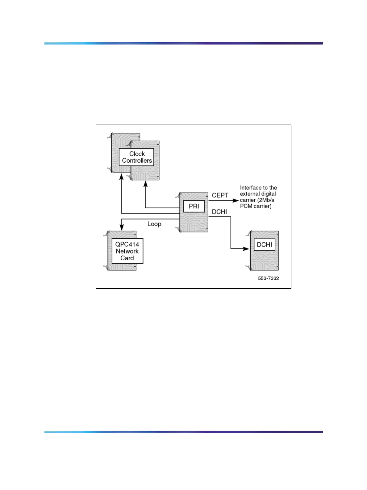
See Figure 1 "PRI hardware (shown without downloadable PRI and DCH
cards)" (page 18) for a representation of the basic PRI system hardware.
Note: Figure 1 shows a basic configuration, not the dual-port NT5D12
DTI/PRI card, nor the associated dual-port NTBK51AA Downloadable
D-Channel daughterboard.
Figure 1 PRI hardware (shown without downloadable PRI and DCH cards)
ISDN Signaling Link (ISL) hardware
The following hardware is required for ISDN Signaling Link (ISL) capability
and applications.
Equipment required for shared mode capability:
• NT6D11(AB/AE/AF) D-Channel (DCH) card (for 2.0 Mb PRI)
•
QPC757 D-channel (DCH) for (1.5 Mb PRI)
•
NT6D80 Multipurpose Serial Data Link (MSDL) card
• NTBK51 Downloadable D-Channel Daughterboard (DDCH), the NT5D97
dual-port DTI2/PRI2 card, or the NT5D12 dual-port 1.5 Mb DTI/PRI card
•
NT8D72 (AB/BA) PRI2 card
•
NT5D97 dual-port DTI2/PRI2 card
•
QPC720 1.5 Mb PRI card
ISDN Primary Rate Interface Installation and Commissioning
Copyright © 2003-2007, Nortel Networks
.
Nortel Communication Server 1000
NN43001-301 02.03 Standard
Release 5.5 7 December 2007
Page 19

ISDN Signaling Link (ISL) hardware 19
•
NT5D12 dual-port 1.5 DTI/PRI card
•
QPC775 Clock Controller or NTRB53
Equipment required for dedicated mode using leased lines:
• NT6D11(AB/AE/AF) D-Channel (DCH) card (for 2.0 Mb PRI)
•
QPC757 D-channel (DCH) for (1.5 Mb PRI)
•
NT6D80 Multipurpose Serial Data Link (MSDL) card
• NTBK51 Downloadable D-Channel Daughterboard (DDCH), used as
an option to the NT6D80 MSDL
•
modem set in synchronous mode
Equipment required for dedicated mode using a dialup modem:
•
NT6D11(AB/AE/AF) D-Channel (DCH) card (for 2.0 Mb PRI)
•
QPC757 D-channel (DCH) for (1.5 Mb PRI)
•
NT6D80 Multipurpose Serial Data Link (MSDL) card
•
NTBK51 Downloadable D-Channel Daughterboard (DDCH), used as
an option to the NT6D80 MSDL
•
modem with autodial capability
Note: This configuration is the least reliable due to lockup problems
inherent in Smart Modems from power spikes and noisy lines. To
increase the reliability on this configuration, use a constant power
source when powering the modems. Also, verify that TIE lines meet data
grade specifications. Nortel takes no responsibility for ISL D-Channel
outages due to modem lockup.
•
500 set line card
•
QPC71 2W TIE, or QPC237 4W TIE E&M
Equipment required for dedicated mode using a DTI/DTI2 trunk:
•
NT6D11(AB/AE/AF) D-Channel (DCH) card (for 2.0 Mb PRI)
•
QPC757 D-channel (DCH) for (1.5 Mb PRI)
•
NT6D80 Multipurpose Serial Data Link (MSDL) card
•
NTBK51 Downloadable D-Channel Daughterboard (DDCH), used as
an option to the NT6D80 MSDL
•
NT5D97 dual-port DTI2/PRI2 card
• QPC472 1.5 Mb DTI card or NT5D12 dual-port 1.5 DTI/PRI card
ISDN Primary Rate Interface Installation and Commissioning
Copyright © 2003-2007, Nortel Networks
.
Nortel Communication Server 1000
NN43001-301 02.03 Standard
Release 5.5 7 December 2007
Page 20

20 ISDN Primary Rate Interface equipment overview
•
QMT8 Asynchronous Data Module (ADM), QMT11 Asynchronous/Synchronous Interface Module (ASIM) or QMT21 High Speed Data Module
(HSDM)
•
Data line card
64 Kbit/s Clear Data Hardware
The QMT21 High Speed Data Module (HSDM) is required in the clear-data
pathway to support the 64Kbit/s clear-data function. One module is required
at each system end of any connection.
D-Channel Handler description
This section provides descriptions of the D-Channel (DCH) cards, the MSDL
card, and the Downloadable D-Channel Daughterboard.
NT6D11 DCH
Power requirements
The power requirements for the NT6D11AB/11AE/AF DCH are:
•
+5 volts at 3 amperes
•
+12 volts at 75 milliamperes
•
-12 volts at 75 milliamperes
DCH/PRI interface
The NT6D11AB/AE/AF DCHs connect to the PRI2 cards by means of a
special RS422 cable, the QCAD328A, which is a special RS422 cable; refer
to "QCAD328" (page 300) of the Cabling chapter for more details.
DCH faceplate
NT6D11AB/AE/AF DCHs have one Light Emitting Diode (LED), to indicate
an active or inactive state, and two external connectors:
•
Port J1 is a standard asynchronous port providing an interface for
non-PRI applications.
Note: This connection will not support an Add-on Data Module (ADM)
terminal.
•
Port J2 is the D-Channel Interface port.
Figure 2 "NT6D11 DCH faceplate layout" (page 21) shows the faceplate
layout.
ISDN Primary Rate Interface Installation and Commissioning
Copyright © 2003-2007, Nortel Networks
.
Nortel Communication Server 1000
NN43001-301 02.03 Standard
Release 5.5 7 December 2007
Page 21
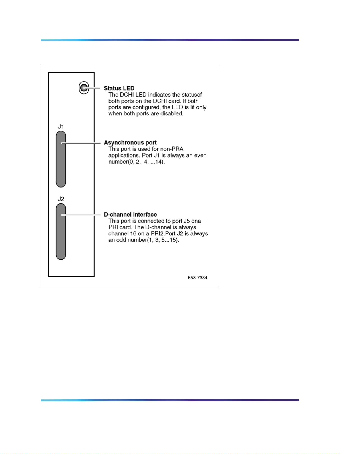
Figure 2 NT6D11 DCH faceplate layout
QPC757 DCH 21
QPC757 DCH
Power requirements
The power requirements for the QPC757 DCH are:
•
+5 volts at 3 amperes
•
+12 volts at 50 milliamperes
•
–12 volts at 50 milliamperes
DCH/PRI interface
The QPC757 DCH connects to the QPC720 PRI via a RS-422 cable. The
following signals are transmitted across the interface:
•
RCV DATA
ISDN Primary Rate Interface Installation and Commissioning
Copyright © 2003-2007, Nortel Networks
.
Nortel Communication Server 1000
NN43001-301 02.03 Standard
Release 5.5 7 December 2007
Page 22

22 ISDN Primary Rate Interface equipment overview
•
RCV CLOCK
•
XMIT CLOCK
•
XMIT READY
•
PRI READY
•
DCH READY
PRI READY and DCH READY are handshake signals.
QPC757 faceplate
The QPC757 DCH, as shown in Figure 3 "QPC757 DCH faceplate layout"
(page 23) has one LED to indicate an active or inactive state and two
external connectors as follows:
•
Port J1 is a standard asynchronous port in LD 48
Note: This connection does not support an Add-on Data Module (ADM)
terminal.
•
Port J2 is the D-Channel Interface port.
Note: A QPC757 vintage C is required if the ISL Revert to Conventional
Signaling feature is configured. The QPC757 vintage D is recommended
for combination ISL/PRI networks using NACD or Network Message
Services and ISL networks using modems.
ISDN Primary Rate Interface Installation and Commissioning
Copyright © 2003-2007, Nortel Networks
.
Nortel Communication Server 1000
NN43001-301 02.03 Standard
Release 5.5 7 December 2007
Page 23
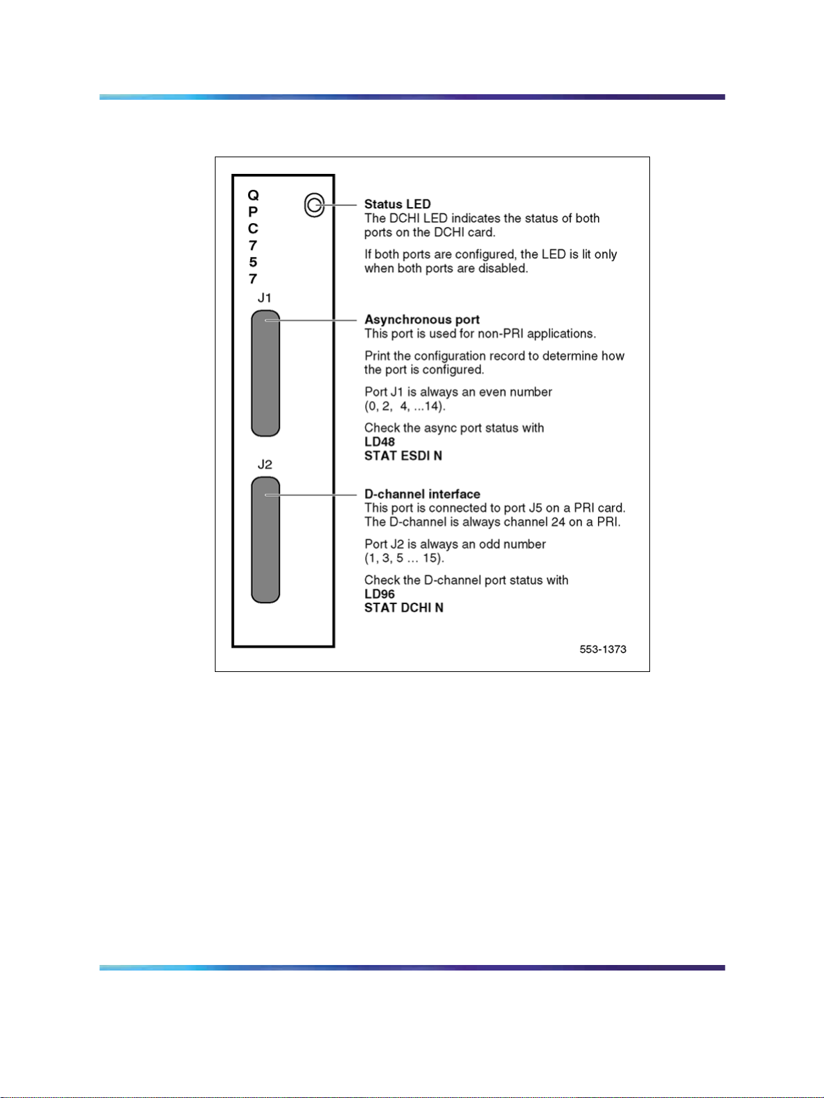
Figure 3 QPC757 DCH faceplate layout
NT6D80 MSDL 23
NT6D80 MSDL
The NT6D80 MSDL card can be used in conjunction with, or independent
of, the QPC757, or NT6D11AB/AE/AF DCH.
Power requirements
The NT6D80 MSDL power requirements are:
Voltage
(VAC)
+5
+12 0.10 1.20 4.15
-12 0.10 1.20 4.15
ISDN Primary Rate Interface Installation and Commissioning
Copyright © 2003-2007, Nortel Networks
.
Current
(Amps)
3.20 16.00 55.36
Nortel Communication Server 1000
NN43001-301 02.03 Standard
Release 5.5 7 December 2007
Power
(Watts)
Heat
(BTUs)
Page 24
24 ISDN Primary Rate Interface equipment overview
MSDL/PRI interface
MSDL can connect to PRI trunks through RS-422 or RS-232 interfaces.
The interfaces are switch configured.
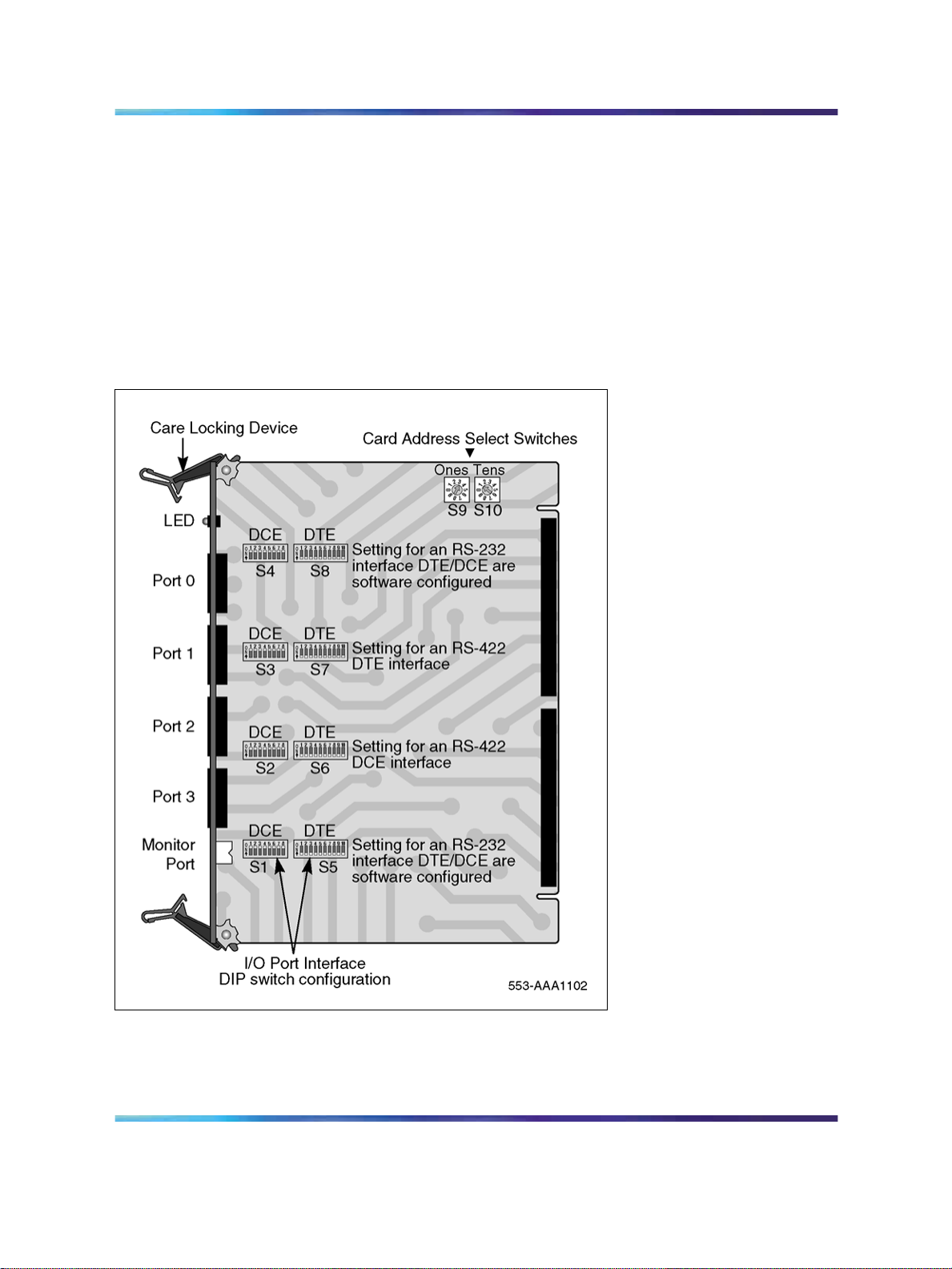
MSDL faceplate
The NT6D80 MSDL has one LED to indicate an active or inactive state and
four external connectors. Each port can be RS-422 or RS-232 connectors,
with either DCE or DTE interfaces. Refer to Figure 4 "NT6D80 MSDL
faceplate layout" (page 24).
Figure 4 NT6D80 MSDL faceplate layout
ISDN Primary Rate Interface Installation and Commissioning
Copyright © 2003-2007, Nortel Networks
.
Nortel Communication Server 1000
NN43001-301 02.03 Standard
Release 5.5 7 December 2007
Page 25

NTBK51 Downloadable D-Channel Daughterboard
The NTBK51 is a two port DownloadableD-Channel Daughterboard (DDCH)
that has been introduced as an option to the NT6D80 MSDL, the NT5D97
dual-port DTI2/PRI2 card, or the NT5D12 dual-port 1.5 Mb DTI/PRI card.
The NTBK51 supports all the features of the existing 4 port MSDL
(NT6D80), and eliminates the need foran external DCH card and associated
cables for MSDL applications. The NTBK51 can support a maximum of 32
(16*2) MSDL type D-Channels per system, unlike the MSDL which can
support a maximum of 64.
Note 1: Only one version, the NTBK51AA, can be used with the
NT5D97, or the NT5D12. The NTBK51BA version has only 30+30 pin
connectors (instead of 40+30 pins in the AA version). The missing 10
pins in the BA version prohibits the use of port 0 on the NT5D97, or
NT5D12 card.
Note 2: The software allocation for NTBK51AA DDCH is similar to
the MSDL. It is both physical and logical, and supports D-Channel
functionality only.
NT8D72 PRI2 25
Note 3: Port 0 has to be an even loop on the DDP2, and Port 1 has to
be an odd loop. Port 2 and Port 3 should not be configured.
The connection between the dual-port cards and the DDCH daughterboard
is made using two headers: one 30 pin and one 40 pin connector.
Standard PRI cards
This section provides a description of the standard ISDN PRI cards, namely
the NT8D72 (AB/BA) PRI2 card, and the QPC720 1.5 Mb PRI card.
NT8D72 PRI2
Power requirements
The NT8D72AB and NT8D72BA PRI use power and ground connections
from the backplane. Power requirements are:
+5 volts at 4 amperes
+12 volts at 50 milliamperes
-12 volts at 50 milliamperes
NT8D72 faceplate
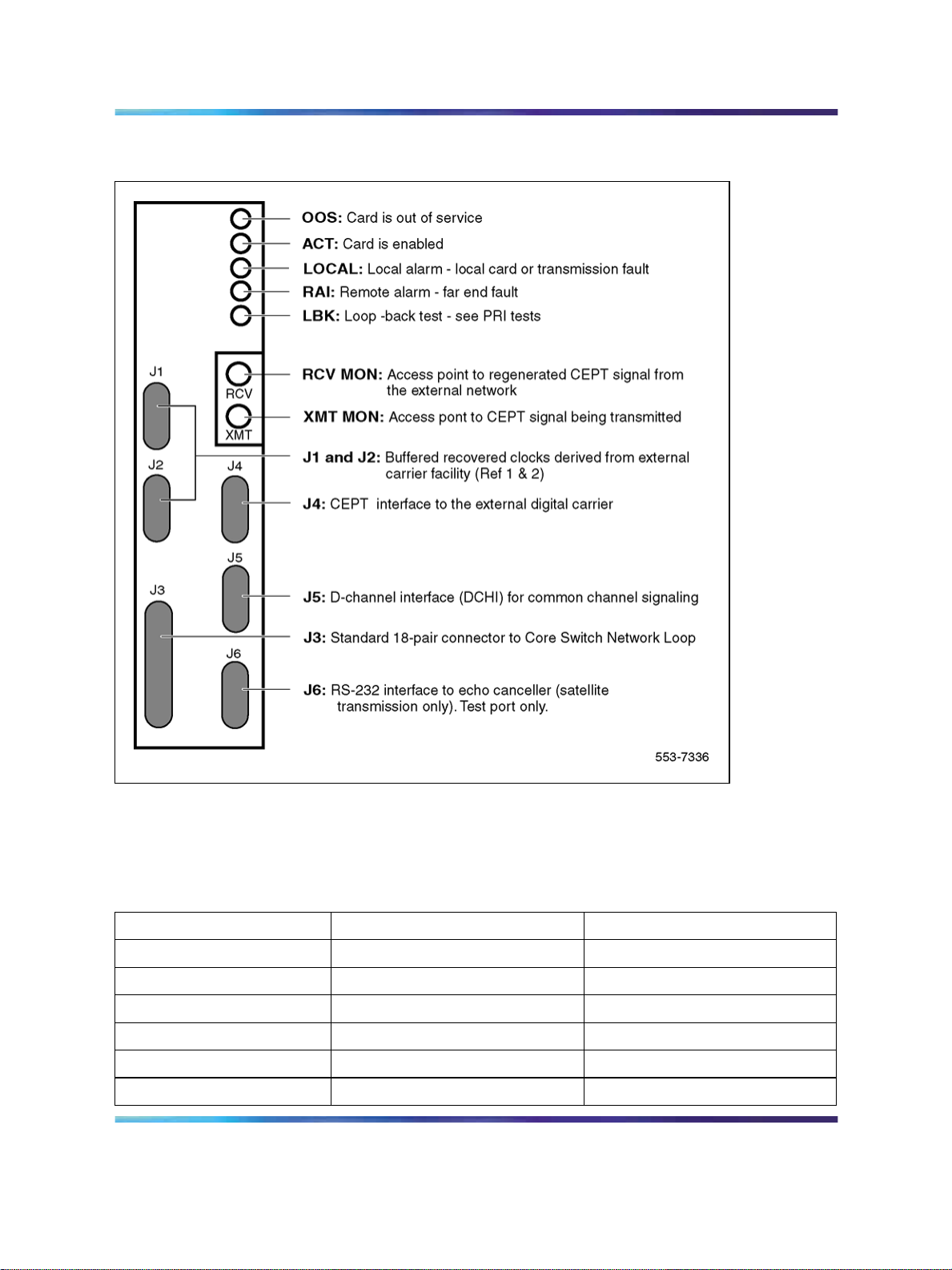
The NT8D72 contains five LEDs and six external connectors. Figure 5
"NT8D72 PRI faceplate layout" (page 26) shows the faceplate layout.
ISDN Primary Rate Interface Installation and Commissioning
Copyright © 2003-2007, Nortel Networks
.
Nortel Communication Server 1000
NN43001-301 02.03 Standard
Release 5.5 7 December 2007
Page 26
26 ISDN Primary Rate Interface equipment overview
Figure 5 NT8D72 PRI faceplate layout
Table 2 "NT8D72 PRI External connectors" (page 26) gives information
about the external connectors located on the NT8D72 PRI2 faceplate.
Table 2 NT8D72 PRI External connectors
Faceplate Destination Type Description
J1 9-pin female, D-connector Reference Clock 0 interface
J2 9-pin female, D-connector Reference Clock 1 interface
J3 36-pin connector Loop interface
J4 15-pin male, D-connector External digital trunk
J5 15-pin male, D-connector D-Channel interface
J6 15-pin female, D-connector Echo Canceller/RS-232 interface
ISDN Primary Rate Interface Installation and Commissioning
Copyright © 2003-2007, Nortel Networks
.
Nortel Communication Server 1000
NN43001-301 02.03 Standard
Release 5.5 7 December 2007
Page 27
NT8D72 PRI2 27
Faceplate Destination Type Description
RCV MON Miniature bantam jack Monitor DSI from network
XMT MON Miniature bantam jack Monitor DSI from PRI
Cable requirements
Table 3 "NT8D72AB and NT8D72BA PRI: Cables and cable lengths" (page
27) lists the types of cable used and the lengths required for internal and
external NT8D72 PRI2 connections.
Note: No additional cabling is required fornB+D configurations. Multiple
PRIs and the D-Channel are associated at the PRI prompt in LD 17.
Table 3 NT8D72AB and NT8D72BA PRI: Cables and cable lengths
Maximum length
Cable Type From To
(meters)
NT8D79AA PRI card Clock controller (CC-0)
NT8D79AA PRI card Clock controller (CC-1)
QCAD328A PRI card DCH card
QCAD328B PRI card DCH card
QCAD328C PRI card DCH card
QCAD328D PRI card DCH card
NTND26AA PRI card MSDL
NTND26AB PRI card MSDL
NTND26AC PRI card MSDL
NTND26AD PRI card MSDL
NT8D85AB PRI card Network Network Card
RS-232 PRI card Echo canceller
NT8D7207 PRI card I/O panel
NT8D7205 I/O panel
crossconnect
Carrier interface
The NT8D72 PRI2 provides an interface to the 2Mb external digital
line either directly or through an office repeater, echo canceller or line
terminating unit (LTU).
2.13
2.13
1.8
5.5
10.67
15.24
1.8
5.5
10.67
15.24
15.24
15.24
3.05
15.24
ISDN Primary Rate Interface Installation and Commissioning
Copyright © 2003-2007, Nortel Networks
.
Nortel Communication Server 1000
NN43001-301 02.03 Standard
Release 5.5 7 December 2007
Page 28

28 ISDN Primary Rate Interface equipment overview
Echo canceller interface
Echo cancellers are required only on satellite transmission circuits. The
echo canceller detects the length of the loop, and then cancels out reflected
transmission. (Callers will not hear echoes of their own voices reflecting
back to them from the far end of the call.)
The echo canceller’s control protocol must conform with that of the Tellabs
Model 251. Both the echo canceller and the PRI circuit card act as Data
Terminal Equipment (DTE).
QMT21 High Speed Data Module
The QMT21 High Speed Data Module supports the 64K Clear Data feature.
(It allows data terminating equipment (DTE) to send and receive 64-Kb/s
clear data.) The QMT21B is required for Large System to Large System
configurations.
QPC720 PRI for 1.5/2.0 Mb gateway
Systems which are being used as a 1.5/2.0 Mb Gateway, one or more
QPC720 (1.5 Mb) Primary Rate Interface circuit cards will also be needed.
Note: Older vintages of the QPC720 PRI cannot be used for Gateway
applications. The 1.5/2.0 Mb Gateway feature requires the use of a
QPC720 circuit card with firmware updated to provide modified PAD
values.
Clock operation for the NT8D72
There are two types of clock operation—tracking mode and free-run mode.
Tracking mode
In tracking mode, the PRI loop supplies an external clock reference to a
clock controller. Two PRI loops can operate in tracking mode, with one
defined as the primary reference source for clock synchronization, the other
defined as the secondary reference source. The secondary reference acts
as a back-up to the primary reference.
As shown in Figure 6 "Clock controller primary and secondary tracking"
(page 29), a system with dual CPUs can have two clock controllers (CC-0
and CC-1). One clock controller acts as a back-up to the other. The clock
controllers should be completely locked to the reference clock.
ISDN Primary Rate Interface Installation and Commissioning
Copyright © 2003-2007, Nortel Networks
.
Nortel Communication Server 1000
NN43001-301 02.03 Standard
Release 5.5 7 December 2007
Page 29
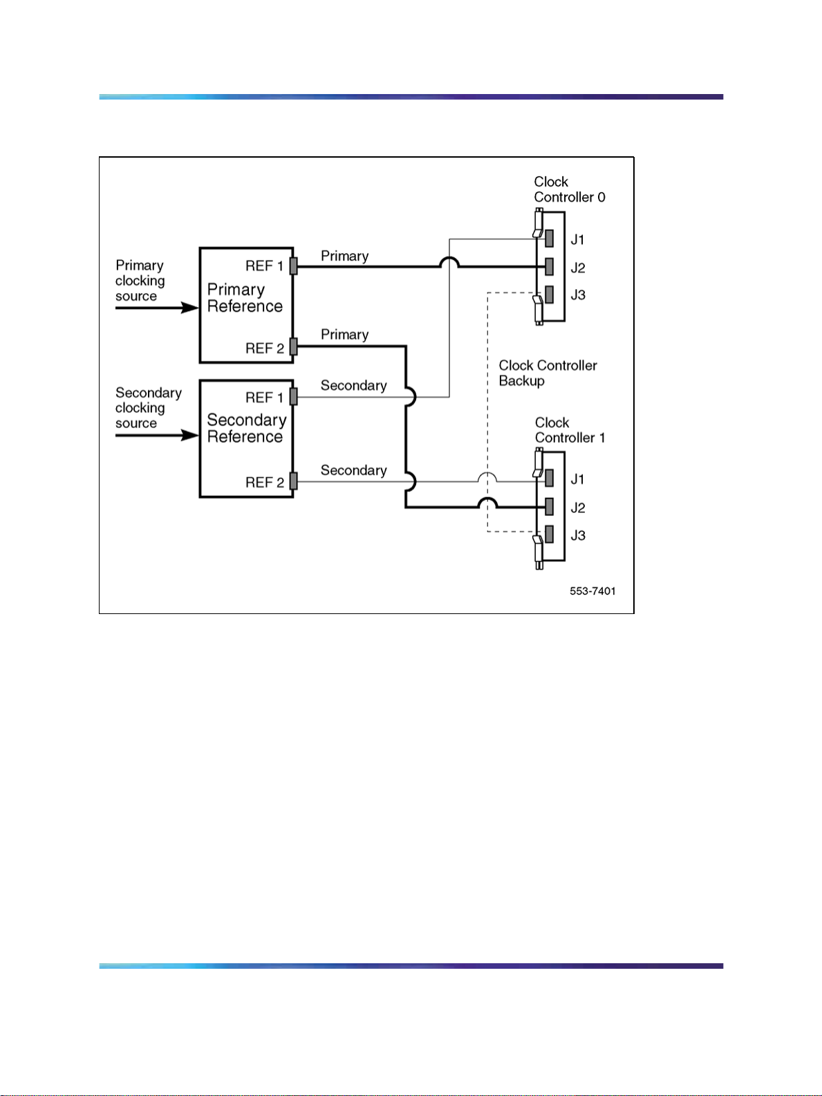
Figure 6 Clock controller primary and secondary tracking
NT8D72 PRI2 29
Free run (non-tracking) mode
The clock synchronization of the system can operate in free-run mode if:
•
no loop is defined as the primary or secondary clock reference,
•
the primary and secondary references are disabled, or
•
the primary and secondary references are in local alarm
Reference clock errors
The system software checks at intervals of 1 to 15 minutes to see if a clock
controller or reference-clock error has occurred. (The interval of this check
can be configured in LD 73.)
In tracking mode, at any one time, there is one active clock controller which
is tracking on one reference clock. If a clock-controller error is detected, the
system switches to the back-up clock controller, without affecting which
reference clock is being tracked.
ISDN Primary Rate Interface Installation and Commissioning
Copyright © 2003-2007, Nortel Networks
.
Nortel Communication Server 1000
NN43001-301 02.03 Standard
Release 5.5 7 December 2007
Page 30

30 ISDN Primary Rate Interface equipment overview
A reference-clock error occurs when there is a problem with the clock driver
or with the reference clock at the far end. If the clock controller detects a
reference-clock error, the reference clocks are switched.
Automatic clock recovery
A command for automatic clock recovery can be selected in LD 60 with
the command EREF.
A PRI loop is disabled when it enters a local-alarm condition. If the local
alarm is cleared, the loop is enabled automatically. When the loop is
enabled, clock tracking is restored in the following conditions:
1. If the loop is assigned as the primary reference clock but the clock
controller is tracking on the secondary reference or in free-run mode, it
is restored to tracking on primary.
2. If the loop is assigned as the secondary reference clock but the clock
controller is in free-run mode, it is restored to tracking on secondary.
If the clock check indicates the switch is in free-run mode:
1. Tracking is restored to the primary reference clock if defined.
QPC720 PRI
Power requirements
2. If the primary reference is disabled or in local alarm, tracking is restored
to the secondary reference clock if defined.
Note: If the switch is put into free-run mode by the craftsperson, it will
resume tracking on a reference clock unless the clock-switching option
has been disabled (LD 60, command MREF), or the reference clock has
been "undefined" in the database.
Automatic clock switching
If the EREF command is selected in LD 60, tracking on the primary or
secondary reference clock is automatically switched in the following manner:
1. If software is unable to track on the assigned primary reference clock, it
switches to the secondary reference clock and sends appropriate DTC
maintenance messages.
2. If software is unable to track on the assigned secondary reference clock,
it switches to free run.
The QPC720 PRI card is required for PRI operation in all machine types.
The QPC720 PRI uses power and ground from the backplane. This card
does not require an intelligent bus. Power requirements are:
•
+5 volts at 6 amperes
ISDN Primary Rate Interface Installation and Commissioning
Copyright © 2003-2007, Nortel Networks
.
Nortel Communication Server 1000
NN43001-301 02.03 Standard
Release 5.5 7 December 2007
Page 31

•
+12 volts at 50 milliamperes
•
-12 volts at 50 milliamperes
QPC720 faceplate
QPC720 PRI contains five LEDs and six external connectors. Figure 7
"QPC720 PRI faceplate layout" (page 31) shows the QPC720 PRI faceplate
layout. Table 4 "QPC720 PRI external connectors" (page 31) gives
information about the external connectors located on the QPC720 PRI
faceplate.
Figure 7 QPC720 PRI faceplate layout
QPC720 PRI 31
Table 4 QPC720 PRI external connectors
Faceplate destination Type
J1 9-pin female, D-connector
ISDN Primary Rate Interface Installation and Commissioning
Copyright © 2003-2007, Nortel Networks
.
Nortel Communication Server 1000
NN43001-301 02.03 Standard
Release 5.5 7 December 2007
Page 32

32 ISDN Primary Rate Interface equipment overview
Faceplate destination Type
J2 9-pin female, D-connector
J3 36-pin connector
J4 15-pin male, D-connector
J5 15-pin male, D-connector
J6 15-pin female, D-connector
RCV MON Miniature bantam jack
XMT MON Miniature bantam jack
QPC720 Cable requirements
Table 5 "QPC720 PRI cables and cable lengths" (page 33) lists the types of
cable used and the lengths required for external QPC720 PRI connections.
Note: No additional cabling is required fornB+D configurations. Multiple
PRIs and the D-channel are associated through software in LD 17,
prompt PRI.
Carrier interface
The QPC720 PRI provides an interface to the DS-1 Channel either directly,
through an office repeater, or through an Echo Canceller.
The T1 Channel Service Units listed below are compatible with the QPC720
PRI card and the 64K Clear Data feature as well as with PRI connection
parameters such as the Superframe format, the Extended superframe
format, and the B7 and B8ZS Alternate Mark Inversion (AMI) line coding.
•
Digital Link 551A
•
Digital Link 551C
•
Digital Link 551E
• Tellabs Model 441
•
Verilink Model 551V ST
In the U.S.A., FCC Part 68 regulations require Network Channel Terminating
Equipment (for example, the NT QRY551 Channel Service Unit) installed
at of the point of connection between a system and a registered common
carrier trunk.
Echo Canceller interface
Echo Cancellers are required only with satellite transmission. The Echo
Canceller detects the length of the loop, then cancels the reflected
transmission (callers do not hear their own voices echoed).
ISDN Primary Rate Interface Installation and Commissioning
Copyright © 2003-2007, Nortel Networks
.
Nortel Communication Server 1000
NN43001-301 02.03 Standard
Release 5.5 7 December 2007
Page 33

The QPC720 PRI provides both a T1 line interface and a control interface to
link to a signal format compatible with EIA standard RS-232-C. Both the PRI
and the Echo Canceller act as Data Terminal Equipment (DTE). The Echo
Canceller’s control protocol must conform to that of the Tellabs Model 251.
64 T-link version 2 protocol
The QPC720 card supports the 64 T-link version 2 protocol. The QPC720
together with theQMT21 High Speed Data Module supports the 64K Clear
Data feature. The QPC720 card provides a trunk that ties two switches
together. This trunk allows 64K eClear Data to pass from the system to an
outside network. The QMT21 module allows Data Terminal Equipment
(DTE) to send and receive 64K Clear Data. See
General Guide (553-2901-100) for more information about the 64K Clear
Data feature.
Table 5 QPC720 PRI cables and cable lengths
Cable type From To
QCAD130 QPC720 QPC471/QPC775 (CC-0)
QCAD130 QPC720 QPC471/QPC775 (CC-1)
QCAD328A QPC720 QPC757 DCHI
QCAD328B QPC720 QPC757 DCHI
QPC720 PRI 33
Meridian Link ISDN/AP
Maximum
length (feet)
7
7
6 1.8
18
Maximum
length
(meters)
2.13
2.13
5.5
QCAD328C QPC720 QPC757 DCHI
QCAD328D QPC720 QPC757 DCHI
QCAD124 QPC720 QPC414 Network
QCAD128 QPC720 Bulkhead I/O panel
RS-232 QPC720 Echo Canceller
NTND26AA QPC720 NT6D80 MSDL
NTND26AB QPC720 NT6D80 MSDL
NTND26AC QPC720 NT6D80 MSDL
NTND26AD QPC720 NT6D80 MSDL
NTND98 QPC720 Input/output panel
22AWG ABAM Echo Canceller DSX-1
Note: The QPC775 Clock Controller is not available in the U.S.A. There
can be no mixing of QPC775 and QPC471 in one system.
ISDN Primary Rate Interface Installation and Commissioning
Copyright © 2003-2007, Nortel Networks
.
Nortel Communication Server 1000
NN43001-301 02.03 Standard
Release 5.5 7 December 2007
35 10.67
50 15.24
50 15.24
25 7.62
50 15.24
6 1.8
18
35 10.67
50 15.24
6 1.8
655 199.64
5.5
Page 34

34 ISDN Primary Rate Interface equipment overview
Disk drive hardware
The following hardware is required for Large System upgrades:
•
3.5-inch disk drive unit
•
disk drive controller for above
•
cable for above
NT5D97 Dual-port DTI2/PRI2 card
The NT5D97 is a dual-port 2.0 Mb DTI2/PRI2 card (the DDP2 firmware
functions in DTI2 or PRI2 mode, depending on DIP switch settings) that
integrates the functionality of two NT8D72BA PRI2 cards, and one QPC414
ENET card into a single CE card. The NT5D97 occupies a single slot in
the Network shelf and provides two DTI2/PRI2 network connections: an
interface to an external D-Channel Handler (the NT6D11AF) or the NT6D80
Multipurpose Serial Data Link card, and an optional plug-on NTBK51AA
Downloadable D-Channel daughterboard (DDCH) with two DCH interface
ports.
The NT5D97 DDP2 card can be mixed in the same machine with PRI2
NT8D72BA cards.
The NT5D97 DDP2 card hardware design uses a B57 ASIC E1/T1 framer.
The carrier specifications comply with the ANSI TI.403 specification. The
NT5D97 provides an interface to the 2.048 Mbps external digital line
either directly or through an office repeater, Network Channel Terminating
Equipment (NCTE), or Line Terminating Unit (LTU).
DANGER
DANGER OF ELECTRIC SHOCK
The NT5D97 DDP2 card is not designed to be connected
directly to the Public Switched Network, or other exposed plant
networks. Such a connection should only be done using an
isolating-type networking terminating device that provides voltage
surge protection, such as a Line Terminating Unit (LTU), Network
Channel Terminating Equipment (NCTE), or Network Termination
1 (NT1), as certified by your local, regional, or national safety
agency and telecommunications authority.
External D-Channel Interface DCH or MSDL
The connection between the DDP2 card and the external DCH or MSDL is
through a 26 pin female D type connector. The data signals conform to the
electrical characteristics of the EIA standard RS-422.
ISDN Primary Rate Interface Installation and Commissioning
Copyright © 2003-2007, Nortel Networks
.
Nortel Communication Server 1000
NN43001-301 02.03 Standard
Release 5.5 7 December 2007
Page 35

NT5D97 Dual-port DTI2/PRI2 card 35
Two control signals are used to communicate the D-channel link status
to the DCH or MSDL. These are:
•
Receiver Ready (RR), originating at the DDP2 card, to indicate to the
DCH or MSDL that the D-channel link is operational.
•
Transmitter Ready (TR), originating at the DCH or MSDL, to indicate to
the DDP2 card that the DCH are ready to use the D-channel link.
Table 6 "DCH/MSDL Receiver Ready control signals" (page 35) indicates
how the RR control signal operates with regard to the DDP2 status.
Table 6 DCH/MSDL Receiver Ready control signals
RR State Condition
ON D-Channel data rate selected at 64 Kbps
and
PRI2 loop is enabled
OFF All other conditions
NT5D97 faceplate
Figure 8 "NT5D97 faceplate" (page 36) illustrates the faceplate layout for
the NT5D97 DDP card. The faceplate contains an enable/disable switch;
a DDCH status LED; 6 x 2 trunk port status LEDs; and six external
connectors. Table 7 "External connectors and LEDs" (page 36) shows the
name of each connector, its designation with respect to the faceplate and
the name and description of the card it is connected to. Also shown are the
names of the LEDs.
and
PRI2 link is not in OOS or Local Alarm mode state
and
PRI2 link is not transmitting a Remote Alarm pattern
and
PRI2 link is not receiving a Remote Alarm Indication from
a remote facility
ISDN Primary Rate Interface Installation and Commissioning
Copyright © 2003-2007, Nortel Networks
.
Nortel Communication Server 1000
NN43001-301 02.03 Standard
Release 5.5 7 December 2007
Page 36

36 ISDN Primary Rate Interface equipment overview
Figure 8 NT5D97 faceplate
Table 7 External connectors and LEDs
Faceplate
Function
Designator Type Description
Switch ENB/DIS Plastic, ESD protected Card Enable/disable
switch
ISDN Primary Rate Interface Installation and Commissioning
Copyright © 2003-2007, Nortel Networks
.
Nortel Communication Server 1000
NN43001-301 02.03 Standard
Release 5.5 7 December 2007
Page 37

Function
NT5D97 Dual-port DTI2/PRI2 card 37
Faceplate
Designator Type Description
Connectors
LEDs
Unit 0 Clock 0 RJ11 Connector Connects reference
clock 0 to Clock
Controller card 0
Unit 0 Clock 1 RJ11 Connector Connects reference
clock 0 to Clock
Controller card 1
Unit 1 Clock 0 RJ11 Connector Connects reference
clock 1 to Clock
Controller card 0
Unit 1 Clock 1 RJ11 Connector Connects reference
clock 1 to Clock
Controller card 1
J5 TRK 9 Pin
Female D Connector
J6 DCH 26 Pin
Female D Connector
ENET 2 Red LEDs ENET 0 or ENET 1 is
DIS 2 Red LEDs Trunk 0 or Trunk 1 is
OOS 2 Yellow LEDs Trunk is out of service
Two external E1 Trunk
0 and Trunk 1
Connects to external
DCH or MSDL
disabled
disabled
NEA 2 Yellow LEDs Local (Near End) Alarm
FEA 2 Yellow LEDs Far End Alarm
LBK 2 Yellow LEDs Loop Back test being
performed on Trunk 0
or Trunk 1
DCH Bicolor Red/Green LED NTBK51AA status
The following is a brief description of each element on the faceplate.
Enable/Disable Switch
This switch is used to disable the card prior to insertion or removal from
the network shelf. While this switch is in disable position, the card will not
respond to the system CPU.
ENET LEDs
Two red LEDs indicate if the "ENET0" and "ENET1" portions of the card are
disabled. These LEDs are lit in the following cases:
•
When the enable/disable switch is in disabled state (lit by hardware).
•
After power-up, before the card is enabled.
ISDN Primary Rate Interface Installation and Commissioning
Copyright © 2003-2007, Nortel Networks
.
Nortel Communication Server 1000
NN43001-301 02.03 Standard
Release 5.5 7 December 2007
Page 38

38 ISDN Primary Rate Interface equipment overview
•
When the ENET port on the card is disabled by software.
Trunk Disable (DIS) LEDs
Two red LEDs indicate if the "trunk port 0" or "trunk port 1" portions of the
card are disabled. These LEDs are lit in the following cases:
•
upon reception of the "disable loop" message from the software
•
after power-up
OOS LEDs
Two yellow LEDs indicate if the "trunk port 0" and "trunk port 1" portions of
the card are out-of-service.
NEA LEDs
Two yellow LEDs indicate if the near end detects absence of incoming signal
or loss of synchronization in "trunk port 0" or "trunk port 1" respectively.
The Near End Alarm causes a Far End Alarm signal to be transmitted to
the far end.
FEA LEDs
Two yellow LEDs indicate if a Far End Alarm has been reported by the far
end (usually in response to a Near End Alarm condition at the far end)
on "trunk port 0" or "trunk port 1".
LBK LEDs
Two yellow LEDs indicate if a remote loopback test is being performed on
trunk port 0 or trunk port 1. The loopback indication is active when the
digital trunk is in remote loopback mode. Normal call processing is inhibited
during the remote loopback test.
DCH LED
When the dual colored LED is red, it indicates the onboard DDCH is present
but disabled. When the dual colored LED is green, it indicates the onboard
DDCH is present and enabled. If a DDCH is not configured on the DDP2
card, this lamp is not lit.
Unit 0 Clk Connectors
Two RJ11 connectors for connecting:
•
Digital trunk unit 0 recovered clock to primary or secondary reference
source on clock controller card 0.
• Digital trunk unit 0 recovered clock to primary or secondary reference
source on clock controller card 1.
ISDN Primary Rate Interface Installation and Commissioning
Copyright © 2003-2007, Nortel Networks
.
Nortel Communication Server 1000
NN43001-301 02.03 Standard
Release 5.5 7 December 2007
Page 39

Unit 1 Clk Connectors
Two RJ11 connectors for connecting:
•
Digital trunk unit 1 recovered clock to primary or secondary reference
source on clock controller card 0.
•
Digital trunk unit 1 recovered clock to primary or secondary reference
source on clock controller card 1.
Connector J5 (TRK)
A 9 pin D-Type connector used to connect:
•
Digital trunk unit 0 receive and transmit Tip / Ring pairs
•
Digital trunk unit 1 receive and transmit Tip / Ring pairs
Connector J6 (DCH)
A 26-pin D-type connector is used to connect the DDP2 card to the external
MSDL or D-channel handler.
System capacity and performance
Physical capacity
Each NT5D97 DDP2 card occupies one slot on the network shelf. Each card
supports two digital trunk circuits and two network loops. The total number
of DDP2 cards per system is limited by the number of network loops,
physical capacity of the shelf, number of DTI2/PRI2 interfaces allowed by
the software and the range of DCH addresses.
NT5D97 Dual-port DTI2/PRI2 card 39
D-Channel capacity
The software configuration for the NTBK51AA DDCH is similar to the MSDL
and only supports D-channel functionality.
The system has a total capacity of 16 addresses (Device Addresses or
DNUM) that can be reserved for DCH card, MSDL card or DDCH card. One
exception is DNUM 0 which is commonly assigned to the TTY terminal.
No two different D-Channel providers can share the same DNUM. Hence,
the combined maximum number of DCH, MSDL and DDCH cards in the
system is 16.
The DCH has one D-Channel unit, the DDCH has two D-Channel units,
and the MSDL has a maximum of four units. Therefore, the total number
of D-Channel is derived by the following formula:
Total_Num_DCH-Units = Num_DCHx1 + Num_DDCHx2 + Num_MSDLx4
Therefore, Total_Num_DCH-Units in any given system is between 0-63.
ISDN Primary Rate Interface Installation and Commissioning
Copyright © 2003-2007, Nortel Networks
.
Nortel Communication Server 1000
NN43001-301 02.03 Standard
Release 5.5 7 December 2007
Page 40

40 ISDN Primary Rate Interface equipment overview
CPU capacity
Using a NT5D97 DDP2 card instead of DTI2/PRI2 cards does not increase
the load on the system CPU. The DDP2 replaces an ENET card and two
DTI2/PRI2 cards. Emulating the ENET card and the overall CPU capacity is
not impacted by using a DDP2 card instead of a DTI2/PRI2 card.
Power requirements
Table 8 "NT5D97 DDP2 power requirements" (page 40) lists the power
requirements for the NT5D97 DDP2 card.
Table 8 NT5D97 DDP2 power requirements
Voltage
+5V Backplane 3A 3.8A
+12V Backplane 25mA 75mA
-12V Backplane 25mA 75mA
Total Power (Maximum) 15.6W 20.8W
Testability and diagnostics
The DDP2 card supports testing and maintenance functions through the
following procedures:
•
Self test upon power up or reset
•
Signalling test performed in the LD 30
•
Loopback tests, self tests, and continuity tests performed by LD 60
and LD 45
•
The D-Channel (DCH, MSDL, DDCH) maintenance is supported by
LD 96.
Source Current
DDP2
(without
NTBK51AA)
DDP2
(with
NTBK51AA)
Note: The MSDL selftest is not applicable to the NTBK51AA D-Channel
daughterboard.
Cable requirements
This section lists the types of cable used and the lengths required for
internal and external NT5D97 DDP2 connections.
Note: No additional cabling is required fornB+D configurations. Multiple
DDP2 cards and the D-channel are associated through software in
LD 17.
ISDN Primary Rate Interface Installation and Commissioning
Copyright © 2003-2007, Nortel Networks
.
Nortel Communication Server 1000
NN43001-301 02.03 Standard
Release 5.5 7 December 2007
Page 41

NT5D97 Dual-port DTI2/PRI2 card 41
DDP2 cable assemblies include:
•
E1 carrier cables
— NTCK45AA (A0407956)
— NT8D7217 (A0617192)
— NTCK78AA (A0618294)
— NTCK79AA (A0618296)
•
DDP2 to QPC471/QPC775 Clock Controller Cables
— NTCG03AA
— NTCG03AB
— NTCG03AC
— NTCG03AD
•
DDP2 to DCH cables
— NTCK46AA
— NTCK46AB
— NTCK46AC
— NTCK46AD
•
DDP2 to MSDL cables
— NTCK80AA
— NTCK80AB
— NTCK80AC
— NTCK80AD
A description of each type of DDP2 cable follows.
E1 carrier cables
NTCK45AA (A0407956) The NTCK45AA (8 ft.) is an 120W cable for
systems equipped with an I/O filter panel, connecting the TRK port (P1,
D-type 9 pin male) on the DDP2 faceplate to the I/O filter (P2, P3 D-type 9
pin males).
ISDN Primary Rate Interface Installation and Commissioning
Copyright © 2003-2007, Nortel Networks
.
Nortel Communication Server 1000
NN43001-301 02.03 Standard
Release 5.5 7 December 2007
Page 42

42 ISDN Primary Rate Interface equipment overview
Figure 9 NTCK45AA
Table 9 "NTCK45AA cable pins" (page 42) lists the pin attributes for the
NTCK45AA cable.
Table 9 NTCK45AA cable pins
Cable Name Description Color
0
0
0
0
0
0
0
0
1
1
1
1
1
1
1
1
T-PRI0TX Trunk 0 Transmit Tip Black P1-1 P2-6
R-PRI0TX Trunk 0 Transmit Ring Red P2-2 P2-7
T-PRI0RX Trunk 0 Receive Tip Black P1-3 P2-2
R-PRI0RX Trunk 0 Receive Ring White P1-4 P2-3
GND Shield Wire Bare N/C Case P2
GND Shield Wire Bare N/C Case P2
Standard Wire (3") Bare Case P2 P2-5
Standard Wire (3") Bare Case P2 P2-9
T-PRI1TX Trunk 1 Transmit Tip Black P1-5 P3-6
R-PRI1TX Trunk 1 Transmit Ring Red P1-6 P3-7
T-PRI1RX Trunk 1 Receive Tip Black P1-7 P3-2
R-PRI1RX Trunk 1 Receive Ring White P1-8 P3-3
GND Shield Wire Bare N/C Case P3
GND Shield Wire Bare N/C Case P3
Standard Wire (3") Bare Case P3 P3-5
Standard Wire (3") Bare Case P3 P3-9
DDP2
pins
I/O Panel
pins
NT8D7217 (A0617192) The NT8D7217 (50 ft.) is a 120W cable for
systems equipped with an I/O filter panel, connecting the 9 pin I/O filter
connector to the 9 pin NCTE connector.
ISDN Primary Rate Interface Installation and Commissioning
Copyright © 2003-2007, Nortel Networks
.
Nortel Communication Server 1000
NN43001-301 02.03 Standard
Release 5.5 7 December 2007
Page 43

Figure 10 NT8D7217
Table 10 "NT8D7217 cable pins" (page 43) which follows lists the pin
attributes for the NT8D7217 cable.
Table 10 NT8D7217 cable pins
NT5D97 Dual-port DTI2/PRI2 card 43
Cable Name Description Color
0
0
0
0
0
0
1
1
1
1
1
1
T-PRI0TX Trunk 0 Transmit Tip Black P1-6 P2-6
R-PRI0TX Trunk 0 Transmit Ring White P1-7 P2-7
T-PRI0RX Trunk 0 Receive Tip Black P1-2 P2-2
R-PRI0RX Trunk 0 Receive Ring Red P1-3 P2-3
GND Shield Wire Bare P1-5 N/C
GND Shield Wire Bare P1-9 N/C
T-PRI1TX Trunk 1 Transmit Tip Black P1-6 P2-6
R-PRI1TX Trunk 1 Transmit Ring White P1-7 P2-7
T-PRI1RX Trunk 1 Receive Tip Black P1-2 P2-2
R-PRI1RX Trunk 1 Receive Ring Red P1-3 P2-3
GND Shield Wire Bare P1-5 N/C
GND Shield Wire Bare P1-9 N/C
NTCK78AA (A0618294) The NTCK78AA (50 ft.) is a 120W cable for
connecting the TRK port on the DDP2 faceplate (P1, D-type 9 pin male)
to the Main Distribution Frame (MDF) (P2, P3 D-type 15-pin males). The
NTCK78AA is used for systems not equipped with an I/O filter panel.
DDP2
pins
I/O Panel
pins
ISDN Primary Rate Interface Installation and Commissioning
Copyright © 2003-2007, Nortel Networks
.
Nortel Communication Server 1000
NN43001-301 02.03 Standard
Release 5.5 7 December 2007
Page 44

44 ISDN Primary Rate Interface equipment overview
Figure 11 NTCK78AA
Table 11 "NTCK78AA cable pins" (page 44) lists the pin attributes for the
NTCK78AA cable.
Table 11 NTCK78AA cable pins
Cable Name Description Color
0
0
0
0
0
0
1
1
1
1
1
1
T-PRI0TX Trunk 0 Transmit Tip Black P1-1 P2-1
R-PRI0TX Trunk 0 Transmit Ring Red P1-2 P2-9
T-PRI0RX Trunk 0 Receive Tip Black P1-3 P2-3
R-PRI0RX Trunk 0 Receive Ring White P1-4 P2-11
GND Shield Wire Bare P1 Case P2-2
GND Shield Wire Bare P1 Case P2-4
T-PRI1TX Trunk 1 Transmit Tip Black P1-5 P3-1
R-PRI1TX Trunk 1 Transmit Ring Red P1-6 P3-9
T-PRI1RX Trunk 1 Receive Tip Black P1-7 P3-3
R-PRI1RX Trunk 1 Receive Ring White P1-8 P3-11
GND Shield Wire Bare P1 Case P3-2
GND Shield Wire Bare P1 Case P3-4
NTCK79AA (A0618296) The NTCK79AA (40 ft) is a 75W coaxial cable for
connecting the TRK port on the DDP2 faceplate (P1, D-type 9 pin male) to
the Line Terminating Unit (LTU) (P2, P3, P4, P5 BNC males).
DDP2
pins
NCTE
pins
ISDN Primary Rate Interface Installation and Commissioning
Copyright © 2003-2007, Nortel Networks
.
Nortel Communication Server 1000
NN43001-301 02.03 Standard
Release 5.5 7 December 2007
Page 45

Figure 12 NTCK79AA
Table 12 "NTCK79AA cable pins" (page 45) lists the pin attributes for the
NTCK79AA cable.
Table 12 NTCK79AA cable pins
NT5D97 Dual-port DTI2/PRI2 card 45
Cable Name Description Color
0
0
0
0
1
1
1
1
1
1
T-PRI0TX Trunk 0 Transmit Tip Red P1-1 P2 inner
R-PRI0TX Trunk 0 Transmit Ring Red P1-2 P2 shield
T-PRI0RX Trunk 0 Receive Tip Green P1-3 P3 inner
R-PRI0RX Trunk 0 Receive Ring Green P1-4 P3 shield
T-PRI1TX Trunk 1 Transmit Tip Red P1-5 P4 inner
R-PRI1TX Trunk 1 Transmit Ring Red P1-6 P4 shield
T-PRI1RX Trunk 1 Transmit Tip Green P1-7 P5 inner
R-PRI1RX Trunk 1 Receive Ring Green P1-8 P5 shield
Outer metalized PVC shield Bare N/C P1 Case
3 stranded wire Bare N/C P1 Case
Reference clock cables
The NTCG03AA (14 ft), NTCG03AB (2.8 ft), NTCG03AC (4.0 ft), or
NTCG03AD (7 ft), is a DDP2 card to Clock Controller cable, connecting
each of the CLK0 or CLK1 ports on the DDP2 faceplate to the primary or
secondary source ports on Clock Controller card 0 or 1.
DDP2
pins
NCTE
pins
conductor
conductor
conductor
conductor
ISDN Primary Rate Interface Installation and Commissioning
Copyright © 2003-2007, Nortel Networks
.
Nortel Communication Server 1000
NN43001-301 02.03 Standard
Release 5.5 7 December 2007
Page 46

46 ISDN Primary Rate Interface equipment overview
Figure 13 NTCG03AA/AB/AC/AD
MSDL/DCH cables
External DCH cable The NTCK46 cable connects the DDP2 card to the
NT6D11AF/NT5K75AA/NT5K35AA D-Channel Handler card. The cable
is available in four different sizes:
•
NTCK46AA (6 ft.) - DDP2 to DCH cable
•
NTCK46AB (18 ft.) - DDP2 to DCH cable
•
NTCK46AC (35 ft.) - DDP2 to DCH cable
•
NTCK46AD (50 ft.) - DDP2 to DCH cable
Figure 14 NTCK46AA/AB/AC/AD
External MSDL cable The NTCK80 cable connects the DDP2 card to the
NT6D80 MSDL card. The cable is available in four different sizes:
•
NTCK80AA (6 ft) - DDP2 to MSDL cable
•
NTCK80AB (18 ft) - DDP2 to MSDL cable
•
NTCK80AC (35 ft) - DDP2 to MSDL cable
•
NTCK80AD (50 ft) - DDP2 to MSDL cable
ISDN Primary Rate Interface Installation and Commissioning
Copyright © 2003-2007, Nortel Networks
.
Nortel Communication Server 1000
NN43001-301 02.03 Standard
Release 5.5 7 December 2007
Page 47

Figure 15 NTCK80AA/AB/AC/AD
Cable diagrams
Figure 16 "DDP2 cable for systems with an I/O panel" (page 48) and
Figure 17 "DDP2 cable for systems without an I/O panel" (page 49) provide
examples of typical cabling configurations for the DDP2.
Figure 16 "DDP2 cable for systems with an I/O panel" (page 48) shows a
typical DDP2 cabling for a system with an I/O panel, with the connection
between the I/O panel and a Network Channel Terminating Equipment
(NCTE).
NT5D97 Dual-port DTI2/PRI2 card 47
Figure 17 "DDP2 cable for systems without an I/O panel" (page 49) shows
cabling for a system without an I/O panel. Here, the DDP2 faceplate is
cabled directly to the NCTE.
Note: Since several clock cabling options exist, none has been
represented in the diagrams. Refer to "Clock configurations" (page
52) for a description on each available option.
ISDN Primary Rate Interface Installation and Commissioning
Copyright © 2003-2007, Nortel Networks
.
Nortel Communication Server 1000
NN43001-301 02.03 Standard
Release 5.5 7 December 2007
Page 48

48 ISDN Primary Rate Interface equipment overview
Figure 16 DDP2 cable for systems with an I/O panel
ISDN Primary Rate Interface Installation and Commissioning
Copyright © 2003-2007, Nortel Networks
.
Nortel Communication Server 1000
NN43001-301 02.03 Standard
Release 5.5 7 December 2007
Page 49

Figure 17 DDP2 cable for systems without an I/O panel
NT5D97 Dual-port DTI2/PRI2 card 49
Clock for the NT5D97
Clock operation
There are two types of clock operation — tracking mode and free-run mode.
ISDN Primary Rate Interface Installation and Commissioning
Copyright © 2003-2007, Nortel Networks
.
Nortel Communication Server 1000
NN43001-301 02.03 Standard
Release 5.5 7 December 2007
Page 50

50 ISDN Primary Rate Interface equipment overview
Tracking mode In tracking mode, the DDP2 loop supplies an external
clock reference to a clock controller. Two DDP2 loops can operate in
tracking mode, with one defined as the primary reference source for clock
synchronization, the other defined as the secondary reference source. The
secondary reference acts as a back-up to the primary reference.
As shown in Figure 18 "Clock Controller primary and secondary tracking"
(page 50), a system with dual CPUs can have two clock controllers (CC-0
and CC-1). One clock controller acts as a back-up to the other. The clock
controllers should be completely locked to the reference clock.
Figure 18 Clock Controller primary and secondary tracking
Free run (non-tracking) mode The clock synchronization of the system
can operate in free-run mode if:
• no loop is defined as the primary or secondary clock reference,
•
the primary and secondary references are disabled, or
•
the primary and secondary references are in local (near end) alarm
ISDN Primary Rate Interface Installation and Commissioning
Copyright © 2003-2007, Nortel Networks
.
Nortel Communication Server 1000
NN43001-301 02.03 Standard
Release 5.5 7 December 2007
Page 51

NT5D97 Dual-port DTI2/PRI2 card 51
Reference clock errors
The system software checks at intervals of 1 to 15 minutes to see if a clock
controller or reference-clock error has occurred. (The interval of this check
can be configured in LD 73).
In tracking mode, at any one time, there is one active clock controller which
is tracking on one reference clock. If a clock controller error is detected, the
system switches to the back-up clock controller, without affecting which
reference clock is being tracked.
A reference-clock error occurs when there is a problem with the clock driver
or with the reference clock at the far end. If the clock controller detects a
reference-clock error, the reference clocks are switched.
Automatic clock recovery
A command for automatic clock recovery can be selected in LD 60 with
the command EREF.
A DDP2 loop is disabled when it enters a local-alarm condition. If the local
alarm is cleared, the loop is enabled automatically. When the loop is
enabled, clock tracking is restored in the following conditions:
•
If the loop is assigned as the primary reference clock but the clock
controller is tracking on the secondary reference or in free-run mode, it
is restored to tracking on primary.
•
If the loop is assigned as the secondary reference clock but the clock
controller is in free-run mode, it is restored to tracking on secondary.
•
If the clock check indicates the switch is in free-run mode:
— Tracking is restored to the primary reference clock if defined.
— If the primary reference is disabled or in local alarm, tracking is
restored to the secondary reference clock if defined.
Note: If the system is put into free-run mode by the craftsperson,
it resumes tracking on a reference clock unless the clock-switching
option is disabled (LD 60, command MREF), or the reference clock is
"undefined" in the database.
Automatic clock switching
If the EREF command is selected in LD 60, tracking on the primary or
secondary reference clock is automatically switched in the following manner:
•
If software is unable to track on the assigned primary reference clock, it
switches to the secondary reference clock and sends appropriate DTC
maintenance messages.
•
If software is unable to track on the assigned secondary reference clock,
it switches to free run.
ISDN Primary Rate Interface Installation and Commissioning
Copyright © 2003-2007, Nortel Networks
.
Nortel Communication Server 1000
NN43001-301 02.03 Standard
Release 5.5 7 December 2007
Page 52

52 ISDN Primary Rate Interface equipment overview
Clock configurations
Clock Controllers can be used in a single or a dual CPU system.
A single CPU system has one Clock Controller card. This card can receive
reference clocks from two sources referred to as the primary and secondary
sources. These two sources can originate from a PRI2, DTI2, etc. PRI2
cards such as the NT8D72BA are capable of supplying two references of
the same clock source. These are known as Ref1 (available at J1) and Ref2
(available at J2) on the NT8D72BA.
The NT5D12 card is capable of supplying two references from each clock
source, i.e., four references in total. NT5D12 can supply Clk0 and Clk1 from
Unit 0 and Clk0 and Clk1 from Unit 1. Either Unit 0 or Unit 1 can originate
primary source, as shown in Figure 19 "Clock Controller - Option 1" (page
54) through Figure 22 "Clock Controller - Option 4" (page 57) on pages
Figure 18 "Clock Controller primary and secondary tracking" (page 50) to
Figure 22 "Clock Controller - Option 4" (page 57).
There is one Clock Controller cable required for the DDP2 card, which
is available in four sizes; this is the NTCG03AA/AB/AC/AD. Refer to
"Reference clock cables" (page 45) for more information.
Table 13 "Clock Controller options - summary" (page 52) summarizes the
clocking options. Table 14 "Clock Controller options - description" (page
53) explains the options in more detail.
Table 13 Clock Controller options - summary
CC Option CPU Type
Option 1 Single Ref from P0 on Clk0
Option 2 Dual Ref from P0 on Clk0
Option 3 Dual Ref from P1 on Clk0
Option 4 Dual Ref from P0 on Clk0
Notes
Ref from P1 on Clk0
Ref from P0 on Clk1
Ref from P1 on Clk1
Ref from P0 on Clk1
Ref from P1 on Clk0
ISDN Primary Rate Interface Installation and Commissioning
Copyright © 2003-2007, Nortel Networks
.
Ref from P1 on Clk1
Nortel Communication Server 1000
NN43001-301 02.03 Standard
Release 5.5 7 December 2007
Page 53

Table 14 Clock Controller options - description
NT5D97 Dual-port DTI2/PRI2 card 53
Clock Option
Notes
Option 1 This option provides a single CPU system with 2 clock
sources derived from the 2 ports of the DDP2.
Connector Clk0 provides a clock source from Unit 0.
Connector Clk0 provides a clock source from Unit 1.
Refer to Figure 19 "Clock Controller - Option 1" (page
54).
Option 2 This option provides a Dual CPU system with 2
references of a clock source derived from port 0 of the
DDP2.
Connector Clk0 provides a Ref 1 clock source from
Unit 0.
Connector Clk1 provides a Ref 2 clock source from
Unit 0.
Refer to Figure 20 "Clock Controller - Option 2" (page
55)
Option 3 This option provides a Dual CPU system with 2
Option 4 This option provides a Dual CPU system with 2
ISDN Primary Rate Interface Installation and Commissioning
Copyright © 2003-2007, Nortel Networks
.
references of a clock source derived from port 1 of the
DDP2.
Connector Clk0 provides a Ref 1 clock source from
Unit 1.
Connector Clk1 provides a Ref 2 clock source from
Unit 1.
Refer to Figure 21 "Clock Controller - Option 3" (page
56)
references from each clock source derived from the
DDP2.
Connector Clk0 provides a Ref 1 clock source from
Unit 0.
Nortel Communication Server 1000
NN43001-301 02.03 Standard
Release 5.5 7 December 2007
Page 54

54 ISDN Primary Rate Interface equipment overview
Clock Option
Figure 19 Clock Controller - Option 1
Notes
Connector Clk1 provides a Ref 2 clock source from
Unit 0.
Connector Clk0 provides a Ref 1 clock source from
Unit 1.
Connector Clk1 provides a Ref 2 clock source from
Unit 1.
Refer to Figure 22 "Clock Controller - Option 4" (page
57).
ISDN Primary Rate Interface Installation and Commissioning
Copyright © 2003-2007, Nortel Networks
.
Nortel Communication Server 1000
NN43001-301 02.03 Standard
Release 5.5 7 December 2007
Page 55

Figure 20 Clock Controller - Option 2
NT5D97 Dual-port DTI2/PRI2 card 55
ISDN Primary Rate Interface Installation and Commissioning
Copyright © 2003-2007, Nortel Networks
.
Nortel Communication Server 1000
NN43001-301 02.03 Standard
Release 5.5 7 December 2007
Page 56

56 ISDN Primary Rate Interface equipment overview
Figure 21 Clock Controller - Option 3
ISDN Primary Rate Interface Installation and Commissioning
Copyright © 2003-2007, Nortel Networks
.
Nortel Communication Server 1000
NN43001-301 02.03 Standard
Release 5.5 7 December 2007
Page 57

Figure 22 Clock Controller - Option 4
NT5D12 Dual-port DTI/PRI 57
NT5D12 Dual-port DTI/PRI
The NT5D12 is a dual-port 1.5 DTI/PRI card (the DDP firmware functions in
DTI or PRI mode) integrating the functionality of two QPC472 DTI/DDP2
PRI cards and one QPC414 ENET into one card. The NT5D12 occupies a
single Network shelf slot and provides two DTI/PRI network connections,
an optional connection to an external D-Channel Handler, the QPC757
D-Channel Handler Interface (DCHI) or NT6D80 Multipurpose Serial Data
Link (MSDL), and an optional plug-on NTBK51AA Downloadable D-Channel
daughterboard (DDCH.)
The NT5D12 DDP card supports all features (except the echo canceller and
protocol conversion) of the QPC720. In addition, it maintains the backward
compatibility of QPC720.
The NT5D12 DDP card hardware design uses a B57 ASIC E1/T1 framer.
The carrier specifications comply with the ANSI TI.403 specification. The
NT5D12 provides an interface to the 1.5 Mb external digital line either
directly or through an office repeater, Line Terminating Unit (LTU), or
Channel Service Unit (CSU).
ISDN Primary Rate Interface Installation and Commissioning
Copyright © 2003-2007, Nortel Networks
.
Nortel Communication Server 1000
NN43001-301 02.03 Standard
Release 5.5 7 December 2007
Page 58

58 ISDN Primary Rate Interface equipment overview
D-Channel and MSDL interface
The connection between the DDP card and the DCHI or MSDL is via a 26
pin female D type connector. The data signals conform to the electrical
characteristics of the EIA standard RS-422.
Two control signals are used to communicate the D-Channel link status
to the DCHI or MSDL. These are:
•
Receiver Ready (RR), originating at the DDP card, to indicate to the
DCHI or MSDL that the D-channel link is operational.
•
Transmitter Ready (TR), originating at the DCHI or MSDL, to indicate to
the DDP card that the DCHI or MSDL are ready to use the D-Channel
link.
Table 15 "DCHI/MSDL Receiver Ready control signals" (page 58) indicates
how the RR control signal operates with regard to the DDP status.
Table 15 DCHI/MSDL Receiver Ready control signals
RR State Condition
ON D-Channel data rate selected at 64 Kbps or 56 Kbps or 64 Kbps
inverted
and
PRI loop is enabled
and
PRI link is not in RED alarm mode state
and
PRI link is not transmitting a yellow alarm pattern
and
PRI link is not receiving a Remote Alarm Indication from the
remote facility
ISDN Primary Rate Interface Installation and Commissioning
Copyright © 2003-2007, Nortel Networks
.
and
PRI link is not in FA3 mode
Nortel Communication Server 1000
NN43001-301 02.03 Standard
Release 5.5 7 December 2007
Page 59

RR State Condition
OFF All other conditions
NT5D12 faceplate
Figure 23 "NT5D12 faceplate - general view" (page 60) and Figure 24
"DDP faceplate - detailed view" (page 61) illustrate the faceplate layout
for the NT5D12 DDP card. The faceplate contains an enable/disable
switch; a DDCH status LED; 6 x 2 trunk port status LEDs; and six external
connectors. Table 7 "External connectors and LEDs" (page 36) shows the
name of each connector, its designation with respect to the faceplate and
the name and description of the card it is connected to. Also shown are the
names of the LEDs.
NT5D12 Dual-port DTI/PRI 59
and
Transmitter Ready (TR) control signal from the DCHI/MSDL is
ON
ISDN Primary Rate Interface Installation and Commissioning
Copyright © 2003-2007, Nortel Networks
.
Nortel Communication Server 1000
NN43001-301 02.03 Standard
Release 5.5 7 December 2007
Page 60

60 ISDN Primary Rate Interface equipment overview
Figure 23 NT5D12 faceplate - general view
ISDN Primary Rate Interface Installation and Commissioning
Copyright © 2003-2007, Nortel Networks
.
Nortel Communication Server 1000
NN43001-301 02.03 Standard
Release 5.5 7 December 2007
Page 61

Figure 24 DDP faceplate - detailed view
NT5D12 Dual-port DTI/PRI 61
Table 16 External connectors and LEDs
Faceplate
Function
Designator Type Description
Switch ENB/DIS Plastic, ESD
protected
ISDN Primary Rate Interface Installation and Commissioning
Copyright © 2003-2007, Nortel Networks
.
Nortel Communication Server 1000
NN43001-301 02.03 Standard
Release 5.5 7 December 2007
Card Enable/disable switch
Page 62

62 ISDN Primary Rate Interface equipment overview
Faceplate
Function
Connectors
Designator Type Description
Port 0 Clock 0 RJ11 Connector Connects reference clock to
Port 0 Clock 1 RJ11 Connector Connects reference clock to
Port 1 Clock 0 RJ11 Connector Connects reference clock to
Port 1 Clock 1 RJ11 Connector Connects reference clock to
Clock Controller card
Clock Controller card
Clock Controller card
Clock Controller card
LEDs
J5 TRK 9 Pin Female
D Connector
J6 DCH 26 Pin Female
D Connector
OOS 2 Red LEDs ENET 0 or ENET 1 disabled
DIS 2 Red LEDs Trunk 0 or Trunk 1 disabled
ACT 2 Green LEDs Trunk 0 or Trunk 1 lines active
RED 2 Red LEDs Red Alarm on Trunk 0 or Trunk 1
YEL 2 Yellow LEDs Yellow Alarm on Trunk 0 or Trunk
LBK 2 Green LEDs Loop Back test being performed
DCH Bicolor Red/Green LED NTBK51AA status
Two external DS-1 Trunk 0 and
Trunk 1
Connects to DCHI or MSDL
1
on Trunk 0 or Trunk 1
The following is a brief description of each element on the faceplate:
Enable/Disable Switch
This switch is used to disable the card prior to insertion or removal from
the network shelf; while this switch is in disable position, the card will not
respond to system CPU.
Port Out of Service LEDs
Two red LEDs indicate if the "ENET0" and "ENET1" portion of the card are
disabled. These LEDs are lit in the following cases:
•
When the enable/disable switch is in state disable (lit by hardware)
•
After power-up, before the card is enabled
•
When the ENET port on the card is disabled by software.
ISDN Primary Rate Interface Installation and Commissioning
Copyright © 2003-2007, Nortel Networks
.
Nortel Communication Server 1000
NN43001-301 02.03 Standard
Release 5.5 7 December 2007
Page 63

NT5D12 Dual-port DTI/PRI 63
Trunk Port Disable LEDs
Two red LEDs indicate if the "trunk port 0" and "trunk port 1" portion of the
card are disabled. These LEDs are turned on in the following cases:
•
When the enable/disable switch is in state disable (lit by hardware).
•
After power-up, before the card is enabled.
•
When digital trunk interface on the card is deactivated by software.
ACT LEDs
Two green LEDs indicate if the "trunk port 0" and "trunk port 1" portion
of the card is active.
RED LEDs
Two red LEDs indicate if the near end detects absence of incoming signal
or loss of synchronization in "trunk port 0" or "trunk port 1" respectively.
The Near End Alarm causes a Far End Alarm signal to be transmitted to
the far end.
YEL LEDs
Two yellow LEDs indicate if a Far End Alarm has been reported by the far
end (usually in response to a Near End Alarm condition at the far end)
on "trunk port 0" or "trunk port 1".
LBK LEDs
Two green LEDs indicate the remote loopback test is being performed on
trunk port 0 or trunk port 1. The loopback indication is active when the
digital trunk is in remote loopback mode (T1 signals received from the far
end are regenerated and transmitted to the far end.) Normal call processing
is inhibited during remote loopback test.
DCH LED
A dual color red/green LED indicates that the onboard DDCH is present
but disabled (red), or is present and enabled (green). If a DDCH is not
configured on the DDP card, this lamp is not lit.
Port 0 Clk Connectors
Two RJ11 connectors for connecting:
•
Digital trunk port 0 recovered clock to primary or secondary reference
source on clock controller card 0.
•
Digital trunk port 0 recovered clock to primary or secondary reference
source on clock controller card 1.
ISDN Primary Rate Interface Installation and Commissioning
Copyright © 2003-2007, Nortel Networks
.
Nortel Communication Server 1000
NN43001-301 02.03 Standard
Release 5.5 7 December 2007
Page 64

64 ISDN Primary Rate Interface equipment overview
Port 1 Clk Connectors
Two RJ11 connectors for connecting:
•
Digital trunk port 1 recovered clock to primary or secondary reference
source on clock controller card 0.
•
Digital trunk port 1 recovered clock to primary or secondary reference
source on clock controller card 1.
Connector J5 (TRK)
A 9 pin D-Type connector used to connect:
•
Digital trunk port 0 receive and transmit Tip / Ring pairs.
•
Digital trunk port 1 receive and transmit Tip / Ring pairs.
Connector J6 (DCH)
A 26 pin D-type connector, used to connect the DDP card to MSDL or
QPC757 external D-channel handlers.
System capacity and performance
Physical capacity
Each DDP card occupies one slot on the network shelf. It supports two
digital trunk circuits and two network loops. The total number of DDP cards
per system is limited by the number of network loops, physical capacity of
the shelf, number of DTI/PRI interfaces allowed by the software and the
range of DCH addresses.
D-Channel capacity
The software configuration for the NTBK51AA DDCH is similar to the MSDL.
It is both physical and logical, and supports D-Channel functionality only.
The system has a total capacity of 16 addresses (Device Addresses or
DNUM) that can be reserved for DCHI card, MSDL card or DDCH card. One
exception is DNUM 0 which is commonly assigned to the System Monitor.
No two different D-Channel providers can share the same DNUM. Hence,
the combined maximum number of DCHI, MSDL and DDCH cards in the
system is 16.
The DCHI and DDCH have two D-Channel units, the MSDL has four.
Thereforethe total number of D-Channels is derived by the followingformula:
Total_Num_DCH-Units = Num_DCHIx2 + Num_DDCHx2 + Num_MSDLx4
Therefore, Total_Num_DCH-Units in any given system is between 0-63.
ISDN Primary Rate Interface Installation and Commissioning
Copyright © 2003-2007, Nortel Networks
.
Nortel Communication Server 1000
NN43001-301 02.03 Standard
Release 5.5 7 December 2007
Page 65

CPU capacity
Using a NT512 DDP card instead of DTI/PRI cards does not increase
the load on the system CPU. The DDP replaces an ENET card and two
DTI/PRI cards, it emulates the ENET card and the overall CPU capacity is
not impacted by usage of DDP card instead of a DTI/PRI card.
Power requirements
Table 17 "DDP power requirements" (page 65) lists the power requirements
for the DDP card.
Table 17 DDP power requirements
NT5D12 Dual-port DTI/PRI 65
Voltage
+5V Backplane 3A 3.8A
+12V Backplane 25mA 75mA
-12V Backplane 25mA 75mA
Total Power (Maximum) 15.6W 20.8W
Testability and diagnostics
The DDP card supports all current QPC720 testing and maintenance
functions through the following procedures:
•
Self test upon power up or reset;
•
Signaling test performed in the LD 30;
•
Loopback tests, self tests, and continuity tests performed by LD 60 and
LD 45;
•
The D-Channel (MSDL, DCHI, DDCH) maintenance is supported by
LD 96.
NT5D12 Cable requirements
This section lists the types of cable used and the lengths required for
internal and external NT5D12 DDP connections.
Source Current
DDP (without
NTBK51AA)
DDP (with
NTBK51AA)
Note 1: No additional cabling is required for nB+D configurations.
Multiple DDPs and the D-channel are associated through software in
LD 17.
Note 2: A detailed discussion of each type of DDP cable listed below
follows.
ISDN Primary Rate Interface Installation and Commissioning
Copyright © 2003-2007, Nortel Networks
.
Nortel Communication Server 1000
NN43001-301 02.03 Standard
Release 5.5 7 December 2007
Page 66

66 ISDN Primary Rate Interface equipment overview
New DDP cable assemblies include:
•
System Trunk Tip/Ring Cables
— NT5D16AA
— NT5D17AA
— QCAD133
•
DDP to QPC471/QPC775 Clock Controller Cables
— NTCG03AA
— NTCG03AB
— NTCG03AC
— NTCG03AD
•
DDP to DCHI cables
— NTCK46AA
— NTCK46AB
— NTCK46AC
— NTCK46AD
•
DDP to MSDL cables
— NTCK80AA
— NTCK80AB
— NTCK80AC
— NTCK80AD
Trunk Tip/Ring cables
NT5D16AA
The NT5D16AA (8 ft.) is a 100W cable for systems equipped with an I/O
filter panel, connecting the 9 pin D-type TRK port on the DDP faceplate
to the I/O filter.
Note: On the I/O panel side, this cable is equipped with a monitor
bantam plug and a 15 pin D-type trunk connector mounted on a small
PCB. There are no bantam plugs on the DDP faceplate.
ISDN Primary Rate Interface Installation and Commissioning
Copyright © 2003-2007, Nortel Networks
.
Nortel Communication Server 1000
NN43001-301 02.03 Standard
Release 5.5 7 December 2007
Page 67

NT5D12 Dual-port DTI/PRI 67
Figure 25 NT5D16AA
Table 18 "NT5D16AA cable pins" (page 67) lists the pin attributes for the
NT5D16AA cable.
Table 18 NT5D16AA cable pins
Cable Name Description Color
0
0
0
0
0
0
1
1
1
T-PRI0TX Trunk 0 Transmit Tip Black J5-1 P0J3-1
R-PRI0TX Trunk 0 Transmit Ring Red J5-2 P0J3-9
T-PRI0RX Trunk 0 Receive Tip Black J5-3 P0J3-3
R-PRI0RX Trunk 0 Receive Ring White J5-4 P0J3-11
GND Shield Wire Bare N/C Case P0
GND Shield Wire Bare N/C Case P0
T-PRI1TX Trunk 1 Transmit Tip Black J5-5 P1J3-1
R-PRI1TX Trunk 1 Transmit Ring Red J5-6 P1J3-9
T-PRI1RX Trunk 1 Receive Tip Black J5-7 P1J3-3
DDP
pins (J5)
I/O Panel
pins (J2, J3)
P0J2-3
P0J2-9
P0J2-4
P0J2-10
P1J2-3
P1J2-9
P1J2-4
ISDN Primary Rate Interface Installation and Commissioning
Copyright © 2003-2007, Nortel Networks
.
Nortel Communication Server 1000
NN43001-301 02.03 Standard
Release 5.5 7 December 2007
Page 68

68 ISDN Primary Rate Interface equipment overview
Cable Name Description Color
1
1
1
R-PRI1RX Trunk 1 Receive Ring White J5-8 P1J3-11
GND Shield Wire Bare N/C Case P1
GND Shield Wire Bare N/C Case P1
Reference clock cables
The NTCG03AA (14 ft.), NTCG03AB (2.8 ft.), NTCG03AC (4.0 ft.), or
NTCG03AD (7 ft.) is a DDP card to Clock Controller cable, connecting
each of the CLK0 or CLK1 ports on the DDP faceplate to the primary or
secondary source ports on Clock Controller card 0 or 1.
Figure 26 NTCG03AA, NTCG03AB, NTCG03AC, or NTCG03AD
DDP
pins (J5)
I/O Panel
pins (J2, J3)
P1J2-10
MSDL/DCHI cables
External DCHI cable
The NTCK46 cable connects the DDP card to the QPC757 DCHI D-Channel
Handler card. The cable is available in four different sizes:
•
NTCK46AA (6 ft.) - DDP to DCHI cable
•
NTCK46AB (18 ft.) - DDP to DCHI cable
•
NTCK46AC (35 ft.) - DDP to DCHI cable
•
NTCK46AD (50 ft.) - DDP to DCHI cable
ISDN Primary Rate Interface Installation and Commissioning
Copyright © 2003-2007, Nortel Networks
.
Nortel Communication Server 1000
NN43001-301 02.03 Standard
Release 5.5 7 December 2007
Page 69

NT5D12 Dual-port DTI/PRI 69
Figure 27 NTCK46AA, NTCK46AB, NTCK46AC, NTCK46AD
External MSDL cable
The NTCK80 cable connects the DDP card to the NT6D80 MSDL card. The
cable is available in four different sizes:
•
NTCK80AA (6 ft.) - DDP to MSDL cable
•
NTCK80AB (18 ft.) - DDP to MSDL cable
• NTCK80AC (35 ft.) - DDP to MSDL cable
•
NTCK80AD (50 ft.) - DDP to MSDL cable
Figure 28 NTCK80AA, NTCK80AB, NTCK80AC, NTCK80AD
Cable diagrams
Figure 29 "DDP cable for systems with an I/O panel" (page 70) provides an
example of a typical cabling configuration for the DDP. Please note that
these figures are representational only, and are not intended to show the
relational card slot position of the various cards.
Figure 29 "DDP cable for systems with an I/O panel" (page 70) shows
a typical DDP cabling for a system Option with an I/O panel, with the
connection between the I/O panel and a Network Channel Terminating
Equipment (NCTE).
ISDN Primary Rate Interface Installation and Commissioning
Copyright © 2003-2007, Nortel Networks
.
Nortel Communication Server 1000
NN43001-301 02.03 Standard
Release 5.5 7 December 2007
Page 70

70 ISDN Primary Rate Interface equipment overview
Note: Since there exists several clock cabling options, none has been
represented in the diagram. Please refer to "Clock configurations" (page
72) for a description on each available option.
Figure 29 DDP cable for systems with an I/O panel
Clock
There are two types of clock operation - tracking mode and free-run mode.
Tracking mode
In tracking mode, the DDP loop supplies an external clock reference to a
clock controller. Two DDP loops can operate in tracking mode, with one
defined as the primary reference source for clock synchronization, the other
defined as the secondary reference source. The secondary reference acts
as a back-up to the primary reference.
ISDN Primary Rate Interface Installation and Commissioning
Copyright © 2003-2007, Nortel Networks
.
Nortel Communication Server 1000
NN43001-301 02.03 Standard
Release 5.5 7 December 2007
Page 71

As shown in Figure 30 "Clock Controller primary and secondary tracking"
(page 71), a system with dual CPUs can have two clock controllers (CC-0
and CC-1). One clock controller acts as a back-up to the other. Lock the
clock controllers to the reference clock.
Figure 30 Clock Controller primary and secondary tracking
NT5D12 Dual-port DTI/PRI 71
Free run (non-tracking) mode
The clock synchronization of the system can operate in free-run mode if:
•
no loop is defined as the primary or secondary clock reference,
•
the primary and secondary references are disabled, or
•
the primary and secondary references are in local (near end) alarm.
Reference clock errors
The system software checks at intervals of 1 to 15 minutes to see if a clock
controller or reference-clock error has occurred. (The interval of this check
can be configured in LD 73.)
ISDN Primary Rate Interface Installation and Commissioning
Copyright © 2003-2007, Nortel Networks
.
Nortel Communication Server 1000
NN43001-301 02.03 Standard
Release 5.5 7 December 2007
Page 72

72 ISDN Primary Rate Interface equipment overview
In tracking mode, at any one time, there is one active clock controller which
is tracking on one reference clock. If a clock controller error is detected, the
system switches to the back-up clock controller, without affecting which
reference clock is being tracked.
A reference-clock error occurs when there is a problem with the clock driver
or with the reference clock at the far end. If the clock controller detects a
reference-clock error, the reference clocks are switched.
Automatic clock recovery
A command for automatic clock recovery can be selected in LD 60 with
the command EREF.
A DDP loop is disabled when it enters a local-alarm condition. If the local
alarm is cleared, the loop is enabled automatically. When the loop is
enabled, clock tracking is restored in the following conditions:
•
If the loop is assigned as the primary reference clock but the clock
controller is tracking on the secondary reference or in free-run mode, it
is restored to tracking on primary.
•
If the loop is assigned as the secondary reference clock but the clock
controller is in free-run mode, it is restored to tracking on secondary.
• If the clock check indicates the switch is in free-run mode:
— Tracking is restored to the primary reference clock if defined.
— If the primary reference is disabled or in local alarm, tracking is
restored to the secondary reference clock if defined.
Note: If the system is put into free-run mode by the craftsperson,
it resumes tracking on a reference clock unless the clock-switching
option is disabled (LD 60, command MREF), or the reference clock is
"undefined" in the database.
Automatic clock switching
If the EREF command is selected in LD 60, tracking on the primary or
secondary reference clock is automatically switched in the following manner:
•
If software is unable to track on the assigned primary reference clock, it
switches to the secondary reference clock and sends appropriate DTC
maintenance messages.
•
If software is unable to track on the assigned secondary reference clock,
it switches to free run.
Clock configurations
Clock Controllers can be used in a single or a dual CPU system.
ISDN Primary Rate Interface Installation and Commissioning
Copyright © 2003-2007, Nortel Networks
.
Nortel Communication Server 1000
NN43001-301 02.03 Standard
Release 5.5 7 December 2007
Page 73

NT5D12 Dual-port DTI/PRI 73
A single CPU system has one Clock Controller card. This card can receive
reference clocks from two sources referred to as the primary and secondary
sources. These two sources can originate from a PRI, DTI, etc. PRI cards
such as the QPC720 are capable of supplying two references of the same
clock source. These are knownas Ref1 (available at J1) and Ref2 (available
at J2) on the QPC720.
The NT5D12 card is capable of supplying two references from each clock
source, i.e., four references in total. NT5D12 can thus supply Clk0 and Clk1
from Port 0 and Clk0 and Clk1 from Port 1. Either Port 0 or Port 1 can
originate the primary source, as shown in Figure 31 "Clock Controller -
Option 1" (page 75) through Figure 34 "Clock Controller - Option 4" (page
78) to Figure 34 "Clock Controller - Option 4" (page 78).
There is one new Clock Controller cable required for the new DDP card,
which is available in four sizes; this is the NTCG03AA/AB/AC/AD. Refer to
"Reference clock cables" (page 68) for more information.
"Reference clock cables" (page 45) summarizes the clock options. Table
20 "Clock Controller options - description" (page 74) explains the options in
more detail.
Table 19 Clock Controller options- summary
CC Option CPU Type
Option 1 Single Ref from P0 on Clk0
Option 2 Dual Ref from P0 on Clk0
Option 3 Dual Ref from P1 on Clk0
Option 4 Dual Ref from P0 on Clk0
Notes
Ref from P1 on Clk0
Ref from P0 on Clk1
Ref from P1 on Clk1
Ref from P0 on Clk1
Ref from P1 on Clk0
Ref from P1 on Clk1
ISDN Primary Rate Interface Installation and Commissioning
Copyright © 2003-2007, Nortel Networks
.
Nortel Communication Server 1000
NN43001-301 02.03 Standard
Release 5.5 7 December 2007
Page 74

74 ISDN Primary Rate Interface equipment overview
Table 20 Clock Controller options - description
Clock Option
Notes
Option 1 This option provides a single CPU system with 2 clock sources
derived from the 2 ports of the DDP.
Connector Clk0 provides a clock source from Port 0.
Connector Clk0 provides a clock source from Port 1.
Refer to Figure 31 "Clock Controller - Option 1" (page 75)
Option 2 This option provides a Dual CPU system with 2 references of a
clock source derived from port 0 of the DDP.
Connector Clk0 provides a Ref 1 clock source from Port 0.
Connector Clk1 provides a Ref 2 clock source from Port 0.
Refer to Figure 32 "Clock Controller - Option 2" (page 76)
Option 3 This option provides a Dual CPU system with 2 references of a
clock source derived from port 1 of the DDP.
Connector Clk0 provides a Ref 1 clock source from Port 1.
Connector Clk1 provides a Ref 2 clock source from Port 1.
Refer to Figure 33 "Clock Controller - Option 3" (page 77)
Option 4 This option provides a Dual CPU system with 2 references from
each clock source derived from the DDP.
Connector Clk0 provides a Ref 1 clock source from Port 0.
Connector Clk1 provides a Ref 2 clock source from Port 0.
Connector Clk0 provides a Ref 1 clock source from Port 1.
Connector Clk1 provides a Ref 2 clock source from Port 1.
Refer to Figure 34 "Clock Controller - Option 4" (page 78)
ISDN Primary Rate Interface Installation and Commissioning
Copyright © 2003-2007, Nortel Networks
.
Nortel Communication Server 1000
NN43001-301 02.03 Standard
Release 5.5 7 December 2007
Page 75

Figure 31 Clock Controller - Option 1
NT5D12 Dual-port DTI/PRI 75
ISDN Primary Rate Interface Installation and Commissioning
Copyright © 2003-2007, Nortel Networks
.
Nortel Communication Server 1000
NN43001-301 02.03 Standard
Release 5.5 7 December 2007
Page 76

76 ISDN Primary Rate Interface equipment overview
Figure 32 Clock Controller - Option 2
ISDN Primary Rate Interface Installation and Commissioning
Copyright © 2003-2007, Nortel Networks
.
Nortel Communication Server 1000
NN43001-301 02.03 Standard
Release 5.5 7 December 2007
Page 77

Figure 33 Clock Controller - Option 3
NT5D12 Dual-port DTI/PRI 77
ISDN Primary Rate Interface Installation and Commissioning
Copyright © 2003-2007, Nortel Networks
.
Nortel Communication Server 1000
NN43001-301 02.03 Standard
Release 5.5 7 December 2007
Page 78

78 ISDN Primary Rate Interface equipment overview
Figure 34 Clock Controller - Option 4
ISDN Primary Rate Interface Installation and Commissioning
Copyright © 2003-2007, Nortel Networks
.
Nortel Communication Server 1000
NN43001-301 02.03 Standard
Release 5.5 7 December 2007
Page 79

DCH installation
Contents
The section contains information on the following topics:
"Install the NT6D11AB, NT6D11AE, NT6D11AF DCH" (page 79)
"Install the NT6D11AB, NT6D11AE, NT6D11AF DCH" (page 79)
"Set up the NT6D11AB, NT6D11AE, NT6D11AF DCHI" (page 80)
"DIP switch settings" (page 80)
"Protocol selection" (page 80)
"Valid switch combinations" (page 81)
"Jumper settings" (page 82)
"Port addressing modes" (page 83)
"Port address switch settings" (page 84)
"Install the NT6D11AB, NT6D11AE, NT6D11AF DCHI" (page 85)
79
"Remove the NT6D11AB, NT6D11AE, NT6D11AF DCH" (page 86)
"Install the QPC757 DCH" (page 87)
"Port address switch settings" (page 89)
"D-channel parameter downloading" (page 90)
"Remove the QPC757 DCHI" (page 90)
Install the NT6D11AB, NT6D11AE, NT6D11AF DCH
Installation procedures for the NT6D11AB, NT6D11AE, and NT6D11AE
DCHI cards are the same for all Large Systems. These instructions apply to
hardware both for primary and backup D-channels. D-channel lines must be
conditioned for 64K before D-channels can be brought up.
Note: To configure J1, the asynchronous port on the DCHI card, refer
to the documentation of the application being interfaced, and to Circuit
Card Reference (NN43001-311). J1 configuration is not described in
this technical document.
ISDN Primary Rate Interface Installation and Commissioning
Copyright © 2003-2007, Nortel Networks
.
Nortel Communication Server 1000
NN43001-301 02.03 Standard
Release 5.5 7 December 2007
Page 80

80 DCH installation
Set up the NT6D11AB, NT6D11AE, NT6D11AF DCHI
DIP switch settings
The NT6D11AB/AE/AF has three sets of DIP switches. Each port has its
own bank of 10 DIP switches (SW1 & SW2) to select the port address (8
bits) and mode of operation (2 bits). SW1 is used for port 0 settings, SW2 is
used for port 1 settings. SW3 is used to select the D-channel protocol. Port
0 is used to select whether the asynchronous ESDI port is be disabled or
not. Port 1 is used to select the standard or expanded D-channel addressing
mode on the NT6D11AB/AE/AF.
The DIP switches are located as shown by Figure 35 "NT6D11 DIP
switches" (page 80).
Figure 35 NT6D11 DIP switches
Protocol selection
SW3 is used to select the D-channel protocol, as shown by Table 21
"Protocol selection switch settings" (page 81).
Note: The setting must be 1 for ISDN applications.
ISDN Primary Rate Interface Installation and Commissioning
Copyright © 2003-2007, Nortel Networks
.
Nortel Communication Server 1000
NN43001-301 02.03 Standard
Release 5.5 7 December 2007
Page 81

Set up the NT6D11AB, NT6D11AE, NT6D11AF DCHI 81
Table 21 Protocol selection switch settings
Protocol
DPNSS1
ISDN
Valid switch combinations
The following are the only allowable switch setting combinations (not
including address switch settings).
Port 0
Port 0 can be configured as asynchronous ESDI, or disabled. If the port is
configured as disabled, it will not be visible to the system CPU. Refer to
Table 22 "Port 0 settings" (page 81).
Table 22 Port 0 settings
Mode
Asynchronous ESDI
Asynchronous ESDI
Port disabled
Switch Setting
SW3.1 SW3.2
00
11
Switch setting
SW1.1 SW1.2 SW3.1 SW3.2
1000
1011
11
--
Port 1
The following are the only valid emulation mode combinations. If the port
is configured as disabled, it will not be visible to the system CPU. Refer to
Table 23 "Port 1 settings" (page 81).
Note: The ISDN emulation must be selected.
Table 23 Port 1 settings
Mode Emulates
DPNSS1 NT5K35
ISDN NT6D11
Expanded
DPNSS1
Port disabled
ISDN Primary Rate Interface Installation and Commissioning
Copyright © 2003-2007, Nortel Networks
.
SW2.1 SW2.2 SW3.1 SW3.2
0000
0011
NT5K75
Nortel Communication Server 1000
NN43001-301 02.03 Standard
Release 5.5 7 December 2007
0100
11
Switch setting
--
Page 82

82 DCH installation
Jumper settings
The NT6D11AB/AE/AF has two banks of option straps, one for each port.
These select between DCE and DTE operation and whether the signalling
interface is RS232 or RS422. Refer to Figure 36 "NT6D11 DCH with
ISL high-speed programming jumper settings" (page 82) and Figure 37
"NT6D11 DCH with ISL low-speed programming jumper settings" (page 83).
Figure 36 NT6D11 DCH with ISL high-speed programming jumper settings
ISDN Primary Rate Interface Installation and Commissioning
Copyright © 2003-2007, Nortel Networks
.
Nortel Communication Server 1000
NN43001-301 02.03 Standard
Release 5.5 7 December 2007
Page 83

Set up the NT6D11AB, NT6D11AE, NT6D11AF DCHI 83
Figure 37 NT6D11 DCH with ISL low-speed programming jumper settings
Port addressing modes
Port 0 Mode selection
Port 0 is used to select whether the asynchronous ESDI port is be disabled
or not. Refer to Table 24 "Port 0 mode selection" (page 83).
Note: The asynchronous ESDI port must be set to "disabled".
Table 24 Port 0 mode selection
Port Mode
Not used
Asynchronous ESDI
Port disabled
Port 1 mode selection
Port 1 is used to select the standard or expanded D-channel addressing
mode on the NT6D11AB/AE/AF. Refer to Table 25 "Port 1 mode selection"
(page 84).
Switch Setting
SW1.1 SW1.2
0
10
11
-
ISDN Primary Rate Interface Installation and Commissioning
Copyright © 2003-2007, Nortel Networks
.
Nortel Communication Server 1000
NN43001-301 02.03 Standard
Release 5.5 7 December 2007
Page 84

84 DCH installation
Table 25 Port 1 mode selection
Port Mode
Synchronous, D-channel, standard addressing
Note: THIS SELECTION MUST BE MADE FOR
ISDN.
Synchronous, D-channel, expanded addressing
Not used
Port disabled
Port address switch settings
Port address switch settings in the standard mode, for ISDN
Table 26 "Port address switch settings for ISDN" (page 84) depicts the port
address switch settings that apply to SW1 or SW2, the D-channel port,
for ISDN mode.
Table 26 Port address switch settings for ISDN
Port Address
Switch Setting
SW2.1 SW2.2
00
01
10
11
Switch Setting
Half Group No.
Device No.
S3 S4 S5 S6 S7 S8 S9 S10
0 0000000
1 0000001
2 0000010
3 0000011
4 0000100
5
0000101
6 0000110
7
0000111
8 0001000
9 0001001
10 0001010
11 0001011
12 0001100
13 0001101
x
x
x
x
x
x
x
x
x
x
x
x
x
x
ISDN Primary Rate Interface Installation and Commissioning
Copyright © 2003-2007, Nortel Networks
.
Nortel Communication Server 1000
NN43001-301 02.03 Standard
Release 5.5 7 December 2007
Page 85

Install the NT6D11AB, NT6D11AE, NT6D11AF DCHI 85
Port Address
Half Group No.
S3 S4 S5 S6 S7 S8 S9 S10
14 0001110
15 0 0 1
16-31 0 0 1
32-47 0 1 0
48-63 0 1 1
64-79 1 0 0
80-95 1 0 1
96-111 1 1 0
112-127 1 1 1
Switch Setting
Device No.
Install the NT6D11AB, NT6D11AE, NT6D11AF DCHI
Follow Procedure 1 "Install the NT6D11AB, NT6D11AE, NT6D11AF DCH"
(page 85) to install the NT6D11 DCH on the Large System.
x
Procedure 1 Install the NT6D11AB, NT6D11AE, NT6D11AF DCH
Step Action
1
Determine the cabinet and shelf location for the circuit pack being
installed.
The NT6D11AB, NT6D11AE, or NT6D11AF DCHI card can be
installed in any slot appropriate for an I/O port card on a Network
shelf. (The NT6D11 DCHI card can be located on the Common
Equipment shelf only on single-CPU switches.)
2
3
Unpack and inspect the card.
Set the option switches on the DCHI card. For PRA capability, set
port J2 to odd. For ISL capability, set port J2 for high speed or low
speed operation (See Figure 36 "NT6D11 DCH with ISL high-speed
programming jumper settings" (page 82), Figure 37 "NT6D11 DCH
with ISL low-speed programming jumper settings" (page 83), and
Table 26 "Port address switch settings for ISDN" (page 84) starting
on Figure 36 "NT6D11 DCH with ISL high-speed programming
jumper settings" (page 82)).
4
Set faceplate toggle switch to DISABLE.
ISDN Primary Rate Interface Installation and Commissioning
Copyright © 2003-2007, Nortel Networks
.
Nortel Communication Server 1000
NN43001-301 02.03 Standard
Release 5.5 7 December 2007
Page 86

86 DCH installation
5
6
Install the DCHI card into the assigned shelf and slot.
Connect DCHI port J2 to the NT8D72AB or NT8D72BA PRI port J5
with a QCAD328A cable.
7
8
Set faceplate toggle switch to ENABLE.
Coordinate the start-up and verification of the DCHI with the start-up
of the PRI.
9 Enable the DCHI card using LD 96, command ENL DCHI N.
—End—
Remove the NT6D11AB, NT6D11AE, NT6D11AF DCH
Use Procedure 2 "Remove the NT6D11AB, NT6D11AE, NT6D11AF DCH"
(page 86) to remove the NT6D11AB, NT6D11AE, NT6D11AF DCH from
a Large System.
CAUTION
The NT6D11AB, NT6D11AE, NT6D11AF DCH must be software
disabled before it is hardware disabled, or initialization will occur.
Procedure 2 Remove the NT6D11AB, NT6D11AE, NT6D11AF DCH
Step Action
1
Disable the NT6D11AB, NT6D11AE, NT6D11AF DCHI using LD 96,
command DIS DCHI N.
2
If asynchronous port J1 is enabled, it must also be software disabled,
using LD 37, or initialization will occur.
3
If the circuit pack is being completely removed, not replaced, remove
data from memory.
4
5
6
Determine the cabinet and shelf location of the card to be removed.
Set faceplate toggle switch to DISABLE.
Disconnect NT6D11AB, NT6D11AE, NT6D11AF DCHI cables.
7 Remove NT6D11AB, NT6D11AE, NT6D11AF DCHI card.
8
Copyright © 2003-2007, Nortel Networks
.
Pack and store the card.
ISDN Primary Rate Interface Installation and Commissioning
Nortel Communication Server 1000
NN43001-301 02.03 Standard
Release 5.5 7 December 2007
Page 87

Install the QPC757 DCH
Installation procedures for the QPC757 DCHI card are the same for all Large
Systems. These procedures apply to both primary and backup D-channels.
See Figure 38 "QPC757 option and PRI/ISL high-speed programming
switch settings" (page 88) on page 115, Figure 39 "QPC757 option and
PRI/ISL low-speed programming switch settings" (page 89) and Table 27
"D-channel port address switch settings for PRI" (page 89), for option switch
settings per port number of the DCHI card, in Primary Rate Interface mode.
Use Procedure 3 "Install the QPC757 DCHI" (page 87) to install the
QPC757 DCHI card on Large Systems.
Procedure 3 Install the QPC757 DCHI
Step Action
Install the QPC757 DCH 87
—End—
1
Determine the cabinet and shelf location of the circuit card to be
installed.
The QPC757 DCHI card can be installed in any slot appropriate
for an I/O port card on a network shelf. For single CPU systems
only, the QPC757 DCHI card can be located on the Common
Equipment (CE) shelf.
2
3
Unpack and inspect the card.
Set option switches and jumper plugs on the DCHI card. For PRI
capability, set port J2 to odd. For ISL capability, set port J2 for
high-speed or low-speed programming.
4
5
6
Set faceplate toggle switch to DISABLE.
Install DCHI card into the assigned shelf or module and slot.
Run and connect DCHI cables: connect QPC757 J2 to QPC720
PRI J5 with a QCAD328A cable.
7
8
9
Set faceplate toggle switch to ENABLE.
Enable the loop in LD 60.
Coordinate start-up and verification of the DCHI with the start-up
of the PRI.
10
Copyright © 2003-2007, Nortel Networks
.
Enable the DCHI card using LD 96, command ENL DCH x.
ISDN Primary Rate Interface Installation and Commissioning
Nortel Communication Server 1000
NN43001-301 02.03 Standard
Release 5.5 7 December 2007
Page 88

88 DCH installation
—End—
Figure 38 QPC757 option and PRI/ISL high-speed programming switch settings
ISDN Primary Rate Interface Installation and Commissioning
Copyright © 2003-2007, Nortel Networks
.
Nortel Communication Server 1000
NN43001-301 02.03 Standard
Release 5.5 7 December 2007
Page 89

Figure 39 QPC757 option and PRI/ISL low-speed programming switch settings
Install the QPC757 DCH 89
Port address switch settings
Table 27 "D-channel port address switch settings for PRI" (page 89) shows
the port address switch settings that apply to SW1, SW2 (the D-channel
port), SW3, and SW4.
Table 27 D-channel port address switch settings for PRI
Port Number
J1 J2 SW1 SW2 SW3 SW4
01
22
4
6
5
7
89
10 11
12 13
14 15
Off Off Off Off
Off Off On Off
Off On Off Off
Off On On Off
On Off Off Off
On Off On Off
On On Off Off
On On On Off
Port Address Switch Settings
ISDN Primary Rate Interface Installation and Commissioning
Copyright © 2003-2007, Nortel Networks
.
Nortel Communication Server 1000
NN43001-301 02.03 Standard
Release 5.5 7 December 2007
Page 90

90 DCH installation
D-channel parameter downloading
The system software automatically downloads new parameters to each
D-channel Interface (DCHI) circuit card upon SYSLOAD. When this occurs,
the D-channel is temporarily disabled and then automatically reenabled.
Three situations require manual disabling and enabling of each DCHI to
ensure parameter downloading:
•
•
•
Remove the QPC757 DCHI
Use Procedure 4 "Remove the QPC757 DCH" (page 90) to remove the
QPC757 DCHI card from Large Systems.
Performing a parallel load and switching over to the second CPU
Following an alarm condition for the T1 loop carrying the D-channel (but
the D-channel is still operational)
Following SYSLOAD when using ISDN Signaling Link (ISL)
CAUTION
The QPC757 DCH must be software disabled before it is hardware
disabled to prevent initialization
Procedure 4 Remove the QPC757 DCH
Step Action
1
2
Disable the QPC757 DCHI using LD 96, command DIS DCH x.
Disable asynchronous port J1 in LD 48 to prevent initialization.
3 Disable loop in LD 60.
4
If the circuit card is being removed, not replaced, remove data from
memory.
5 Determine the cabinet and shelf location of the card to be removed.
6
7
8
9
Set faceplate toggle switch to DISABLE.
Disconnect QPC757 DCHI cables.
Remove QPC757 DCHI card.
Pack and store circuit card.
—End—
ISDN Primary Rate Interface Installation and Commissioning
Copyright © 2003-2007, Nortel Networks
.
Nortel Communication Server 1000
NN43001-301 02.03 Standard
Release 5.5 7 December 2007
Page 91

91
NTBK51 DDCH installation and removal
Contents
This section contains information on the following topics:
"Introduction" (page 91)
"Install NTBK51 DDCH on NT5D97 dual-port DTI2/PRI2 card" (page 91)
"Remove NTBK51 DDCH from NT5D12 dual-port DTI/PRI" (page 94)
Introduction
This chapter provides installation and removal procedures for the NTBK51
Downloadable D-channel Daughterboard, the NT5D97 dual-port DTI2/PRI2
card, and the NT5D12 dual-port 1.5 Mb DTI/PRI card on all Large Systems.
Note: The only version of the NTBK51 DDCH that can be used on an
NT5D97, or NT5D12 installed on a Large System, is the NTBK51AA.
Vintage NTBK51BA cannot be used, due to a different pin configuration
(the NTBK51BA is used on Small Systems.)
Before beginning an installation:
•
Consult the Spares Planning (NN3001-253) document and follow the
instructions.
•
Bring spares of all cables and boards.
•
Remember that test procedures require a 24-hour minimum bit error-rate
testing before being used.
•
Remember that either the DDCH, the MSDL, or NT5D97, or NT5D12
card can be installed first. However, NT5D97 PRI2 loops, and NT5D12
PRI loops, must be configured in software before defining DCH links.
Install NTBK51 DDCH on NT5D97 dual-port DTI2/PRI2 card
Installation procedures for the NTBK51 DDCH are the same for all Large
Systems. Use Procedure 5 "Install the NTBK51 on the NT5D97 dual-port
DTI2/PRI2 card" (page 92) below.
ISDN Primary Rate Interface Installation and Commissioning
Copyright © 2003-2007, Nortel Networks
.
Nortel Communication Server 1000
NN43001-301 02.03 Standard
Release 5.5 7 December 2007
Page 92

92 NTBK51 DDCH installation and removal
The DDCH can be mounted on any NT5D97 DDP2 card. Set the address
for the DDCH (see the switch settings section to set the address). If a
DDCH is present on a DDP2 card then an external D-channel should not be
connected to J6. If a DDCH is present the LED "DDCH" lights up.
CAUTION
The static discharge bracelet located inside the cabinet must be
worn before handling circuit cards. Failure to wear the bracelet
can result in damage to the circuit cards.
Procedure 5 Install the NTBK51 on the NT5D97 dual-port DTI2/PRI2 card
Step Action
1
Unpack and inspect the DDCH daughterboard.
The DDCH comes with four standoffs so that it can be mounted
onto the NT5D97. These are easily pushed into four corresponding
mounting holes on the DDP2.
2
Mount the DDCH so that it mates with P1 and P2 on the NT5D97
motherboard.
Note: P 1 and P 2 contain (40+30) sockets as the NTBK51AA
respective pins (40+30), which enables the technician to "mate"
them. This is applicable for the NT5D97AA/AB. The NT5D97AD
has 44+34 sockets. In order to place the NTBK51AA (40+30
pins), place the NTBK51AA inside P1 and P2. Start from their
lower edge. (The remaining "free" sockets (4+4) in P1 and P2
are in their upper edge.)
3 Set the DDP2 ENB/DIS faceplate switch to Enable (ON). The DDCH
LED then flashes three times.
—End—
Remove NTBK51 DDCH from NT5D97 dual-port DTI2/PRI2 card
Removal procedures for the NTBK51 DDCH are the same for all Large
Systems.
ISDN Primary Rate Interface Installation and Commissioning
Copyright © 2003-2007, Nortel Networks
.
Nortel Communication Server 1000
NN43001-301 02.03 Standard
Release 5.5 7 December 2007
Page 93

Install NTBK51 DDCH on NT5D12 dual-port DTI/PRI 93
CAUTION
A static discharge bracelet must be worn before handling circuit
cards. Failure to wear the bracelet can result in damage to the
circuit cards.
The NTBK51 can only be removed when it is disabled in software. Both
ports of the associated DDP2 card must be disabled. Follow the steps in
Procedure 6 "Remove the NTBK51 from the NT5D97 dual-port DTI2/PRI2
card" (page 93) to remove the NTBK51 from the NT5D97 dual-port
DTI2/PRI2 card.
Procedure 6 Remove the NTBK51 from the NT5D97 dual-port DTI2/PRI2 card
Step Action
1 Set the DDP2 ENB/DIS faceplate switch to Disable (OFF).
2
Remove the DDP2 and the DDCH.
—End—
Install NTBK51 DDCH on NT5D12 dual-port DTI/PRI
Installation procedures for the NTBK51 DDCH are the same for all Large
Systems.
Set the address for the DDCH (see the switch settings section to set the
address). If a DDCH is present on a DDP card then an external D-channel
should not be connected to J6. If a DDCH is present, the LED "DCH"
lights up.
CAUTION
Service Interruption
A static discharge bracelet must be worn before handling circuit
cards. Failure to wear the bracelet can result in damage to the
circuit cards.
The DDCH can be mounted on any DDP card. Follow the steps in
Procedure 7 "Install the NTBK51 DDCH on the NT5D12 dual-port DTI/PRI"
(page 94) to install the NTBK51 on the NT5D12 dual-port DTI/PRI card.
ISDN Primary Rate Interface Installation and Commissioning
Copyright © 2003-2007, Nortel Networks
.
Nortel Communication Server 1000
NN43001-301 02.03 Standard
Release 5.5 7 December 2007
Page 94

94 NTBK51 DDCH installation and removal
Procedure 7 Install the NTBK51 DDCH on the NT5D12 dual-port DTI/PRI
Step Action
1
Unpack and inspect the DDCH daughterboard.
The DDCH comes with four standoffs so that it can be mounted onto
the DDP. These are easily pushed into four corresponding mounting
holes on the DDP.
2
Mount the NTBK51 DDCH so that it mates correctly with P1 and P2
on the NT5D12 DDP motherboard.
—End—
Remove NTBK51 DDCH from NT5D12 dual-port DTI/PRI
Removal procedures for the NTBK51 DDCH are the same for all Large
Systems.
CAUTION
A static discharge bracelet must be worn before handling circuit
cards. Failure to wear the bracelet can result in damage to the
circuit cards.
The DDCH can only be removed when it is disabled in software. Both ports
of the associated DDP card must be disabled. Follow the steps in Procedure
8 "Remove the NTBK51 from the NT5D12 dual-port DTI/PRI card" (page
94) to remove the NTBK51 from the NT5D12 dual-port DTI/PRI card.
Procedure 8 Remove the NTBK51 from the NT5D12 dual-port DTI/PRI card
Step Action
1 Disable the faceplate switch on the DDP.
2
Copyright © 2003-2007, Nortel Networks
.
Remove the DDP and DDCH.
ISDN Primary Rate Interface Installation and Commissioning
—End—
Nortel Communication Server 1000
NN43001-301 02.03 Standard
Release 5.5 7 December 2007
Page 95

MSDL installation for all systems
Contents
The section contains information on the following topics:
"Install the MSDL" (page 95)
"Replace the MSDL" (page 98)
Install the MSDL
Installation procedures for the MSDL card are the same for Large Systems.
Use Procedure 9 "Install the MSDL card" (page 95) below. See Figure 40
"MSDL card layout" (page 97), and Table 28 "MSDL switch settings" (page
97) for the port and interface switch settings.
The MSDL card goes into the following slots:
95
Half Group,
Single Group
Multi Group Network Module slot 5–14
Refer to Software Input Output Reference — System Messages
(NN43001-712) and Circuit Card Reference (NN43001-311) for more
information.
Procedure 9 Install the MSDL card
Step Action
1
Determine module and slot location for the MSDL card. Unpack and
inspect the MSDL card.
2
Set the MSDL switch settings to correspond to Table 28 "MSDL
switch settings" (page 97), and Figure 40 "MSDL card layout" (page
97).
ISDN Primary Rate Interface Installation and Commissioning
Copyright © 2003-2007, Nortel Networks
.
CPU/Network Module slot 1–8, 13
Nortel Communication Server 1000
NN43001-301 02.03 Standard
Release 5.5 7 December 2007
Page 96

96 MSDL installation for all systems
3
Insert the MSDL card into the selected card slot of the module
following the card guides.
4
Observe the red LED on the MSDL faceplate. If it turns on, flashes
three times, and stays on continuously, the MSDL is operating
correctly but is not yet enabled.
If the LED turns on and stays on continuously without flashing
three times, the card can be defective. Go to step 8.
5
Connect the appropriate cable between the NT6D80 and the PRI
card MSDL interface.
6
7
Enable the MSDL card in LD96.
Unplug the MSDL card and reinsert it. If the red LED still does
not flash three times, leave the card installed for approximately 10
minutes to allow the card to be initialized.
8
After 10 minutes unplug the card, reinsert it and if the card still does
not flash three times, the card is defective and must be replaced.
—End—
ISDN Primary Rate Interface Installation and Commissioning
Copyright © 2003-2007, Nortel Networks
.
Nortel Communication Server 1000
NN43001-301 02.03 Standard
Release 5.5 7 December 2007
Page 97

Figure 40 MSDL card layout
Install the MSDL 97
Table 28 MSDL switch settings
offoffoffoffoffoffoffoffoffoffoffoffoffoffoffoffoffo
RS-232-D
RS-422-A DTE
RS-422-A DCE
offoffoffoffoffoffoffoffonononononono
ononononononononoffoffoffoffoffoffoffoffoffo
offoffoffoffoffoffoffoffoffoffoffoffoffoffoffoffoffo
RS-232-D
RS-422-A DTE
Copyright © 2003-2007, Nortel Networks
.
offoffoffoffoffoffoffoffononononononononono
ISDN Primary Rate Interface Installation and Commissioning
Port 0—SW4 Port 0—SW8
Port 1—SW3 Port 1—SW7
Nortel Communication Server 1000
NN43001-301 02.03 Standard
Release 5.5 7 December 2007
n
ff
onono
n
ff
ff
n
Page 98

98 MSDL installation for all systems
RS-422-A DCE
RS-232-D
RS-422-A DTE
RS-422-A DCE
RS-232-D
RS-422-A DTE
RS-422-A DCE
ononononononononoffoffoffoffoffoffoffoffoffo
offoffoffoffoffoffoffoffoffoffoffoffoffoffoffoffoffo
offoffoffoffoffoffoffoffononononononononono
ononononononononoffoffoffoffoffoffoffoffoffo
offoffo
o
o
ff
ff
ononononononononoffoffoffoffoffoffoffo
Replace the MSDL
Replacement procedures for the MSDL card are the same for all Large
Systems. Use Procedure 10 "Replace the MSDL card" (page 98) below.
Port 2—SW2 Port 2—SW6
Port 3—SW1 Port 3—SW5
o
o
ff
ff
offoffo
offoffo
ff
offoffo
ff
o
offoffoffo
ff
ff
o
o
onono
ff
n
n
o
ff
ff
o
n
n
ff
ff
n
ff
o
o
o
o
ff
ff
ff
ff
o
o
ono
n
n
ff
n
offo
ff
Procedure 10 Replace the MSDL card
Step Action
1
2
3
Disable the MSDL card in LD 96.
Disconnect MSDL to PRI cables.
Remove the faulty MSDL card.
4 Unpack and inspect the new MSDL card.
5
Set the MSDL switch settings to correspond to Table 28 "MSDL
switch settings" (page 97) and Figure 40 "MSDL card layout" (page
97).
6
Insert the new MSDL card into the selected card slot of the module
following the card guides.
7
Observe the red LED on the MSDL faceplate. If it turns on, flashes
three times, and stays on continuously, the MSDL is operating
correctly but is not yet enabled.
If the LED turns on and stays on continuously without flashing
three times, the card can be defective. Go to step 11.
ISDN Primary Rate Interface Installation and Commissioning
Copyright © 2003-2007, Nortel Networks
.
Nortel Communication Server 1000
NN43001-301 02.03 Standard
Release 5.5 7 December 2007
Page 99

Replace the MSDL 99
8
9
10
11
Connect the appropriate cable between the NT6D80 and the PRI
card MSDL interface.
Enable the MSDL card in LD 96.
Unplug the MSDL card and reinsert it. If the red LED still does
not flash three times, leave the card installed for approximately 10
minutes to allow the card to be initialized.
After 10 minutes unplug the card and reinsert it. If the red LED does
not flash three times, the card is defective and must be replaced.
—End—
ISDN Primary Rate Interface Installation and Commissioning
Copyright © 2003-2007, Nortel Networks
.
Nortel Communication Server 1000
NN43001-301 02.03 Standard
Release 5.5 7 December 2007
Page 100

100 MSDL installation for all systems
ISDN Primary Rate Interface Installation and Commissioning
Copyright © 2003-2007, Nortel Networks
.
Nortel Communication Server 1000
NN43001-301 02.03 Standard
Release 5.5 7 December 2007
 Loading...