


Part No. 206208-A
August 1999
4401 Great America Parkway
Santa Clara, CA 95054
Using the Model 5625HD EtherSpeedII Switch Module

Copyright © 1999 Nortel Networks
All rights reserved. Pr inted in the USA. August 1999.
The information in this document is subject to cha nge without notice. The st atements, configur ations, tec hnical data,
and recomm endations in this docum ent are believed to b e accurate and reliable, but are p resented w ithout express or
implied warranty. U sers must take full responsibility for their applications of any product s specified in t his document.
The information in thi s document is proprietary to Nortel Network s NA Inc.
Trademarks
NORTEL NETWORKS is a trademark of Nortel Networks.
Bay Networks, Optiv ity, and PPX are register ed trademarks and ATMSpeed, Centil lion, Ether SpeedII, Expanded
View, OmniView, Optivit y N etwork Management Syste m , SpeedView, System 5000, BayStack, Network Atlas, and
Threshold Manager are trad emarks of Nort el Networks.
Microsoft, Windows, and Windows NT are registered trademarks of Microsoft Corporation.
All other trademarks and regis tered trademarks are the property of their respective owners.
Statement of Conditions
In the interest of impro ving internal design, operational function, and/or reliability, Nortel Network s NA Inc. reserv es
the right to make change s to the products described in this document without notice.
Nortel Networks NA Inc. does not assume any liability that ma y occur due to the use or application of the product(s)
or circuit layout(s) described herein.
USA Requirements Only
Federal Communi cations Commission (FCC) Compliance Not ice: Radio Frequency Notice
Note: This equipment has been tested and found to comply with the limits for a Class A digital device, pursuant to
Part 15 of the FCC rules. These limits are designed to pr ovide re asonable protection against har m ful interference
when the equipment is oper ated in a commer cial environment. This equip m ent generates, uses, an d can radiate radio
frequency energy. If it is not installed and used in accordance wit h the instruction manu al, it may cause harmful
interf erence to radio communications. Operation of this equipm ent in a residential area is lik ely to cause harmful
interf erence, in wh ich case users will be required to take whatever measures may be ne cessary to correct the
interference at their own expense.
European Requirements Only
EN 55 022 Statement
This is to certify that the Nortel Net w orks Model 5625HD EtherSpeedII Switch Module is shielded against the
generation of radio int erference in accordan ce w ith the application of Council Directive 89/336/EEC, Article 4a.
Conformity is declared by the application of EN 55 022 Cla ss A (CISPR 22).
Warning: This is a Class A product. In a domestic envi ronment, this product may cause radio interference, in which
case, the user may be requ ired to take appropriate measures.
Achtung: Dieses ist ein Gerät der Funkstörgrenzwertklasse A. In Wohnbereich en können bei Betrieb dieses Geräte s
Rundfunkst örungen auftreten, i n w elchen Fällen der Benutze r für entsprechende Gegenmaßnahme n verantwortlich
ist.
Attention: Ceci est un produit de Classe A. Dans un environnement dom estique, ce produit risque de créer de s
interférences radioélectriques, il appartiendra alors à l’utilisateur de prendre les mesures spécifiques appropriées.
T o main ta in compli an ce wit h FCC rad io frequen c y emis si on li mits, shi el ded cables ar e re qui red to con nec t equ ip ment
to other Class A certified devices and the use of quadshield, RG-6/U type CATV cable is required for connec tion to
the CATV system. Any changes or modifications may void the user’s authorization to operate this equipment.
ii
206208-A

EC Declaration of Conformity
This product conforms to the provis ions of Council Di rective 89/336/EEC and 73/23/EEC. The
Declaratio n of Conformity is avai lable on the Nortel Net w orks World Wide Web site at
http://libra2.corpwest.baynetworks.com/cgi-bin/ndCGI.exe/DocView/.
Japan/Nippon Requirements Only
V oluntary Control Council for Interference (VCCI) Statement
Ta iwan Requirements
Bureau of Standards , Metrology and Inspection (BSMI) Statement
Canada Requirements Only
Canadian Department of Communications Radio Interfer ence Regulations
This digital apparatus (Model 5625HD EtherSpeedII Switch Module) does not exceed the Cl ass A limits for
radio-n oise emissions from digital appara tus as set out in the Radio Interference Regulati ons of the Canadian
Department of Communications.
Règlement sur le brouillage radioélectrique du ministère des Communications
Cet appareil numérique (Model 5625HD EtherSpeedII Switch Module) respecte les limites de bruits radioélectriques
visant les ap par ei ls num ériq ues de cl asse A prescr it es dans le Règ le ment sur le br oui llag e ra dio élect r ique du m inis tè re
des Communications du Canada.
Nortel Networks Software License Agreement
NOTICE: Please carefully read this licens e agreement before copy ing or using the accompanying soft w are or
instal ling the hardware unit with pre-enabled software (each of which is refer red to as “Software” in this Agreement ).
BY COPYING OR USING THE SOFTWARE, YOU ACCEPT ALL OF THE TERMS AND CONDITIONS OF
THIS LICENSE AGREEMENT. THE TERMS EXPRESSED IN THIS AGREEMENT ARE THE ONLY TERMS
UNDER WHICH NORTEL NETWORKS WILL PERMIT YOU TO USE THE SOFTWARE. If you do not accept
these ter ms and condit ions, return the product, unused and in the original ship ping container, within 30 days of
purchase to obtain a credit for the full purchase price.
206208-A
iii

1. License Grant. Nortel Netw orks NA Inc. (“Nort el Network s”) grants the end user of the Software (“Licensee”) a
personal, no ne xcl usi v e, nontr ans fe rable lic ense: a) to use th e Softwa re eith er on a si ngl e compu ter or, if applicable, on
a single authorized device identified by host ID, for which it was originally acquired; b) to copy the Software solely
for backup purposes in support of authorize d use of the Software; and c) to use and copy the associated user manual
solely in support of authorized use of the Softw are by Licensee. This license applies to the Software only and does not
extend t o N o rtel Netw orks Agent software or other Nortel Networks software products. Nortel Networks Agent
software or other Nortel Networks software products are lic ensed for use under the terms of the applicable Nortel
Networks Software Li cense Agreement that accom panies such software and upon payment by the end user of the
applicable license fees for such software.
2. Restrictions on use; reservation of rights. The Software and user manuals are protected under copyright laws.
Nortel Networks and/or its lice nsors retain all ti tle and ownership in b oth the Software and user manuals, including
any re visions made by Nortel Ne tworks or its licensors. The copyright notic e m ust be reproduced and included with
any copy of a ny portion of t he Software or user manual s. Licensee may not modify, trans late, dec om pile, disassemble,
use for any competitive analysis, reverse engineer, distribute, or create derivative works from the Software or user
manuals or any copy, in whole or in part. Except as expressly provided in this Agreement, Licensee ma y not copy or
transfer the Software or user manuals, in whole or in part. The Software and user manuals embody Nortel Networks’
and its licensors’ confidentia l and proprietary intellec tual property. Licensee shall not sublicense, assign, or otherwise
disclos e to any third party the Software, o r any information about the operation, design, perfor m a nce, or
implementation of the Software and user manuals that is confidential to Nor tel Networks and its licensors; however,
Licensee m ay grant permission to it s consultants, subcontractors, and agents to use the Software at Licensee’s facility,
provided they have agreed to use the Sof tware only in accordance with the terms of this license.
3. Limited warranty. Nortel Networ ks warran ts each ite m of Sof twa re , as deli v er ed by N ortel Net wor ks an d pro perly
instal led and operated on Nortel Networks hardware or oth er equipment it is originally lic ensed for, to function
substantially as described in its accompanying user manual during its warranty period, wh ich begins on the date
Softwar e is fi r st shi pped to Licen see . If any it em of Soft war e fai ls to so func ti on du ring i ts warr anty pe ri od, as t he so le
remedy Norte l Net wor ks will at it s discr et ion pro vi de a suita bl e f ix, pat ch , or worka ro und fo r the proble m that may be
included in a future Software re lease. Nortel Netwo rks further warrants to Licensee that the media on which the
Softwar e is provided will be free from defects in materials and workmanship under n orm al use for a period of 9 0 days
from the date Software is first shipped to Licensee. Nortel Networks will replace defective media at no charge if it is
returned to Nortel Networks during the warranty period along with proof of the date of shipment. This warranty does
not apply if the media has been damaged as a result of acci dent, misuse, or abuse. The Licensee assumes all
responsi bility for selection of the Software to achieve Licensee’s intende d results and for the inst allation, use, and
results obtained from the Softwar e. Nortel Networks does not warrant a) that the functions contained in th e software
will meet the Licensee’s requirements, b) that the Software will operate in the hardware or software combinations that
the Licensee may select, c) that the operation of the Software will be uninterrupted or error free, or d) that all defects
in the ope rati on of th e Sof twar e wi ll be c orr ecte d. Nortel Net wor ks is n ot obl igat ed t o re medy an y Sof twa re de fe ct that
cannot be re produced with the latest Software release. Thes e w arranties do not apply to the Software if it has been (i)
altere d, except by Nortel Ne tworks or in accordance w ith its inst ructions; (ii) used in conjunction with another
vendor’s product, resulting in the defect; or (iii) damaged by improper environment, abuse, misuse, accide nt, or
negligence. THE FOREGOING WARRANTIES AND LIMITATIONS ARE EXCLUSIVE REMEDIES AND ARE
IN LIEU OF ALL OTHER WARRANTIES EXPRESS OR IMPLIED, I NCLUDING WITHOUT LI MITA TION ANY
WARRANTY OF MERCHANTABILITY OR FITNESS FOR A PARTICULAR PURPOSE. Licensee is responsible
for the security of its own data and informa tion and for maintaining adequate procedures apart from the Software to
reconst ruct lost or altered f iles, data, or programs.
4. Limitation of liability. IN NO EVENT WILL NORTEL NETWORKS OR ITS LICENSORS BE LIABLE FOR
ANY COST OF SUBSTITUTE PROCUREMENT; SPECIAL, INDIRECT, INCIDENTAL, OR CONSEQUENTIAL
DAMAGES ; OR ANY DAMAGES RESULTING FROM INACCURATE OR LOST DATA OR LOSS OF USE OR
PROFITS ARISING OUT OF OR IN CONNECTION WITH THE PERFORMANCE OF THE SOFTWARE, EVEN
IF NORTEL NETW ORKS HAS BEEN ADVISED OF THE POSSIBILITY OF SUCH DAMAGES. IN NO EVENT
SHALL THE LIABILITY OF NOR TEL NETW ORKS RELATING TO THE SOFTWARE OR THIS AGREEMENT
EXCEED THE PRICE PAID TO NORTEL NETWORKS FOR THE SOFTWARE LICENSE.
iv
206208-A

5. Governmen t L i c en s ees. This provisio n applies to all Software and documentation acquired directly or indirectly
by or on behalf of the United States Government. The Software and documentation are commercial products, licensed
on the open market at market prices, and were developed ent irely at private expense and without the u se of any U.S.
Government funds. The license to the U.S. Government is granted on ly with restr icted right s, and use, duplication, or
disclos ure by the U.S. Gover nm ent is subject to the restrictions set forth in subparagraph (c)( 1) of the Commercial
Computer So ftware––Restricted Rights clause of FAR 52.227-19 and t he limitations set out in this license for civilian
agencies , and subparagraph (c)(1)(ii) of the Rights in Technical Da ta and Computer Software clause of DFARS
252.227-7013, for ag encies of the Department of Defense or their suc cessors, whichever is applicable.
6. Use of Software in the European Communi ty. This provision applies to all Software acquired for use within th e
European Comm unity. If Licensee uses the Software wit hin a country in the European Community, the Software
Directive enact ed by the Council of European Communities Directiv e dated 14 May, 1991, will apply to the
examin ation of th e Software to fac ilitat e in te roperab ility. Licens ee agrees t o no t ify Norte l N etworks of an y su ch
intended examination of the Software and may procure support and assistance from Nortel N etworks.
7. Term and termination. This license is effective until terminated; however, all of the restrictions with respect to
Nortel N etworks’ copyright in t he Software and user manuals will cease being effective at the date of e xpiration of the
Nortel Networks copyright; those restrictions relating to use and disclosure of Nor tel Networks’ confidential
information shall continue in effect. Licensee may terminate this license at any time. The license will automatically
terminate if Licens ee fails to comply with any of the terms and conditions of the license. Upon termination for any
reason, Licensee will immediat ely destroy or return to Nortel Networks the Software, user manuals, and all cop ies.
Nortel Net w orks is not liable to Licensee for damages in any form so lely by reason of the ter m ination of this license.
8. Export and Re-export. Licensee agrees not to export, direct ly or indirectly, the Software or related technical da ta
or information without first obtaining any requir ed export licenses or other governmental approvals. Without limiting
the fore going, Licensee, on behalf of itse lf and its subsidiari es and affiliates, agrees that it will not, without firs t
obtaining all export license s and approvals required by the U.S. Governm ent: (i) export, re-export, transfer, or divert
any such Sof tware or technical dat a, or any direct product thereof, to any country to which such exports or re -exports
are rest ricted or embargoed under United States export control laws and regulations, or to an y national or resident of
such rest ricted or embargoed countries; or (ii) provide the So ftware or related technical dat a or information to any
military end user or for any military end use, including the design, development, or production of any chemical,
nuclear, or biological weapons.
9. General. If any provision of this Agreement is held to be invalid or unenforceable by a court of competent
jurisdiction, the remainder of the provisions of this Agreement shall remain in full force and effect. This Agreement
will be governed by the laws of the state of California.
Should you have any questions concerning this Agreement, contact No rtel Networks, 4401 Great America Parkway,
P.O. Box 58185, Santa Clara, California 95054-8185.
LICENSEE ACKNOW LEDGES THAT LICENSEE HAS READ THIS AGREEMENT, UNDERSTANDS IT, AND
AGREES TO BE BOUND BY ITS TERMS AND CONDITIONS. LICENSEE FUR THER AGREES THAT THIS
AGREEMENT IS THE ENTIRE AND EXCLUSIVE AGREEM ENT BETW EEN NORTEL NETWORKS AND
LICENSEE, WHICH SUPERSEDES ALL PRIOR ORAL AND WRITTEN AGREEMENTS AND
COMMUNICATIONS BETWEEN THE PARTIES PERTAINING TO THE SUBJECT MATTER OF THIS
AGREEMENT. NO DIFFERENT OR ADDITIONAL TERMS WILL BE ENFORCEABLE AGAINST NORTEL
NETWORKS UNLESS NORTEL NETW ORKS GIVES ITS EXPRESS WRITTEN CONSENT, INCLUDING AN
EXPRESS WAIVER OF THE TERMS OF THIS AGREEMENT.
206208-A
v

vi
206208-A

Contents
Preface
Before You Begin .............................................................................................................xv
Related Publications ........................................................................................................xvi
How to Get Help ............................................................................................................xviii
Chapter1
Overview of the Model 5625HD Switch Module
Overview of the EtherSpeedII Switch Module ................................................................1-1
Features of the Model 5625HD Switch Module ..............................................................1-3
Physical Description .......................................................................................................1-5
Switch Configuration and Management .......... .. ... ... .. .... ... .. ... .... . .... ... .. .... ... .. ... .... . .... ... .. ..1-6
SpeedView ........................................................................................................1-6
Command Line Interface ...................................................................................1-7
SNMP MIB Support ...........................................................................................1-7
TFTP Support ....................................................................................................1-7
Spanning Tree Protocol 802.1d Support ..................................................................1-7
Support for Virtual LANs ........ .. .... ... .. ... .. .... . .... . .... ... .. .... . .... . .... .. ... .... . .... .. ... .. ... .. ... ....1-8
Filtering ....................................................................................................................1-8
Hot-Swapping Capability ..........................................................................................1-8
About the Model 500xBH/BHC Backplane ........ .... . .... ... .. .... ... .. ... .... . .... ... .. .... ... .. ... .... . ....1-9
LEDs ......................................................................................................................1-10
10/100 Mb/s UTP Autonegotiation Ports .... ... .. ... .... . .... ... .. ... .... .. ... .... . .... ... .. ... .... .. ...1-10
Chapter2
Planning a Network with the Model 5625HD
Switch Module
Physical Configuration Guidelines ..................................................................................2-1
Connecting to Ethernet Hubs and Network Devices ................................................2-2
206208-A
vii

Network Confi guration Examples .................. .................................................................2-3
Giving a Server a Dedicated Por t .............................................................................2-5
Replacing a Bridge ............................................................................... .. .......... ....... .2-6
Desktop Switch with ATM Uplinks ............................................................................2-7
Segment Switch in an Enterprise Network ...............................................................2-9
Desktop Switch a nd Frame-to-Cell Converter ...................................... ..................2-10
Multi-Link Trunking .................................................................................................2-11
Default Port Configuration ............................................................................................ 2 -12
Predefined SpeedView Configurations ......................................................................... 2-12
Chapter 3
Installing the Model 5625HD Switch Module
Arranging Modules in a Model 500xBH/BHC Chassis .............................................. ..... .3-2
Required Tools and Equipment ......................................................................................3-5
Installing the Switch Module ...........................................................................................3-6
Checkin g LEDs ........................................................ .......................................................3-8
Making 10/100 Mb/s Connections ..... ....... ....... ..... ....... ....... .......... .. ....... ....... ..... ....... ......3-8
Connecting Terminals and Management Stations ............................... .. ....... .......... .. ......3-9
Checking the Module Connection to the Backplane .....................................................3-11
Removing and Replacing the Switch Module ...............................................................3-11
Conditions for Replacing a Switch Module .............................................................3-11
Removing a Switch Module .................................................................... .......... .. ....3-12
Installing the Replacement Switch Module ............................................................3-13
Reconfiguring the Replacement Switch Module ....................................................3-13
Chapter 4
Troubleshooting
Preliminary Steps ...........................................................................................................4-2
Previous Module Configuration Incompatibility ...............................................................4-2
Model 5625HD Switch Module Startup Failure . ..............................................................4-3
Port Connection Problems ................................................................... ....... .. .......... ....... .4-4
Appendix A
Technical Specifications
viii
206208-A

Appendix B
Cables and Connectors
UTP Cable Length Limitations .......................................................................................B-1
UTP Cabling ..................................................................................................................B-2
10BASE-T /1 0 0B ASE- TX MDI Po rts and MDI-X Ports ................................................... B -2
UTP Cables and Connectors ......................................................................................... B-4
Using Category 5 Unshielded Twisted Pair Cables ...................... ....... .. ....... .......... .......B-5
Using Shielded Twisted Pair Cables .............................................................................. B-6
Appendix C
LEDs
Index
206208-A
ix

x
206208-A

Figures
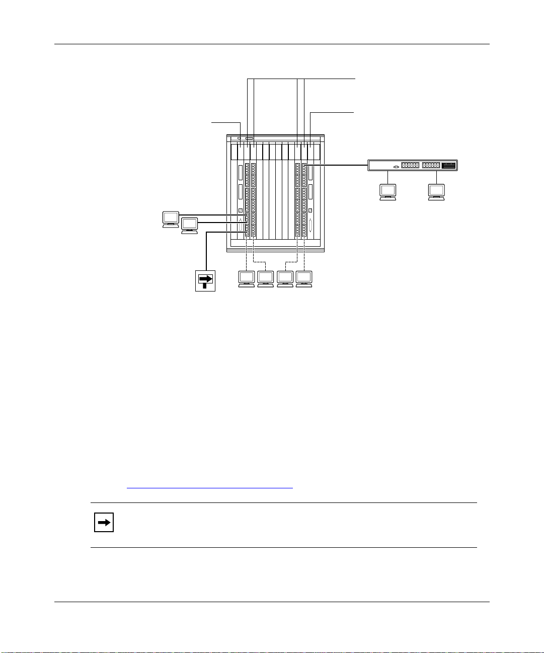
Figure 1-1. EtherSpeedII Switch Modules in a Network Center .................................1-2
Figure 1-2. Model 5625HD EtherSpeedII 24-Port Autonegotiating Switch Module ...1-5
Figure 1-3. Model 5000BH/BHC ATM/Ro uter Backplane Bus Structure ....................1-9
Figure 1-4. Model 5005BH ATM/Router Backplane Bus Structure .............................1-9
Figure 1-5. LEDs on the Model 5625HD Switch Module ..........................................1-10
Figure 2-1. Network Example .....................................................................................2-4
Figure 2-2. Connecting Servers to Dedicated Ports ...................................................2-5
Figure 2-3. Replacing a Bridge ..................................................................................2-6
Figure 2 -4. Desktop Switch with ATM Uplinks ............................................................2-8
Figure 2-5. Segment Switch in an Enterprise Network ..............................................2-9
Figure 2-6. Desktop Switch and Frame-to-Cell Converter ........................................2-10
Figure 2-7. Multi-Link Trunking Example ..................................................................2-11
Figure 3-1. Model 5000BH/BHC Chassis Backplanes .............................................. .3-3
Figure 3-2. Model 5005BH Chassis Backplanes ............ .......... .. ....... ....... ..... ....... ......3-4
Figure 3-3. Inserter/Extractor L evers in Vertical Position ...........................................3-6
Figure 3-4. Installing the Module ................................................................................3-7
Figure 3-5. Seating the Backplane Connectors .. ........................................................3-7
Figure 3-6. Releasing the Backplane Connectors ....................................................3-12
Figure B-1. MDI-X Internal Crossove r (RJ-45 Example) ...........................................B-2
Figure B-2. MDI-X to MDI-X External Crossover (RJ-45 Example) ...........................B-3
Figure B-3. 10BASE-T/100BASE-TX Ethernet UTP Crossover Cable ...................... B-4
Figure B-4. Fast Ethernet Type 1 Balun Media Adapter ............................................ B-6
Figure C-1. LED Display for the Model 5625HD Switch Module ................................C-1
Figure C-2. RJ-45 LEDs for the Model 5625HD Switch Module ................................C-3
206208-A
xi

xii
206208-A

Tables
Table 2-1. Factory Defaults for the Model 5625HD Switch Module ........................2-12
Table 3-1. Service Port Pin Assignments ...............................................................3-10
Table B-1. 10BASE-T/100BASE-TX MDI-X Port Pin Assignments ..........................B-4
Table B-2. Pairs in an RJ-45 Crossover Cable .........................................................B-5
Table C-1. LEDs on the Model 5625HD Switch Module ...........................................C-2
206208-A
xiii

xiv
206208-A

Preface
™
This guide provides an overview of the Nortel Networks
EtherSpeedII 24-Port Autonegotiating Switch M odule and information about
installing the module . This switch module introduces high-density Ethernet 10/
100 autonegoti ation frame switching into the Model 500xBH/BHC ATM/Router
Backplane.
Model 5625HD
The Model 5625HD switch module incorporat es current System 5000
Centillion™ EtherSpeedII™ technologies and the features described in “Features of
the Model 5625HD Switch Module” on page 1-3.
Configuring the EtherSpe ed switch modules is described in Using SpeedView 4.0
for Windows and Release Notes for SpeedView 4.1. For more information about
this topic, see “Related Publications
Before You Begin
This guide is intended for local area network administrators who are responsible
for installing, configuring, or maintaining a network and have the following
background:
• Familiarity with Ethernet net wor k administration
• Familiarity with t he tools and pr ocedures f or in stalli ng and ope rat ing sens iti ve
electronic equipment
• Understanding of Nortel Networks network management concepts and
terminology
” on page xvi.
™
and
206208-A
xv

Using the Model 5625HD EtherSpeed Switch Module
Related Publications
For informatio n about the Centillion switches, refer to the following related
publications:
• Using SpeedView 4.0 for Windows (Bay Networks
Describes this application,
• Release Notes for Centillion Platform 4.1
(Bay Networks part number 203315 -B)
Describes the updates to the SpeedView application for the 4.1 software
release.
• Reference Guide for the Centillion 50/100 and Model 5000BH Switches
(Bay Networks part number 893-01006-C)
Provides referen c e info rm ation about switching terminology and concepts;
describes conf iguration examples using Centillion 50/100 and Model
500xBH/BHC switches.
• Reference Guide for the Centillion Command Line Interface 4.0
(Bay Networks part number 893-00985-C)
which is used for configuring the module.
®
part number 893-891-D)
xvi
Describes setup and configur ation procedures for Centillion switches using
the command line interface.
• Installing the Model 5000BH ATM/Router Backplane
(Bay Networks part number 893-00949-A)
Provides installation instructions for the Model 5000BH ATM/Router
Backplane in the Model 5000 chassis.
• Installing the Model 5005BH ATM/Router Backplane
(Bay Networks part number 893-01056-A)
Provides installation instructions for the Model 5005BH ATM/Router
Backplane in the Model 5005 chassis.
• Installation and Refere nce for the Model 5000 Chassis
(Bay Networks part number 893-598- C )
Provides installation instructions and m aintenance information for the
Model 5000 Chassis.
206208-A

Preface
• Installation and Refere nce for the Model 5005 Chassis
(Bay Networks part number 893-696- A)
Provides installation instructions and m aintenance information for the
Model 5005 Chassis.
• Release Notes for the Centillion Platform Releas e 3.2
(Bay Networks part number 896-00189-C)
You can print selected technical manuals and release notes free, directly from the
Internet. Go to support.baynetw ork s.c om/library/tpubs/. Find the product for
which you need documentation. Then locate the specific category and model or
version for your hardw are or softwa re product. Using Adobe Acrobat Reade r , you
can open the manuals and release notes, search for the sections you need, and prin t
them on most standard printers. You can downloa d Acrobat Reader free from the
Adobe Systems Web site, www.adobe.com.
You can purchase selected documentation set s, CDs, and tec hnical publications
through the collater al catalog. The catalog is located on the World Wide Web at
support.baynetworks.com/catalog.html and is divided into sections arranged
alphabetically:
206208-A
• The “CD ROMs” section lists available CDs.
• The “Guides/Books” section lists books on technical topics.
• The “Technic al Manuals” section lists available printed documentation sets.
xvii

Using the Model 5625HD EtherSpeed Switch Module
How to Get Help
If you purchase d a se rvi ce con t ract fo r your Nortel Networks product from a
distributor or authorized reseller, contact the technical support staff for that
distributor or reseller for assistance.
If you pu rchased a Nortel Networks servic e program, contact one of the following
Nortel Networks T echnical Solutions Center s:
Tec hnical Solutions Center Telephone Nu mber
Billerica, MA 800-2LANWAN (800-252-6926)
Santa Clara, CA 800-2LANWAN (800-252-6926)
Va lbonne, F rance 33-4-92-96-69 -68
Sydney, Australia 61-2-9927-8800
Tokyo, Japan 81-3-5402-7041
xviii
206208-A

Chapter 1
Overview of the Model 5625HD Switch Module
This chapter introduc es the Model 5625HD EtherSpeedII 24-P ort Autonegotia ting
Switch Module and includes information about the following topic s:
• Overview of the EtherSpeedII switch module (this page)
• Features of the switch module (page 1-3
• Physical description of the switch module (page 1-5
• Switch configuration and manage ment (page 1-6
• Model 500xBH/BHC backplane architecture (page 1-9
)
)
Overview of the Eth erSpeedII Switch Module
EtherSpeedII switch modules provide 10/100 megabits per second (Mb/s)
autonegoti ation ports that support serve rs, routers, or dedicated connec tions to
users (Figure 1 -1
shared-media hub connect ion to a port.
Each EtherSpeedII switc h module is installed in a single slot of a Model 500xBH/
BHC chassis. You can use SpeedView
configure and manage the modules.
). The switch modules can also support multiple users through a
™
network mana g em ent so ft ware to
)
)
206208-A
1-1
Using the Model 5625HD EtherSpeed Switch Module
Model 5720M ATMSpeed
MDA MCP Module
Model 5625HD EtherSpeed 10/100
24-Port Autonegotiating
Switch Modules
Model 5720M ATMSpeed
MDA MCP Module
BayStack Ethernet Hub
9342EA
Model 5000BH
chassis
Router
100 Mb/s
UTP 10/100 connections
to users
Figure 1-1. EtherSpe e dII Switch Modules in a Network Center
The Model 5625HD switch module provide s 24 RJ-45 10/100 Mb/s
autonegoti ating switched Ethernet connect ions for the Model 500xBH/BHC
ATM/Router Backplane for the System 500x chassis. The switch module
combines the powerful ATM capabilities of the Centillion platform with the
connectivity features of the Model 500xB H chassis.
For Ethernet connec tivity, the Model 5625HD switch module RJ-45 connectors
accept Categor y 3 and 5 unshielde d twisted pair (UTP) or shielded twisted pair
(STP) cable connections. For more information about cabling, refer to
Appendix B, “
Cables and Connectors.”
1-2
Note:
Category 3 UTP cable can be used only for fixed 10 Mb/s port
operation. It is not used for 100 Mb/s or 10/ 100 autonegotiat ing port operation.
206208-A

Overview of the Model 5625HD Switch Module
Features of the Model 5625HD Switch Module
The Model 5625HD switch module off ers the following feature s:
• Wire-speed, port-to-port, packet transfer
• Single-slot design to fit into the System 500xBH/BHC chassis
• Autonegotiation of Ethernet 10/100 Mb/s speed
• Autonegotiation of half- or full-duplex mode on dedicated switch ports
• Layer 2 MAC-based switching
• Local frame switching, module-to-module switching, backplane switching,
and riser switching
• 200 MHz RISC processor
• 24 RJ-45 UTP network interface connectors
• Front-panel LEDs to indicate module and port operational status
• Port-based virtual LANs (VLANs)
• Protocol-based VLANs
206208-A
Protocol-sensitive VLANs classifies packets based on protocol types. Most
customers have multiple protocols per LAN segment , so a swit ch port needs
to support multiple VLANs based on different protocol type s. This feature
allows you to separa te data base d on pro tocols and not on ph ysica l limit ations.
• IEEE 802.1Q Ta g Recognition Support
The Model 5625HD switch module supports recog nition of VLAN tagged
frames based on IEEE 802.1Q tags. Frames entering a Model 5625HD switch
module port that contain an 802.1Q tag are mapped to a corresponding
VLAN. Based on the final destination, the frame is sent as either an
Ethernet-type fra me or an 802.1Q VLAN tagged frame. VLAN membership
is to be assigned by any combination of port with either tag or protocol.
• Support for IEEE 802.1d Spanning Tree
• Content-addressable memory (CAM) support for 8192 entries
• Port steering/port mirroring
• Input and output filtering supported by switching software
• Hardware support for IP multicast
1-3

Using the Model 5625HD EtherSpeed Switch Module
• Support for RMON Management Information Base (MIB)
– Ethernet Statistics Group
– Ethernet History Group
– Ethernet Alarm Group
– Ethernet Event Group
• Ability to install, remove, and replace a module in an operational chassi s
(hot-swap)
• Hardware Assist Multi-Protocol over ATM (MPOA)
MPOA is the ATM Forum standard that specifies a method to efficiently
transport intersubnet unicast data in a LANE environment. MPOA uses
LANE and NHRP processes to allow dire ct shortcut virtual channel
connections (VCCs) to be established for inter subnet communication without
requiring pass age through a router. The intrasubnet communication continues
to be supported over LANE. For IP, Nortel Networks has adopted MPOA as
the standard to implement layer 3 switching in an ATM network.
• Improved performance in segmentation and reassembly (SAR) to 3.2 gigabit
• Multi-Link Trunking (MLT)
1-4
206208-A
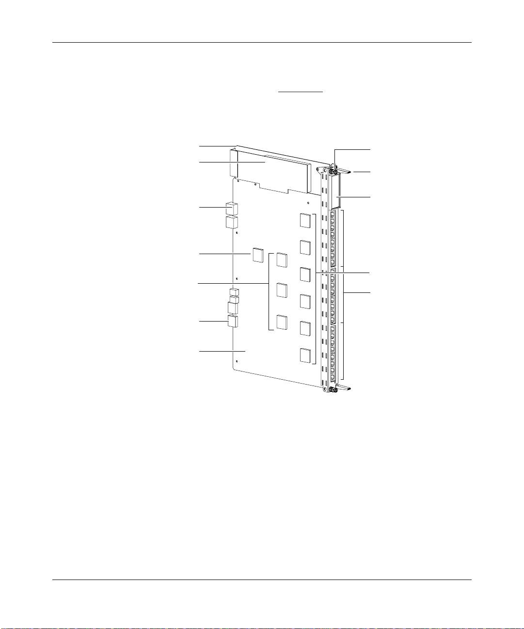
Physical Description
The Model 5625HD switc h module (Figure 1-2) consists of a printed c ircuit boa rd
with a metal module faceplate . The module inc ludes captiv e retaining screws and
inserter/extractor levers on the top and bottom of the front panel.
Overview of the Model 5625HD Switch Module
Metal frame
Power supply
Model 5000BH
backplane connector
3.2 Gb/s SAR
MAC
(Media Access
Controller)
Common
Management
Bus connector
Circuit board
Captive retaining
screw
Inserter/extractor
lever
LED display
matrix
Phy
10/100BASE-TX
ports
9362FA
Figure 1-2. Model 5625HD EtherSpeedII 24-Port Autonegotiating Switch
Module
206208-A
1-5

Using the Model 5625HD EtherSpeed Switch Module
There are 2 4 RJ-45 ports on the Model 5625HD switch module that automatically
detect speed and duplex mode. (For more information a bout cables, refer to
Appendix B, “
Cables and Connectors.”)
Each Model 5625HD switch module oc cupies one slot in a Model 500x BH/BHC
chassis. You can install a maximum of 10 Model 5625HD switch modules, along
with two master control processor (MCP) switch modules, in a Model 5000BH/
BHC chassis or a maximum of five Model 5625HD switch modules, and one
MCP switch module, in a Model 5005BH chassis.
Switch Configuration and Management
You manage and configure a Model 5625HD switch module through access to an
installed MCP module in the Model 500xBH/BHC chassis with the following
network management features:
• SpeedView for Windows 4.1 and greater
• Command line interface (CLI)
• Simple Network Management Protocol (SNMP) agent with Sy stem 5000 MIB
extensions
1-6
• Trivial Fi le Transfer Protoc ol ( TFTP) support
SpeedView
®
SpeedView is a network management application that runs on Microsoft
Windows® 95 or Windows 98 and Windows NT® and provides a graphical user
interface to set up your switch. SpeedView allows you to monitor and control
network traffic and to perform advanced operations such as filter configuration.
For more information about SpeedView, refer to Using SpeedView 4.0 for
W indows and Release Notes for Spe edView 4.1.
Optivity Network Management S ystem
™
(NMS) provides enterprise-wide
configura tion and monitoring support for the Model 500xBH/BHC chassis
switches. Configuration support is provided using SpeedV iew, which is integrated
with Optivity NMS. Expanded View
™
, OmniView™, Network Atla s™, Threshold
Manager™, and other Optivity® applications pro vide comprehensive monitoring
and troubleshooting suppor t. For more information about Optivity network
management software , r efe r to your Optivity documentation.
206208-A

Overview of the Model 5625HD Switch Module
Command Line Interface
The CLI provides an out-of-band interface for the initial setup of basic
configura tion parameters such as IP address and bridging mode. For more
information about the CLI structure and commands, refer to Reference Guide for
the Centillion Command Line Inte rface.
SNMP MIB Support
The System 5000BH/BHC MCP modules support an SNMP-compatible agent
with private MIB extensions. Built-in SNMP agent support ensures compatibility
with existing net work management tools. The MCP modules support MIB-I and
MIB-II (RFC 1213) standards that provide access to detailed management
statistics .
Using SpeedView, you can configure SNMP traps to be generated automatically
for conditions such as unau thorized access attempt s or changes in oper ating status
on individu al ports.
TFTP Support
TFTP is a supported Tr ansmission Control Protocol/Internet Protocol (TCP/IP)
service used to download software and configuration information to the MCP
module memory. TFTP allows you to transfer an updated switch agent and
configuration files from a remote server to flash memory. You can perform a
transfer over the network or through a serial connec tion to the installed MCP
module.
Spanning Tree Protocol 802.1d Support
The Model 5625HD switch module software supports the Spanning Tree Protocol
as specifi ed in the IEEE 802. 1d sta ndard. The Spanning Tree Protocol is
implemented to detect and eli minate logical loops in a bridged or switched
network. When multiple paths exist, the spanning tree algorithm configures the
network so that a bridge or switch use s only the most efficient path. If that path
fails, the protocol automatically reconfigures the network to make another path
become active, thus sustaining network operations.
206208-A
1-7

Using the Model 5625HD EtherSpeed Switch Module
Support for Virtual LANs
Using the Model 5625HD switch module, you can group one or more physical
ports to form a virtual LAN that constitutes a single broadcast domain.
V irtual LANs (VLANs) are formed when broadcast domains are configured
across multiple switches. Each Ethernet segm ent is an independent physical
segment with its o wn collis ion domain, b ut all segm ents withi n a VLAN appear to
the user as a broadcast domain.
Filtering
Filtering capabi lities for the Model 5625HD switch module are implemented in
system hardware and controlled by system software. Refer to the appropriate
Centillion relea se guides for descriptions of the supported filtering capabilities,
features, and availability.
Hot-Swapping Capability
A Model 5625HD switch module can be inserted into or removed from a chassis
without interrupting service to other modules within the Model 500xBH/BHC
chassis. This feature is called “hot-swapping.”
1-8
Caution:
the ports through the management inte rface, prior to hot-swapping.
Be sure to remove cables from all ports on the module, or dis able all
206208-A

Overview of the Model 5625HD Switch Module
About the Model 500xBH/BHC Backpl ane
The Model 500xBH/BHC ATM/Router Backplane integrates the two bus
technologies shown in Figure 1-3 and Figure 1-4.
The Model 5000BH and 5000B HC backplanes are identical with the
Note:
exception of an additional shared 100 Mb/s backplane on the Model
5000BHC. The Model 5625HD switch module does not connect to these
shared backplanes. The Model 5625HD sw itch module can be used with the
Model 5000BH and 5000BHC backplanes without altering the module’ s
performance.
PPX router bus
Centillion ATM bus Centillion ATM bus
Slot 2345678910111213
6750EC
206208-A
Figure 1-3. Model 5000BH/BHC ATM/Router Backplane Bus Structure
PPX router bus
Centillion ATM bus
Slot 234567
7849EA
Figure 1-4. Model 5005BH ATM/Router Backplane Bus Structure
1-9

Using the Model 5625HD EtherSpeed Switch Module
LEDs
LEDs on the module indicate port operat ing status and speed (Figure 1-5). The
numbers on the LEDs correspond to the port num bers. For more information
about the operation of the LEDs, refer to Appendix C, “LEDs.”
Annunciator
Port number
Port speed
Port LEDs
5625HD
10/100 Switch Host
Port Status
131001
141002
151003
161004
171005
181006
191007
201008
211009
2210010
23100
2410012
100
100
100
100
100
100
100
100
100
100
10011
100
9341EA
Figure 1-5. LEDs on the Model 5625HD Switch Module
10/100 Mb/s UTP Autonegotiation Ports
A Model 5625HD switch module contains 24 10/100 Mb/s autone gotiating
Ethernet ports with shielde d RJ-45 connectors. The RJ-45 connectors acc ept
Category 3 and 5 UTP or STP cable and are wired as MDI-X por ts to connect end
stations to patch pa nels, wit hout using crosso v er cab les. See Appendix B, “Cables
and Connectors,” for inform ation about wiring and pin assignments.
1-10
206208-A

Chapter 2
Planning a Network with the Model 5625HD
Switch Module
Installing the Model 5625HD EtherSpeedII 24-Port Autonegotiating Switch
Module in a network can significantly improve LAN performance. This chapter
provides infor mation to help you plan a network that uses this module. The
chapter includes the fo llowing topics:
• Physical configurat ion guidelines (this page)
• Typic al network config uration examples (page 2-3
• Factory-set and predef ined configurati ons (p age 2-12
Physical Configuration Guidelines
Follow the basic guidelines in Appendix A, “Technical Specifications,” and
Appendix B, “Cables and Connectors,” when you plan a network using the
Model 5625HD switch module.
)
)
206208-A
2-1

Using the Model 5625HD EtherSpeed Switch Module
Connecting to Ethernet Hubs and Network Devices
You connect the ports of the Model 5625HD switch module to the front panel,
wired as MDI-X connections. This wiring allows you to use a straight-thr ough
cable between the Model 5625HD switch module and the patch panel.
To connect the ports on the patch panel to another Ethernet switch or an Ethernet
hub, follow these guidelines:
• Personal computers (PCs) and servers typically have network interfa ce
controllers (NICs) that are configured as MDI connections. To connect these
devices, use a straight-through cable.
• Hubs and other switches typically have connectors that are configured as
MDI-X. Some hubs and switches have port s that are set by a toggle switch for
either MDI or MDI-X operation.
— To connect a port set for MDI-X to the Model 5625HD switch module
port, use a crossover cable.
— To connect a port set for MDI to the Model 5625HD switch module port,
use a straight-thr ough cable .
2-2
For connector spec ifications for MDI-X ports, refer to Appendix B, “
Connectors.”
Cables and
206208-A

Planning a Network with the Model 5625HD Switch Module
Network Configuration Examples
The Model 5625HD switch module is an adaptable switc h suitable for use in
wiring closets or networ k cente rs in conjunction with the Model 500xBH/BHC
chassis. Figure 2-1 shows an example of Model 5625HD switch modules in a
sample network configuration.
This section describes the following Ethernet switching applications:
• Ded icat ed po rt s for serve rs (page 2-5
• Replacement for a bridge port (page 2-6
• Desktop switch with ATM uplinks in a wiring closet (page 2-7
)
)
)
• Segment switch in a wiring closet with ATM uplinks to a network center
switch (page 2-9
• Desktop switch and frame-to-cell converter (page 2-10
)
)
206208-A
2-3

Using the Model 5625HD EtherSpeed Switch Module
Model 5000BH Chassis
Redundant,
load-balanced
risers to closets
Model 5625HD
Switch Modules
Network
Center
Router
ATM
Redundant,
network center
switches
Figure 2-1. Network Example
2-4
Model 5000BH Chassis
ATM
VLAN D
Enterprise servers
Workgroup
servers
A
B
10/100 Mb/s
C
9380EA
206208-A

Planning a Network with the Model 5625HD Switch Module
Giving a Server a Dedicated Port
Moving a server from a 10 Mb/s shared-media connection to a dedicated port
on the Model 5625HD switch module impro ves server response time and
increases through put capa city. For even higher performance, the serve r could
be upgraded to 100 Mb/s and the Model 5625HD switch module would
autonegoti ate for 100 Mb/s.
In Figure 2-2
, the “Before” example shows clients and servers sharing the same
network segment. The “After” example shows the same clients assigned to
differ ent segments through a shared hub (either 10/100 Mb/s or directly
connected) and the origi nal servers connected to switch ports on a Model
500xBH/BHC chassis. In addition, two servers have been added through 10/100
Mb/s connections.
Before
Clients
Segment
10 Mb/s
100 Mb/s
Servers
After
Clients
Model 5625HD EtherSpeed 24-Port
10/100 Autonegotiating
Switch Modules
Model 5720M ATMSpeed
MDA MCP Module
10 Mb/s
Servers
100 Mb/s
Segment
10 Mb/s
clients
Segment
100 Mb/s
clients
10 or 100 Mb/s
clients
Figure 2-2. Connecting Servers to Dedicated Ports
206208-A
100 Mb/s
Servers
9344EA
2-5

Using the Model 5625HD EtherSpeed Switch Module
Replacing a Bridge
Using a switch instead of a bridge in the network can increase the aggregate
network bandwidth. The “After” example in Figure 2-3 shows one server
connected to a dedicated 10BASE-T port. It also shows the other server and
additional clie nts attached using dedicated 100BASE-TX connections. This
network conf iguration allo ws you to have switched 10 Mb/s Ether net along with
segmented 10 Mb/s Ethernet to conserve ports.
Before
Clients
Servers
Clients
Segment
10 Mb/s
clients
Segment
100 Mb/s
clients
Segment
10 Mb/s
100 Mb/s
10 or 100 Mb/s
clients
Bridge
After
Segment
Model 5625HD EtherSpeed 24-Port
10/100 Autonegotiating
Switch Modules
Model 5720M ATMSpeed
MDA MCP Module
10 Mb/s
Server
100 Mb/s100 Mb/s
Server
9345EA
Figure 2-3. Replacing a Bridge
2-6
206208-A

Planning a Network with the Model 5625HD Switch Module
Desktop Switch with ATM Uplinks
In the example shown in Figure 2-4, the Model 5625HD switch module provides
up to 24 RJ-45 switched Ethernet (10/100 Mb/s) ports to connect to desktops, with
redundant high-spee d ATM OC-3c and OC-12c ports to connect to an ATM
backbone. This network configuration can support small to large wiring closets.
Figure 2-4 on page 2-8
shows a sample network providing ATM uplinks to a
Model 5000BH/BHC chassis. Servers are connected to the network through the
Model 5000BH/BHC chassis, and network station s are connected to the 10/
100BASE-T ports on the Model 5625HD switch modules. The chassis are
dual-homed with ATM OC-3c and OC-12c uplinks to the Model 5000BH/BHC
chassis. Model 5000BH/BHC chassis can be interconnected with multiple ATM
links.
206208-A
2-7

Using the Model 5625HD EtherSpeed Switch Module
Data Center
Servers
Wiring Closet
Model 5000BH chassis Model 5000BH chassis
100 Mb/s
100 Mb/s
ATM ATM ATM ATMATMATM
Model 5000BH
chassis
10 Mb/s 10 Mb/s
100 Mb/s100 Mb/s
100 Mb/s100 Mb/s
ATM
ATM
Servers
100 Mb/s
100 Mb/s
10 or 100 Mb/s attached clients
Figure 2-4. Desktop Switch with ATM Uplinks
2-8
9346EA
206208-A

Planning a Network with the Model 5625HD Switch Module
Segment Switch in an Enterprise Network
To achieve a gradual transition from shared media to switched networks, you can
use the Model 5625HD switch module to aggregate traffic from stations
connected to one or more hubs. Figure 2-5 shows such a network with switches
used to connect shared-media hubs to a backbone switch. Stations connected to
the Model 5000BH/BHC switch are associated with different segments thr ough
the configur ation switching feature.
Data Center
Wiring Closet
Shared-media
Model 5000BH
Chassis
Model 5000BH Chassis with shared-media modules
Model 5625HD EtherSpeed 24-Port 10/100
Autonegotiating Switch Modules
Servers
100 Mb/s
100 Mb/s
10 Mb/s
100 Mb/s
10 Mb/s
BayStack
ATM Router
ATM
Hubs
Clients
Figure 2-5. Segment Switch in an Enterprise Network
206208-A
9347EA
2-9

Using the Model 5625HD EtherSpeed Switch Module
Desktop Switch and Frame-to-Cell Converter
For wiring closets with higher densities and lower bandwidth requirements, you
can use the Model 5625HD switch module to aggregate traffic from other
stackable switch pr oducts such as the BayStack 301 and BaySt ack 350T switches
(providin g frame switching) to an ATM backbone (providing cell switching). The
stackable switches and the 24 RJ-45 10/100 M b/s switched Ethernet ports on the
Model 5625HD switch module provide desktop connectivity.
Figure 2-7
shows a ne twor k with a Model 56 25HD swit ch module u sed to conne ct
BayStack 301 and 350T switches to the Model 5000BH/BHC chassis in a data
center. The 10/100 Mb/s ports on the Model 5625HD switch module provide
high-speed connect ions to the BayStack™ switches. The Model 5625HD switch
module provides swit ched 10 Mb/s or 100 Mb/s capability for higher-bandwidth
desktop connecti vity and can upgrade to 100 Mb/s with a client NIC upgrade.
Data Center
Server
Wiring Closet
Model 5000BH chassis Model 5000BH chassis
100 Mb/s 100 Mb/s
ATM ATM
100 Mb/s
BayStack 301
switch
ATM
Model 5000BH chassis with
Model 5625HD EtherSpeed 24-Port 10/100
Autonegotiating Switch Modules
100 Mb/s
BayStack 350T
switches
350F 10/100 Autosense Switch
Server
350F 10/100 Autosense Switch
2-10
10/100 Mb/s
clients
Figure 2-6. Desktop Switch and Frame-to-Cell Converter
9348EA
206208-A

Multi-Link Trunking
Multi-Link T runking (MLT) allows up to four physical connections for the same
media type and speed to be grouped and treated as a single logical link. MLT
improves pe rformance between two switches or between a switch and a serv er.
ML T allows data to be carried over multiple 100 Mb/s full-duplex links connect ed
to the same device, thus improving performance. Figure 2-7
connecting multiple BayStack 450 ports into a Model 5625HD switch module
allows the data to load share across those multiple ports, a nd overall performance
is imp r ov e d .
Planning a Network with the Model 5625HD Switch Module
shows that
Model 5005BH Chassis
BayStack 450-24T
100 Mb/s
100 Mb/s
MLT
connection
Figure 2-7. Multi-Li nk Trunking Example
9381EA
206208-A
2-11

Using the Model 5625HD EtherSpeed Switch Module
Default Port Configuration
The Model 5625HD switch module is shipped preconfigured with the settings
listed in Table 2-1.
Table 2-1. Factory Defaults for the Model 5625HD Switch Module
Parameter Fac to ry Default Configurable Options
Switching mode Transparent Transparent
Spanning Tr ee Protocol None None, IEEE
State Enable Enable/Disable
Filters Disable (none) Enable/Disable
Port speed/display Auto Auto 10/100
Spanning tree group 2 2–32
Priority 128 0–255
Path cost 10 1–65535
Predefined SpeedView Configuratio ns
2-12
SpeedView offers sever al predefined configurations. You may simply choose one
of these without hav ing to configure individual ports. Predefined configurations
are av ailable for the follo wing app lications:
• All transparent switching with no Spanning Tree support
• All transparent switching with IEEE 802. 1d Spanning Tree support
You must enter additional configur ation information if you are using any of the
following f eatures:
•ATM
• VLANs
• Filtering
• Combinations of bridging modes and Spanning Tree Protocol not offered as
defaults
Instructions for using these features appear in Using SpeedView 4.0 for Windows
and Release Notes for SpeedView 4.1.
206208-A

Chapter 3
Installing the Model 5625HD Switch Module
This chapter describes how to install a Model 5625HD EtherSpeedII 24-Port
Autonegotia ting Switch Module in the Model 500xBH/BHC chassis a nd inc ludes
the follo wing information and procedures:
• Arranging Model 5625HD switch modules in a Model 500xBH/BHC chassis
(this page)
• Using required tools for installation (page 3-5
• Installing a switch module (page 3-6
• Checking module LEDs (page 3-8
• Making 10/100 Mb/s connections (page 3-8
• Connecting terminals and management stations (page 3-9
• Checking the module connection to the backplane (page 3-11
• Removing and replacing a switch module (page 3-11
)
)
)
)
)
)
)
206208-A
3-1

Using the Model 5625HD EtherSpeed Switch Module
Arranging Modules in a Model 500xBH/BHC Chassis
The Model 5000BH ATM/Router Backplane has two Centillion ATM b uses and a
PPX bus to accommodate switch and router modules. The Centillion ATM buses
span two slot ranges in a Model 5000BH/BHC chassi s: slots 2 through 7 and 8
through 13. When you install a Model 5625HD switch module in one of these slot
ranges, you must also install an MCP switch module (such as the Model 5720M
ATMSpeed
System 5000 switch modules (one of which must be an MCP module) to each
Centillion ATM bus in a Model 5000BH/BHC chassis.
The PPX bus spans slot s 2 through 13. A router module may be installe d in any of
these slots. Router modules for the Model 5000BH ATM/Router Backplane
include the Model 5380 Ethernet Router Module, the Module 5580 Token Ring
Router Module, and the Model 5782 Centillion Multipr otocol Engine Module.
Any slot designated f or switch modules can also be used for a standard Ethernet,
token ring, or FDDI, or ATM module with the appropriate backplane(s) installed
in the chassis.
™
MCP module) in the same range of slots. You can attach up to six
3-2
206208-A

Figure 3-1 sho ws the logical relationship be tween the Model 5000BH ATM/
Router Backplane and shared-m edi a backplanes in a Model 5000BH/BHC
chassis.
Slot 2 Slot 13
Installing the Model 5625HD Switch Module
PPX bus (2–13)
Centillion
ATM bus (2–7, 8–13)
Fast Ethernet (1–14)
Power
Common
management bus
Ethernet (1–14)
Token ring
(1–14 or 1–7, 8–14)
Slot 1
Slot 14
Figure 3-1. Model 5000BH/BHC Chassis Backplanes
Note:
The Model 5000BH and Model 5000BHC backpla nes are ide ntica l with
the exception of an additional shared 100 Mb/s backplane on the Model
5000BHC. The Model 5625HD switch module does not connect to this sha red
backplane. The Model 5625HD switch module can be used with the Model
5000BH and Model 5000BHC backplanes without altering the module’ s
performance.
Model
5000BH
backplane
Model
5000BHC
backplane
Model
5000BH
backplane
8662EA
206208-A
3-3

Using the Model 5625HD EtherSpeed Switch Module
The Model 5005BH ATM/Router Backplane (see Figure 3-2) has a single
Centillion ATM bus and PPX® bus. The Centillion ATM bus spans slots 2 through
7 in the Model 5005BH chassi s. Whe n you install a System 5000 Model 5625HD
switch module in one of these slot ranges, you must also ins tall an MCP switch
module (such as the M odel 5720 M ATMSpeed MCP module) in the same r ange of
slots. You can attach up to six System 5000 switc h modules ( one of which must be
an MCP module) in a Model 5005BH chassis.
The PPX bus spans slots 2 through 7. A router module may be installed in any of
these slots. Router modules for the Model 5000BH ATM/Router Backplane
include the Model 5380 Ethernet Router Module, the Module 5580 Token Ring
Router Module, and the Model 5782 Centillion MultiProtoc ol Engine Module.
Any slot designated f or switch modules can also be used for a standard Ethernet,
token ring, or FDDI, or ATM module with the appropriate backpla ne(s) installed
in the chassis. Slot 1 is reserved for the clock module.
Figure 3-2
shows the logical rela tionship between the Model 5005BH ATM/
Router Backplane and shared-m edi a backplanes in a Model 5005BH chassis.
Slot 2 Slot 7
PPX bus (2–7)
Centillion
ATM bus (2–7)
Power
Common
management bus
Ethernet (1–8)
Token ring (1–8)
Slot 1 Slot 8
Model
5005BH
backplane
Model
5005BH
backplane
8749EA
3-4
Figure 3-2. Model 5005BH Chassis Backplanes
206208-A

Required Tools and Equipment
You need the following tools and equipment to install a Model 5625HD switch
module:
• Medium flat-tip screwdri ver
• Grounded antistatic mat and wrist strap or discharge leash
Installing the Model 5625HD Switch Module
Caution:
The System 5000 equipment uses electronic components that are
sensitive to static electricity. Static discharge from your clothing or other
fixtures a round y ou can ca use damage . Take all possible p recaut ions to pr e vent
static discharge damage when working with printed circuit boards.
Place each module on a grounded antistatic mat until you are ready to install
the module. If you do not have an antistatic mat, wear a wrist strap or
discharge leash to f ree yourse lf of s ta tic bef ore t ouching an y of the modules, or
free yourself of static by touching the metal chassis before handling the
module.
206208-A
3-5

Using the Model 5625HD EtherSpeed Switch Module
Installing the Switch Module
To install and secure the Model 5625HD switch module in the chassis:
Remove the f iller panel from the chassis slot where you intend to install
1.
the module.
Extend the switch module inserter/extractor levers to the vertical position
2.
(Figure 3-3 ).
3-6
4689
Figure 3-3. Inserter/Extracto r Levers in Vertical Position
These instructions illustrate installing a Model 5625HD switch module
Note:
in a Model 5000BH/BHC chassis. The instructions also apply to a Model
5005BH chassis.
Align the top and bottom edges of the metal printed circuit board carrier
3.
with the slot card guides at the top and bottom of the slot.
Slide the switch module into the chassis until you feel it engage the
4.
backplane (Figure 3-4).
The inserter/e xtractor lev ers should still be in the vertical position and in
contact with the front of the chas sis. Do not push the switch module all the
way into the chassis.
206208-A

Installing the Model 5625HD Switch Module
3649.1
Figure 3-4. Installing the Module
Rotate the inserter/extractor levers in toward the center of the switch
5.
module front panel to seat the backplane connectors (Figure 3-5).
206208-A
Model 5000
4690.2
Figure 3-5. Seating the Backplane Connectors
Use the flat-tip screwdriver to tighten the captive retaining screws at both
6.
ends of the switch module front panel.
3-7

Using the Model 5625HD EtherSpeed Switch Module
Checking LEDs
Immediately after you have installed a Model 5625HD switch module, watch the
LEDs on the front panel. If the board is installed and functioning properly, the
following LED col or sequence occurs:
• The annunciator lights amber and then lights green.
• The Port Status LEDs light green or amber for each port showing link sta tus
or port management disabled sta tus.
• Each Port Speed LED lights green when you have a 100 Mb/s Ethernet
connection and is off when you have a 10 Mb/s connection.
See Appendix C, “
LEDs,” for the LED definitions.
Making 10/100 Mb/s Connections
The 10/100 Mb/s jacks on the Model 5625HD switch module accept standard
UTP or STP cable connections.
To connect network devices to the 10/100 Mb/s ports on the Model 5625HD
switch module, follow the se guidelines:
• Use Category 3 or 5 UTP or STP cable with RJ-45 connectors for the ports on
the Model 5625HD switch module.
• Use straight-through cables to connect the networ k interface card (NIC) in a
PC workstation or server. These devices typically have MDI connectors.
• Use a crossover cable to connect to ports configured as MDI-X (such as
Ethernet hubs).
For more information about cables, connectors, and connector pin assignments,
see Appendix B, “
Cables and Connectors.”
3-8
206208-A

Installing the Model 5625HD Switch Module
Connecting Terminals and Management Stations
This section provides information about connecting terminals or PCs to the
service port on the Model 500xBH/BHC chassis. For information about
connecting a management station to an MCP module, refer to the using guide
shipped with that module.
Refer to Using SpeedView 4.0 for Windows and Release Notes for SpeedView 4.1
for information about advanced configuration and monitoring of the switch.
To connect a terminal to the Model 500xBH/BHC chassis se rvice port, you need
the follo wing equipment:
• A TTY-compatible terminal or a portable computer with a serial port and the
ability to emulate a TTY-compatible terminal. The terminal communication
parameters should be set for:
— 9600 baud (default)
— 8 data bits
— No parity
206208-A
— 1 stop bit
— No handshaking
— Standard ASCII code
• An RS-232 modem cable with a female DB-9 connector to connect to the
service port on the chassis front panel. The cable should use the service port
pin assignments that are spe cified in I nstallation and Reference for the
Model 5000 Chassis and Installation and Ref erence for the Model 5005
Chassis.
3-9

Using the Model 5625HD EtherSpeed Switch Module
The other end of the cable must hav e a connecto r appropr iate to the se rial port
on your computer or terminal. ( Most terminals or compute rs use a male DB-9
or DB-25 connector.) See Table 3-1
Note:
RS-232 signals on other pins (suc h as DTR, CTS, and CD) are ignored.
Table 3-1. Service Port Pin Assignments
Ter mi nal T o Service Port
DB-9 Pins DB-25 Pins Function DB-9 Pins Function
2 3 Receive dat a 2 Transmit data
3 2 Transmit data 3 Receive dat a
5 7 Signal ground 5 Signal ground
To connect the terminal to the chassis service port:
Connect the RS-232 cable to the terminal (or a computer in terminal-
1.
emulation mode) and to the chassis service port.
for the pin assignments.
3-10
Set the terminal communication parameters as described earlier in this
2.
section.
Turn on the terminal; adjust contrast and brightness as required.
3.
206208-A

Installing the Model 5625HD Switch Module
Checki ng the Module Connection to the Backplane
The Model 5625HD switch module communicates through the MCP
Note:
rather than the common management bus (CMB). Modules without the CMB
interface do not display on the Slot Selection menu, and there is no way to
verify that they are connected to the backplane using the service port menus.
Removing and Replacing the Switch Module
This section provides the following information and procedures:
• Conditions for replacing a Model 5625HD switch module
• Removing a Model 5625HD switch module
• Installing the replacement Model 5625HD switch module
Conditions for Replacing a Switch Module
The following hardware conditions indic ate that the switch module needs to be
replaced:
• The annunciator on the front panel remains off . This c ondition indic ate s that a
hard w ar e rese t i s a ctive or that th e module is not receiving +5 volt power.
• The annunciator remains amber. This condition indicate s that the module has
failed to boot.
For information about using LEDs to trouble shoot an EtherSpeed switch module,
see Appendix C, “
For information about troubleshooting other System 500x modules, refer to the
using guide for the specific module.
LEDs.”
206208-A
3-11

Using the Model 5625HD EtherSpeed Switch Module
Removing a Switch Module
To remove a Model 5625HD switch module f rom the chassis:
Be sure to remove cables from all ports on the module, or disable all the
Note:
ports through the management interface, prior to hot-swapping.
Use a flat-tip screwdriver to loosen the two captive r etaining screws that
1.
secure the module to the chassis.
These screws are spring-loaded to pop outward when they are unscrewed from
the chassis. The scre ws are held in place on the module front panel by loc king
washers.
Rotate the top and bottom inserter/ extractor lev ers away from the center
2.
of the switch front pa ne l to releas e th e mod ul e from the ba ck pl ane
connectors (Figure 3-6).
Model 5000
3-12
Captive retaining
screw
Inserter/extractor
lever
3249.10
Figure 3-6. Releasing the Backplane Connectors
206208-A

Installing the Model 5625HD Switch Module
Slide the Model 5625HD switch module out of the chassis.
3.
Hold the front panel with one hand whil e you suppor t the b ottom of the s witch
module with the other hand.
Place the Model 5625H D switch modu le on an antist atic mat until y ou ar e
4.
ready to put it back into the chassis.
If you are not inst alling another Model 5625HD switch module, install a
5.
fille r panel over the empty slot.
Installing the Replacement Switch Module
To install the replacement switch module, follow the procedure described in
“Installing the Switch Module” on page 3-6.
Reconfiguring the Replacement Switch Module
The Model 5625HD switch module keeps the configuration of an identical
replacement module. If the repla cement is not a Model 5625HD switch module,
the module needs to be reconfigured after it has been replaced. Follow the
procedure describ ed in “
Installing the Switch Module” on page 3-6.
206208-A
3-13


Chapter 4
Troubleshooting
This chapter provide s suggestions for troublesh ooting pr oblems with a Model
5625HD EtherSpeedII 24-Port Autonegotiating Switch Module and includes the
following topics:
• Preliminary steps in troubleshoot ing (p age 4-2
• Incompatibility with the configuration of a previously installed module
(page 4-2
• Startup failure in the Model 5625HD switch module (page 4-3
• Problems with the port connection (page 4-4
To expedite support when you call Nortel Networks, please have the following
information ready:
• Hardware configurat ion
• Software configurat ion (including the image file version number and
SpeedView version number)
• Net wor k di agram
• Module or switch part number and serial number for the suspected module
• Brief description of the problem
)
)
)
)
206208-A
4-1

Using the Model 5625HD EtherSpeed Switch Module
Preliminary Steps
If you suspect problems with a newly installed Model 5625HD switch module,
start troublesh ooting by checking the following items:
• Check all power cable connections and power sources.
• Check network cable connections to be sure connectors are properl y seat ed .
• Make sure the cables are the correct type, with correctly wired connectors.
• Check the LEDs for indication of link status.
Previous Module Configuration Incompatibility
Symptom: A module in a powered-on chassis fails to start up.
The slot the module occ upies in t he System 500xBH/BHC chassis may hav e ha d a
differ ent module type installed in it previously.
The Model 5625HD switch module keeps the configuration of an identical
replacement module. If the repla cement is not a Model 5625HD switch module,
the module needs to be reconfigured after it has been replaced. Follow the
procedure describ ed in “
Installing the Switch Module” on page 3-6.
4-2
To check for possible incompat ibility in module type:
Connect a SpeedView management station to the MCP port on the
1.
switch, using either the direct connection or the modem connection.
This procedure is described in Using SpeedView 4.0 for W indows and Release
Notes for SpeedView 4.1.
Select the Map menu.
2.
If this module is displa yed wit h all p ort s disabl ed, t he MCP module is not a ble
to manage this module because there is no stored configuration infor mation
about the module. You must enable the ports and download the new
configura tion to the MCP module.
After you download the new configuration, you are prompted to reset the
switch.
206208-A

Model 5625HD Switch Module Startup Failure
Symptom: All LEDs are off on the Model 5625HD switch module.
This condition indicate s that the links on all ports are not functioning.
To resolve the probl em:
Use the CLI, SpeedView, or other network management tool to verify
1.
port status.
Ensure that all modules in the chassis are firmly seated and that the
2.
retaining screws have been tightened.
Remove and reinser t the fa i lin g mo du l e.
3.
If the problem persists , contact Nortel Networks customer suppor t. Be ready to
giv e the service representative the information listed on page 4-1
Troubleshooting
.
206208-A
4-3

Using the Model 5625HD EtherSpeed Switch Module
Port Connection Problems
Symptom: The LED on an Ethernet port is off.
If an LED does not light when traffic is present, there may be a port connection
problem.
To resolve the probl em:
Verify whether or not the port is enabled, using SpeedView or the CLI.
1.
From the Map window in SpeedView, choose Switch and then choose
a.
Configure.
When the configura tion information has been downl oad ed to the
management station, check the port state. The port state should be either
enabled or disabled.
From the Map window, choose Statistics.
b.
When the statistics infor mation has been downloaded to the management
station, check the port sta te. If the port state is Down, the port is receiving
no link signal or it is disabled.
4-4
From a configuration terminal connected to the serial port on the
c.
switch, access the CLI.
Use the
show port
command and specify the module number and port
number for the suspected port . When the port info rmation is displayed,
verify that port_state is up and SPTstate is forwarding.
Verify that the cable is correctly connected.
2.
Disconnect and res eat the ca ble at the Model 5625HD swi tch module port a nd
at the patch panel or punchdo wn block. Check the port LED for a change in
status.
206208-A

Troubleshooting
Verify that the port is transmitting and receiving data frames.
3.
Check the green RJ-45 LE D , whi ch ind ica tes a data ex ch a ng e.
a.
Refer to Appendix C, “
From the Map window in SpeedVie w, choose Statistics.
b.
LEDs,” for additional information.
When the statistics information is displayed at the management station,
verify that the octet counts for transmit and receive a re incrementing.
Also verify that the frame coun ts for transmit and receive unicast traffic
and for multicast traffic are increme nting.
From a configuration terminal connected to the serial port on the
c.
switch, access the CLI.
Use the show port command and specify the module number and port
number for the suspected port . Verify that the following counters are
incrementing:
• InOctet
• OutOctet
• InUcastPkt
• OutUcastPkt
• MulticastTrans mittedOk
• MulticastReceiv edOk
• BroadcastTrans mitt edOk
206208-A
• BroadcastReceiv e dOk
If the port still fails, try inserting it into an other switch network or
4.
shared segment.
If the port functions correctly, check the status of the fir st switch network
or shared segment.
If the port fails to function, contact Nortel Networks customer support. Be
ready to give the service representative the information listed on page 4-1
.
4-5


Appendix A
Technical Specifications
This appendix provide s technical specif ications for the Model 5625HD
EtherSpeedII 24-Port Autonegotiating Switch M odule. For connector pin
assignments and other information about cables, see Appendix B, “
Connectors.”
Cables and
Industry Protocols and
Standards
Interface Options
Data Rates
Autonegotiating Features
Microprocessor
Memory
Processing
Dynamically Allocated Buffer Pool
CAM (Content Addressab le
Memory)
SIMM Flash Memory
ISO/IEC 8802-3 (ANSI/IEEE 802.3) Fif th Edi ti on
1996-07-29
Clause 4: Medium Access Control and
Clause 14: Twisted-Pair Medium Attachment Unit
(MAU) and Baseband Medium Type 10BASE-T.
IEEE Std. 802.3u-1995, Medi a Access Control
(MAC) Parameters, Physical Layer, Medium
Attachment Units, and Repeater for 100 Mb/s
Operation, Type 100BASE-T (Clauses 21-30 ).
RJ-45 connectors (8 -pi n mo dular)
10 Mb/s and 100 Mb/s switched Ethernet
10/100 Mb/s speed autonegotiation
Half/Full Duplex autonegotiat ion
64-bit MIPS 5000 series processor , 200 MH z per
module
8 MB
16 MB
8,192 entries
4 MB
206208-A
A-1

Using the Model 5625HD EtherSpeed Switch Module
Electrical Specifications
Power Consumption
Thermal Rating
Physical Specifications
Dimensions
57 W (max)
194.5 BTU/hr (max)
(L) 10.5 in. x (W) 12.25 in. x (H) 1.0 in.
[(L) 26.7 cm x (W) 31.7 cm x (H) 2.5 cm
Weight
Environmental Specifications
Operating Temperature
Storage Temperature
Operating Humidi ty
Storage Humidity
Operating Altitude
Free Fall/Drop
Vibration
Shock/Bump
Electromagnetic Emissions
Meets requirements of FCC Part 15, Subpart B, Class A
Electromagnetic Susceptibility
Electrostatic Discharge (ESD)
Radiated Electromagnetic Field
Electrical Fast Transient/Burst
Electrical Surge
Module alone: 4 lbs , 14 oz. (2.05 kg)
Packaged: 6 lbs (2.7 kg)
5° to 40° C
-25° to 70° C
85% maximum relative humidity, noncondensing
95% maximum relative humidity, noncondensing
10,000 ft (3,000 m) (max)
ISO 4180-s, NSTA 1A
IEC 68-2-6/34
IEC 68-2-27-29
EN 55 022 (CISPR 22:1985), Class A
VCCI Class 1 ITE
EC 801-2, Level 2
EC 801-2, Level 2
EC 801-4, Level 2
IEC 801-5, Lev els 1 and 2
Complies with EN 50082-1 (Europ ean CE mark
requirements)
A-2
206208-A

Technical Specifications
Safety Agency Approvals
Mean Time Between Failure
(MTBF)
Cabling Specifications
(Model 5625HD)
*See the Disclaimer on page ii of this manual.
International Electrical Code of 950 (IEC 950)
Underwriters Laboratories (UL 1950)
Canadian Standards Association (C22.2 No. 950)
or Bi-na tional Sta ndar d (UL1950 and C22 .2 No . 950 )
equivalent to UL and cUL
European Union (EN60950)
Norma Oficial Mexi cana (NOM-19-SCFI)
Meets UL-94-V1 (PWB) flammability requirements
347,000 hours*
Types: Category 3 or 5 unshielded twisted pair
(UTP) or shielded twisted pair (STP)
Note:
10 Mb/s port operation, not f or 100 Mb/s or 10/100
Mb/s autonegotiating port operation where t he
negotiated rate m ay be 100 Mb/s.
Maximum Length: 100 meters (ca ble pl ant and pat ch
cables inclusive)
Connector Types: Shielded RJ-45 connectors
Category 3 UTP cable may be used only for
206208-A
A-3


This appendix provide s general information about 10BASE-T and 100BASE-TX
cabling and connection s.
UTP Cable Length Limitations
All 10BASE-T/100BASE-T ports on the Model 5625HD switch module support
the maximum lengths for twisted pai r cabl e that are specified in the IEEE 802.3
10BASE-T/100BASE-TX Ethernet specification. This specification defines the
maximum segment len gth in terms of the performance characteristics of the cable
media, whic h ca n vary accor d ing to cabl e type. In most networks, cable runs are
less than 100 meters (m) to ensure that data is not distorte d or lost.
Appendix B
Cables and Connect or s
206208-A
For UTP links of #24 AWG cable between a network interface (transceiver or
10BASE-T/100BASE-TX network interface controller) and a hub or between
hubs, these performance specifications are normally met by a cable run of
100 m (330 ft) or les s, inc luding any patch cables and cross-conne ct cables.
The 10B ASE-T/100B ASE-TX st andard spec if ies thi s le ngth as a de sign objective.
The Model 5625HD switch module is designed to support a maximum cabl e
length of 100 m.
Your cable plant can conta in Cate gory 3 or 5 UTP cables, up to a m aximum le ngth
of 100 m between the end station and the Model 5625HD switch module. Use an
appropriate patch cable to connect your cable to this module. For addit ional
information, refer to Appendix A in Planning and Managing a System 5000
Network (see “Related Publications” in the Preface).
B-1

Using the Model 5625HD EtherSpeed Switch Module
UTP Cabling
A 10BASE-T/100BASE-TX connection between two por ts requires two twisted
pairs. The transmit data (TD) pai r carries data out from the port transmitter. The
rece ive data (R D ) p a i r ca r ries d a t a to th e port rece iver.
The 10BASE- T/100BASE-TX TD and RD circuits must be connected as follows:
• Individual conductor s must provide pin-to-pin continuity (TD+ to RD+,TDto RD-, and so on) between the Model 5625HD switch module port and the
attached MD I port on a tra nsc eiver or other n etwork interface.
• Each signal circuit must use a single twisted pair throughout the link.
• Standard Ethernet patch panels and cables provide the previous features.
10BASE-T/100BASE-TX MDI Ports and MDI-X Ports
In the 10BASE-T/100BASE-TX standard, MDI is the electrical and mechanical
interface specified for the 10BASE-T/100BASE-TX transceiver or network
interface card conne ctor (for example, on the station at the end of a link). MDI
port pins 1 and 2 carry the transmit (TD) signal, and pins 3 and 6 carry the receive
(RD) signal as shown in Figure B-1
.
B-2
Transmit
Receive
MDI port network
interface card or
transceiver port
1
2
Twisted pairs
3
6
1
Receive
2
3
Transmit
6
Host module MDI-X port
(transmit and receive
connections reversed)
Figure B-1. MDI-X Internal Crossover (RJ-45 Example)
2008EF
206208-A

Cables and Connectors
The Model 5625HD switch module recei ves data on pins 1 and 2 and transmits its
data on pins 3 and 6. The host module ports implement this MDI standard
crossover internally and are called MDI-X (the X for crossover), as shown in
Figure B-1
. All Model 5625HD switch module 10BASE-T ports are MDI-X
standard.
Two simple rules govern all usual RJ-45 connecti ons from each Model 5625HD
switch module 10BASE-T/100BASE-TX port to the 10BASE-T/100BASE-TX
port on another devic e:
• A straight-through cable (MDI to MDI- X) is customarily used for connection
to a station NIC, to a transceiver, or to a cable plant patch panel.
• A crossover cable or adapter (MDI-X to MDI-X; as shown in Figure B-2
) is
customarily used for connection to another switch or hub port.
Twisted
Receive
Transmit
MDI-X port MDI-X port
1
2
3
6
pairs
1
Receive
2
3
Transmit
6
2007.4
Figure B-2. MD I-X to MDI-X Externa l Crossover (RJ-45 Example)
Making the crossover externally with a crossover cable or adapter that e xchanges
the TD and RD wire pairs (as shown in Figure B-2) is possible but ha s the
following disa dvantages:
• Because a crossover cable is not standard, you might have to specially order
one or make your own.
• Having crossover cables and standard cables that resemble one another in a
network invites confusion.
206208-A
Caution:
Make any crossover cable you use look obviously different from
normal straight- through cables and put a tag on each end; for example, use a
distinctive color like yellow and put a tag labeled “X-over” on each end.
B-3

Using the Model 5625HD EtherSpeed Switch Module
UTP Cables and Connectors
Table B-1 shows the pin assignments for 10BASE-T/100BASE-TX ports in the
standard MDI-X conf iguration.
Table B-1. 10BASE-T/100BASE-TX MDI-X Port Pin Assignments
RJ-45 Connector Port Pin # MDI-X Ports
1 Receive data +
1
2
3
4
5
6
7
8
Amber LED
Green LED
2 Receive data –
3 Transmit data +
4 Not used
5 Not used
6 Transmit data –
9364EA
7 Not used
8 Not used
B-4
Figure B-3
shows a 10BASE-T /100BASE-TX Ethernet UTP crossover cable used
to connect an Ethernet hub directly to the Model 5625HD switch module.
1
RD+
2
RD-
3
TD+
TD-
4
5
6
7
8
Unused
Unused
Unused
Unused
Figure B-3. 10BASE-T/100BASE-TX Ethernet UTP Crossover Cable
1
2
3
4
5
6
7
8
RD+
RDTD+
Unused
Unused
TDUnused
Unused
6740.2
206208-A

Cables and Connectors
Pin 1 crosses to pin 3, and pin 2 crosses to pin 6. To build this c able, you must
cross pairs. The pairs are liste d in Table B-2, with an exampl e of the color
combinations found in two typical cables.
Table B-2. Pairs in an RJ-45 Crossover Cable
Pairs
1 and 2 Orange/white and white/orang e Orange and blue
3 and 6 Green/white and whit e/green Yellow and black
4 and 5 Blue/white and white/blue Red and green
7 and 8 Brown/whit e and white/brown Brown and gray
Example 1
Color Combinations
Example 2
Color Co mbinations
Using Category 5 Unshielded Twisted Pair Cables
Unshielded twisted pair (UTP) c able is the recommended wir ing option for
100BASE-TX Fast Ethernet, as specified in the IEEE 802.3 standard for Ethernet.
Fast Ethernet recommended UTP cable consists of four pairs of twisted insulated
copper conductors bound in a single plas tic sheath. The 100BASE-TX Fast
Ethernet transmis sions are implemented through two-pa ir or four-pair Category 5
UTP wiring using standard shielded RJ-45 connectors. Category 5 cable is
certified to handle up to 100 MHz bandwidth. The EIA/TIA T568A standard
recommends the installation of Category 5 UTP cable for 100 Mb/s networks.
Use the following guide lines to ensure that your cables perform to spec ifications:
• Certification—Mak e sure that your Category 5 UTP cable has completed the
Underwriters Laboratories (UL) or Electronic Te sting Laboratories (ETL)
certification process.
206208-A
• Termi nating metho d—To minimize crosstalk noise, mainta in t he twist ra tio of
the cable up t o the point of termi nation (untwist at any termination s hould not
exceed 0.5 in.).
• Pairing options—For optimal performance from your cable plant, use the
EIA-T568A Commercial B uilding Wiring Standard pairing opti on a t eac h end
of the cable. The terminating hardware offered by most major manufacturers
is correctly color-coded for proper wire placement according to that standard.
B-5

Using the Model 5625HD EtherSpeed Switch Module
Using Shielded Twisted Pair Cables
T ype 1 shi elded twiste d pair (STP) c abling also o pera tes with 10B ASE-T Et hernet
and 100BASE-TX Fa st Ethernet. Type 1 STP cable consists of tinned-copper
braided shield surr ounding two da ta-gra de twisted pa irs of #22 AWG solid copper
conductors that have indiv idua l or S-shaped shields of aluminum-back ed
insulating tape or metallized Mylar foil.
A balun media adapter is require d when connecting 100-ohm RJ-45
Note:
100BASE-TX ports to a 150-ohm STP cable plant. This adapter provides
impedance matching between UTP (100-ohm) and STP (150-ohm) cabling.
Type 1 cable generally is used betwe en wiring c losets or from the wiring closet
patch panel to the work area wall outlet.
Type 1 cable generally is termi nat ed with an IBM four-position (MIC) data
connector. Nortel Networks Fast Ethernet supports 100BASE-TX Fast Ethernet
over STP media thr ough the applic ation of a specializ ed balun medi a adapter , also
referred to as a Type 1 balun (Figure B-4
plants for F ast Eth ernet a pplicatio ns, b alun media adapte rs are required a t both the
hub and station ends of the STP cable plant. Media adapte rs (such as AMP part
number 558421-1) are available that plug into the RJ-45 patch cable connectors,
allowing the patch cable to connect with an IBM data connector. The media
adapter and patch cable provide impedance matching between UTP (100-ohm)
and STP (150-ohm) cabling.
). When adapting 150-ohm STP cable
B-6
6737
Figure B-4 . Fast Ethernet Type 1 Balun M e di a A dapter
For additiona l information about AMP Type 1 balun media adapters
Note:
(part number 558421-1), cont act your AMP reseller or distributor. The user
should verify tha t the combination of the STP cable plant and the impedancematching baluns meets the requirements of the applicable LAN standard.
206208-A

Appendix C
LEDs
This appendix describe s the LED displays f or the Model 5625HD switch module.
The LED display (Figure C-1
) consists of two LEDs for each port. The LEDs
labeled with the port number indicate sp ecific operating status. The LEDs labele d
100 indicate the port speed.
Annunciator
Port number
Port speed
Port LEDs
5625HD
10/100 Switch Host
Port Status
131001
141002
100
151003
100
161004
100
171005
100
181006
100
191007
100
201008
100
211009
100
2210010
100
23100
10011
2410012
100
100
9341EA
206208-A
Figure C-1. LED Display for the Model 5625HD Switch Module
C-1

Using the Model 5625HD EtherSpeed Switch Module
Table C-1 describes the operating conditions that cause the LEDs to light on the
Model 5625HD switch module.
Table C-1. LEDs on the Model 5625HD Switch Module
Type Label Color/Status Meaning
Annunciator 5625HD 10/ 100Mb/s
Switch Host
Port Status Numbers 1 t o 24 Flashing Green/Amb er Half-duplex/spanning tree is blocked.
Port Speed 100 Off Port is operating at 10 Mb/s.
Amber The switch is bootin g.
Green The switch is running.
Off The swi tch module is not receiving
power.
Yellow/Amber Full-duplex/spanning tree is blocked.
Yellow Port is operational at full-duplex mo de.
Green Port is oper ational at half-dupl ex
mode.
Amber Port is disabled by managem ent.
Off Port is enabled, but no link exists.
Green Port is oper ating at 100 M b/s.
C-2
206208-A

RJ-45 LEDs
In addition to the LEDs shown in Figure C-1, each port’ s RJ-45 connector
contains two LEDS. The LEDs show Model 5625HD switch module port status.
The amber RJ-45 LED blinks if a line error is detected. The port has detected one
or more CRC errors, data alignment errors, or frames that are too long.
In half-dupl ex mode, this blinking may also indicate receive or transmit collisio ns
on the network, which can happen during normal operation. If these collisions
continuously occur, check the statistics for the port from a management interface
such as the CLI or SpeedView to identify the type of error .
The green RJ-45 LED flashes to indicate that the port is either activ ely receiving
or transmitting data .
LEDs
Amber LED blinks if
line error is detected
Green LED blinks
if active
206208-A
9363FA
Figure C-2. RJ-45 LEDs for the Model 5625HD Switch Module
C-3


Numbers
100BASE-T
connecting, 3-8
port des cription, 1-10
10BASE-T
connecting, 3-8
port des cription, 1-10
802.1d standard, 1-7
802.1Q tags, 1-3
A
annunciator LED, 3-11
applic ations
dedicat ed port for server, 2-5
deskt o p sw itch, 2-7
frame-to-cell converter, 2-10
segment switch, 2-9
ATM uplinks, 2-7
autonegotiation
features, 1-3
ports, 1-10
B
backbone switch, 2-9
backplane
Centillion ATM bus, 3-2
functions, 3-3
structure, 1-9
BayStack switches, 2-10
bridge, replaced by switch, 2-6
Index
C
cables
10BASE-T Ethernet UTP crossover, 3-8
Catego ry 5 U TP, B-5
connect ing to EtherSpeed ports, 3-8
crossover, 2-2, B-3, B-5
EIA/TIA-T568A cable standard, B-5
length li m it s, B -1
RS-232 cable, 3-9
STP, B-6
straight-through, 2-2, B-3
UTP, B-5
Catego ry 5 U TP, B-5
Centillion ATM bus, 3-2
chassis, module placement in, 3-2
CLI, 1-7, 4-4
command line interface. See CLI
configuration
ATM uplinks, 2-7
desktop switch, 2-10
frame-to-cell converter, 2-10
guidel ines, 2-1
network examples, 2-3
previo us, 4-2
segment switch, 2-9
SpeedView, 1-1
SpeedView predefined, 2-12
confi guration terminal
equipment settin gs, 3-9
protocol setup, 3-10
congif uration
default, 2-12
connect ions
proble m, 4-4
to servers, 2-5
206208-A
Index-1

connectors
10BASE-FL, 3-9
10BASE-T, 3-8
RJ-45, 1-2, 1-10, B-4
crossover cable, 2-2
crossover cables, 2-2, B-3, B-5
customer support, xviii
L
LEDs
annunciator, C-1
descri ption, C-2
location, 1-10
matrix illustration, C-1
RJ-45 connector, C-3
verifying installation, 3-8
D
dedicated ports, 2-5
default configu ration, 2-12
deskt op swit c h, 2-7, 2- 1 0
E
EIA/TIA- T568A cable standard, B-5
enterprise network, segment switch in, 2-9
F
factor y d efa ult configuration, 2- 12
features, 1-3
filtering, 1-8
filters pa ramete r, 2- 1 2
frame-to-cell converter, 2-10
H
hot-swapping, 1-8
hubs, con necting, 2-2
I
installation
modules, 3-6
modules i n Mod el 5000BH/5005BH chassis, 3-2
switch mo dule, 3-6
tools and equipment, 3-5
verifying, 3-8
M
Management Informati on Base. See MIB
MDI conne ctions, 2-2
MDI-X pin assignments, B-4
MIB-I, MIB-II support, 1-7
MLT, 2-11
mode parameter, 2-12
modules
arranging in Model 5000BH/5005BH chassis, 3-2
installing, 3-6
removing and repl acing, 3-12
MPOA (multi-protocol over ATM), 1-4
Multi-Link Trunking, 2-11
N
network devices, connecting, 2-2
network examples
dedicat ed port for server , 2-5
desktop switch, 2-7
frame-to-cell converter, 2-10
overview, 1-2
segment switch, 2-9
network management feature s, 1-6
NIC (net w or k in terface card), 3- 8
O
Optivity, 1-6
Index-2
P
path cost parameter, 2-12
physical configuration, 2-1
206208-A

pin assignm ents
MDI port , B-2
MDI-X port, B-2, B-4
service port, 3-10
port
100BASE-T, connections, 1-10
10BASE-T, connections, 1-10
connect ion problems, 4-4
dedicat ed, 2-5
MDI, B-2
MDI-X, 2-2, B-2, B-4
priority, 2-12
speed, 2-12
state, 2-12
product support, xviii
protoc ol setup for terminal configuration, 3-9
public ations
hard copy, xvii
related, xvi
R
replacement condi tions, 3-11
rfc 1213, 1-7
RJ-45 connector LEDs, C-3
RJ-45 connectors, 1-2
RS-232 cable, 3-9
S
sample networks
dedicat ed port for server, 2-5
deskt o p sw itch, 2-7
frame-to-cell converter, 2-10
segment switch, 2-9
segment switch, 2-9
server, dedicated port, 2-5
service port
connect ing a terminal, 3-9
pin assignm ents, 3-9
terminal attributes, 3-9
shared media and switc hes, 2-9
slots , placement of m odules in, 3-2
SNMP support, 1-7
Spanning tree group
parameter, 2-12
Span ni ng Tree Pr ot ocol
parameter, 2-12
support , 1-7
specifications, technical, A-1
SpeedView
descri ption, 1-6
predefined configurations, 2-12
using for troubleshooting, 4-4
stackable switches, 2-10
STP cable guidelines, B-6
straight-through cable, 2-2, B-3
support , N ortel Networks, xviii
switch, configuration and management, 1-6
switching mode parameter, 2-12
T
technical publications, xvii
technical specifications, A-1
technical support, xviii
terminal
communication parameters, 3- 9
service port, 3-9
tools an d equipment fo r installation, 3-5
troubleshooting, 3-11, 4-1
TTY-compatible terminal, 3-9
U
UTP (unshielded twisted pair) cables
Catego ry 5 guidelines, B-5
V
virtual LA N s, support f or, 1-8
VLANs
descri ption, 1-8
protocol-based, 1-3
206208-A
Index-3

 Loading...