

Page 1

Application Server 5300
Nortel AS 5300 Installation
Release: 1.0
Document Revision: 01.04
www.nortel.com
NN42040-300
.
Page 2

Application Server 5300
Release: 1.0
Publication: NN42040-300
Document release date: 4 November 2008
Copyright © 2007-2008 Nortel Networks
All Rights Reserved.
Printed in Canada
LEGAL NOTICE
While the information in this document is believed to be accurate and reliable, except as otherwise expressly
agreed to in writing, NORTEL PROVIDES THIS DOCUMENT "AS IS" WITHOUT WARRANTY OR CONDITION
OF ANY KIND, EITHER EXPRESS OR IMPLIED. The information and/or products described in this document are
subject to change without notice.
Nortel, the Nortel logo, and the Globemark are trademarks of Nortel Networks.
All other trademarks are the property of their respective owners.
.
Page 3

.
Contents
New in this release 7
Features 7
Other changes 7
Introduction 9
Deployment options 9
Installation overview 11
Installation times 12
Installation preparation 15
Unpack the materials 15
Customer-specific information 15
Installation Planning sheet 17
Hardware installation and configuration 21
Hardware overview 22
Mount the hardware 23
Connect the hardware 24
Networking overview 27
Hardware configuration 30
3
Mounting the server 23
Network Time Protocol 29
Resetting the planar BIOS and RSA-II card to factory defaults 32
Resetting the ServeRAID BIOS to factory defaults 33
Configuring the RSA-II card 35
Configuring the planar BIOS 36
Configuring the ServeRAID BIOS 38
Platform software installation 41
Starting the Linux operating system installation 44
Configuring the networking, serial console redirection, and time zone settings 45
Configuring the NTP, Syslog, and Audit Daemon settings 47
Configuring the Primary (EMS1) and Secondary (EMS2) clock source servers 49
Configuring the clock source for all other SIP core servers 50
Configuring the BIOS hardware clock 50
Copyright © 2007-2008 Nortel Networks
.
Application Server 5300
Nortel AS 5300 Installation
NN42040-300 01.04
4 November 2008
Page 4

4
Configuring accounts and passwords 51
Configuring preconfigured accounts and passwords 52
Configuring a system for individual accounts 53
Reinstalling platform software 55
Oracle database software installation 59
Oracle database software installation 59
Installing Oracle database software 60
AS 5300 software deployment 63
Core components 63
Staging files 64
Installation properties file 65
AS 5300 initial software deployment 66
Downloading the MCP load software 68
Preparing the initial load for deployment 68
Deploying the initial software load 70
Starting the System Management Console 71
Updating the licensekey 71
Patches 73
MCP core software load patch installation 73
Obtaining the patches 74
Enabling patch delivery for Regional Patch Selector (RPS) sites 76
Enabling patch delivery for non-Regional Patch Selector (RPS) sites 78
Patching the database schemas and System Manager 78
Patching the Network Elements 79
Patching the Audio Codes gateway 82
Maintenance Releases 85
MCP core software load Maintenance Release installation 85
Transferring the Maintenance Release files to System Manager 87
Upgrading the database schemas and System Manager 89
Upgrading the Network Elements 90
Upgrading the AudioCodes gateway 92
Applying the Linux Maintenance Release 92
Applying the Oracle Maintenance Release 95
Installing the online Help files 97
Firmware upgrades 98
Determining the current firmware version 99
Querying the BIOS, Diagnostics, RSA-II card, and Baseboard Management
Controller firmware 99
Querying the Network Interface Card firmware 100
Querying the hard drive firmware 100
Querying the ServeRaid firmware 101
Comparing the firmware versions to determine upgrade requirements 101
Copyright © 2007-2008 Nortel Networks
Application Server 5300
Nortel AS 5300 Installation
NN42040-300 01.04
4 November 2008
.
Page 5

Installing the firmware upgrades 102
Installing BIOS firmware upgrades 102
Installing Base Management Controller (BMC) firmware upgrades 103
Installing diagnostics firmware upgrades 104
Installing RSA-II card firmware upgrades 105
Installing NIC firmware upgrades 106
Installing hard drive firmware upgrades 106
Installing ServeRAID firmware upgrades 107
Multimedia PC Client upgrade 109
Upgrading the ASU load 109
Upgrading the Multimedia PC Client installer executable 110
Downgrades 111
Downgrade system components 111
Downgrading the AudioCodes gateway 113
Downgrading the Network Elements 113
Downgrading the System Manager 113
Downgrading a database 114
Downgrade a full system 116
Preparing for full system downgrades 117
Downgrading a redundant system 118
Downgrading a non-redundant system 118
5
Common procedures 121
Rebooting the system 121
Procedures
Copyright © 2007-2008 Nortel Networks
.
Application Server 5300
Nortel AS 5300 Installation
NN42040-300 01.04
4 November 2008
Page 6

6
Copyright © 2007-2008 Nortel Networks
.
Application Server 5300
Nortel AS 5300 Installation
NN42040-300 01.04
4 November 2008
Page 7

.
New in this release
The following sections detail what’s new in NN42040-300 Installation for
Nortel Application Server (AS) 5300 Release 1.0.
Features
This section details the changes in Nortel Application Server (AS) 5300
Release 1.0. For an overview of the AS 5300 solution, see Nortel AS 5300
Overview ((NN42040-100)) .
Other changes
This document is new for AS 5300 Release 1.0.
Revision history
November 04 2008 Standard 01.04. This document is up-issued to add technical content
under section Maintenance Releases and in Downgrade system
components chapters.
October 22, 2008 Standard 01.03. This document is up-issued to add technical content
under section Deployment options and in AS 5300 software deployment
and Maintenance Releases chapters.
July 11, 2008 Standard 01.02. This document is up-issued for AS 5300 Release 1.0.
7
June 10, 2008 Standard 01.01. This document is issued for AS 5300 Release 1.0.
Application Server 5300
Nortel AS 5300 Installation
NN42040-300 01.04
Copyright © 2007-2008 Nortel Networks
4 November 2008
.
Page 8

8 New in this release
Copyright © 2007-2008 Nortel Networks
.
Application Server 5300
Nortel AS 5300 Installation
NN42040-300 01.04
4 November 2008
Page 9

.
Introduction
This document provides information about the installation of the IBM
x3550 servers for Nortel Application Server (AS) 5300. It describes the
installation of the physical hardware, platform software, and database
software, as well as information about Multimedia Communication Protocol
(MCP) software deployment, patches, Maintenance Releases, firmware
updates, and system downgrades.
This document provides instructions that apply to the initial installation of
AS 5300 servers and for server platform software reinstallations as part of
backup and restore procedures. The AS 5300 does not support upgrades
from other MCP products.
For more information about the topics covered in this document, see Nortel
AS 5300 Fundamentals (NN42040-100).
9
Attention: Each AS 5300 software load package includes Release
Notes. You must read and understand the Release Notes before you
begin the installation of the system.
Navigation
•
"Deployment options" (page 9)
Deployment options
The AS 5300 has two system configuration options:
•
a small redundant system, which supports up to 5 000 subscribers
• a medium redundant system, which supports up to 25 000 subscribers
For a small redundant deployment, the minimum baseline configuration
for the AS 5300 infrastructure consists of two (2) IBM x3550 servers with
all MCP components on each box.
Copyright © 2007-2008 Nortel Networks
Application Server 5300
Nortel AS 5300 Installation
NN42040-300 01.04
4 November 2008
.
Page 10

10 Introduction
For medium redundant systems, the minimum baseline configuration for
the AS 5300 infrastructure includes four (4) IBM x3550 servers with the
following mapping to software modules:
•
two (2) servers with Session Manager and IP Client Manager
• two (2) servers with System Manager, Database Manager, and
Provisioning Manager
For more information about the appropriate system deployment for your
installation, see Nortel AS 5300 Planning and Engineering (NN42040-200).
Copyright © 2007-2008 Nortel Networks
.
Application Server 5300
Nortel AS 5300 Installation
NN42040-300 01.04
4 November 2008
Page 11

.
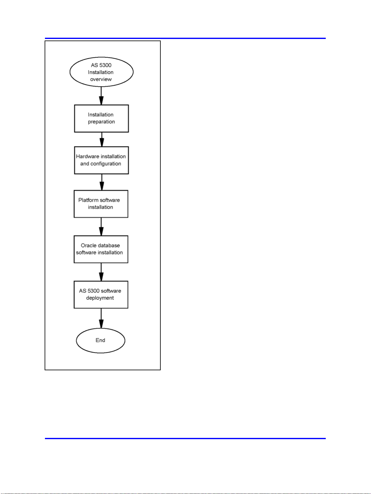
Installation overview
This chapter describes the steps required to install AS 5300 servers and
the approximate time needed to complete each step.
Installation overview procedures
This diagram shows the steps required to complete AS 5300 installation.
11
Copyright © 2007-2008 Nortel Networks
.
Application Server 5300
Nortel AS 5300 Installation
NN42040-300 01.04
4 November 2008
Page 12
12 Installation overview
Installation overview navigation
•
"Installation times" (page 12)
Installation times
This section describes the approximate time required for each major step
of the AS 5300 installation process.
Application Server 5300
Nortel AS 5300 Installation
NN42040-300 01.04
Copyright © 2007-2008 Nortel Networks
.
4 November 2008
Page 13

Installation times 13
Table 1
Installation preparation
Installation step Approximate time required to complete
Unpacking the hardware 10 minutes
Table 2
Hardware installation and configuration
Installation step Approximate time required to complete
Mounting the hardware 20 minutes
Connecting the hardware 20 minutes
Resetting the planar BIOS 5 minutes
Resetting the ServeRAID BIOS 5 minutes
Configuring the RSA-II card 10 minutes
Configuring the planar BIOS 5 minutes
Configuring the ServeRAID BIOS 15 minutes
Table 3
Platform software installation
Installation step Approximate time required to complete
Starting the Linux operating system installation 1–2 minutes
Configuring the networking, serial console
10 minutes
redirection, and time zone settings
Configuring the NTP, Syslog, and Audit
2–3 minutes
Daemon settings
Configuring the BIOS hardware clock 1–2 minutes
Configuring accounts and passwords 5–10 minutes
Installing Linux updates 15 minutes
Table 4
Oracle database software installation
Installation step Approximate time required to complete
Installing Oracle 35 minutes (Primary and Secondary performed
in parallel)
Installing Oracle updates 15 minutes
Table 5
AS 5300 software deployment
Installation step Approximate time required to complete
Downloading the MCP software 5 minutes
Preparing the initial load for deployment 5 minutes
Application Server 5300
Nortel AS 5300 Installation
NN42040-300 01.04
Copyright © 2007-2008 Nortel Networks
4 November 2008
.
Page 14

14 Installation overview
Table 5
AS 5300 software deployment (cont’d.)
Installation step Approximate time required to complete
Deploying the initial software load 45–50 minutes
Updating the licensekey 10 minutes
Copyright © 2007-2008 Nortel Networks
.
Application Server 5300
Nortel AS 5300 Installation
NN42040-300 01.04
4 November 2008
Page 15

.
Installation preparation
This section describes the preparation of materials and hardware required
for installing the AS 5300 server.
Navigation
•
"Unpack the materials" (page 15)
• "Customer-specific information" (page 15)
Unpack the materials
Before installing the server, verify that all of the necessary components
required for installation are on-site. You require the following components:
•
IBM x3550 core server
• CD/DVD set containing firmware updates
• AS 5300 Release 1.0 SIP Core New System Software Package,
consisting of CD/DVD-ROMs containing the Linux operating system
and Oracle database installation software, product documentation, and
the MCP core load software
15
• USB keyboard, mouse, and monitor, or a keyboard, video and mouse
(KVM) unit
The number of servers and software packages received varies depending
on the type of system configuration you install (simplex or redundant).
In addition, ensure there are an adequate number of properly grounded
electrical outlets for the server, monitor, and other devices.
For more information about server hardware, including the installation of
hot-swap components and other devices, see IBM System x3550 Type
7978 User Guide.
Customer-specific information
Ensure that the Installation Planning Sheet lists all server names and IP
addresses. Complete an Installation Planning Sheet for each individual
server being installed.
Application Server 5300
Nortel AS 5300 Installation
NN42040-300 01.04
Copyright © 2007-2008 Nortel Networks
4 November 2008
.
Page 16

16 Installation preparation
This sheet is located in the chapter titled "Installation Planning sheet"
(page 17).
Copyright © 2007-2008 Nortel Networks
.
Application Server 5300
Nortel AS 5300 Installation
NN42040-300 01.04
4 November 2008
Page 17

.
Installation Planning sheet
This section contains the Installation Planning Sheet.
Use the Installation Planning sheet to compile the information required for
installing an AS 5300 server. Print and complete an Installation Planning
sheet for each server being installed.
Installation Planning Sheet (Individual Server)
Applies To
Item
19" Data Frame All
Location Within 19" Data Frame All
Switch Port Hosting eth0 Net I/F All
Server Type Example Value Actual Value
Physical Installation
Site-Dependent
Labeling
Site-Dependent
Labeling
Equipment-specific
Labeling
17
Equipment-specific
Switch Port Hosting eth1 Net I/F All
Switch Port Hosting RSA-II Net I/F All
Terminal Server Port Hosting
Serial Console RS-232 Cable (if
applicable) All
KVM Port Hosting Server Video and
Keyboard (if applicable) All
Power Supply 1 Cabling All
Power Supply 2 Cabling All
Networking Information
Server Host Name All ems1host
Service VLAN ID All 170
Application Server 5300
Nortel AS 5300 Installation
NN42040-300 01.04
4 November 2008
Copyright © 2007-2008 Nortel Networks
Labeling
Equipment-specific
Labeling
Equipment-specific
Labeling
Equipment-specific
Labeling
Equipment-specific
Labeling
Equipment-specific
Labeling
.
Page 18

18 Installation Planning sheet
Service VLAN Machine Logical
Address All 10.10.0.5
Service VLAN Default Gateway All 10.10.0.1
Service VLAN Network Mask All 255.255.0.0
Maintenance VLAN ID All 1265
Maintenance VLAN Machine Logical
Address All 192.168.2.5
Maintenance VLAN Default
Gateway All 192.168.2.1
Maintenance VLAN Network Mask All 255.255.255.0
RSA-II Card IP Address All 192.168.3.5
RSA-II Card Default Gateway All 192.168.3.1
RSA-II Card Network Mask All 255.255.255.0
Remote Platform Backup Retrieval (Server Restore)
Remote Server IP Address All 10.12.1.5
Remote Server User ID All bkupstor
Remote Server User Password All n/a
Remote server backup directory All ./platform_backups
mcpPlatform.ems1
host. 2007_10_29.
Backup file name All
11_32_09.tar
Miscellaneous
Serial Console Port Baud Rate All 9600
External NTP Time Server (Clock
10.11.130.30,
Source) IP Addresses for runtime
system EMS1, EMS2 10.11.131.31
Primary NTP Clock Source (EMS1)
IP Address NES (all) 10.10.0.5
Secondary NTP Clock Source
(EMS2) IP Address NES (all) 10.10.0.6
Timezone All US / Central
Syslog server (if required) All 10.12.1.6
External NTP Time Server (Clock
All
Source) for RSA-II card (optional) 192.168.3.250
Passwords
Preconfigured Account Initial Passwords, if used (not required for restore reinstalls)
ntappadm All QWEpoi43@!
ntsysadm All QWEpoi43@!
Application Server 5300
Nortel AS 5300 Installation
NN42040-300 01.04
Copyright © 2007-2008 Nortel Networks
4 November 2008
.
Page 19

Customer-specific information 19
ntsecadm All QWEpoi43@!
ntbackup All QWEpoi43@!
ntdbadm All QWEpoi43@!
IAO Single Account Information, if used (not required for restore reinstalls)
IAO User Id All iaouser
IAO Password All QWEpoi43@!
GRUB Bootloader All QWEpoi12#$
System Account Initial passwords (required for all installs)
root All QWEpoi12#$
ntossadm All QWEpoi12#$
nortelrps All QWEpoi12#$
Copyright © 2007-2008 Nortel Networks
.
Application Server 5300
Nortel AS 5300 Installation
NN42040-300 01.04
4 November 2008
Page 20

20 Installation Planning sheet
Copyright © 2007-2008 Nortel Networks
.
Application Server 5300
Nortel AS 5300 Installation
NN42040-300 01.04
4 November 2008
Page 21

.
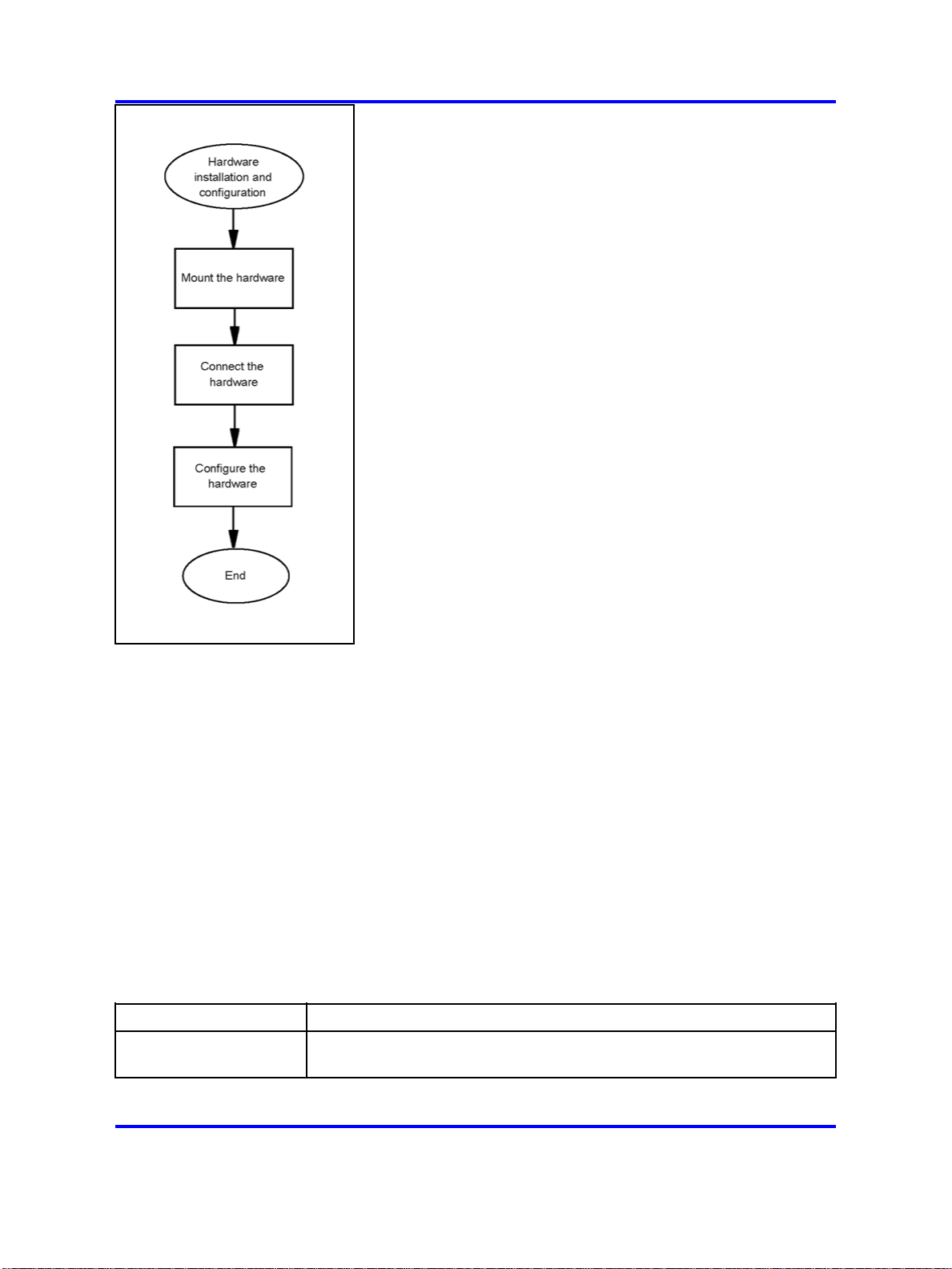
Hardware installation and
configuration
This section describes the procedures for installing and configuring the
AS 5300 server hardware.
Prerequisites
For more information about basic hardware installation, see IBM x3550
Installation Guide.
Hardware installation and configuration procedures
This work flow diagram shows the steps required to install and configure
the AS 5300 hardware.
21
Copyright © 2007-2008 Nortel Networks
.
Application Server 5300
Nortel AS 5300 Installation
NN42040-300 01.04
4 November 2008
Page 22
22 Hardware installation and configuration
Hardware installation and configuration navigation
•
"Hardware overview" (page 22)
• "Mount the hardware" (page 23)
• "Connect the hardware" (page 24)
• "Networking overview" (page 27)
• "Hardware configuration" (page 30)
Hardware overview
The AS 5300 product uses the IBM x3550 server for its core server
platforms. For more information about the hardware characteristics of the
IBM x3550 server, see Table 6 "IBM x3550 hardware characteristics"
(page 22).
Table 6
IBM x3550 hardware characteristics
Item Description
Form factor Height: 1U (1.69 inches), width: 17.3 inches, depth: 28 inches, weight:
34 lb, rack mount
Copyright © 2007-2008 Nortel Networks
.
Application Server 5300
Nortel AS 5300 Installation
NN42040-300 01.04
4 November 2008
Page 23

Mount the hardware 23
Table 6
IBM x3550 hardware characteristics (cont’d.)
Item Description
Server identification x3550, Model 7978 AC1
CPU 2 x Quad-Core Intel Xeon processor E5420, 2.5GHz, 12 MB L2 cache,
1333MHz FSB, 80w
Memory 8 GB PC2-5300 CL5 ECC DDR2 Chipkill FB DIMM 667MHz
Disk 2 x 73 GB 3.5-inch SAS, 15000 RPM, hot swap; RAID-1 mirrored using
IBM ServeRAID 8k-l SAS controller (hardware RAID-1)
AC power 2 x 670W A/C Power Supply (redundant, hot-swap); 2.8m, 100-240V,
C13 to IEC 320-C14 (WW) rack power cable
DC power 2 x 670W D/C Power Supply (redundant; hot swap); 2.8m, 100-240V,
C13 to IEC 320-C14 (WW) rack power cable
Remote management Remote Supervisor Adapter II (RSA-II) Slimline with external RJ-45
Ethernet port (internal PCI card)
Optical drive DVD/CD-RW
Cooling Two fans per CPU, one fan per power supply
Networking 2 x 10/100/1000 Mbps
Serial COM1, DB-9
Rail kit Pizarro (Nortel-specified)
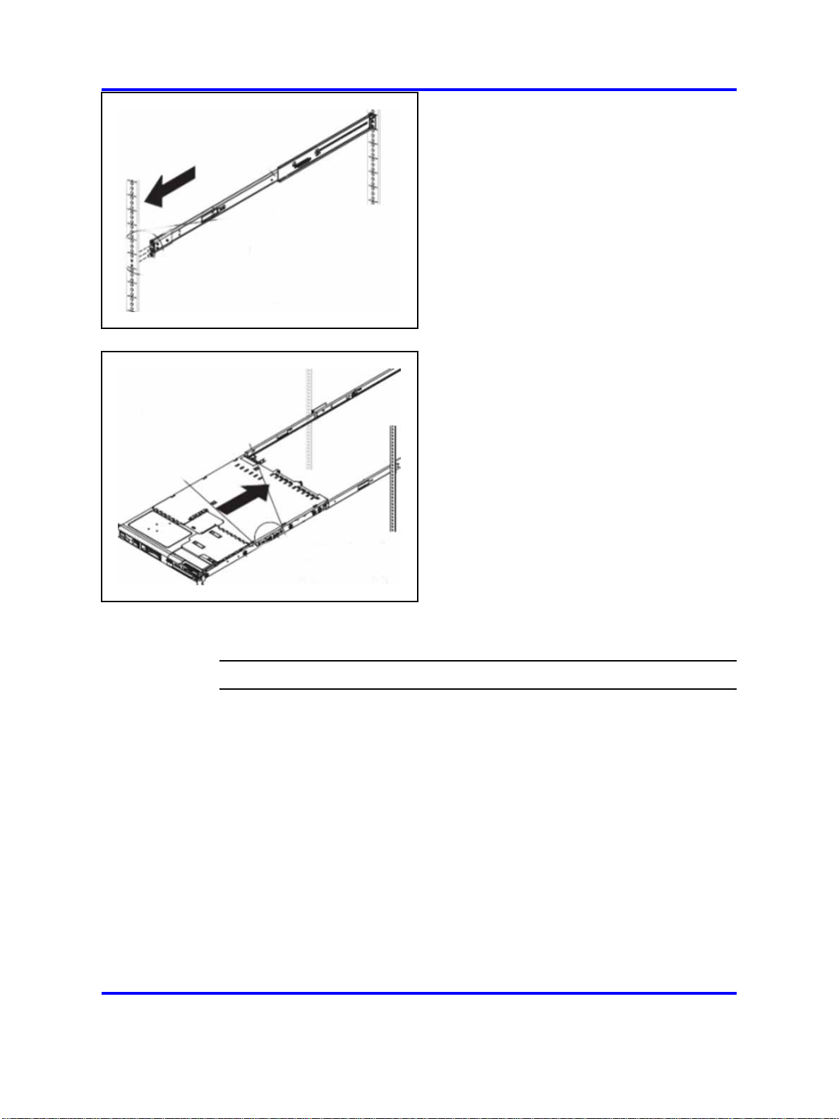
Mount the hardware
The AS 5300 server requires the Pizzaro rail kit for rack-mount
installations.
Mounting the server
Use this procedure to mount the physical server into a server rack.
Prerequisites
• You require a Pizzaro rail kit for each IBM x3550 server being installed.
Procedure Steps
Step Action
1 Adjust the rail kit to fit in the frame. To properly support the
server, each rail must be mounted to the outside of the front and
rear of the frame.
2 Adjust the left and right rails by sliding the rear mounting bracket
to fit the frame.
Copyright © 2007-2008 Nortel Networks
.
Application Server 5300
Nortel AS 5300 Installation
NN42040-300 01.04
4 November 2008
Page 24
24 Hardware installation and configuration
3
4
5 Bolt the front of the server to the front of the rail kit.
Securely install the rail kit and then slide the server into place.
Ensure the server is supported in the rear by the rail kit.
Connect the hardware
For more information about the front and rear panels of the AS 5300
server, see Figure 1 "Front panel of the AS 5300 server" (page 25) and
Figure 2 "Rear panel of the AS 5300 server" (page 25) .
--End--
Copyright © 2007-2008 Nortel Networks
.
Application Server 5300
Nortel AS 5300 Installation
NN42040-300 01.04
4 November 2008
Page 25
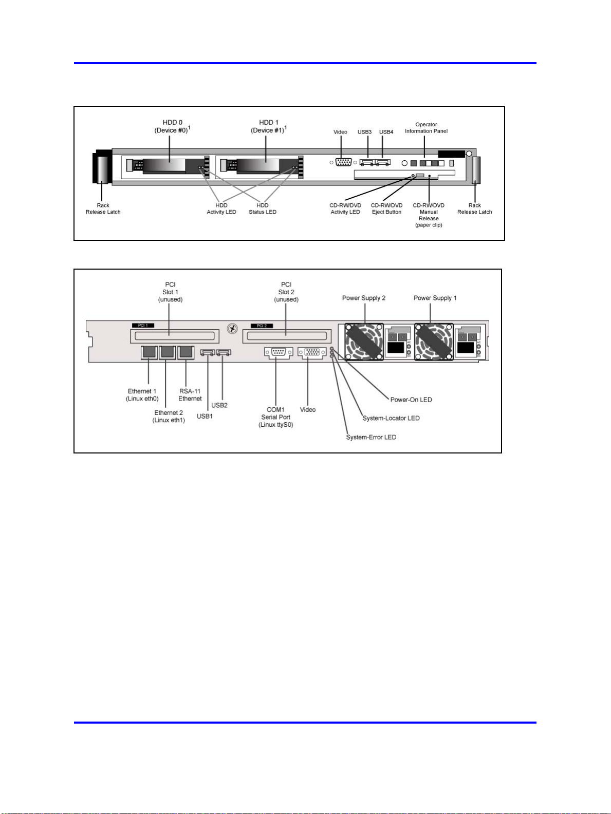
Figure 1
Front panel of the AS 5300 server
Figure 2
Rear panel of the AS 5300 server
Connect the hardware 25
Ethernet 1 and Ethernet 2 are the main Network Interface Card (NIC) ports
that carry traffic for the primary application of the server. These ports are
configured to run in redundant mode with one port active and the other on
standby, so connect them to a redundant host switch.
The Remote Supervisor Adaptor (RSA-II) is a PCI card that provides
an Ethernet interface for remote system management of the server. It
includes an embedded Web server. When the server is secured, the
RSA-II card Ethernet port provides HTTPS/SSH access to the RSA-II card
for remote management of the server. This includes access to controls
to manage the power state of the server and inspect physical attributes,
as well as to gain encrypted remote access to the physical console of the
server. This port is typically cabled to a port in a maintenance network,
separate from the network used for the primary application of the server.
The COM1 serial port provides serial console access using an industry
standard RS-232 serial cable and is typically connected to either a terminal
server such as the MRV Models LX-40XX or it can be attached to a serial
port on another computer using a null modem cable. If the COM1 serial
Copyright © 2007-2008 Nortel Networks
Application Server 5300
Nortel AS 5300 Installation
NN42040-300 01.04
4 November 2008
.
Page 26

26 Hardware installation and configuration
port is attached to another computer, such as a Windows-based computer,
a program such as HyperTerminal can be used to establish a login session
over the serial connection. COM1 is the only serial port supported for AS
5300 systems.
For more information about the serial port pinout for COM1, see Table 7
"COM 1 serial port pinout" (page 26).
Table 7
COM 1 serial port pinout
PIN number Assignment
Name Description
1
2
3
4
5
6
7
8
9
DCD Data Carrier Detect
RXD Received Data
TXD Transmitted Data
DTR Data Terminal Ready
GRND Common Ground
DSR Data Set Ready
RTS Request To Send
CTS Clear To Send
RI Ring Indicator
During the software platform installation procedure, you have the option
of configuring the COM1 serial port (in Linux, this is referred to as ttyS0)
for console login during system runtime. The configured serial port has
the following characteristics:
• 7-bit characters with even, odd, none, or space parity, and 8-bit
characters with no parity are supported
• Only COM1 (ttyS0) is supported
• Terminal emulation is VT100
• The user has the option of configuring either a 9 600 or 19 200 baud
rate
Connect a physical monitor or a KVM switch to the video port. This
provides the physical KVM console. Nortel does not provide a KVM for
use with this product.
Connect a USB keyboard, or a KVM switch, to one of the USB ports to
provide a physical KVM console. A USB keyboard connected through
a KVM switch can sometimes become unresponsive while switching
consoles at the KVM keyboard. If this occurs, typing CTRL+Q toggles the
flow control signals to restore keyboard communications with the server.
Copyright © 2007-2008 Nortel Networks
.
Application Server 5300
Nortel AS 5300 Installation
NN42040-300 01.04
4 November 2008
Page 27

Attach the two redundant AC (Alternating Current) power modules to
redundant AC power sources, as required by industry standards.
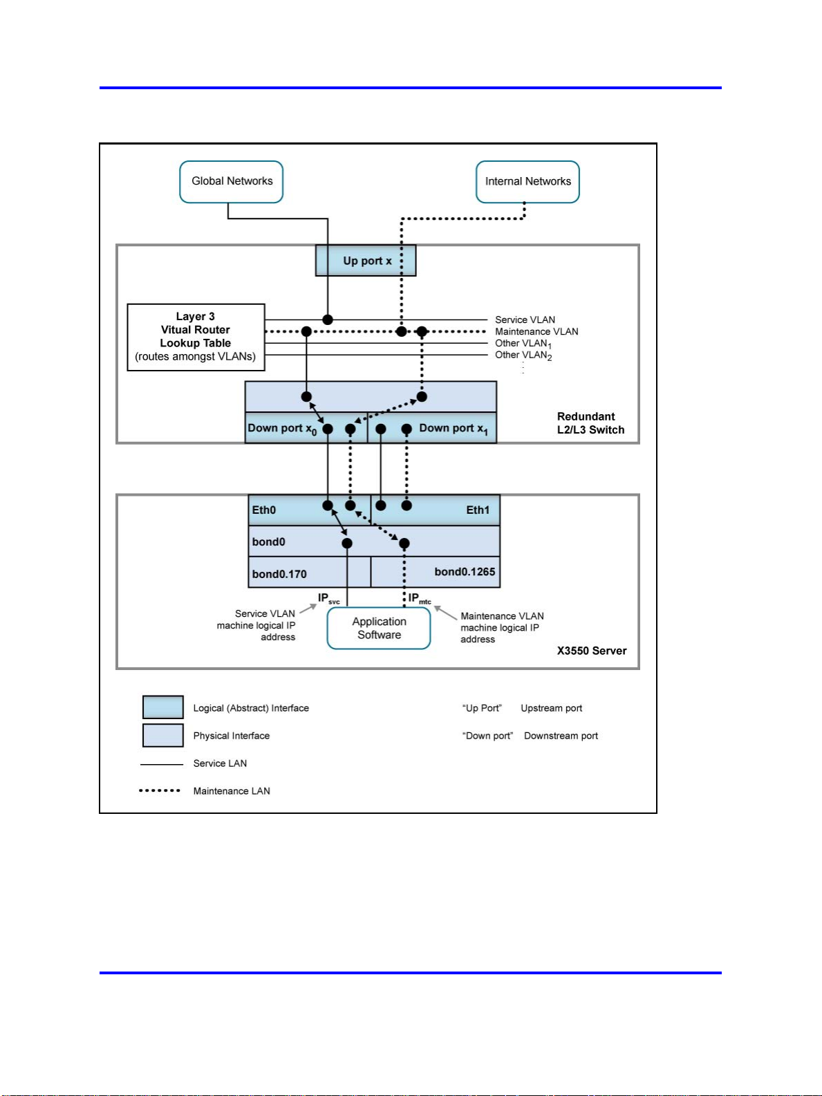
Networking overview
The standard networking configuration for the AS 5300 system is a
Dual-VLAN configuration. In this type of networking configuration, the
server is connected to two different VLANs (or networks):
•
Service network
• Maintenance network
The server has a machine logical address for each network and frames
entering and leaving the server are tagged with the appropriate network
identifier. The hosting network equipment must support VLANs and not
perform VLAN tag processing on behalf of the server.
In a typical Dual-VLAN configuration, the majority of network traffic
traverses the Service network. This includes signaling, Operations,
Administration, Maintenance, Provisioning (OAMP), and software
heartbeating. The Maintenance network is used for a few specific
functions, including the extraction of Operations Support Systems (OSS)
feeds by northbound Network Management System (NMS).
Networking overview 27
For more information about a typical Dual-VLAN networking configuration,
see Figure 3 "Typical Dual-VLAN configuration" (page 28) .
Copyright © 2007-2008 Nortel Networks
.
Application Server 5300
Nortel AS 5300 Installation
NN42040-300 01.04
4 November 2008
Page 28
28 Hardware installation and configuration
Figure 3
Typical Dual-VLAN configuration
The server maintains the use of the kernel channel bonding module to
implement the bond0 logical interface (enslaving eth0 and eth1 in active
or standby mode). A second kernel module, the 8021q VLAN module,
implements VLAN capabilities on top of the logical bond0 interface. This
module implements one logical interface for each VLAN, where each is
logically placed on top of the bond0 interface.
Copyright © 2007-2008 Nortel Networks
.
Application Server 5300
Nortel AS 5300 Installation
NN42040-300 01.04
4 November 2008
Page 29

Networking overview 29
VLAN interfaces are named according to the following syntax:
<hosting_interface>.<vlan_id>
The AS 5300 server defines the VLAN interfaces to be hosted by the
logical bond0 interface. Figure 3 "Typical Dual-VLAN configuration" (page
28) shows a VLAN interface named bond0.170, which belongs to the
VLAN with ID 170, and the VLAN interface bond0.1265, which belongs
to the VLAN with ID 1265. It is on these logical VLAN interfaces that the
machine logical IP addresses of the Service and Maintenance VLANs are
configured (one for each VLAN). Software applications are concerned only
with these logical VLAN interfaces.
Nortel does not recommend Zero-VLAN configurations for standard AS
5300 configurations, but Zero-VLAN configurations can be implemented
in non-standard configurations, such as in a lab or testing environment.
Servers in a Zero-VLAN configuration have no knowledge of VLAN ID
tagging.
Consult the Information Planning Sheet for details about network settings.
Network Time Protocol
Two Element Manager servers (EMS) serve as Network Time Protocol
(NTP) clock sources for the Network Element servers (NES) in the AS
5300 system. You can configure the two EMS servers to receive their
clock information from their internal system clocks or from external
sources. It is recommended that you configure the servers to receive
their clock information from external sources so that all of the servers in
the system are synchronized with each other as well as with global clock
sources.
If you configure the EMS servers to use their internal clocks as the
system time source, the system is synchronized internally but has no
synchronization with global clock sources.
In addition to being configured to use internal or external clock sources,
the EMS servers maintain time synchronization with each other.
The NTP protocol is not secure. You can secure NTP traffic using
symmetric keys for server authentication or by configuring the IPSec mesh.
Symmetric keys are stored in a key file on both the client and clock source
server. Modify the Network Time Protocol configuration file to specify
which key in the key file to use. In 2-server or 4-server configurations,
symmetric key usage is only configured on the servers hosting the System
Managers. In the 4-server configuration, the non-System Manager servers
Copyright © 2007-2008 Nortel Networks
.
Application Server 5300
Nortel AS 5300 Installation
NN42040-300 01.04
4 November 2008
Page 30

30 Hardware installation and configuration
can have their time source server configured to use the System Managers,
as IPsec is already configured between System Manager servers and
non-System Manager servers.
For more information about security for Network Time Protocol, see Nortel
AS 5300 Security (NN42040-601).
Hardware configuration
This section contains information and procedures for configuring the Basic
Input Output System (BIOS) and RSA-II card on the AS 5300 server.
Prerequisites
• You require a USB keyboard, mouse, and monitor, or KVM unit.
Hardware configuration procedures
This work flow shows the sequence of procedures you perform to
configure the BIOS on an AS 5300 server.
Copyright © 2007-2008 Nortel Networks
.
Application Server 5300
Nortel AS 5300 Installation
NN42040-300 01.04
4 November 2008
Page 31

Hardware configuration 31
Hardware configuration navigation
• "Resetting the planar BIOS and RSA-II card to factory defaults" (page
32)
• "Resetting the ServeRAID BIOS to factory defaults" (page 33)
• "Configuring the RSA-II card" (page 35)
Copyright © 2007-2008 Nortel Networks
.
Application Server 5300
Nortel AS 5300 Installation
NN42040-300 01.04
4 November 2008
Page 32

32 Hardware installation and configuration
• "Configuring the planar BIOS" (page 36)
• "Configuring the ServeRAID BIOS" (page 38)
Resetting the planar BIOS and RSA-II card to factory defaults
When you install a new AS 5300 server (new installation or replacement
of a failed server), you must configure the BIOS settings of the server to
the standard product supported configuration. This involves the resetting
of the BIOS settings to factory defaults followed by the application of
product-specific configuration settings. Restoring of factory defaults for
any of the BIOS components does not have an impact on the others. They
need to be restored independently.
Use this procedure to reset the planar BIOS and RSA-II card to the factory
default settings.
Attention: When you reset the RSA-II card, all existing network
connections to the RSA-II Ethernet interface are disconnected and no
further connections can be made until network settings are reconfigured.
Procedure Steps
Step Action
1
2 From the Configuration/Setup Utility menu, select the System
From the physical KVM console, reboot the AS 5300 server and
press F1 at the IBM splash screen when prompted to access the
planar BIOS configuration utility.
Summary option and confirm "8192 MB" (8 GB) for Installed
Memory. If it is not, contact your next level of support before
proceeding.
Attention: If the system summary does not show 8192 MB,
confirm the order code matches the serial number for the server
against the shipping packing list (or the box the server was
delivered in).
Order code XYSG9US: 8 GB of RAM AS5300 Linux Core
Servers
Order code XYSGAUS: 4 GB of RAM MAS Platform Servers
It also possible that the server may have the correct order code
Copyright © 2007-2008 Nortel Networks
.
Application Server 5300
Nortel AS 5300 Installation
NN42040-300 01.04
4 November 2008
Page 33

with the correct memory configuration but not recognized by the
system. If this happens, contact your next level of support before
proceeding.
3 Select Advanced Setup.
Hardware configuration 33
4
5 Select Restore RSA II Defaults.
Select RSA-II Settings.
Network settings for the RSA-II card are restored to factory
defaults. Any existing network connections to the RSA-II
Ethernet interface are disconnected and no further connections
can be made until network settings are reconfigured.
When the reset to factory defaults is complete, the following
message appears:
RSA II Defaults Loaded!
If data had been previously configured for the RSA-II card, that
data appears.
6 Press Enter.
7 Press Esc until the top level menu of the planar BIOS setup
utility appears.
8
Select Load Default Settings.
The following message appears:
Current settings will be changed to their default
settings - Press Enter to continue.
9
Press Enter.
The planar BIOS is restored to the factory defaults.
10
11
Select Exit Setup.
Select Yes, save and exit the Setup Utility and press Enter.
The server reboots.
Resetting the ServeRAID BIOS to factory defaults
Use this procedure to reset the ServeRAID BIOS to the factory default
settings.
Copyright © 2007-2008 Nortel Networks
--End--
Application Server 5300
Nortel AS 5300 Installation
NN42040-300 01.04
4 November 2008
.
Page 34

34 Hardware installation and configuration
WARNING
The resetting of the ServeRAID BIOS to factory defaults
includes the destruction of all currently defined RAID arrays.
This results in the deletion of all data on the disk drives and
requires reinstallation of all server software.
Procedure Steps
Step Action
1 Reboot the system.
The system displays the following message:
Press CTRL-A for IBM ServeRAID Configuration
Utility
2
Press CTRL+A .
The IBM ServerRAID Configuration Utility screen appears.
3
Delete any existing arrays (if configured during previous
installations) by doing the following:
• Select Array Configuration Utility.
• Press M to select Manage Arrays.
— If the message No Arrays present appears, there are
no arrays configured. Press Esc to return to the top-level
menu and continue with step 4.
— Otherwise, the List of Arrays appears.
• Highlight the array and press Del to delete it.
• Select Delete.The system displays the following prompt:
WARNING: Deleting will erase all data from the
array. Do you still want to continue? (Yes/No)
• Press Y to continue.
• Press Esc twice to return to the top-level menu.
4 Select SerialSelect Utility.
5 Select Controller Configuration.
6 Press F6 to reset to factory defaults.
7 Select Yes to reset the ServeRAID BIOS to default.
8 Press Esc to return to the previous menu.
The system displays the following prompt:
Save changes made? (Yes/No)
9 Select Yes to save changes.
10 Select PHY Configuration.
Copyright © 2007-2008 Nortel Networks
.
Application Server 5300
Nortel AS 5300 Installation
NN42040-300 01.04
4 November 2008
Page 35

Hardware configuration 35
11
12
13 Press Esc until you return to the IBM ServerRAID Configuration
Press F6 to reset to factory defaults.
Select Yes to reset the defaults.
Utility screen.
14 Select Yes to save changes made.
15
16
Press Esc to exit ServeRAID setup.
Select Yes to save the changes and exit.
Configuring the RSA-II card
Use this procedure to configure nonsecure access for the RSA-II card.
Prerequisites
• The planar and ServeRAID BIOS have both been reset to the factory
default settings.
• This procedure describes only the nonsecure configuration of the
RSA-II card. For more information about configuring security for the
RSA-II card, see Nortel AS 5300 Security (NN42040-601).
--End--
Procedure Steps
Step Action
1
2 From the planar BIOS setup utility screen, select Advanced
3 Select RSA-II Settings.
4 Highlight DHCP Control and use the left and right arrow keys
5 Highlight Static IP Address.
6 Press the backspace key until the IP address field is empty, and
7 Highlight Subnet Mask and enter the subnet mask of the
8 Highlight Gateway and enter the default gateway of the Ethernet
From the physical KVM console, reboot the AS 5300 server and
press F1 to access the planar BIOS configuration utility.
Setup.
to select Use Static IP.
type the IP address of the RSA-II card. Use backspace key to
correct any data entry errors.
Ethernet interface of the RSA-II card (using the same method
as for entering the IP address).
interface of the RSA-II card (using same method as for entering
the IP address).
Copyright © 2007-2008 Nortel Networks
.
Application Server 5300
Nortel AS 5300 Installation
NN42040-300 01.04
4 November 2008
Page 36

36 Hardware installation and configuration
9
Highlight OS USB Selection and use the left and right arrow
keys to select Linux OS.
10 Select Save Values and Reboot RSA II.
11 When prompted, press Enter to confirm.
The BIOS is unresponsive for approximately 20 seconds while
the RSA-II card reboots. When the card has finished rebooting,
the following message appears:
RSA-II Settings Saved
12
Press Enter.
Ignore the prompt to reset the RSA-II card.
13 Press Esc until the Configuration/Setup Utility screen is
reached.
14 Select Exit Setup.
15
Select Yes to save and exit the Setup Utility.
The RSA-II card is now configured for non-secure access using
supported IP-based protocols, such as HTTP and TELNET. You
can now reconnect the Ethernet cable.
For more information about configuring security for the RSA-II
card, see Nortel AS 5300 Security (NN42040-601).
Configuring the planar BIOS
Use this procedure to configure the planar BIOS.
WARNING
There is an option to configure an Administrative password
during BIOS configuration. The configuration of BIOS
passwords is not recommended; however, local security policies
might require that BIOS passwords be used. Use extreme
caution if configuring BIOS Administrative passwords. If the
password is lost or forgotten, it cannot be recovered, and the
motherboard of the server must be replaced. See Nortel AS
5300 Security (NN42040-601).
WARNING
There is an option to configure a Power-on password during
BIOS configuration. Do not configure Power-on passwords as
this could possibly interfere with the restarting of servers.
Prerequisites
• The planar BIOS has been reset to the factory default settings.
--End--
Copyright © 2007-2008 Nortel Networks
.
Application Server 5300
Nortel AS 5300 Installation
NN42040-300 01.04
4 November 2008
Page 37

Procedure Steps
Step Action
Hardware configuration 37
1
Reboot the server and press F1 to access the planar BIOS
configuration utility.
The following steps ensure that the Power-on password is not
configured by deleting all existing Power-on passwords.
2 Select System Security > Power-on Password.
3
Highlight Delete Power-on Password and press Enter.
The following message appears:
Any existing power-on password will be deleted.
4
5
6 Select Start Options.
7
8
9
10
11 Highlight Second Startup Device and choose Hard Disk 0.
12 Highlight Third Startup Device and choose Disabled.
Press Enter to confirm.
Press Esc to cancel and return to the previous menu.
Highlight Planar Ethernet PXE/DHCPand choose Disabled.
Highlight USB Disk and choose Disabled.
Select Startup Sequence Options.
Highlight First Startup Device and choose CD ROM.
13
14
15 Press Esc twice to return to the top-level menu.
16
17
18 Highlight Serial Port B and choose Disabled.
19 Press Esc to return to top level menu.
20 Select Date and Time.
21 Highlight Time and enter the current local time.
22
23 Press Esc to return to top level menu.
24 Select Save Settings and press Enter when the confirmation
Highlight Fourth Startup Device and choose Disabled.
Highlight Wake On LAN and choose Disabled.
Select Devices and I/O Ports.
Highlight Serial Port A and choose Port 3F8, IRQ 4.
Highlight Date and enter the current local date.
message displays.
Copyright © 2007-2008 Nortel Networks
Application Server 5300
Nortel AS 5300 Installation
NN42040-300 01.04
4 November 2008
.
Page 38

38 Hardware installation and configuration
25
Select Exit Setup and select Yes when prompted for
confirmation.
Configuring the ServeRAID BIOS
Use this procedure to configure the ServeRAID BIOS.
Prerequisites
•
The ServeRAID BIOS has been reset to the factory default settings.
Procedure Steps
Step Action
1
2
Reboot the server.
The server restarts and the following message displays:
Press CTRL-A for IBM ServeRAID Configuration
Utility
Press CTRL+A.
The IBM ServerRAID Configuration Utility screen appears.
--End--
3
4
5
6 Choose SATA Off, SAS Off.
7 Press Esc to return to the previous menu.
8
9 Press Esc to return to the ServeRAID Configuration Utility
Select SerialSelect Utility.
Select Controller Configuration.
Select Drives Write Cache.
Select Yes to the Save Changes Made prompt.
menu.
10
11 Press C to create an array.
Select Array Configuration Utility.
The Select drives to create Array window appears.
The Selected Drives list should be empty.
12 Highlight the first disk and press Ins.
The selected disk is added to the right window and the second
drive is now highlighted.
13 Press Ins to insert the second drive into the list.
The second drive is included in the Selected Drives list.
14 Press Enter.
Copyright © 2007-2008 Nortel Networks
.
Application Server 5300
Nortel AS 5300 Installation
NN42040-300 01.04
4 November 2008
Page 39

Hardware configuration 39
The Array Properties window appears.
15 In the Array Type sub-window, select RAID 1(Mirror).
This cursor moves to Array Label.
16
For Array Label, enter mcp-raid1 and press Enter.
The cursor moves to the Array Size line.
17 Press Enter to confirm the disk size (do not modify it), then press
Enter to accept the size unit value of GB.
The cursor moves to Create RAID via and highlights Quick Init.
18
19
Press Enter to select Quick Init.
Press Enter to select Done.
The Array Configuration screen appears.
20 Press M to manage arrays.
The List of Arrays appears with the mcp-raid1 array listed.
21 Press Esc twice to return to the root level menu.
22
Press Esc to exit the ServeRAID configuration utility and select
Yes on the confirmation window.
--End--
Copyright © 2007-2008 Nortel Networks
.
Application Server 5300
Nortel AS 5300 Installation
NN42040-300 01.04
4 November 2008
Page 40

40 Hardware installation and configuration
Copyright © 2007-2008 Nortel Networks
.
Application Server 5300
Nortel AS 5300 Installation
NN42040-300 01.04
4 November 2008
Page 41

.
Platform software installation
This section describes how to install the AS 5300 platform software.
The platform software consists of the underlying Linux kernel, which is
the base-level software packages required for a Linux-based operating
system, and the customized Nortel software, scripts, and server
configurations that prepare the system for an AS 5300 environment. SIP
core AS 5300 servers require the platform software installation. Use these
procedures for the configuration of new servers and the reinstallation of the
platform software due to server recovery.
Many of the prompts displayed during installation have default values
contained within square brackets ([ ]). Pressing the Enter key indicates
acceptance of the default values.
The Linux installer presents a series of questions to the user. At certain
points during the question-and-answer process, the user is presented
with a summary of the choices made. The user then has the option of
correcting errors made during the earlier steps. Previous answers are
provided as defaults, allowing the user to quickly accept them as correct
values.
41
The Core Linux 11.0.x CD-ROM that shipped with your product contains
the Linux installation files.
Perform the installation procedures using the physical KVM console or the
RSA-II remote control.
Throughout these procedures, the term installer refers to the Linux
installation script, and not the person performing the installation.
Platform software installation procedures
This work flow shows the sequence of steps required to install the platform
software.
Application Server 5300
Nortel AS 5300 Installation
NN42040-300 01.04
Copyright © 2007-2008 Nortel Networks
4 November 2008
.
Page 42

42 Platform software installation
Copyright © 2007-2008 Nortel Networks
.
Application Server 5300
Nortel AS 5300 Installation
NN42040-300 01.04
4 November 2008
Page 43

Hardware configuration 43
Platform software installation navigation
•
"Starting the Linux operating system installation" (page 44)
• "Configuring the networking, serial console redirection, and time zone
settings" (page 45)
• "Configuring the NTP, Syslog, and Audit Daemon settings" (page 47)
• "Configuring the BIOS hardware clock" (page 50)
• "Configuring accounts and passwords" (page 51)
• "Reinstalling platform software" (page 55)
Application Server 5300
Nortel AS 5300 Installation
NN42040-300 01.04
Copyright © 2007-2008 Nortel Networks
.
4 November 2008
Page 44

44 Platform software installation
Starting the Linux operating system installation
Use this procedure to initiate the Linux operating system installation
process. This phase of the installation process accomplishes the following
objectives:
•
displays the licensing information
•
gathers the hardware and system information
• presents the option to restore a remote platform backup file
Prerequisites
• Core Linux 11.0.x installation CD
• Core Linux Maintenance Release patch CDs (if applicable)
•
CD-ROM drive is selected as first priority boot device in the system
BIOS (normally set during initial BIOS configuration)
• Server backup file on a remote server (if applicable)
Procedure Steps
Step Action
1
2
3 The installer prompts for acceptance of the licensing agreement.
4 The installer scans for basic hardware configuration to determine
Load the Core Linux 11.0.x installation CD in the CD-ROM drive
and reboot the server.
The installation welcome screen appears.
At the boot prompt, type install-kvm and then press Enter.
The Linux boot kernel (the version of the kernel that runs during
the installation procedure) loads and the installation program
starts.
Choose one of the following responses:
Reply Y if you have previously reviewed the licensing agreement
information and agree to it.
OR
Reply N (default) to review the licensing agreement information.
The MCP Software Licensing menu appears. You can choose to
review the Licensing Overview, the Summary of Open Source
RPMs and Licenses, or Exit.
After you have reviewed and accepted the licensing agreement
information, installation continues. If you do not accept the
licensing agreement, installation stops and the server reboots.
and verify the system environment, and displays the list of
detected disk devices with their storage sizes.
Copyright © 2007-2008 Nortel Networks
.
Application Server 5300
Nortel AS 5300 Installation
NN42040-300 01.04
4 November 2008
Page 45

Configuring the networking, serial console redirection, and time zone settings 45
If the hardware verification fails, an error message displays, the
installation aborts, and the server reboots.
Otherwise, the following message appears:
Press ENTER to Continue
5 Press Enter.
The system displays the following message:
Would you like to retrieve a platform backup file
from a remote server?
6 If you are restoring a platform backup file, reply Y and proceed to
"Reinstalling platform software" (page 55).
7
8
Press Enter to accept the default response of N.
The system configuration screen appears.
Press Enter to continue installation.
--End--
Configuring the networking, serial console redirection, and time
zone settings
This phase of the Linux operating system installation includes the
configuration of the following items:
• networking parameters for Dual-VLAN
•
serial console redirection
•
region and time zone selection
Prerequisites
•
You have completed the steps described in "Starting the Linux
operating system installation" (page 44).
Procedure Steps
Step Action
1 The system displays the following prompt:
Enter hostname:
In a Dual-VLAN configuration, the hostname is associated with
the Service VLAN machine logical address.
Enter the hostname of the machine.
The system displays the following prompt:
Enter Service VLAN ID (0=no VLAN) (0-4094):
Copyright © 2007-2008 Nortel Networks
.
Application Server 5300
Nortel AS 5300 Installation
NN42040-300 01.04
4 November 2008
Page 46

46 Platform software installation
2
Enter the VLAN number associated with the Service network.
This number must match the VLAN ID associated with the
Service network throughout the entire system configuration.
The system displays the following prompt:
Enter MACHINE logical IP address for VLAN
<SVC_VLAN_ID>:
3 Enter the machine logical IP address for the Service network.
The system displays the following prompt:
Enter default gateway IP address for VLAN
<SVC_VLAN_ID>:
4
Enter the default gateway IP address for the Service network.
The system displays the following prompt:
Enter netmask for VLAN <SVC_VLAN_ID>:
5
Enter the netmask for the Service network.
The system displays the following prompt:
Enter Maintenance VLAN ID (1-4094):
6 Enter the VLAN number associated with the Maintenance
network.
This number must match the VLAN ID associated with the
Maintenance network throughout the entire system configuration.
The system displays the following prompt:
Enter MACHINE logical IP address for VLAN
<MTC_VLAN_ID>:
7 Enter the logical IP address for the Maintenance network.
The system displays the following prompt:
Enter default gateway IP address for VLAN
<MTC_VLAN_ID>:
8 Enter the default gateway IP address for the Maintenance
Network.
The system displays the following prompt:
Enter netmask for VLAN <MTC_VLAN_ID>:
9 Enter the netmask for the Maintenance Network.
The system displays the following prompt:
Please choose the serial port to be used for system
console redirection:
10 Do one of the following:
Copyright © 2007-2008 Nortel Networks
.
Application Server 5300
Nortel AS 5300 Installation
NN42040-300 01.04
4 November 2008
Page 47

Configuring the NTP, Syslog, and Audit Daemon settings 47
Disable the serial console redirection by selecting option 3 and
proceed to step 12.
OR
Enable system console redirection by selecting option 1.
The system displays the following prompt:
Please select the speed of the serial port:
11
From the list of port speed options, select the speed that best
matches the speed used on the equipment attached to the
RS-232 serial cable.
The system displays the following prompt:
Enter Region (1-62):
12
Enter the number that best represents the geographic region of
the server.
Not all regions from the first level will have second-level choices
defined.
If a second-level choice is defined for the geographic region, the
system displays the following prompt:
Enter Timezone Selection for Region (0, 1-<xx>):
13
Enter the number that best represents the time zone of the
server.
The system displays a summary of the current configuration
settings.
14 Do one the following:
Type Y to confirm the configuration settings and continue with
the Linux installation process.
OR
Type N to repeat the previous configuration steps and make
changes.
--End--
Configuring the NTP, Syslog, and Audit Daemon settings
This phase of the Linux operating system installation configures the
following items:
• Network Time Protocol settings
• Syslog configuration
• Audit Daemon configuration
Application Server 5300
Nortel AS 5300 Installation
NN42040-300 01.04
Copyright © 2007-2008 Nortel Networks
4 November 2008
.
Page 48

48 Platform software installation
Prerequisites
• You have completed the steps described in "Configuring the
networking, serial console redirection, and time zone settings" (page
45).
•
External time source IP address(es), if applicable.
•
Remote syslog server IP address, if applicable.
Procedure Steps
Step Action
1 During the Linux installation process, the system displays the
following prompt:
Please indicate the Clock Source function of this
server:
2 Select the clock source.
If you are...
Installing an EMS1 server Option 1
Installing an EMS2 server Option 2
All other SIP core servers Option 3
3 Configure the clock source.
Select...
For more information about configuring the clock source for
EMS1 and EMS2 servers, see .
For more information about configuring the clock source for all
other SIP core servers, see .
4 The system displays the following prompt:
Do you wish to configure a Syslog Server IP Address
(Y/N) [N]?
5 Do one of the following:
Select N to not configure the syslog server IP address.
OR
Select Y to configure the syslog server IP address. If you select
this option, enter the syslog server IP address.
The system displays the following prompt:
Do you wish to enable system audit? (Y/N) [N]?
6 Do one of the following:
Select N to not enable system audit.
OR
Copyright © 2007-2008 Nortel Networks
.
Application Server 5300
Nortel AS 5300 Installation
NN42040-300 01.04
4 November 2008
Page 49

Configuring the Primary (EMS1) and Secondary (EMS2) clock source servers 49
Select Y to enable system audit. Enabling the system audit might
impact system performance.
The system displays a validation summary of the current
configuration settings.
7
Do one of the following:
Type Y to confirm the configuration settings and continue with
the Linux installation process.
OR
Type N to go back through the individual configuration steps and
make changes.
After you confirm the settings, the installation process continues.
--End--
Configuring the Primary (EMS1) and Secondary (EMS2) clock
source servers
Use this procedure to configure the primary and secondary clock source
servers.
Prerequisites
• You selected option 1 or 2 at the Clock Source function prompt.
Procedure Steps
Step Action
1
Do one of the following:
Select E to use an external clock source (recommended).
OR
Select I to use an internal clock source (not recommended). If
this option is selected, proceed to step 4.
2 Enter the number of external clock sources to reference (1-10).
3 Enter the IP addresses of the external clock source servers.
The system displays the following prompt:
Enter the MACHINE Logical IP Address of the
<Primary/Secondary> Clock Source Server
4 If you are configuring the Primary (EMS1) server, enter the
machine logical address of the Secondary (EMS2) server.
OR
Copyright © 2007-2008 Nortel Networks
Application Server 5300
Nortel AS 5300 Installation
NN42040-300 01.04
4 November 2008
.
Page 50

50 Platform software installation
If you are configuring the Secondary (EMS2) server, enter the
machine logical address of the Primary (EMS1) server.
--End--
Configuring the clock source for all other SIP core servers
Use this procedure to configure the clock source for all other SIP core
servers.
Prerequisites
•
You selected option 3 at the Clock Source function prompt.
Procedure Steps
Step Action
1 The system displays the following prompt:
Enter MACHINE Logical IP of the Primary Clock Source
Server:
Enter the machine logical IP address of the EMS1 server.
The following prompt displays:
Enter MACHINE Logical IP of the Secondary Clock
Source Server [<PRIMARY_IP>]:
2
Enter the machine logical IP address of the Secondary (EMS2)
server, overwriting the default IP address (EMS1 server)
provided.
Configuring the BIOS hardware clock
The hardware clock is configured during initial BIOS configuration and
can also be configured directly within the BIOS by using the BIOS setup
utility. Use this procedure to modify the hardware clock settings during an
installation without entering BIOS configuration directly.
The system clock of the runtime server is a software-based clock, separate
from the hardware clock in BIOS. It is read by the Linux kernel as the
runtime system initializes, providing the seed time for the software-based
clock. Shortly after the system initializes, the NTP daemon running on
the local server initiates its protocol with the configured clock sources to
perform time synchronization.
--End--
Copyright © 2007-2008 Nortel Networks
.
Application Server 5300
Nortel AS 5300 Installation
NN42040-300 01.04
4 November 2008
Page 51

The closer that the starting system time from the BIOS is to the actual time
reference provided by these clock sources, the quicker the NTP protocol
converges with these clock sources. Therefore, set the server BIOS
clock to a value that is close to the current local time. Accuracy to within
several minutes provides a reasonable starting point for an effective NTP
convergence, but keeping it to within a minute is ideal.
Procedure Steps
Step Action
1 During the Linux installation process, the system displays the
2 Do one of the following:
Configuring accounts and passwords 51
following prompt:
Do you want to keep this date and time (Y/N) [Y]?
Select Y (default) to accept the current date and time as they
appear.
OR
Select N to enter a new date and time.
After the new date and time are confirmed, the data is written to
the BIOS.
The installer then continues with the next phase of Linux
operating system installation.
Configuring accounts and passwords
This phase of the Linux operating system installation includes the
configuration of user accounts and passwords.
During the Linux operating system installation process, the installer first
determines if the accounts and passwords are being recovered from a
backup file. If the accounts and passwords are being recovered as part
of a restore process, the installer displays the list of user accounts to be
recovered.
If accounts are not being recovered, use these procedures to create new
accounts and passwords.
--End--
Attention: When configuring accounts and passwords during installation,
you must choose one of the following options.
Copyright © 2007-2008 Nortel Networks
.
Application Server 5300
Nortel AS 5300 Installation
NN42040-300 01.04
4 November 2008
Page 52

52 Platform software installation
The installer presents the option to configure preconfigured accounts or an
individual account. You must select one or the other. Each option includes
the configuration of passwords for the mandatory system accounts. User
account passwords can be recovered from a backup file but passwords
for system accounts cannot be recovered. The installer prompts for the
system account passwords.
Navigation
•
"Configuring preconfigured accounts and passwords" (page 52)
• "Configuring a system for individual accounts" (page 53)
Configuring preconfigured accounts and passwords
Use this procedure to configure preconfigured accounts.
Prerequisites
•
You have completed the steps described in "Configuring the NTP,
Syslog, and Audit Daemon settings" (page 47).
•
For more information about installing Linux Maintenance Releases, see
"Applying the Linux Maintenance Release " (page 92).
Procedure Steps
Step Action
1
2 Reply Y to create the preconfigured accounts. (If you reply N to
3 Do one of the following:
During the Linux operating system installation process, the
system displays the following prompt:
Would you like to create pre-configured accounts
for this system? (Y/N) [N]?
this prompt, the system configures individual accounts.)
The system displays the following prompt:
Do you want to use the same initial password for
these accounts (Y/N) [N]?
Reply Y to select the option to configure all of the preconfigured
accounts with the same password. This password must be
changed for all accounts after first login.
OR
Reply N to select the option to configure a password for each
preconfigured account.
The installer displays the account method confirmation screen.
4 Do one of the following:
Copyright © 2007-2008 Nortel Networks
.
Application Server 5300
Nortel AS 5300 Installation
NN42040-300 01.04
4 November 2008
Page 53

Configuring accounts and passwords 53
Reply Y to accept the account method confirmation.
OR
Reply N to go back to the User Accounts screen and change
selections.
Once the account method is confirmed, the installer displays the
prompt to create the passwords. The password limitations and
requirements appear on-screen.
5
If you selected the option to use a shared password, the installer
prompts you to create the shared password.
If you selected the option to configure a password for each
preconfigured account, the installer prompts you to create a
password for each preconfigured account.
6
Create the user account passwords as prompted by the
installer. Ensure the passwords meet the requirements
displayed on-screen. The passwords must be entered again for
confirmation.
The installer displays the system accounts configuration screen.
7
Create passwords for each system account as prompted by the
installer.
The installer displays the following message:
System Configuration Complete
8 Press Enter to continue.
The installer applies the system configurations. This may take
several minutes.
After the configuration has been applied, the server reboots.
Login access is available at the physical server, through RSA-II
remote control (if configured), and available SSH.
9
If applicable, install platform patches.
Configuring a system for individual accounts
Use this procedure to configure an individual account.
Prerequisites
• You have completed the steps described in "Configuring the NTP,
Syslog, and Audit Daemon settings" (page 47).
• For more information about installing Linux Maintenance Releases, see
"Applying the Linux Maintenance Release " (page 92).
Copyright © 2007-2008 Nortel Networks
--End--
Application Server 5300
Nortel AS 5300 Installation
NN42040-300 01.04
4 November 2008
.
Page 54

54 Platform software installation
Configuring a system for individual accounts
Procedure Steps
Step Action
1 During the Linux operating system installation process, the
system displays the following prompt:
Would you like to create pre-configured accounts
for this system? (Y/N) [N]?
2
Reply N to create an individual account. (If you reply Y to this
prompt, the system configures preconfigured accounts.)
The installer displays the SSA (System Security Administrator)
account configuration screen.
3
Enter a name for the SSA account. Ensure the name meets the
requirements displayed on-screen.
The installer displays the account method confirmation screen.
4 Do one of the following:
Reply Y to accept the account method confirmation.
OR
Reply N to go back to the User Accounts screen and change
selections.
After the account confirmation is accepted, the installer displays
the prompt to create the password for the SSA account. The
password limitations and requirements appear on-screen.
5
Enter a password for the SSA account. Ensure the password
meets the requirements displayed on-screen.
The installer displays the system accounts configuration screen.
6 Create passwords for each system account as prompted for by
the installer.
The installer displays the following message:
System Configuration Complete
7 Press Enter to accept the configuration.
The installer applies the system configurations. This may take
several minutes.
After the configuration has been applied, the server reboots.
Login access is available at the physical console, through RSA-II
remote control (if configured), and available SSH.
8 If applicable, install platform patches.
Copyright © 2007-2008 Nortel Networks
.
--End--
Application Server 5300
Nortel AS 5300 Installation
NN42040-300 01.04
4 November 2008
Page 55

Reinstalling platform software 55
Configuring accounts and passwords job aid
Table 8
List of pre-configured accounts
Account name Description
ntappadm This account is used for SIP core server software administration.
ntsysadm This account is used for system administration.
ntsecadm This account is used for security administration.
ntbackup This account is used for backup and restore administration.
ntdbadm This account is used for database administration.
Table 9
List of system accounts
Account name Description
root
ntossadm This account is accessed by software components from other
This account is the root user on the system. This account is rarely
used.
servers to gain access to OSS feeds.
nortelrps This account is accessed by the Nortel Regional Patch Selector
(RPS) patching system to deposit patches files onto the MCP
server.
bootloader This is not an actual account on the system. Rather, this refers to
the Grand Unified Boot Loader (GRUB), which is invoked by the
planar BIOS to boot the operating system. This password is used to
protect entry into the command line mode of the GRUB bootloader,
where system booting parameters are modified.
Reinstalling platform software
Use this procedure to restore a platform backup file from a remote server
during Linux installation. The platform backup file contains settings for the
Linux operating system and other information.
For information about backups and restores, see Nortel AS 5300
Administration (NN42040-600) .
WARNING
Backup data is specific to each server. Only restore platform
data to the server from which the backup data originated.
Copyright © 2007-2008 Nortel Networks
.
Application Server 5300
Nortel AS 5300 Installation
NN42040-300 01.04
4 November 2008
Page 56

56 Platform software installation
Prerequisites
• You have completed the steps in "Starting the Linux operating system
installation" (page 44) and replied Y to the option to restore remote
platform data.
• The remote server must have Secure FTP (SFTP) enabled.
•
You must have a valid user name and password for the remote FTP
server.
• You must know the networking properties for the remote backup server,
such as the VLAN ID and IP address.
•
For more information about installing Linux Maintenance Releases, see
"Applying the Linux Maintenance Release " (page 92).
Procedure Steps
Step Action
1 From the Remote Platform Backup Data Retrieval screen, enter
the VLAN ID for the local network. The standard AS 5300
networking configuration is Dual-VLAN. Use the ID of the Service
VLAN where the server IP is assigned.
2 Enter the IP address of the local machine.
3
4
5 Enter the IP address of the FTP server where the remote backup
Enter the default gateway IP address.
Enter the netmask.
data file is located.
6
7 Enter the password for the FTP server.
8
Enter the user name for the FTP server.
Enter the remote server path where the backup files are located.
The system displays the following prompt:
Is this information correct?
9
Do one of the following:
Reply Y if the information is correct.
OR
Reply N to go back and make changes.
After the information is accepted, the system configures the
local network and checks connectivity to the remote server.
When connectivity is established, the installer lists the available
platform backup files. The following is an example of an
available platform backup files list:
Copyright © 2007-2008 Nortel Networks
.
Application Server 5300
Nortel AS 5300 Installation
NN42040-300 01.04
4 November 2008
Page 57

Reinstalling platform software 57
MCP Backup Tar Files
1) mcpPlatform.as5300-micro-s1.yyyy.mm.dd.hh.mm.
tar
2) mcpPlatform.as5300-micro-s2.yyyy.mm.dd.hh.mm.
tar
0) Cancel remote TAR file selection
10
Do one of the following:
From the MCP Backup Tar Files list, select the file to restore.
OR
Select 0 to cancel remote retrieval and return to remote retrieval
prompt.
Attention: Backup data is specific to each server. Only
restore platform data to the server from which the backup data
originated.
The Configuration Validation screen appears, listing the
networking settings as retrieved from the backup file.
11 Reply Y to accept the Configuration Validation summary.
OR
Reply N if the information displayed in the Configuration
Validation summary is incorrect or if you want to make changes.
If you select this option, you have the choice to start over and
retrieve a different backup file or step through and modify the
existing (embedded) backup information. You can refer to
"Configuring the networking, serial console redirection, and time
zone settings" (page 45) for more information on these steps.
When the Configuration Validation information is accepted, a
second page of Configuration Validation information appears.
This summary contains the Network Time Protocol (NTP),
Syslog, and Audit Daemon settings.
The installer displays the following prompt:
Is this information correct?
12 Reply Y to accept the information.
OR
Reply N to go back and make changes. The installer advances
through the configuration settings one at a time. You can refer to
"Configuring the NTP, Syslog, and Audit Daemon settings" (page
47) for more information on these steps.
Copyright © 2007-2008 Nortel Networks
.
Application Server 5300
Nortel AS 5300 Installation
NN42040-300 01.04
4 November 2008
Page 58

58 Platform software installation
The Date and Time is displayed.
13
Do one of the following:
Enter Y to accept the configuration.
OR
Enter N to change the BIOS hardware clock.
After the configuration is accepted, the user accounts display.
14 Press Enter to continue.
15 At the Password Configuration screen, enter passwords for the
mandatory system accounts:
•
root
•
bootloader
• ntossadm
•
nortelrps
You can refer to "Configuring accounts and passwords" (page
51) for more information on these steps.
The System Configuration Complete screen appears.
Attention: For NTP configuration changes, if symmetric keys
were used, you must restore the keys to the server and execute
the ntpConfig.pl script after installation.
16
Press Enter to continue the installation.
The installer applies the system configurations. This may take
several minutes. When the configurations are complete, the CD
ejects and the server reboots.
The operating system and all stored configurations imported from
the backup file, such as ACL and IPSec configuration, are now
restored to the server. For information on backup and restore,
see Nortel AS 5300 Security (NN42040-601).
17 If applicable, apply any Linux Maintenance Release patches to
bring the system up to date with current baselines.
--End--
Copyright © 2007-2008 Nortel Networks
.
Application Server 5300
Nortel AS 5300 Installation
NN42040-300 01.04
4 November 2008
Page 59

.
Oracle database software installation
This chapter contains information and procedures for installing the Oracle
database software. Oracle is installed on the EMS1 and EMS2 servers.
Navigation
•
"Oracle database software installation" (page 59)
Oracle database software installation
This section provides the procedures for installing the Oracle database
software on an AS 5300 server.
Oracle database software installation procedures
This work flow shows you the sequence of procedures you perform to
install Oracle database software on an AS 5300 system.
59
Copyright © 2007-2008 Nortel Networks
.
Application Server 5300
Nortel AS 5300 Installation
NN42040-300 01.04
4 November 2008
Page 60

60 Oracle database software installation
Navigation
• "Installing Oracle database software" (page 60)
• For more information about installing Oracle Maintenance Releases,
see "Applying the Oracle Maintenance Release" (page 95).
Installing Oracle database software
Use this procedure to install the Oracle database software on the EMS1
and EMS2 servers. The Oracle software is provided on an installation CD
or delivered by Electronic Software Delivery (ESD).
Prerequisites
• At least 6.5 GB of disk space is required for this installation.
• You must have sudo privileges.
Copyright © 2007-2008 Nortel Networks
Application Server 5300
Nortel AS 5300 Installation
NN42040-300 01.04
4 November 2008
.
Page 61

Procedure Steps
Step Action
Oracle database software installation 61
1
Place the first disc containing the Oracle installation files in the
CD-ROM drive of the database server.
2
3 Change user permissions to root:
Log on to the server as the SSA role (ntsysadm).
su - root
4
Change directory:
cd /usr/local/bin
5
Copy the installation files from the CD to the hard drive,
changing the CD as prompted:
./mcpCopyFromCD.pl
If the installation files have been delivered by ESD, copy the
installation files using this command:
./mcpCopyFromESD.pl
6
When all of the installation files have been copied from the CDs,
change directory:
cd /var/mcp/db/install
7 Run the installation script:
./installOracle.pl
8 Configure the password for Sys and System users, ensuring the
passwords meet the criteria displayed with the prompt.
9
From the list of database configurations, select the appropriate
x3550 database type.
• For small (2-server) configurations, enter [4] for x3550
• For medium (4-server) configurations, enter [5] for x3550
Warning messages can appear. These messages are normal
and no action is required.
10 When prompted, choose to have the installer remove the
installation files. Nortel recommends that the installation files be
removed to conserve disk space.
11 If applicable, apply software Maintenance Release updates and
patches.
12 If you are restoring a database from an existing backup, follow
the procedures for restoring a database as described in Nortel
AS 5300 Security (NN42040-601).
Copyright © 2007-2008 Nortel Networks
Micro.
Standard.
Application Server 5300
Nortel AS 5300 Installation
NN42040-300 01.04
4 November 2008
.
Page 62

62 Oracle database software installation
Otherwise, you have completed installation.
--End--
Copyright © 2007-2008 Nortel Networks
.
Application Server 5300
Nortel AS 5300 Installation
NN42040-300 01.04
4 November 2008
Page 63

.
AS 5300 software deployment
This chapter contains information and procedures about AS 5300 software
deployment.
Navigation
•
"Core components" (page 63)
•
"Staging files" (page 64)
•
"Installation properties file" (page 65)
•
"AS 5300 initial software deployment" (page 66)
Core components
The following are core components for AS 5300 deployments:
• System Managers
•
Fault-Performance Managers
•
Accounting Managers
63
• Session Managers
•
Provisioning Managers
•
IP Client Managers
•
AudioCodes
• Media Application Servers (MAS)
To deploy the AS 5300 load, you require direct access to the servers. For
a typical deployment, you only require access to the Element Management
server on which you configure the primary or preferred instance of the SM
(System Manager).
There are two access methods:
• Windows PC—Use a Secure Shell (SSH) client to access AS 5300
servers on the network from a Windows PC.
• Terminal Servers—Use Terminal Servers to connect remotely to AS
5300 components without requiring a dedicated Windows PC.
Copyright © 2007-2008 Nortel Networks
Application Server 5300
Nortel AS 5300 Installation
NN42040-300 01.04
4 November 2008
.
Page 64

64 AS 5300 software deployment
Staging files
Staging files are used to configure the initial system. The AS 5300
software load includes two sets of staging files consisting of an import file
and a tags file. Two sets of staging files are defined based on the number
of core servers in the configuration. The following sections describe these
sets.
2-server staging files (small system)
2-server staging configurations consist of a redundant installation where
all core components are distributed across two servers. For a 2-server
staging configuration, the following files are used:
•
installprops.txt
•
StagingFedPBX2Server.tags
• StagingFedPBX2Server.xml
Figure 4 "Physical view of a 2-server staging configuration" (page 64)
shows the physical view of a 2-server staging configuration:
Figure 4
Physical view of a 2-server staging configuration
The following parameters represent specific values in the 2-server tags file:
• hostnames for the Element Management server
• IP address of the Element Management server
• service logical IP address for the System Manager, Accounting
Manager, and Session Manager
• name of the site where the System Manager and Database will be
configured
Copyright © 2007-2008 Nortel Networks
.
Application Server 5300
Nortel AS 5300 Installation
NN42040-300 01.04
4 November 2008
Page 65

4-server staging files (medium system)
4-server staging configurations consist of a redundant installation where all
core components are distributed across four servers. A 4-server staging
configuration uses he following files:
•
installprops.txt
• StagingFedPBX4Server.tags
•
StagingFedPBX4Server.xml
Figure 5 "Physical view of a 4-server staging configuration" (page 65)
shows the physical view of a 4-server staging configuration:
Figure 5
Physical view of a 4-server staging configuration
Core components 65
The following parameters represent specific values in the 4-server tags file:
• hostnames for the Element Management and Session Manager servers
• IP addresses of the Element Management and Session Manager
servers
• service logical IP address for the System Manager, Accounting
Manager, and Session Manager
•
name of the site where the System Manager and Database will be
configured
Installation properties file
All installation and upgrade scripts use the installation properties file
(installprops.txt). The information in the properties file defines basic
information for the configuration of the System Manager and the Database.
Copyright © 2007-2008 Nortel Networks
Application Server 5300
Nortel AS 5300 Installation
NN42040-300 01.04
4 November 2008
.
Page 66

66 AS 5300 software deployment
Attention: For increased security, do not store the parameters for
db.username and db.password in the installprops.txt file. If these
parameters are not specified in the installprops.txt file, the mcpInstall.pl
script prompts for them. This information is then encrypted and written to
another file that is used by all of the scripts in the /var/mcp/install directory.
For new system installations, the db.username parameters must satisfy the
following restrictions:
•
is between 6 and 30 characters (inclusive) in length
•
starts with a letter [a-z] [A-Z]
• only contains the characters [0-9] [a-z] [A-Z] and “_”
For new system installations, the db.password parameters must satisfy the
following restrictions:
•
is between 15 and 30 characters (inclusive) in length
• starts with a letter [a-z] [A-Z]
•
contains at least two digits [0-9]
•
contains at least two ‘_’
• does not contain the associated DB username
•
only contains the characters [0-9] [a-z] [A-Z] and “_”
AS 5300 initial software deployment
This section contains information on deploying AS 5300 software.
AS 5300 initial software deployment procedures
The following work flow shows the sequence of procedures required to
deploy AS 5300 software.
Copyright © 2007-2008 Nortel Networks
.
Application Server 5300
Nortel AS 5300 Installation
NN42040-300 01.04
4 November 2008
Page 67

AS 5300 initial software deployment 67
AS 5300 initial software deployment navigation
• "Downloading the MCP load software" (page 68)
• "Preparing the initial load for deployment" (page 68)
• "Deploying the initial software load" (page 70)
Copyright © 2007-2008 Nortel Networks
.
Application Server 5300
Nortel AS 5300 Installation
NN42040-300 01.04
4 November 2008
Page 68

68 AS 5300 software deployment
• "Starting the System Management Console" (page 71)
• "Updating the licensekey" (page 71)
Downloading the MCP load software
Install the MCP load software on the Primary Element Management server
(EMS1).
Prerequisites
• You require the CD/DVD containing the MCP load software.
•
You must be assigned the AA role (ntappadm).
Procedure Steps
Step Action
1 Log on to the Primary Element Management server as the AA
role (ntappadm).
2
3
4 Record the load name for future reference.
Insert the CD/DVD containing the MCP load into the server
CD/DVD ROM drive.
Copy the load file from the media:
mcpCopyFromCD
You are prompted for the AA (ntappadm) role user’s password
and to "Insert MCP CD #1... press Enter to continue".
The load zip file is copied to the /var/mcp/loads directory.
--End--
Preparing the initial load for deployment
Use this procedure to prepare the initial software load for deployment.
Prerequisites
• You must be assigned the AA role (ntappadm).
Procedure Steps
Step Action
1 Log on to the Element Management server as the AA role
(ntappadm).
2 Execute the script:
mcpInstallFirstLoad.pl
Copyright © 2007-2008 Nortel Networks
.
Application Server 5300
Nortel AS 5300 Installation
NN42040-300 01.04
4 November 2008
Page 69

AS 5300 initial software deployment 69
The system displays a list of loads and prompts for a load
selection.
3 Select the load for installation.
The system displays a list of staging files and prompts for user
selection:
Please enter number [1 to 10] of selection:
4 From the list of staging files, enter the number of the staging file
to use.
Attention: Select either StagingFedPBX2Server or
StagingFedPBX4Server for AS 5300 deployments.
5 Change directory:
cd var/mcp/install
6 Run the script to populate the installProps file:
populateInstallpropsFile.pl
7
Enter the information as prompted.
Attention: Select X3550_Micro (small) or X3550_Standard
(medium) configuration for AS 5300.
An "Installprops.txt Updated Successfully" message appears.
8 Run the script to populate the tags file:
populateTagsFile.pl -t <tags_file>
Attention: Select either StagingFedPBX4Server.tags or
StagingFedPBX2Server.tags for AS 5300.
A "StagingFedPBX<x> Server.tags" success message appears.
9 Enter the information as prompted.
Copyright © 2007-2008 Nortel Networks
.
--End--
Application Server 5300
Nortel AS 5300 Installation
NN42040-300 01.04
4 November 2008
Page 70

70 AS 5300 software deployment
Deploying the initial software load
Use this procedure to deploy the initial AS 5300 software load.
Prerequisites
•
You must be assigned the AA role (ntappadm).
Procedure Steps
Step Action
1 Log on to the Element Management server as the AA role
(ntappadm).
2 Change directory:
cd /var/mcp/install
3 Deploy the system by issuing the following command:
./mcpInstall.pl -i <importFile> -t <tagsFile> -1
<licenseKeyFile>
The "Replication Process may take up to 45 minutes to
complete...Deploying DB" message appears.
Refer to "Deploying the initial software load job aid" (page 70) for
a description of these parameters.
--End--
Deploying the initial software load job aid
Several files are required as parameters to execute the mcpInstall.pl script.
For more information about script parameters and their descriptions, see
Table 10 "Installation script parameter definitions" (page 70).
Table 10
Installation script parameter definitions
File Definition
tagsFile Import tags file (StagingFedPBX*Server.tags) containing IP address/tag
and hostname/tag pairs. The file also contains sitename/tag value and
other tags. The install/upgrade scripts use the tagsFile to replace tags with
values in the given import XML file.
importFile
licenseKeyFile The license key file to apply. This property (-l) is optional. The license key
XML file (StagingFedPBX*Server.xml) containing server definitions,
Network Element instance definitions, start-up critical configuration data,
and default configuration data. This file is never manually modified by the
user.
may also be applied after the installation. If it is to be used, the license key
file should be copied to /var/mcp/install before running the script.
Copyright © 2007-2008 Nortel Networks
.
Application Server 5300
Nortel AS 5300 Installation
NN42040-300 01.04
4 November 2008
Page 71

AS 5300 initial software deployment 71
For more information, see Nortel AS 5300 Planning and Engineering
(NN42040-200).
Starting the System Management Console
The System Management Console uses Java Web Start technology and
is launched from a Web browser.
Prerequisites
•
The MCP software load has been deployed successfully.
Procedure Steps
Step Action
1
Open a Web browser and enter the following URL:
https://<SysMgr_IP_address>:12121
The System Management Console starts.
Updating the licensekey
Use this procedure to update the licensekey. You do not need to perform
this procedure if the licensekey was updated during the initial load
deployment.
Prerequisites
•
The licensekey code has been obtained from Keycode Retrieval
Services (KRS).
Procedure Steps
Step Action
1
Log on to the System Management console as admin. When
prompted, enter the admin password.
--End--
2 From the Network Data and Mtc navigation tree, select
Licensekey node.
The Licensekey window appears.
3 Click Edit .
4 Using the Select License key file window, browse to the
location of the licensekey file located on your local hard disk.
5 Open the file.
6 Click Apply.
Copyright © 2007-2008 Nortel Networks
.
Application Server 5300
Nortel AS 5300 Installation
NN42040-300 01.04
4 November 2008
Page 72

72 AS 5300 software deployment
7
If you do not see the new licensekey after applying, click
Refresh.
After the licensekey is updated, you can deploy and start the
Network Elements. For more information about deploying and
starting Network Elements, see Nortel AS 5300 Configuration
(NN42040-500).
--End--
Copyright © 2007-2008 Nortel Networks
.
Application Server 5300
Nortel AS 5300 Installation
NN42040-300 01.04
4 November 2008
Page 73

.
Patches
Navigation
This section contains procedures for updating and maintaining the AS
5300 system through the installation of software patches and firmware
updates.
Use patches to update the core MCP software load. Patches are available
through Nortel’s Regional Patch Selector service (RPS) or from the Nortel
Web site.
Updates to the Oracle database and Linux operating system software
are performed using Maintenance Releases. For more information about
Maintenance Releases, see "Maintenance Releases" (page 85).
•
"Firmware upgrades" (page 98)
•
"MCP core software load patch installation" (page 73)
73
MCP core software load patch installation
This section contains information about MCP core software load patches.
Attention: All Network Elements are taken out of service during the
installation of patches. However, impact to call processing is minimal as
Session Managers are configured with Hot Standby instances.
Prerequisites
• The system status must not indicate any critical alarms. Check the
Alarm Bar of the System Management console for critical alarms and
clear them before installing patches.
• Obtain the IP addresses of all System Managers in the system.
• You must be assigned to the AA role (ntsysadm).
• Ensure the system has a valid backup.
Application Server 5300
Nortel AS 5300 Installation
NN42040-300 01.04
Copyright © 2007-2008 Nortel Networks
4 November 2008
.
Page 74

74 Patches
MCP core software load patch installation navigation
Obtaining the patches
• "Obtaining the patches" (page 74)
• "Patching the database schemas and System Manager" (page 78)
•
"Patching the Network Elements" (page 79)
• "Patching the Audio Codes gateway" (page 82)
Obtain the MCP patches from the Nortel support site (http://support.nor
tel.com/ ) or have them pushed to the site using Nortel’s Regional Patch
Selector (RPS) service. The file containing the System Manager core
upgrade is named according to the load name. For example, the load
name for the archive MCP_11.0.1.0.zip is MCP_11.0.1.0. The System
Manager creates patch load directories under /var/mcp/loads.
Patches can be in V, R, or S status. S status patches are patches that
have been submitted to RPS but have not yet reached V or R status.
Use these procedures to obtain MCP core software load patches manually
or enable the Regional Patch Selector notification.
Obtaining patches navigation
• "Retrieving V or R status MCP patches manually" (page 74)
•
"Retrieving S status MCP patches manually" (page 75)
•
"Enabling patch delivery for Regional Patch Selector (RPS) sites" (page
76)
•
"Enabling patch delivery for non-Regional Patch Selector (RPS) sites"
(page 78)
Prerequisites
• You need the nortelrps password.
Retrieving V or R status MCP patches manually
Procedure Steps
Step Action
1 Download the patch from the Nortel Web site.
MCP patches are posted to the Support & Training/Technical
Support section of the Nortel support web site and grouped
according to product name. To be successfully applied,
downloaded patches must end with a .patch extension and be
placed on the active System Manager.
Copyright © 2007-2008 Nortel Networks
.
Application Server 5300
Nortel AS 5300 Installation
NN42040-300 01.04
4 November 2008
Page 75

MCP core software load patch installation 75
Always download the most recent patch. Patches are
cumulative, that is, each new patch contains all of the updates
from the previous patches.
2 Confirm the name of the downloaded patch file is the same as
the patch name in the Release Notes.
File names might be modified during download when using
certain Internet browsers. If there is a difference, rename the
downloaded file to the patch name stated in the Release Notes.
3 Using the nortelrps password, transfer the downloaded file to the
server hosting the active System Manager using Secure FTP
(SFTP).
Transfer the file to the following directory:
/var/mcp/dropbox
Example:
$ sftp nortelrps@<SysMgr_IP>
Connecting to <SysMgr_IP>...
Authorized uses only. All activity may be
monitored and reported.
nortelrps@<SysMgr_IP>’s password:
sftp> put MCP_10.1.1.1.patch /var/mcp/dropbox
Uploading MCP_10.1.1.1.patch to /var/mcp/dropbox/
MCP_10.1.1.1.patch
MCP_10.1.1.1.patch
100% 23MB 1.7MB/s 00:14
sftp> quit
The file is transferred to the active System Manager.
Retrieving S status MCP patches manually
Procedure Steps
Step Action
1 Launch a Web browser and go to the following URL:
http://gsds.ca.nortel.com
2 Select RPS > Query Tools > Generic > Getpath.
3 Enter the Product Line and Patch ID.
The product line used for MCP software is ’MCP’. You can put in
the exact Patch ID, such as MCP_11.0.0.1, or you can use the
’%’ character as a wildcard to formulate queries.
The query returns the Unix path location.
Example:
Copyright © 2007-2008 Nortel Networks
--End--
Application Server 5300
Nortel AS 5300 Installation
NN42040-300 01.04
4 November 2008
.
Page 76

76 Patches
Unix Path Location
/patches/MCP/MCP_11.0.0.1_2008-01-05-2156.patch
4
Using an FTP client, download the patch from the
gsds.ca.nortel.com site.
The user ID is gsduser and the password is 4U2get!n. The path
to the patch is the path returned by the Getpath web tool without
the /patches prefix.
--End--
Enabling patch delivery for Regional Patch Selector (RPS) sites
If the RPS service is enabled, the System Manager sends information
about the software at the site to the RPS server, which sends an alarm
notification when updates are available.
Prerequisites
• Your site has been configured with the Nortel Regional Patch Selector
system.
• Enabling RPS integration requires knowledge of the site name that has
been configured into the RPS system. The configured site name in the
Regional Patch Selector application must match the configured site
name in Nortel’s Regional Patch Selector system.
Procedure Steps
Step Action
1
2 From the navigation menu, select Network Data and Mtc >
Launch the System Management console.
Regional Patch Selector.
The Regional Patch Selector window appears.
3 Select the Integrate with Regional Patch Selector (RPS) check
box and enter the Site Name using all caps.
Copyright © 2007-2008 Nortel Networks
.
Application Server 5300
Nortel AS 5300 Installation
NN42040-300 01.04
4 November 2008
Page 77

MCP core software load patch installation 77
When you enable the RPS, an inform file is created in the
var/mcp/dropbox directory. When a patch has been successfully
received and prepared for application by the System Manager, a
minor alarm is raised. The alarm indicates the name of the patch
that is ready for application.
4 Open the Alarm Browser window to view the patch details.
--End--
Copyright © 2007-2008 Nortel Networks
.
Application Server 5300
Nortel AS 5300 Installation
NN42040-300 01.04
4 November 2008
Page 78

78 Patches
Enabling patch delivery for non-Regional Patch Selector (RPS) sites
Use this procedure to create an inform file for RPS patch notifications. This
procedure is intended for sites that are not registered with Nortel’s RPS
service.
Procedure Steps
Step Action
1 Launch the System Management console.
2
From the navigation menu, select Network Data and Mtc >
Regional Patch Selector.
The Regional Patch Selector window appears.
3
In the Regional Patch Selector window, select the Integrate
with Regional Patch Selector (RPS) check box.
4
5 Click Apply.
Create and enter a Site Name.
An inform file is created in the \var\mcp\dropbox directory.
6 Launch a browser and log in to the Nortel Web site
(http://www.nortel.com).
7
Navigate to Support and Training > Online Self Service >
Patch Audit Tool
The Patch Audit Web page appears.
8
Follow the on-screen instructions to upload the newly created
inform file.
After you submit a valid inform file, a secured link containing
the patch audit results is automatically generated and sent to
the specified e-mail address. Use this information to download
patches manually, as described in "Obtaining the patches" (page
74).
Patching the database schemas and System Manager
Use this procedure to patch the database schemas and System Manager.
You can patch the System Manager without causing a service outage to
users, but all active MCP System Management Consoles are shut down
during the patch installation process.
Copyright © 2007-2008 Nortel Networks
.
--End--
Application Server 5300
Nortel AS 5300 Installation
NN42040-300 01.04
4 November 2008
Page 79

Procedure Steps
Step Action
MCP core software load patch installation 79
1
Log on to the primary System Manager as the AA role
(ntappadm) using SSH.
2
Change directory:
cd /var/mcp/install
3 Run the patching script:
./mcpPatch.pl
The progress of the patching process displays. The database is
patched first, followed by the System Manager.
When the database and System Manager are patched, the
System Manager restarts.
4 Log on to the MCP System Management Console.
The System Manager is started and in the Active state, running
on the desired load.
Patching the Network Elements
Use this procedure to patch the Network Elements. If a Network Element
is supported in a fault tolerant mode such as a Session Manager, one
instance will be in active state and the other one will be in hot standby
state. When the active instance is shut down to be patched, the standby
instance becomes active to prevent loss of service.
--End--
For non-fault tolerant Network Elements, such as Provisioning Manager,
the service provided by the Network Element is impacted during the patch.
For more information about Network Elements and their associated service
impacts during patch upgrades, see Table 11 "Service impacts to Network
Elements during patching" (page 79).
Table 11
Service impacts to Network Elements during patching
Network Element
Accounting
Managers
Copyright © 2007-2008 Nortel Networks
Client impact Subscriber impact
When the accounting manager
is stopped, billing information
continues to be cached on the
session manager servers as
disk space allows. After the
Accounting Manager is back in
service, the cached information
Application Server 5300
Nortel AS 5300 Installation
NN42040-300 01.04
4 November 2008
None.
.
Page 80

80 Patches
Network Element
Provisioning
Managers
Client impact Subscriber impact
is transferred to the Accounting
Manager and no information is
lost.
The Provisioning Manager is
not deployed with redundant
instances. There is no user
access to the Provisioning Client
during upgrade.
While a Provisioning Manager is being
patched, users from the Domain URL
corresponding to the Provisioning
Manager being patched will be able
to login and make calls; however,
downloading of the service package
is not possible. Once the Provisioning
Manager is patched successfully,
subsequent logins will be successful.
If the optional Personal Agent Manager
is configured, there is no impact when
patching the Provisioning Manager. If
Personal Agent services are provided by
the Provisioning Manager that is being
patched, the subscriber is not able to
access the Personal Agent until the
patching process is completed.
Subscribers cannot perform click-to-call
dialing from the PC Client until the
patching process is completed.
Personal Agent
Managers
The Personal Agent Manager
is not deployed with redundant
instances. There is no user
access to the Personal Agent
during upgrade.
Session Managers If there are redundant instances
of the Session Manager, one
instance will be in active state
and one will be in hot standby
state.
IP Client Managers More than one IPCM element
can be configured on the
system. Each IPCM will contain
only one instance. During
upgrade, the IPCM is not
accessible.
Attention: Patch the Network Elements in the order specified in the
procedure. If a particular Network Element is not configured on the
system, you can skip it and proceed to the next one.
Subscribers cannot perform click to call
dialing from the PC Client.
If there is only one configured Session
Manager Instance, no new calls will be
allowed on system until the Session
Manager instance is active again.
If there is only one IPCM on the system,
Nortel Networks IP 2002/2004 phones
cannot connect and all service is lost.
Copyright © 2007-2008 Nortel Networks
.
Application Server 5300
Nortel AS 5300 Installation
NN42040-300 01.04
4 November 2008
Page 81

MCP core software load patch installation 81
Prerequisites
• Network Elements are configured on the system.
•
You understand the service issues associated with patching Network
Elements.
• You must be assigned to the AA role (ntappadm).
Procedure Steps
Step Action
1
2 From the Load or Patch list menu, choose the load patch being
3 In the Load Manager window navigation tree, expand a Network
4 From the expanded Network Element folder, select the element
From the System Management console menu, select Tools >
Patch/MR Manager.
The Patch/MR Manager window appears.
applied.
The Load Manager window appears.
Element folder.
to be patched in the following order:
• Fault Performance Managers
•
Accounting Managers
• Provisioning Managers
•
Personal Agent Managers
•
Session Managers
•
IP Client Managers
5
On the maintenance panel, click Patch.
The NE Maintenance Panel window appears. From this window
you can monitor the patch installation.
Copyright © 2007-2008 Nortel Networks
.
Application Server 5300
Nortel AS 5300 Installation
NN42040-300 01.04
4 November 2008
Page 82

82 Patches
6 Repeat steps 3 to 5 for each Network Element displayed in the
Patch/MR navigation tree.
The Instance window for the Network Element shows one or
more instances. If there is one instance, it is in the active state.
Additional instances, if present, are in the offline state. Network
Elements supporting Cold Standby or Hot Standby mode display
their supported standby mode.
The load name listed for each instance is the patched load.
Patching the Audio Codes gateway
Audio Codes gateway loads can be delivered using an MCP core software
load patch. Use this procedure to patch the Audio Codes gateway load.
Copyright © 2007-2008 Nortel Networks
--End--
Application Server 5300
Nortel AS 5300 Installation
NN42040-300 01.04
4 November 2008
.
Page 83

MCP core software load patch installation 83
Prerequisites
• The database schemas and System Manager have been patched.
Procedure Steps
Step Action
1 The procedure for patching the Audio Codes gateway load using
the MCP core software load patch is the same as upgrading
the Audio Codes gateway using a Maintenance Release. See
"Upgrading the AudioCodes gateway" (page 92).
--End--
Copyright © 2007-2008 Nortel Networks
.
Application Server 5300
Nortel AS 5300 Installation
NN42040-300 01.04
4 November 2008
Page 84

84 Patches
Copyright © 2007-2008 Nortel Networks
.
Application Server 5300
Nortel AS 5300 Installation
NN42040-300 01.04
4 November 2008
Page 85

.
Maintenance Releases
This section describes information and procedures about installing
Maintenance Releases. Use Maintenance Releases to update the Linux
operating system, Oracle database software, and the core MCP software
load.
Maintenance Releases are delivered on CD/DVD, Regional Patch Selector
service (RPS), or downloaded from the Nortel Technical Support Web site.
Platform Maintenance Releases are delivered on CD/DVD only.
Attention: The MCP Installation and Release Notes must be read
prior to upgrading or patching the system. These notes may indicate
that specific updates are required before the Maintenance Release can
be applied. Apply all required updates before applying the Maintenance
Release.
85
Maintenance Releases navigation
•
"MCP core software load Maintenance Release installation" (page 85)
•
"Applying the Linux Maintenance Release " (page 92)
•
"Applying the Oracle Maintenance Release" (page 95)
•
"Installing the online Help files" (page 97)
• "Firmware upgrades" (page 98)
• "Multimedia PC Client upgrade" (page 109)
MCP core software load Maintenance Release installation
This section describes procedures for installing the MCP core software
load Maintenance Release.
MCP core software load Maintenance Release installation procedures
This work flow shows the procedures required to install the MCP core
software load Maintenance Release.
Application Server 5300
Nortel AS 5300 Installation
NN42040-300 01.04
Copyright © 2007-2008 Nortel Networks
4 November 2008
.
Page 86

86 Maintenance Releases
MCP core software load Maintenance Release installation Navigation
• "Transferring the Maintenance Release files to System Manager" (page
87)
• "Upgrading the database schemas and System Manager" (page 89)
Copyright © 2007-2008 Nortel Networks
.
Application Server 5300
Nortel AS 5300 Installation
NN42040-300 01.04
4 November 2008
Page 87

MCP core software load Maintenance Release installation 87
• "Upgrading the Network Elements" (page 90)
• "Upgrading the AudioCodes gateway" (page 92)
Transferring the Maintenance Release files to System Manager
Delivery options for the MCP core software load Maintenance Release are
as follows:
• CD/DVD containing the Maintenance Release files
• Electronic Software Delivery (ESD)
The following procedures describe how to transfer the Maintenance
Release files to System Manager for each delivery option.
Navigation
• "Transferring Maintenance Release files to System Manager from a
CD" (page 87)
• "Transferring Maintenance Release files to System Manager from
Electronic Software Delivery (ESD)" (page 88)
Transferring Maintenance Release files to System Manager
from a CD
Procedure Steps
Step Action
1
2
3 Change directory:
4 Copy the files from CD:
5 Using a new SSH session, log on to the System Manager as the
6 Delete older MCP loads:
Place the CD containing the MCP core load file into the CD-ROM
tray of the primary System Manager. This load will be used to
upgrade the majority of the system.
Log on to the System Manager as the AA role (ntappadm) using
SSH.
cd /usr/local/bin
sudo ./mcpCopyFromCD.pl -m manifest-all
The MCP 11.0 load is copied to the /var/mcp/loads directory.
The MCP 11.0 online Help zip files are copied to the
/var/mcp/media directory.
The ASU related files are copied to the /var/mcp/media/PC-Cl
ient_ASU_6.0.XXX directory.
AA role (ntappadm).
Copyright © 2007-2008 Nortel Networks
.
Application Server 5300
Nortel AS 5300 Installation
NN42040-300 01.04
4 November 2008
Page 88

88 Maintenance Releases
rm –Rf <old_load_directory>
Attention: Use extreme caution when using rm -Rf commands.
Entering a typo can cause an entire file system to be removed
without confirmation if you have the proper user privileges. For
example, entering a command such as rm -Rf / mcp/loads (with
an extra space after the first forward slash) can remove the
entire directory tree.
7
Exit from the SSH sessions for the SSA role (ntsysadm) and AA
role (ntappadm) using Exit.
8 Remove the CD-ROM from CD tray.
--End--
Transferring Maintenance Release files to System Manager
from Electronic Software Delivery (ESD)
Procedure Steps
Step Action
1
If it does not already exist, create the /var/mcp/esd_files directory
on the System Manager server.
• Log on to the System Manager server as the AA role
(ntappadm).
• Check for the directory: ls /var/mcp/esd_files
•
If the directory does not exist, create it: mkdir
/var/mcp/esd_files
2
Change directory:
cd /var/mcp/esd_files
3 Use an FTP client to securely transfer the ESD file to the System
Manager server.
4 Log on to the System Manager as the AA role (ntappadm) using
SSH.
5 Change directory:
cd /usr/local/bin
6 Extract and copy the contents of the ESD file.
sudo ./mcpCopyFromESD.pl
7 Copy the online Help files.
Copyright © 2007-2008 Nortel Networks
.
Application Server 5300
Nortel AS 5300 Installation
NN42040-300 01.04
4 November 2008
Page 89

MCP core software load Maintenance Release installation 89
sudo ./mcpCopyFromESD.pl -m manifest-online
8
9
10
Copy the ASU files.
sudo ./mcpCopyFromESD.pl -m manifest-asu-pc
Remove the ISO image file from the file system.
rm /var/mcp/esd_files/<filename>
Delete older MCP loads.
Nortel recommends to only keep the current MCP software
load and the load that the system will be upgraded to in the
/var/mcp/loads directory to free up disk space.
cd /var/mcp/loads
rm –Rf <old_load_directory>
Attention: Use extreme caution when using rm -Rf commands.
Entering a typo can cause an entire file system to be removed
without confirmation if you have the proper user privileges. For
example, entering a command such as rm -Rf / mcp/loads (with
an extra space after the first forward slash) can remove the
entire directory tree.
11
Repeat this procedure for the secondary System Manager.
--End--
Upgrading the database schemas and System Manager
You can upgrade the System Manager without causing a service outage to
users, but all active MCP System Management Consoles are shut down
during the upgrade process.
Prerequisites
• The new MR load.zip file is in the /var/mcp/loads directory.
Procedure Steps
Step Action
1 Log on to the primary System Manager as the AA role
(ntappadm) using SSH.
2 Change directory:
cd /var/mcp/install
3 Run the Maintenance Release upgrade script:
Copyright © 2007-2008 Nortel Networks
.
Application Server 5300
Nortel AS 5300 Installation
NN42040-300 01.04
4 November 2008
Page 90

90 Maintenance Releases
./mcpUpgradeMR.pl
4
5 Start the MCP System Management Console.
When prompted, select the MR load from the list.
The database is upgraded first, followed by the System Manager.
The upgrade progress outputs to the screen.
Upgrading the Network Elements
Use this procedure to apply the Maintenance Release upgrades to the
Network Elements.
Attention: Upgrade the Network Elements in the specified order.
Prerequisites
• A network element is configured.
• You are logged into the MCP System Management Console.
Procedure Steps
--End--
Step Action
1
2 From the Load or Patch list menu, choose the Maintenance
3 Expand a Network Element folder.
From the System Management console menu, select Tools >
Patch/MR Manager.
The Patch/MR Manager window appears.
Release to install.
The Patch/MR Manager window displays the Network Elements
requiring an upgrade from the selected Maintenance Release.
Patch the Network Elements in the following order:
• Fault Performance Managers
• Accounting Managers
• Provisioning Managers
• Personal Agent Managers
• Session Managers
• IP Client Managers
Copyright © 2007-2008 Nortel Networks
.
Application Server 5300
Nortel AS 5300 Installation
NN42040-300 01.04
4 November 2008
Page 91

MCP core software load Maintenance Release installation 91
4
5 On the maintenance panel, click the Upgrade button.
Select the Network Element to be patched.
The NE Maintenance Panel window appears to monitor the patch
installation.
6 Repeat steps 3 to 5 for each Network Element displayed in the
Patch/MR navigation tree.
The Instance window for the Network Element shows one or
more instances. If there is one instance, it is in the active state.
Additional instances, if present, are in the offline state. Network
Elements supporting Cold Standby mode or Hot Standby mode
display their supported standby mode.
Copyright © 2007-2008 Nortel Networks
.
Application Server 5300
Nortel AS 5300 Installation
NN42040-300 01.04
4 November 2008
Page 92

92 Maintenance Releases
Upgrading the AudioCodes gateway
Use this procedure to apply the Maintenance Release upgrades to
the AudioCodes gateway. The only supported method for the AS5300
AudioCodes deployment of loads and upgrades must be done by the
SunFire V-215 EMS servers.
Attention: The AudioCodes gateway does not have the capability to
switch its activity to another instance. Upgrading an AudioCodes gateway
causes service loss and all calls connected through that gateway are
dropped.
Procedure Steps
The load name listed for each instance is the patched load.
--End--
Step Action
1 From the EMS MG Tree pane, select the AudioCodes gateway
to be upgraded. The Info pane and the Status pane now display
the AudioCodes gateway.
2 From the Info pane, selectSoftware Upgrade. The Files
Manager screen is displayed.
3 Select the appropriate software (CMP) to be downloaded and
click OK in the Files Manager screen. A Question screen is
displayed.
4
From the Question screen, selectSystem Reset Upgrade and
click Yes.
The selected software (CMP) is downloaded to the AudioCodes
gateway, and the AudioCodes gateway is reset.
--End--
Applying the Linux Maintenance Release
Use this procedure to apply the Maintenance Release for the Linux
operating system.
Prerequisites
• Linux is installed on the system.
Copyright © 2007-2008 Nortel Networks
.
Application Server 5300
Nortel AS 5300 Installation
NN42040-300 01.04
4 November 2008
Page 93

Procedure Steps
Step Action
Applying the Linux Maintenance Release 93
1
Load the CD containing the MCP Core Linux platform
Maintenance Release into the CD-ROM tray of the primary
System Manager.
2 Log on to the System Manager as the ntsysgrp role (ntsysadm)
using SSH.
3 Change to root user:
su -
4
Change directory:
cd /var/mcp/os/install/images
(The patching script creates this directory. Therefore, this
directory will not exist on systems that have not been patched.)
5 Delete existing files:
rm –rf *
6
Copy the installation files from the CD:
mcpCopyFromCD.pl
The following files are copied:
File Description
mcp_core_linux_*.iso Container for the installation files used for the platform
patching. Platform patch image files are cumulative;
they contain all previously released patches.
mcp_core_linux_*.relnotes.txt Release notes containing a description of the patch
files, how to apply them, and the release level to which
the system is updated.
mcp_core_linux_*.iso.md5sum.txt Checksum file provided for patch file integrity validation.
7
Exit the SSH session for users with ntsysgrp and ntappgrp roles
and remove the CD from the CD-ROM tray.
Attention: If you are applying a platform patch to a server with
only the platform OS installed, skip steps 8 through 13.
Application Server 5300
Nortel AS 5300 Installation
NN42040-300 01.04
Copyright © 2007-2008 Nortel Networks
4 November 2008
.
Page 94

94 Maintenance Releases
8 Using the System Management console on the server being
Attention: This is a major package upgrade. It upgrades the
kernel as well as many other base level packages. Stop all
MCP components on the server being patched prior to patch
application.
patched, stop all components except the System Manager and
database.
9
10
Log on to the server as the ntappgrp (ntappadm) role.
Change directory:
/var/mcp/install
11 Stop the System Manager:
./smStop.pl
12
13
Log on to the system as the ntsysgrp role (ntsysadm).
Change user permissions to root:
su - root
14
(Optional) If the target server is a database server and Oracle
has not been stopped, stop the Oracle database:
/etc/init.d/dbora stop
15 Start the patch tool:
patchPlatform.pl
16
Select option 2 to use an image from the local file system.
The system displays the following prompt:
Please enter the name of the directory containing
the ISO image file
17
Enter the path where the image file is located:
/var/mcp/os/install/images
The list of image files displays.
18 From the list of image files, select the number for the
Maintenance Release image.
19 Select option 1 to install all applicable patches.
20 Reply Yes to the prompt.
The Linux operating system patches are applied.
If the script fails with an error, re-execute the script. If it still fails,
contact your next level of support to resolve the issue.
21 When the patch applications are complete, select option 8 to
quit. If prompted for acknowledgement, reply Y.
Copyright © 2007-2008 Nortel Networks
Application Server 5300
Nortel AS 5300 Installation
NN42040-300 01.04
4 November 2008
.
Page 95

Applying the Oracle Maintenance Release 95
22
Reboot the server:
reboot
Attention: If you are applying a platform patch to a server with
only the platform OS installed, skip steps 23 through 27.
23 Log on to the patched server as the DBA role (ntdbadm).
24
Do one of the following:
If this is not a database server, use the System Management
console to start the Network Elements. This concludes the
procedure.
OR
If this is a database server, continue with the next steps.
25
Change directory:
cd /opt/mcp/db/bin
26 Re-link Oracle:
./relinkOracle.pl
If it is active, Oracle shuts down. It then re-links and restarts.
27 Use the System Management console to start the Network
Elements.
--End--
Applying the Oracle Maintenance Release
Use this procedure to apply the Maintenance Release patch for the Oracle
database software. Apply the Maintenance Release patch to both the
primary and secondary database servers.
Attention: When applying the Oracle patches, the install script
can shutdown and restart the database automatically, resulting in a
few minutes that the database is unavailable. Schedule the upgrade
accordingly.
Copyright © 2007-2008 Nortel Networks
.
Application Server 5300
Nortel AS 5300 Installation
NN42040-300 01.04
4 November 2008
Page 96

96 Maintenance Releases
Attention: The time it takes to patch the Oracle Database varies from
patch to patch. It can take anywhere from a few minutes up to an hour.
Prerequisites
•
You must have SSA (nysysadm) permissions.
Procedure Steps
Step Action
1
Load the CD containing the Oracle patch into the CD-ROM drive
of the primary database server.
2 Log on as the SSA role (ntsysadm).
3 Change user permissions:
su - root
4
Copy the installation files:
./mcpCopyFromCD.pl
The patch files are copied from the CD to the following local
directory:
/var/mcp/db/install
5 Change directory:
cd /var/mcp/db/install
6 Extract the patch files:
tar xvf patches.tar
7
Change directory:
cd patches
8 Verify the current working directory:
pwd
Confirm the working directory is as follows:
var/mcp/db/install/patches
9 Run the patch installation script:
./patchDB.pl
Note: The following two errors can be observed during the
application of the patch.
• CREATE SEQUENCE generator$_s START WITH 1
Copyright © 2007-2008 Nortel Networks
.
*
Application Server 5300
Nortel AS 5300 Installation
NN42040-300 01.04
4 November 2008
Page 97

ERROR at line 1: ORA-00955: name is already used by an
existing object
•
DROP PACKAGE sys.dbms_apply_user_agent
*
ERROR at line 1:
ORA-04043: object DBMS_APPLY_USER_AGENT does not
exist
These errors do not affect service and can be ignored.
The Oracle Maintenance Release patches are installed.
10 Confirm the version matches the version described in the
Release Notes:
cat /opt/mcp/db/data/version
11 Repeat this procedure for the secondary database server.
Installing the online Help files
Online Help files for the Provisioning Manager/Personal Agent are not
included with the MCP core software load but are contained on a separate
CD.
Installing the online Help files 97
--End--
Perform this procedure on both Element Manager servers.
Prerequisites
•
You must be assigned to the SSA role (ntsysadm).
Procedure Steps
Step Action
1
2 Log on to the Element Manager server as the SSA role
3 Change directory:
4 Copy the Online Help files from the CD:
5 Log on to the Provisioning Manager/Personal Agent server as
Load the MCP_11.0.X.X CD in the CD-ROM tray.
(ntsysadm).
cd /usr/local/bin
sudo ./mcpCopyFromCD.pl –m manifest-online
The Online Help zip files are copied to the /var/mcp/media
directory.
the AA role (ntappadm).
Copyright © 2007-2008 Nortel Networks
.
Application Server 5300
Nortel AS 5300 Installation
NN42040-300 01.04
4 November 2008
Page 98

98 Maintenance Releases
6
Change directory:
cd /var/mcp/run/MCP_11.0/<prov>_0/bin
7
Transfer the file to the Provisioning Manager server using the
sftp command:
sftp <prov_mgr_ip>
8
9
Enter the AA role (ntappadm) password.
Change directory:
cd /var/mcp/media
10
Copy the file from the remote server to the local machine:
get MCP-OnlineHelp_11.0.X.X_<date-time>.zip
11
Exit the session:
exit
12
Log on to the Provisioning Manager/Personal Agent server as
the nortel user.
13
Change directory:
cd /var/mcp/run/MCP_11.0/<prov>_0/bin
14 Extract the Online Help files:
15
Firmware upgrades
This section contains procedures for upgrading the AS 5300 firmware
components. Uprade the firmware when the current version does not
match the firmware version available on the upgrade CD.
Use these procedures to do the following:
• determine the currently installed firmware version
• compare the installed version to the version on the upgrade CD
• if required, install the firmware upgrade
./installHelp.pl –z <OnlineHelpFilename>.zip
The updated Online Help Files are accessible from the
Provisioning Manager/Personal Agent client and the PC Client.
Repeat this procedure on the other Element Manager server,
which hosts the other Provisioning Manager.
--End--
Copyright © 2007-2008 Nortel Networks
.
Application Server 5300
Nortel AS 5300 Installation
NN42040-300 01.04
4 November 2008
Page 99

Firmware upgrades 99
Firmware updates navigation
• "Determining the current firmware version" (page 99)
• "Comparing the firmware versions to determine upgrade requirements"
(page 101)
• "Installing the firmware upgrades" (page 102)
Determining the current firmware version
Use these procedures to determine the currently installed firmware
version.
Determining the current firmware version navigation
•
"Querying the BIOS, Diagnostics, RSA-II card, and Baseboard
Management Controller firmware" (page 99)
•
"Querying the Network Interface Card firmware" (page 100)
• "Querying the hard drive firmware" (page 100)
•
"Querying the ServeRaid firmware" (page 101)
Querying the BIOS, Diagnostics, RSA-II card, and Baseboard
Management Controller firmware
Use this procedure to determine the current firmware versions of the BIOS,
RSA-II card, and Baseboard Management Controller (BMC).
Procedure Steps
Step Action
1
2
3 Click Vital Product Data.
From a Web browser, log on to the Remote Console (RSA-II
card IP address) and start a new session.
From the navigation menu, choose Monitors.
The currently installed firmware information for the BIOS,
Diagnostics, RSA-II card, and BMC appears.
--End--
Querying the BIOS, Diagnostics, RSA-II card, and Baseboard
Management Controller firmware job aid
BIOS == POST/BIOS VPD
Diagnostics == Diagnostics VPD
RSA-II card == ASM VPD, includes Application and Boot ROM firmware
BMC == Integrated System Management Processor VPD
Copyright © 2007-2008 Nortel Networks
.
Application Server 5300
Nortel AS 5300 Installation
NN42040-300 01.04
4 November 2008
Page 100

100 Maintenance Releases
Querying the Network Interface Card firmware
Use this procedure to determine the current Network Interface Card (NIC)
firmware version.
Prerequisites
• You must be assigned to the SSA role (ntsysadm)
Procedure Steps
Step Action
1
2
Log on to the system as the SSA role (ntsysadm).
Run the following command:
sudo ethtool –i <ethernet_device>
The system displays the device properties, including the
currently installed firmware version.
firmware-version: x.x.x
Variable definitions
Variable Value
ethernet_device eth0 or eth1
Querying the hard drive firmware
Use this procedure to determine the current hard drive firmware version.
Prerequisites
•
You must be assigned to the SSA role (ntsysadm)
Procedure Steps
--End--
Step Action
1 Log on to the server as the SSA role (ntsysadm).
2 Run the following command:
arcconf GETCONFIG 1 pd
The system displays the physical device information for each
installed hard drive. The firmware version is included in the list
of information for each device.
Firmware : xxxx
Copyright © 2007-2008 Nortel Networks
.
--End--
Application Server 5300
Nortel AS 5300 Installation
NN42040-300 01.04
4 November 2008
 Loading...