

Page 1
Nortel Switched Firewall 5100 Series
Release 2.3.3
Browser-Based Interface User’s Guide
part number: 216383-D, October 2005
4655 Great America Parkway
Santa Clara, CA 95054
Phone 1-800-4Nortel
http://www.nortel.com
Page 2

2
Copyright © Nortel Networks 2002– 2005. All rights reserved.
This document is protected by copyright and distributed under licenses restricting its use, copying,
distribution, and decompilation. No part of this document may be reproduced in any form by any means
without prior written authorization of Nortel Networks, Inc. Documentation is provided “as is” without
warranty of any kind, either express or implied, including any kind of implied or express warranty of noninfringement or the implied warranties of merchantability or fitness for a particular purpose.
U.S. Government End Users: This document is provided with a “commercial item” as defined by FAR
2.101 (Oct 1995) and contains “commercial technical data” and “commercial software
documentation” as those terms are used in FAR 12.211-12.212 (Oct 1995). Government End Users
are authorized to use this documentation only in accordance with those rights and restrictions set forth
herein, consistent with FAR 12.211- 12.212 (Oct 1995), DFARS 227.7202 (JUN 1995) and DFARS
252.227-7015 (Nov 1995).
Nortel Networks, Inc. reserves the right to change any products described herein at any time, and
without notice. Nortel Networks, Inc. assumes no responsibility or liability arising from the use of
products described herein, except as expressly agreed to in writing by Nortel Networks, Inc. The use
and purchase of this product does not convey a license under any patent rights, trademark rights, or
any other intellectual property rights of Nortel Networks, Inc.
Nortel, Nortel Networks, the Nortel logo, and the Globemark are trademarks of Nortel Networks.
Check Point, OPSEC, and SmartUpdate are trademarks of Check Point Software Technologies Ltd.
FireWall-1 and VPN-1 are registered trademarks of Check Point Software Technologies Ltd.
Portions of this manual are Copyright © 2001 Check Point Software Technologies Ltd. All Rights
Reserved.
216383-D
Portions of this manual are Copyright © 2001 Dell Computer Corporation. All Rights Reserved.
Any other trademarks appearing in this manual are owned by their respective companies.
Page 3

Contents
Preface 7
Who should use this book 7
How this book is organized 7
Typographic conventions 8
How to get help 9
Getting help from the Nortel web site 9
Getting help over the telephone from a Nortel Solutions Center 9
Using an Express Routing Code to get help from a specialist 10
Getting help through a Nortel distributor or reseller 10
Chapter 1: Introduction 11
Characteristics of the BBI 11
Getting started 12
Requirements 12
Enabling the BBI 12
CLI configuration tasks 12
Setting up the web browser 14
Starting the BBI 14
Using the VRRP virtual IP address to access the NSF BBI 15
Logging in 15
Loading the main page 16
216383-D October 2005
Chapter 2: Basics of the Browser-Based Interface 17
Interface components 17
3
Page 4

Nortel Switched Firewall Browser-Based Interface Users Guide
Basic operation 22
Pending change exceptions 22
Lost changes 22
Creating a configuration 23
Viewing pending changes 23
Clearing pending changes 23
Submitting changes 23
Global command forms 24
Apply Changes 24
Diff 26
Revert 27
Logout 28
Help 29
Context-sensitive Help 29
Task-based Help 30
Chapter 3: Browser-Based Interface forms reference 33
BBI main menu selections 33
System form 34
NSF 5100 Ticker form 34
Cluster forms 38
Director(s) form 38
Time forms 40
Logs forms 42
Warnings form 49
Network forms 50
DNS form 51
Ports form 52
Routes forms 54
Network/Routes/OSPF forms 59
DHCP Relay forms 69
Interfaces form 74
Bridges form 78
VRRP form 80
GRE Tunnels form 82
Status forms 85
Firewall forms 89
Settings form 89
4 Contents
216383-D October 2005
Page 5

Nortel Switched Firewall Browser-Based Interface Users Guide
License Management form 91
Installed License(s) form 93
Synchronization form 94
SMART Clients form 95
SecurID form 96
Operation forms 97
Director(s) form 97
Configuration form 98
Image Update forms 99
Administration forms 102
Monitor forms 102
Users forms 110
Access List form 115
Telnet-SSH form 117
Web forms 118
SNMP forms 126
SSH Keys form 135
RADIUS form 138
APC UPS form 141
Audit form 142
Diagnostics forms 145
Logs form 145
Events form 147
Audit Log form 148
Maintenance forms 149
System Commands form 151
Debug forms 152
Wizards forms 154
Initial Configuration Wizard 155
Add Wizard forms 156
Configure Wizard forms 157
216383-D October 2005
Contents 5
Page 6

Nortel Switched Firewall Browser-Based Interface Users Guide
6 Contents
216383-D October 2005
Page 7

Preface
This Quick Guide describes the Nortel Switched Firewall Browser-Based Interface (BBI). The
components and features of the BBI can be used as an alternative to the Nortel Switched
Firewall Command Line Interface (CLI) documented in the Nortel Switched Firewall 2.3.3
User’s Guide and Command Reference, (213455-L).
Who should use this book
This Quick Guide is intended for network installers and system administrators engaged in
configuring and maintaining a network. Installers and administrators must be familiar with
Ethernet concepts and IP addressing.
How this book is organized
The chapters in this book are organized as follows:
Chapter 1, Introduction,on page 11 describes how to enable and access the BBI.
216383-D October 2005
Chapter 2, Basics of the Browser-Based Interface, on page 17 describes the BBI global
commands, the BBI page components, and how to access the context-sensitive online Help for
referencing page fields, buttons, and labels.
Chapter 3, Browser-Based Interface forms reference, on page 33 describes in detail all of the
forms associated with the BBI.
7
Page 8

Nortel Switched Firewall Browser-Based Interface Users Guide
Typographic conventions
The following table describes the typographic styles used in this book.
Table 1 Typographic conventions
Typeface or
Symbol
AaBbCc123 This fixed-width type is used for names of
AaBbCc123 This italicized type shows book titles, special
AaBbCc123 This fixed-width, bold type appears in com-
<AaBbCc123> Italicized type within angle brackets appears
[ ] Command items shown inside square brack-
| Command items separated by the vertical bar
Meaning Example
commands, files, and directories used within
the text.
It also depicts on-screen computer output and
prompts.
terms, or words to be emphasized.
mand examples. It shows text that must be
typed in exactly as shown.
in command examples as a parameter placeholder. Replace the indicated text with the
appropriate real name or value when using the
command. Do not type the brackets.
ets are optional and can be used or excluded
as the situation demands. Do not type the
brackets.
depict a list of possible values, only one of
which should be entered. The vertical bar is
considered to mean “or.”
View the readme.txt file.
Main#
Read your User’s Guide
thoroughly.
Main# sys
To establish a Telnet
session, enter:
host# telnet <IP address>
host# ls [-a]
System# autoneg on|off
8 Preface
This can also be used to separate different
selections within a window-based menu bar.
<Key> Non-alphanumeric keyboard items are shown
in regular type inside brackets. When
directed, press the appropriate key.
Select Edit | Copy from
the window’s menu bar.
Press the <Enter> key.
216383-D October 2005
Page 9

Nortel Switched Firewall Browser-Based Interface Users Guide
How to get help
This section explains how to get help for Nortel products and services.
Getting help from the Nortel web site
The best way to get technical support for Nortel products is from the Nortel Technical Support
web site at: www.nortel.com/support.
This site provides quick access to software, documentation, bulletins, and tools to address
issues with Nortel products.
Use the Nortel Technical Support web site to do the following:
download technical information, including the following items:
software
documentation
product bulletins
search the Technical Support web site and the Nortel Knowledge Base for answers to
technical questions
sign up for automatic notification of new software and documentation for Nortel
equipment
open and manage technical support cases
Getting help over the telephone from a Nortel Solutions Center
If you do not find the information you require on the Nortel Technical Support web site, you
can get help over the telephone from a Nortel Solutions Center. You must have a Nortel
support contract to use the Nortel Solutions Center.
To reach a Nortel Solutions Center, do one of the following;
In North America, call 1–800–4NORTEL (1–800–466–7835).
Outside North America, go to the following web site to obtain the telephone number for
your region: www.nortel.com/callus.
216383-D October 2005
Preface 9
Page 10

Nortel Switched Firewall Browser-Based Interface Users Guide
Using an Express Routing Code to get help from a specialist
You can find Express Routing Codes (ERC) for many Nortel products and services on the
Nortel Technical Support web site. ERCs allow you to connect directly to service and support
organizations based on specific products or services.
To locate the ERC for your product or service, go to www.nortel.com/erc.
Getting help through a Nortel distributor or reseller
If you purchased a service contract for your Nortel product from a distributor or authorized
reseller, contact the technical support staff for that distributor or reseller.
10 Preface
216383-D October 2005
Page 11

CHAPTER 1
Introduction
This chapter explains how to enable the Browser-Based Interface (BBI), set up your web
browser, and launch the BBI to access the Nortel Switched Firewall (NSF) systemmanagement features from your web browser.
Characteristics of the BBI
Following are the characteristics of the BBI:
Intuitive interface structure.
Configuration and monitoring functions similar to those available through the Command
Line Interface (CLI).
Access using HTTP, or secure HTTPS using Secure Socket Layer (SSL).
No installation required; the BBI is part of the Firewall OS software.
Upgrades with future software releases (as available).
216383-D October 2005
Runs up to ten BBI sessions simultaneously.
Online context-sensitive Help for each BBI page.
Online task-based Help for a variety of common procedures from each BBI page.
11
Page 12

Nortel Switched Firewall Browser-Based Interface Users Guide
Getting started
Requirements
Following are the requirements to enable the BBI:
An installed Nortel Switched Firewall
A Check Point policy to allow management station access for HTTP or HTTPS traffic
A PC or workstation with network access to the Firewall host IP address
A Frame-capable web browser software, such as the following:
Netscape Navigator 4.6 or higher
Internet Explorer 5.5 or higher
JavaScript enabled in your web browser
Java 2 Runtime Environment SE plug-in, version 1.2.4-01 or higher
NOTE – JavaScript is different from Java. Ensure that JavaScript is enabled in your web
browser.
Enabling the BBI
Before you can access the BBI, you must perform some configuration at the CLI. For
information about accessing and using the CLI, see the Nortel Switched Firewall 2.3.3 User’s
Guide and Command Reference,(213455-L).
CLI configuration tasks
Following are the CLI configuration tasks required to enable access to the BBI:
Enable the BBI.
Generate a temporary certificate (if using HTTPS).
Apply the changes.
Use the access list to permit remote access to trusted clients.
Use the Check Point SmartDashboard on your SMART Client to add a security policy that
allows BBI traffic.
12 Introduction
216383-D October 2005
Page 13
Nortel Switched Firewall Browser-Based Interface Users Guide
Enabling the BBI
You can enable the BBI for HTTP, HTTP and HTTPS, or you can fully disable the BBI. TIP:
The default setting for the BBI is enabled for HTTP access and disabled for HTTPS access.
NOTE – HTTP is not a secure protocol. All data (including passwords) between an HTTP
client and the Nortel Switched Firewall is not encrypted and is subject only to weak
authentication. If secure remote access is required, use HTTPS.
To explicitly allow remote BBI access, enter the following commands in the CLI:
To enable HTTP access:
>> # /cfg/sys/adm/web/http/ena
To enable HTTPS access using SSL:
>> # /cfg/sys/adm/web/ssl/ena
Generating a temporary certificate if using HTTPS
216383-D October 2005
An SSL server certificate is required for HTTPS access to the BBI. The Firewall can generate
a temporary, self-signed certificate. Use the following commands to create a default certificate:
>> SSL configuration# certs/serv/gen <Name> <Country code> <Key size>
Do you want to generate a self-signed certificate with the generated
Key? y
where Name is the common name that appears on the certificate, Country code is a two-letter
code (US for the United States of America, CA for Canada, JP for Japan, and so on), and Key
size is 512, 1024, or 2048 bits. For example:
>> SSL configuration# certs/serv/gen Nortel US 1024
NOTE – When you log in to the BBI with the temporary certificate, you are warned that the
certificate is not signed or authenticated. Permit use of the temporary certificate only during
initial configuration, where the system is not attached to active networks that can be a source
of attack. Install a signed and authenticated certificate prior to connecting any untrusted
network.
Introduction 13
Page 14

Nortel Switched Firewall Browser-Based Interface Users Guide
Applying the changes.
>> SSL configuration# apply
Using the access list to permit remote access to trusted clients
If you already configured the access list for Telnet or SSH, you need not repeat the process.
Otherwise, to permit access to only trusted clients, see the Nortel Switched Firewall 2.3.3
User’s Guide and Command Reference, Part No. 213455-L.
Adding a security policy that allows BBI traffic
Use the Check Point SmartDashboard on your SMART Client to add a security policy that
allows BBI traffic.
The firewall policy should be constructed as follows:
Source: IP address of the SMART Client or IP address range of the management network
Destination: Host IP address of the Firewall
Service: HTTP for non-secure access, or SSL for HTTPS access
Action: Allow—select Nortel Switched Firewall
Setting up the web browser
Most web browsers work with JavaScript by default and require no additional setup. Check the
features and configuration of your web browser to ensure JavaScript is enabled.
NOTE – JavaScript is not the same as Java. Ensure that JavaScript is enabled in your web
browser.
Starting the BBI
When the Firewall and browser setup is complete, use the following steps to launch the BBI:
1. Start your web browser.
2. Enter one of the following in the URL field of the web browser:
a) host IP address
b) host IP address as a name (when IP address is assigned a name on the local domain name
server)
14 Introduction
216383-D October 2005
Page 15

Nortel Switched Firewall Browser-Based Interface Users Guide
c) MIP address
d) virtual IP address (see Using the VRRP virtual IP address to access the NSF BBI)
The NSF login window opens.
3. Log in (see Logging in).
4. Allow the main page to load (see Loading the main page on page 16).
Using the VRRP virtual IP address to access the NSF BBI
To use the VRRP virtual IP address for firewall access by web browser, enable management
support for the VRRP interface.
Use the following CLI command to enable management support for the VRRP interface:
/cfg/net/if #/mgmt/ena/apply
The virtual IP address is specified with the ip1 or ip2 command in the CLI menu. For more
information, see the Nortel Switched Firewall 2.3.3 User’s Guide and Command Reference,
Part No. 213455-L.
Using the VRRP interface IP address enhances firewall security, because users can configure
the VRRP interface with the user-defined CheckPoint policies. SSI traffic is separate from the
CheckPoint policies.
Logging in
To log in, enter the account name and password for the system administrator or operator
account (see Figure 1 on page 16). For more login and password information, see the Nortel
Switched Firewall 2.3.3 User’s Guide and Command Reference, (213455-L).
216383-D October 2005
Introduction 15
Page 16
Nortel Switched Firewall Browser-Based Interface Users Guide
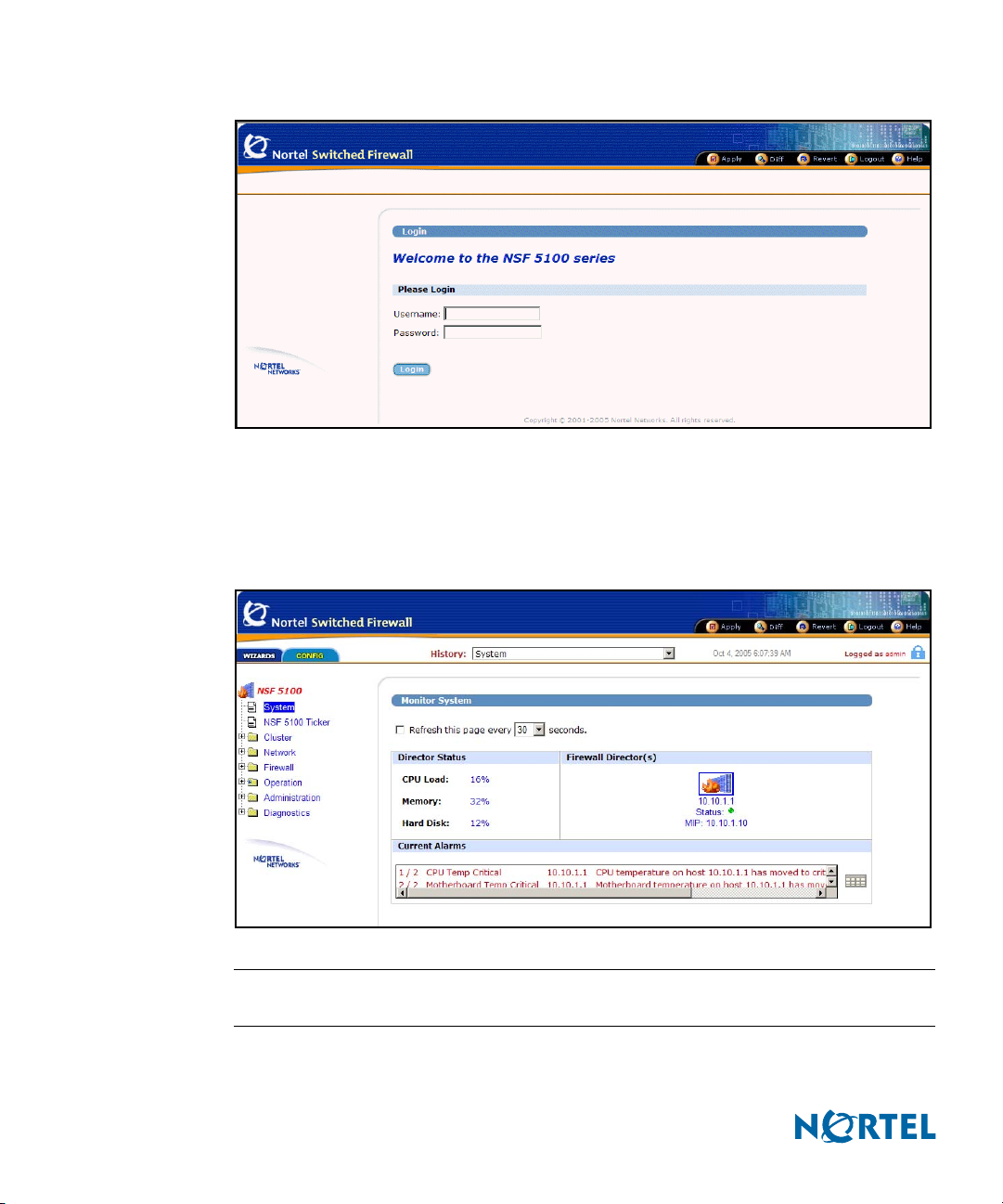
Figure 1 NSF Login window
Loading the main page
When the valid account name and password combination is entered on the login window, the
BBI default page appears in your browser viewing window (see Figure 2).
Figure 2 NSF BBI main page
16 Introduction
NOTE – A delay of a few seconds can occur while the default page collects data from all of the
cluster components. Do not stop the browser while loading is in progress.
216383-D October 2005
Page 17
CHAPTER 2
Basics of the Browser-Based Interface
Interface components
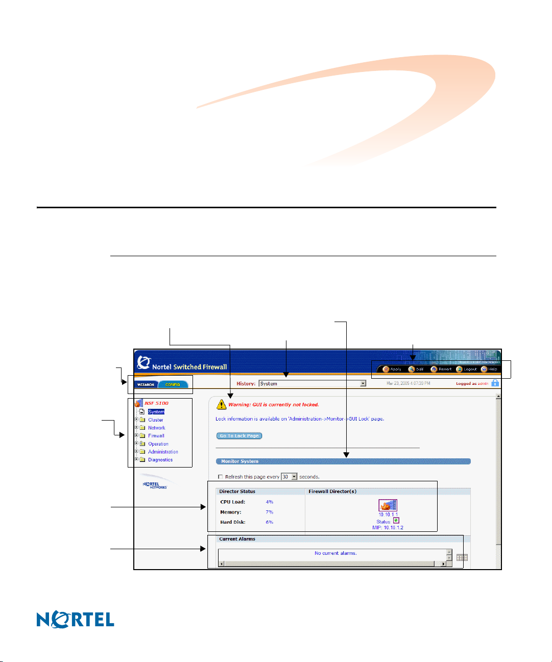
The Nortel Switched Firewall (NSF) Browser-Based Interface (BBI) main page has eight
component areas (see Figure 3).
Figure 3 NSF BBI main page
Main page tabs
NSF Configuration
main menu
Warning display area
History list
Forms display area
Global command buttons
Director status
Current alarms
216383-D October 2005
17
Page 18
Nortel Switched Firewall Browser-Based Interface Users Guide
Main page tabs
The two main page tabs are Wizards and Config (see Figure 3 on page 17).
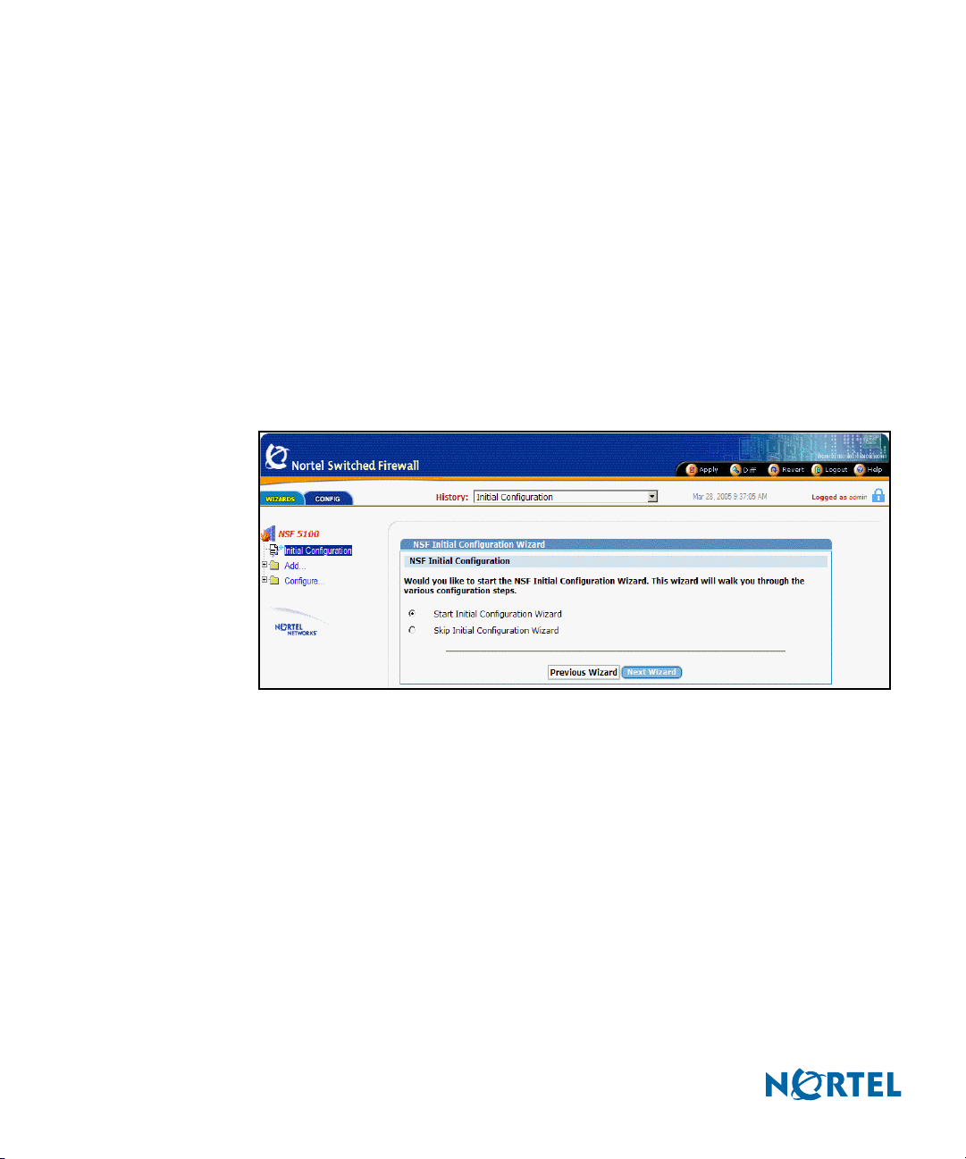
Wizards provides access to wizards that guide users through the processes of initial
configuration, interface and bridge addition, Check Point Firewall configuration,
routes and gateway configuration, DHCP Relay configuration, and OSPF configuration (see Figure 4 and Figure 5). To use the wizards, select Initial Configuration,
Add, or Configure, and follow the instructions on the page. Click the plus sign (+)
adjacent to a selection to expand it and reveal its associated subcategories. To see
each of the initial Wizards pages, see Chapter 3, Browser-Based Interface forms ref-
erence.
Config is the default tab for the BBI main page and provides access to all of the
monitoring and configuration functions (see Figure 6 on page 20).
Figure 4 NSF Wizards main page
18 Basics of the Browser-Based Interface
216383-D October 2005
Page 19
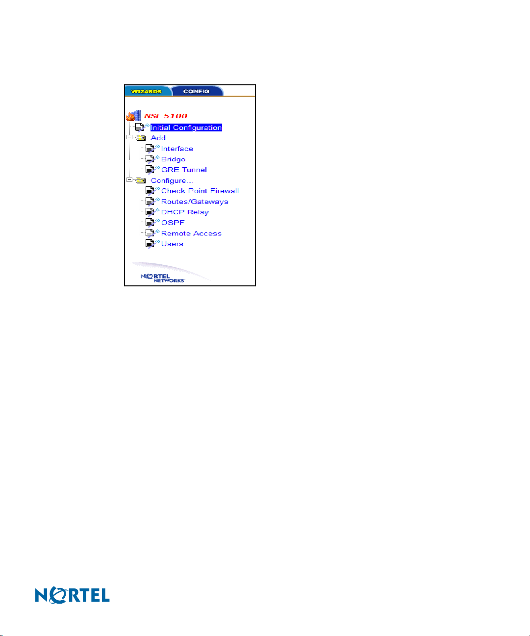
Nortel Switched Firewall Browser-Based Interface Users Guide
Wizards menu shows the selections available on the Wizards menu tree.
Figure 5 Wizards menu
216383-D October 2005
Basics of the Browser-Based Interface 19
Page 20
Nortel Switched Firewall Browser-Based Interface Users Guide
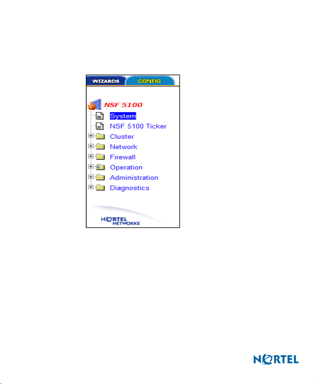
NSF Config main menu tree
Each of the selections on the Config main menu tree represents a page, called a form,
which provides a method to monitor or configure the NSF (see Figure 3 on page 17 and
Figure 6).
Figure 6 NSF Config main menu
Each main menu category offers subcategories, providing a further level of control or
detailed information. Click the plus sign (+) adjacent to a selection to expand it and reveal
its associated subcategories.
For detailed information about the forms, see Chapter 3, Browser-Based Interface forms
reference, on page 33.
Warning display area
The Warning display area provides important warnings for the user, such as information
about CLI users logged in or the status of the GUI lock. Any user logged in as administra-
tor (username admin) can activate the GUI lock before changing or creating a configura-
tion. See Figure 75 on page 107.
20 Basics of the Browser-Based Interface
216383-D October 2005
Page 21

Nortel Switched Firewall Browser-Based Interface Users Guide
History list
The History list displays the path to the current page. Up to nine of the most recently
visited pages are listed, most recent first. TIP: Click a list item to go directly to that page.
Forms display area
The Forms display area contains fields that display information or allow you to specify
information for configuring the system. The fields are different for each subpage.
Global command buttons
The global command buttons are always available at the top of each form (see Figure 3 on
page 17 and Figure 7).
Figure 7 Global command buttons
The global commands summon forms used for saving, examining, or canceling
configuration changes, for logging out, and for displaying Help information for the current
page (see Global command forms on page 24).
Director status appears on the left side of the forms display area, under the Monitor
System bar. Director status summarizes the status of the cluster, including CPU, memory,
and hard disk. The Firewall icon appears on the right side of the forms display area under
the Monitor System bar. TIP: Click the Firewall icon to go directly to the
Administration/Monitor/Director(s) form (see Figure 71 on page 103).
216383-D October 2005
The Firewall host IP address and Management IP address (MIP) appear under the
Firewall icon.
The status icon for the firewall appears between the addresses.
TIP: Click the Firewall icon to go directly to the Administration/Monitor/Director(s)
form (see Figure 71 on page 103).
o When the status icon is green, the firewall is operating, and when the status icon
is red, the firewall is offline.
Current alarms provides the current status of all active alarms.
Basics of the Browser-Based Interface 21
Page 22

Nortel Switched Firewall Browser-Based Interface Users Guide
Basic operation
The Browser-Based Interface for the Nortel Switched Firewall provides a variety of levels of
control. TIP: To access the full functionality of the BBI, you must log in as administrator
(username admin).
The BBI allows you to administer the NSF in the following manner (see Table 1).
Table 1 NSF administration
NSF function Administration method
Create a configuration Use the Config functions or Wizards.
Submit form changes Click Update or Submit on the form.
View pending changes Click global Diff.
Clear pending changes Click global Revert to cancel all pending changes.
Apply changes Click global Apply.
Up to ten simultaneous browser connections are allowed. When multiple CLI or BBI sessions
are open concurrently, only pending changes, made during your current session, are affected
by use of the global Diff, Revert, or Logout commands. However, when multiple CLI or BBI
administrators apply changes to the same set of parameters concurrently, the latest applied
changes take precedence. TIP: See Figure 75 on page 107, Administration/Monitor/GUI Lock
form. To prevent conflicts, any user logged in as administrator (username admin) can take
control of the GUI lock before changing or creating a configuration.
Pending change exceptions
After submission, most changes are considered pending and are not immediately put into effect
or permanently saved. However, changes to the date or time zone, and users and passwords
take effect as soon as the form is submitted. See Cluster/Time/Current Time form on page 40
and Administration/Users/General form on page 110.
Lost changes
Changes are lost if a new form is selected or the session is ended without submitting the
information to the pending configuration. Click Update or Submit on the form to submit
changes to the pending configuration.
22 Basics of the Browser-Based Interface
216383-D October 2005
Page 23

Nortel Switched Firewall Browser-Based Interface Users Guide
Pending changes are also discarded if you do not submit them before the inactivity timeout
value on BBI sessions elapses. The BBI inactivity timeout value is five minutes and cannot be
changed.
Creating a configuration
To create a configuration, do the following:
1) Select the appropriate menu item and subpage.
2) Modify fields in the appropriate forms display areas.
3) Click Update to submit the changes to the pending configuration.
Viewing pending changes
To view pending changes before they are applied, do the following:
1) Click global Diff .
2) View the global Diff form.
3) Click Back to return to the current form.
Clearing pending changes
To clear pending changes, do one of the following:
Click global Revert and return to the configuration. TIP: You cannot use the global
Revert command to restore the previous configuration after you submit the Apply
command.
Close the browser.
Submitting changes
To submit the form changes for application, do the following:
1) Click global Apply. TIP: The global Apply command allows updates on multiple forms
to be put into effect all at once. The Apply function validates the changes to the
configuration before applying them, and Apply fails if invalid settings are used. See
Figure 75 on page 107, Administration/Monitor/GUI Lock form. To prevent conflicts, any
user logged in as administrator (username admin) can take control of the GUI lock before
changing or creating a configuration.
216383-D October 2005
Basics of the Browser-Based Interface 23
Page 24
Nortel Switched Firewall Browser-Based Interface Users Guide
2) Click Submit.
See Global command forms for details on using Apply, Diff, Revert, and Logout.
Global command forms
The global command buttons are always available at the top of each form.
These buttons summon forms used to save, examine, or cancel configuration changes, log out,
and to display Help information. Each global command form provides options to verify or
cancel the command.
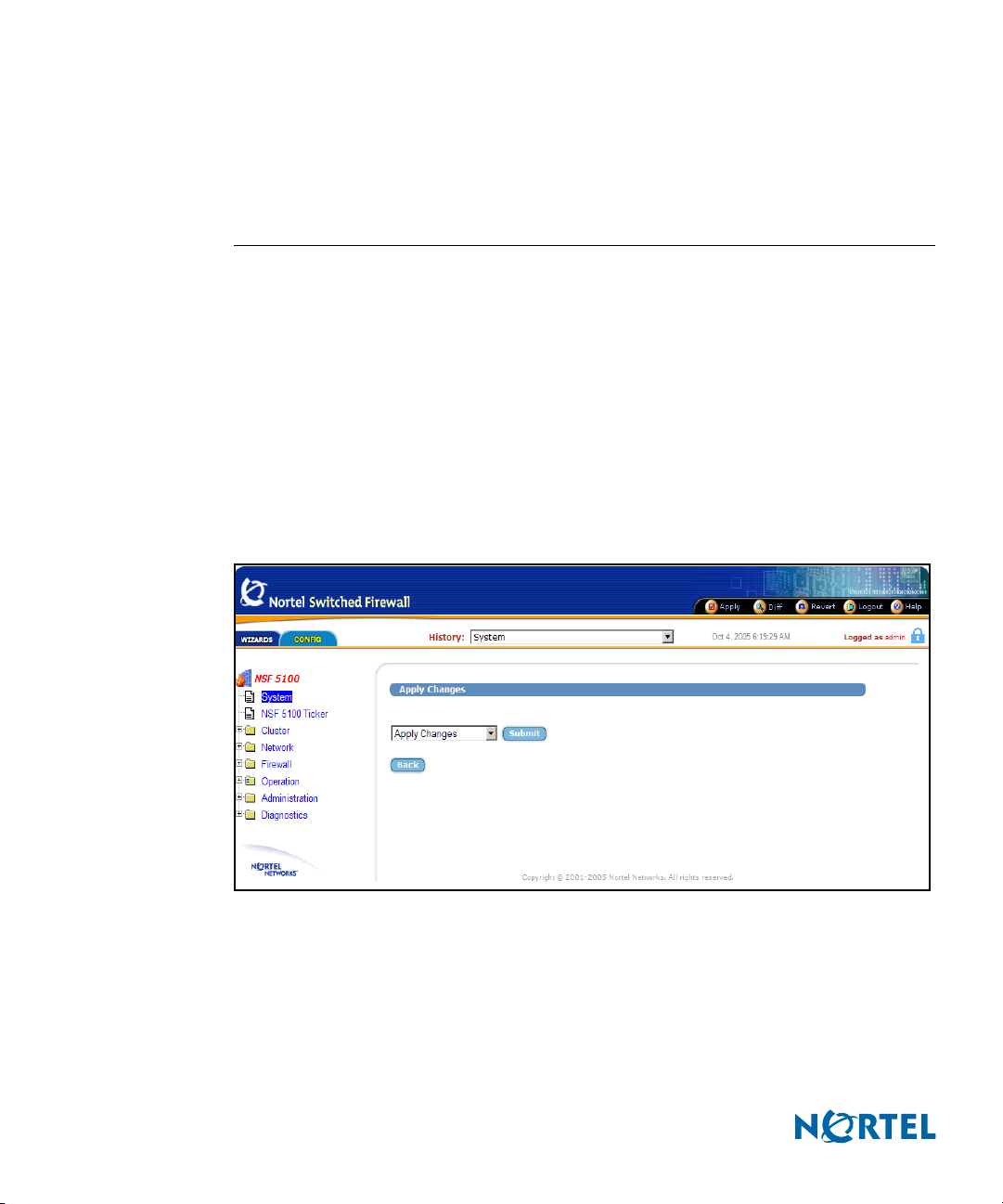
Apply Changes
Use the global Apply Changes form to check the validity of the pending configuration changes
for the current session, and to save the configuration changes and put them into effect (see
Figure 8).
Figure 8 Apply form
The global Apply form includes the following items:
Apply Changes list: to use this menu, select one of the following commands and click
Submit:
Apply Changes
24 Basics of the Browser-Based Interface
216383-D October 2005
Page 25

Nortel Switched Firewall Browser-Based Interface Users Guide
When selected, this command updates the Nortel Switched Firewall with any pending
configuration changes. Pending changes are first validated for correctness (see
Validate Configuration on page 25). If no problems are found, the changes are applied
and put into effect. If problems are found, applicable warning and error messages are
displayed. Warnings are allowed, and the changes are applied and put into effect.
Errors are not allowed, and the changes are not applied.
This command has no effect on pending changes in other open CLI or BBI sessions.
See Figure 75 on page 107 for information about taking control of the GUI lock.
Validate Configuration
When selected, this option validates pending changes for the current session, but does
not apply them. The pending configuration changes are examined to ensure that they
are complete and consistent.
If problems are found, the following types of messages are displayed:
Warnings are in yellow. Warnings identify conditions you should consider, but
which do not cause errors or prevent configuration application.
Errors are in red. Errors identify serious configuration problems that require
correction. Uncorrected errors cause the Apply Changes command to fail.
If the configuration is valid, select Apply Changes and click Submit to apply the
changes.
216383-D October 2005
Run a Security Audit
When selected, this command lists security information. Security information
includes the status for remote management features such as Telnet, SSH, and the BBI
for the cluster. The IP addresses that access the remote management features are also
listed. The Run Security Audit command also lists users configured with default
passwords that require change.
Submit button: Click to perform the action selected in the Apply Changes list.
Back button: Click to return to the previously viewed form without applying changes.
Basics of the Browser-Based Interface 25
Page 26
Nortel Switched Firewall Browser-Based Interface Users Guide
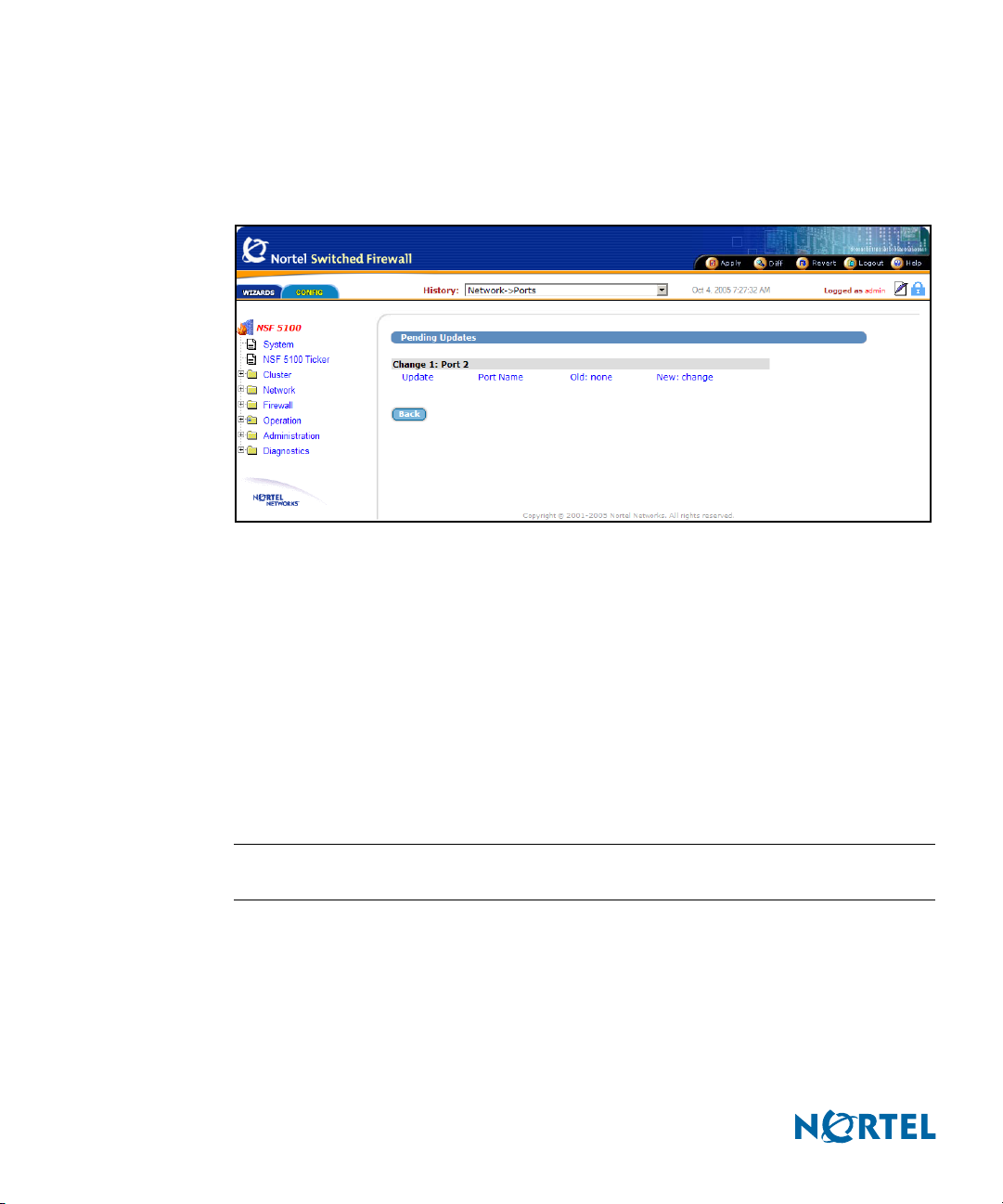
Diff
The global Diff command displays the Pending Updates form. Pending Updates provides a list
of the pending configuration changes for the current session (see Figure 9).
Figure 9 Diff form
The list displays a change record for each submitted update. Each record can consist of many
modifications, depending upon the complexity of the form and changes submitted.
Modifications are color-coded as follows:
Green: New items that will be added to the configuration when the global Apply
command is given and verified.
Blue: Existing items that will be modified.
Red: Configuration items that will be deleted.
The Diff list is cleared when configuration changes are applied or reverted, or when you log
out or close the browser window.
NOTE – The Diff form does not include pending changes made in other concurrent CLI or BBI
sessions.
26 Basics of the Browser-Based Interface
216383-D October 2005
Page 27
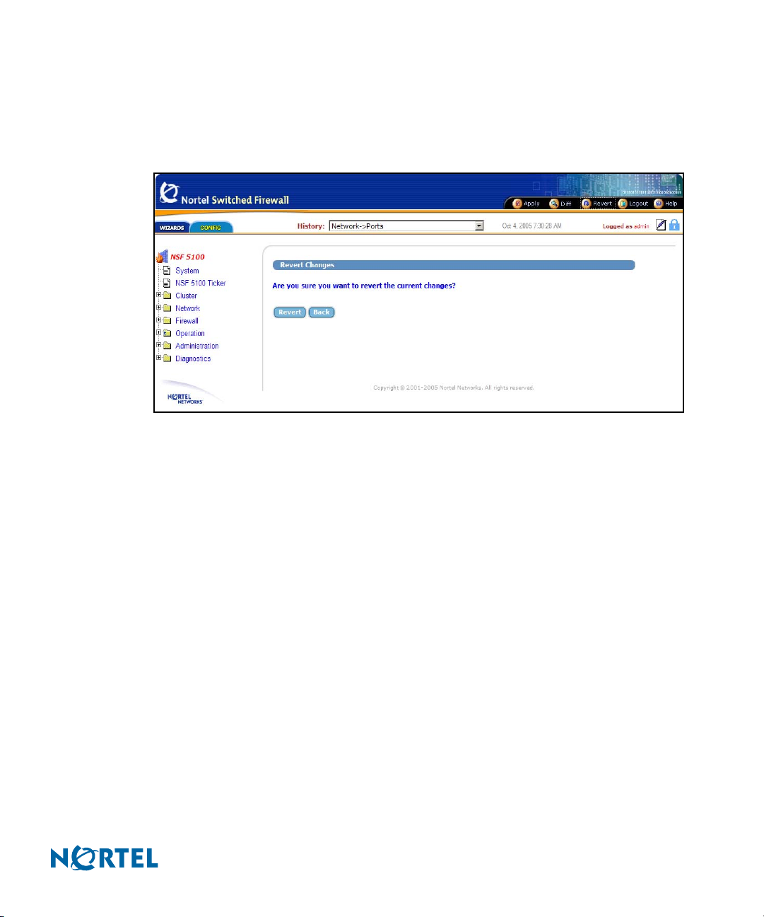
Nortel Switched Firewall Browser-Based Interface Users Guide
Revert
The global Revert command displays the Revert Changes form. Use Revert to cancel pending
configuration changes (see Figure 10).
Figure 10 Revert form
The global Revert form includes the following items:
Revert button: Click Revert to cancel the pending configuration changes for the current
session. TIP: Applied changes are not affected. Pending changes made in other open CLI
or BBI sessions are not affected. See Figure 75 on page 107, Administration/Monitor/GUI
Lock form. To prevent conflicts, any user logged in as administrator (username admin)
can take control of the GUI lock before changing or creating a configuration.
Back button: Click Back to return to the previously viewed form without canceling
pending changes.
216383-D October 2005
Basics of the Browser-Based Interface 27
Page 28
Nortel Switched Firewall Browser-Based Interface Users Guide
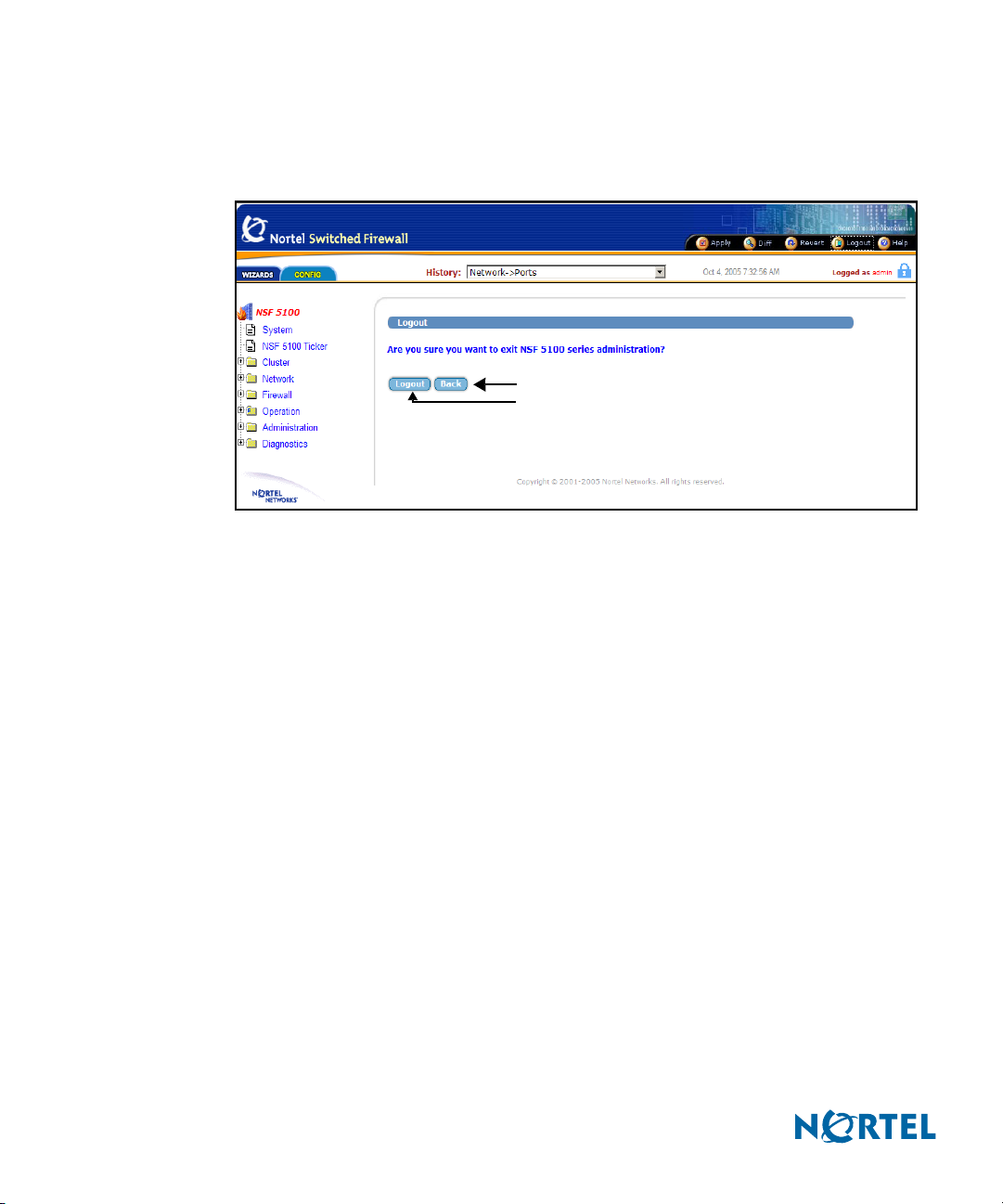
Logout
Use the global Logout form to terminate the current user session (see Figure 11).
Figure 11 Logout form
Back
Logout
The global Logout form includes the following items:
Logout button: Click Logout to terminate the current user session. TIP: Any
configuration changes made during this session that have not been applied are lost. This
command has no effect on pending changes in other open CLI or BBI sessions.
Back button: Click Back to return to the previously viewed form without logging out.
28 Basics of the Browser-Based Interface
216383-D October 2005
Page 29
Nortel Switched Firewall Browser-Based Interface Users Guide
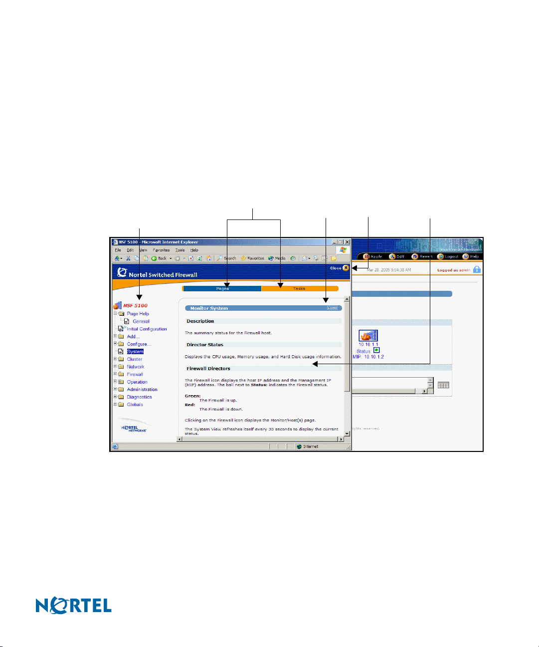
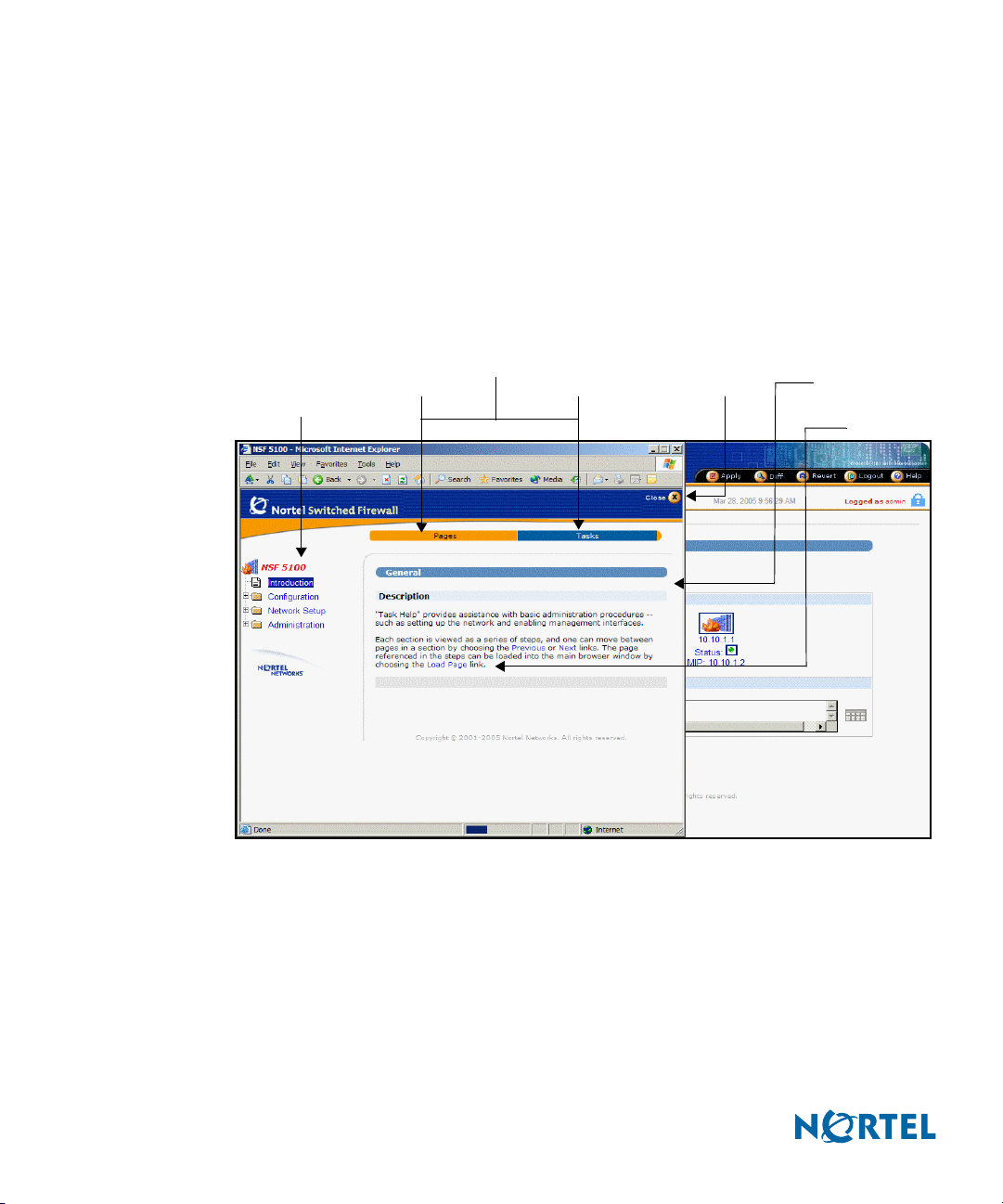
Help
The global Help form provides assistance with forms and tasks in the BBI. Two kinds of Help
are available: context-sensitive Help and task-based Help.
Context-sensitive Help
Context-sensitive Help displays detailed information about the currently displayed form in the
BBI forms area. Click global Help to view a new window showing Help information
appropriate to your current options (see Figure 12).
Figure 12 Context-sensitive Help form
Help topic
menu
Subpage menu
Pages
Ta sk s L oa d
Close
Forms area
216383-D October 2005
The context-sensitive Help window consists of the following areas:
Subpage menu: Click Pages to display Help for the selected form. Click Ta sk s to activate
the task-based Help system.
Help topic menu: Select a new Help topic using the menu on the left side of the Help
window. Each main menu item is listed, along with the submenu items under the current
selection. Select a different menu item to display its submenu list. Select any submenu
item to display Help for that form.
Load: Click Load to display the form referenced on the bar.
Basics of the Browser-Based Interface 29
Page 30
Nortel Switched Firewall Browser-Based Interface Users Guide
Forms area: This area displays detailed information about the selected topic.
Close button: Click Close to close the context-sensitive Help window.
Task-based Help
Task-based Help directs the administrator through the steps of various common procedures. To
access task-based Help, click global Help and then click the Tasks bar. The task Help menu
appears in a new window with information appropriate for the current BBI form (see Figure
13):
Figure 13 Task-based Help form
Task topic
menu
Subpage menu
Page Tasks
Close Forms area
Load Page
link
The task-based Help window consists of the following areas:
Subpage menu: Click Pages to display Help for the selected form. Click Ta sk s to activate
the task-based Help system (see Figure 13).
Task topic menu: Select from a list of tasks using the menu on the left side of the Help
window. Each main task item is listed, along with the subtasks under the current selection.
Select a different subtask to reveal the steps required to complete it.
Forms area: This area displays the steps required to complete the selected subtask.
30 Basics of the Browser-Based Interface
216383-D October 2005
Page 31

Nortel Switched Firewall Browser-Based Interface Users Guide
Load Page link: Click Load Page to display the form referenced on the task topic menu. If
the subtask has more than one step, the steps are listed on the form.
Click to display the information for the next subtask.
Click to display the information for the previous subtask.
Close button: Click Close to close the task-based Help window.
216383-D October 2005
Basics of the Browser-Based Interface 31
Page 32

Nortel Switched Firewall Browser-Based Interface Users Guide
32 Basics of the Browser-Based Interface
216383-D October 2005
Page 33

CHAPTER 3
Browser-Based Interface forms reference
BBI main menu selections
The following eight selections are available on the Nortel Switched Firewall (NSF) BrowserBased Interface (BBI) Config tab main menu:
System form on page 34
NSF 5100 Ticker form on page 34
Cluster forms on page 38
Network forms on page 50
Firewall forms on page 89
Operation forms on page 97
Administration forms on page 102
216383-D October 2005
Diagnostics forms on page 145
Pages, called forms, are available for each menu selection. Use these forms to configure,
manage, or obtain information about the NSF BBI.
The following selections are available on the NSF BBI Wizards tab main menu:
Initial Configuration
Add
Configure
For more information about the Wizards forms, see Wizards forms on page 154.
33
Page 34

Nortel Switched Firewall Browser-Based Interface Users Guide
System form
When you select System, the Main page, also known as the Monitor System form, is displayed
as shown in Monitor System form. For more information about the System form, see Interface
components on page 17.
Figure 14 Monitor System form
NSF 5100 Ticker form
NSF 5100 Ticker provides a real-time view of the following Firewall status and statistic
information:
status of firewall directors and accelerators
alarms, color coded for status
statistics for the following parameters:
CPU use
memory use
disk use
session statistics plotted as a graph
throughput statistics plotted as a graph
34 Browser-Based Interface forms reference
216383-D October 2005
Page 35

Nortel Switched Firewall Browser-Based Interface Users Guide
status of the following remote accesses:
HTTP
HTTPS
Teln et
SSH
SNMP
Use the NSF 5100 Ticker launch form to launch the Ticker. TIP: The Ticker cannot launch if
pop-up blockers are enabled (see NSF 5100 Ticker launch form).
NOTE – Java 2 Runtime Environment SE plug-in, version 1.2.4-01 or higher, is required.
When you launch the Ticker, if the Java plug-in is not present, the Ticker downloads it from
the java.sun.com web site. If the system is not connected to the Internet, an error message
appears in the Ticker window.
Figure 15 NSF 5100 Ticker launch form
216383-D October 2005
Click Launch on the NSF 5100 Ticker Launch form to launch the Ticker report.
Use the Ticker report form to view the statistics provided by the Ticker.
Browser-Based Interface forms reference 35
Page 36

Nortel Switched Firewall Browser-Based Interface Users Guide
The NSF 5100 Ticker report form displays three tabs (see NSF 5100 Ticker results form).
Figure 16 NSF 5100 Ticker results form
Tabs on the NSF 5100 Ticker results form are as follows:
Cluster information
Properties
About
The Cluster Information page displays the statistics and graphs for the Firewall (see NSF 5100
Ticker results form).
36 Browser-Based Interface forms reference
216383-D October 2005
Page 37

Nortel Switched Firewall Browser-Based Interface Users Guide
The Properties page displays properties for NSF 5100 Ticker parameters (see NSF 5100
Ticker/Properties form).
Figure 17 NSF 5100 Ticker/Properties form
The About page displays the NSF version and license information (see NSF 5100
Ticker/About form).
216383-D October 2005
Figure 18 NSF 5100 Ticker/About form
Browser-Based Interface forms reference 37
Page 38

Nortel Switched Firewall Browser-Based Interface Users Guide
Cluster forms
The Cluster menu includes the following categories of forms:
Director(s) form
Time forms
Current Time (see Cluster/Time/Current Time form on page 40)
NTP servers (see Cluster/Time/NTP Servers on page 41)
Logs
Syslog (see Cluster/Logs/Syslog form on page 42)
ELA (see Cluster/Logs/ELA form on page 45)
Archive (see Cluster/Logs/Archive form on page 47)
Warnings (see Cluster/Warnings form on page 49)
Director(s) form
Use the Cluster/Director(s) form to view and change the Firewall Director Settings (see
Cluster/Director(s) form).
Figure 19 Cluster/Director(s) form
Management General Settings Update
IP address
38 Browser-Based Interface forms reference
216383-D October 2005
Page 39

Nortel Switched Firewall Browser-Based Interface Users Guide
The Cluster/Director(s) form is divided into the following two sections:
Management IP Address
General Settings
Fields and buttons on the Cluster/Director(s) form are as follows:
Management IP Address
MIP is the Management IP for the host. MIP address identifies the cluster and must be
unique on the network.
General Settings
ID is the host identification number.
Hostname displays the name of the Firewall host.
IP Address is the network IP address for the host.
System Name is the set system name.
Actions provides the following three options:
oClick Halt to stop the Firewall. TIP: Always click Halt before turning the device
off.
oClick Reboot to reboot the Firewall.
oClick Delete to delete the member (host) and reset the configuration to factory
default settings.
216383-D October 2005
Click Update to submit changes to the pending configuration.
Browser-Based Interface forms reference 39
Page 40

Nortel Switched Firewall Browser-Based Interface Users Guide
Time forms
The two Cluster/Time forms are as follows:
Cluster/Time/Current Time (see Cluster/Time/Current Time form)
Cluster/Time/NTP Servers (see Cluster/Time/NTP Servers form on page 41)
Cluster/Time/Current Time form
Use the Cluster/Time/Current Time form to set the date and time for the cluster (see
Cluster/Time/Current Time form).
Figure 20 Cluster/Time/Current Time form
The Cluster/Time/Current Time form is divided into the following two sections:
Date
Timezone
Fields and buttons on the Cluster/Time/Current Time form are as follows:
Date fields
Month provides a list to select the current month.
Day provides a list to select the current date.
Year provides a list to select the current year.
40 Browser-Based Interface forms reference
216383-D October 2005
Page 41

Nortel Switched Firewall Browser-Based Interface Users Guide
Hour provides a list to select the current hour.
Minute provides a list to select the current minute.
Click Save to submit the date and time changes and to put the changes into immediate
effect. Note that changes to the date and time zone are unlike most changes; they are not
considered pending after submission.
Timezone provides a list to select the region.
Click Save to submit the time zone changes and to put the changes into immediate effect.
Note that changes to the date and time zone are unlike most changes; they are not
considered pending after submission.
Cluster/Time/NTP Servers form
Use the Cluster/Time/NTP Servers form to specify the Network Time Protocol (NTP) servers
(see Cluster/Time/NTP Servers).
Figure 21 Cluster/Time/NTP Servers
216383-D October 2005
NTP servers are used by the NTP client on the NSF to synchronize its clock. The system
should have access to at least three servers to compensate for discrepancies between the
servers.
Browser-Based Interface forms reference 41
Page 42

Nortel Switched Firewall Browser-Based Interface Users Guide
Fields and buttons on the Cluster/Time/NTP Servers form are as follows:
IP Address displays the IP address of an NTP server.
Action—if an NTP server is present, a Delete button appears.
Click Delete to delete the server.
New NTP IP provides a field to configure a new NTP server. TIP: Use dotted decimal
notation.
Update submits the NTP server address changes to the pending configuration.
Logs forms
The three Cluster/Logs forms are as follows:
Syslogs (see Cluster/Logs/Syslog form)
ELA (see Cluster/Logs/ELA form on page 45)
Archive (see Cluster/Logs/Archive form on page 47)
Cluster/Logs/Syslog form
Use the Cluster/Logs/Syslog form to specify remote system log servers and turn on local log
debugging (see Cluster/Logs/Syslog form).
Figure 22 Cluster/Logs/Syslog form
42 Browser-Based Interface forms reference
216383-D October 2005
Page 43

Nortel Switched Firewall Browser-Based Interface Users Guide
Fields and buttons on the Cluster/Logs/Syslog form are as follows:
System Log
Debug Messages displays a list with two choices.
Disabled disables transmission of debug messages to the local system log.
Enabled enables transmission of debug messages to the local system log.
Source IP Mode displays a list with three choices.
Auto, the default setting, specifies the IP address of the outgoing interface.
Unique specifies the IP address of the individual NSF.
MIP specifies the IP address of the cluster MIP. Use this setting with applications
designed for devices limited to one IP address (for example, some versions of
HP OpenView).
Update submits the debug message status change and the source IP mode change to the
pending configuration.
The Remote Syslog Servers section of the Cluster/Logs/Syslog form is divided into the
following two sections:
Current Remote Syslog Servers
Add New Remote Syslog Server
Current Remote Syslog Servers displays the following fields:
IP Address specifies the remote syslog server in dotted decimal notation.
Logging Severity specifies the severity of messages logged. All messages of the selected
severity or higher are logged.
Facility provides the local facility number used to uniquely identify syslog entries.
Action—Click Delete to delete an active remote server.
Add New Remote Syslog Server displays the following fields:
New Server IP specifies the IP address for the remote syslog server. TIP: Enter the IP
address in dotted decimal notation.
New Server Severity specifies the severity of messages logged. The following selections
are presented in the list:
emerg
alert
216383-D October 2005
Browser-Based Interface forms reference 43
Page 44

Nortel Switched Firewall Browser-Based Interface Users Guide
crit
err
warning
notice
info
debug
New Server Facility provides a list with the following local facility numbers used to
uniquely identify syslog entries:
auto
local0
local1
local2
local3
local4
local5
local6
local7
Click Update to submit the Remote Syslog Server changes to the pending configuration.
44 Browser-Based Interface forms reference
216383-D October 2005
Page 45

Nortel Switched Firewall Browser-Based Interface Users Guide
Cluster/Logs/ELA form
Use the Cluster/Logs/ELA form to configure Event Logging API (ELA) (see
Cluster/Logs/ELA form).
ELA allows Firewall log messages to be sent to a Check Point SmartCenter Server for display
through the Check Point SmartView Tracker.
Figure 23 Cluster/Logs/ELA form
216383-D October 2005
NOTE – Configure an ELA service on the Check Point management station and transfer a SIC
Certificate for the service to the Firewall to enable ELA logging. For configuration details, see
the Nortel Switched Firewall 2.3.3 User’s Guide and Command Reference, (213455-L).
The Cluster/Logs ELA (Check Point ELA Log) form is divided into the following two
sections:
General Settings
Pull SIC Certificate
General Settings displays the following fields:
Status displays a list with two choices:
Disabled disables Check Point ELA logging.
Enabled enables Check Point ELA logging.
Browser-Based Interface forms reference 45
Page 46

Nortel Switched Firewall Browser-Based Interface Users Guide
Management Station IP provides an entry field to specify the IP address of the Check
Point SmartCenter Server where the Firewall log messages are sent.
Minimum Severity provides a list that specifies the severity of messages logged and sent
to the ELA service.
emerg
alert
crit
err
warning
notice
info
debug
Management Station DN is the designated name of the Check Point SmartCenter Server.
Update submits the form changes to the pending configuration.
Pull SIC Certificate displays the following fields:
Firewall Director IP provides a list to specify the IP address of the individual Firewall for
update. TIP: Do not use the MIP address.
OPSEC Application Name is the name of the ELA service configured on the Check Point
SmartCenter Server. Use the name specified when creating the OPSEC application in the
Check Point SmartDashboard. TIP: Use a different OPSEC application for each Firewall.
OPSEC Password is the password used to configure the ELA service on the Check Point
Management Station.
OPSEC Password (again) is used to verify the password.
Submit is used to submit the form and update the certificate on the specified Firewall.
46 Browser-Based Interface forms reference
216383-D October 2005
Page 47

Nortel Switched Firewall Browser-Based Interface Users Guide
Cluster/Logs/Archive form
Use the Cluster/Logs/Archive form to specify system log rotation and system log archiving
parameters (see Cluster/Logs/Archive form).
Figure 24 Cluster/Logs/Archive form
216383-D October 2005
Fields and buttons on the Cluster/Logs/Archive form are as follows:
Email specifies an e-mail address for the administrator receiving the log.
SMTP Server IP specifies the IP address of the SMTP server in dotted decimal notation.
TIP: The SMTP Server must be configured to accept messages from the Firewall and a
Check Point policy must be present to allow these messages through the Firewall.
Rotate Size specifies the maximum size the log reached before rotation. If this parameter
is set at 0, then the size is ignored and only the log rotate interval is used.
Interval specifies, in days and hours, the interval at which the system log file is rotated.
Update submits the form changes to the pending configuration.
Log file rotation
Log files are rotated when the file reaches a specific size or age.
If the log file rotate size is set to 0, the file size is ignored and the rotate interval is used to
determine log rotation. TIP: Set the rotate interval in days and hours.
Browser-Based Interface forms reference 47
Page 48

Nortel Switched Firewall Browser-Based Interface Users Guide
If the log file rotate size is set to >0, log rotation occurs when one of the following conditions
is met:
The log file surpasses the rotate size.
The log file rotation interval is reached.
Rotated log files are managed in one of the following ways when rotation occurs:
The rotated log file is set aside.
The rotated log file is e-mailed. TIP: Specify an e-mail address and SMTP server IP
address.
When the log file is rotated, a new log file is started.
48 Browser-Based Interface forms reference
216383-D October 2005
Page 49

Nortel Switched Firewall Browser-Based Interface Users Guide
Warnings form
Use the Cluster/Warnings form to enable or disable configuration warning messages (see
Cluster/Warnings form).
Figure 25 Cluster/Warnings form
216383-D October 2005
Fields and buttons on the Cluster/Warnings form are as follows:
Warnings displays a list with two selections.
Disabled disables the display of warning messages about the state of pending
configuration changes when the global Apply command is issued.
Enabled enables the display of warning messages about the state of pending
configuration changes when the global Apply command is issued.
Update submits the Warning selection to the pending configuration.
Browser-Based Interface forms reference 49
Page 50

Nortel Switched Firewall Browser-Based Interface Users Guide
Network forms
The Network menu includes the following categories of forms:
DNS (see Network/DNS form on page 51)
Ports (see Network/Ports form on page 52)
Routes
Static (see Network/Routes/Static form on page 54)
Proxy ARP (see Network/Routes/Proxy ARP form on page 57)
Gateway (see Network/Routes/Gateway form on page 58)
OSPF
o General (see Network/Routes/OSPF/General form on page 59)
o Area Indexes (see Network/Routes/OSPF/Area Indexes form on page 60)
o Interfaces (see Network/Routes/OSPF/Interfaces form on page 62)
o GRE Tunnels (see Network/Routes/OSPF/GRE Tunnels form on page 64)
o Redistribute (see Network/Routes/OSPF/Redistribute form on page 67)
DHCP Relay
General (see Network/DHCP Relay/General form on page 69)
Interfaces (see Network/DHCP Relay/Interfaces form on page 70)
Servers (see Network/DHCP Relay/Servers form on page 72)
Interfaces (see Network/Interfaces form on page 74)
Bridges (see Network/Bridges form on page 78)
VRRP (see Network/VRRP form on page 80)
GRE Tunnels (see Network/GRE Tunnels form on page 82)
Status
Interface (see Network/Status/Interface form on page 85)
Link (see Network/Status/Link form on page 86)
Bridge Statistics (see Network/Status/Bridge Statistics form on page 87)
Bridge Mac Entries (see Network/Status/Bridge Mac Entries form on page 88)
50 Browser-Based Interface forms reference
216383-D October 2005
Page 51

Nortel Switched Firewall Browser-Based Interface Users Guide
NOTE – The NSF provides administrators with the option to configure Layer 2 and Layer 3
firewalls. The Layer 2 and Layer 3 firewall configuration procedures differ only in the
configuration of the IP addresses. A Layer 3 firewall requires valid IP addresses for address 1
and address 2. A Layer 2 firewall requires no IP addresses. For detailed Layer 2 and Layer 3
configuration, see Nortel Switched Firewall 2.3.3 User’s Guide and Command Reference,
(213455-L).
DNS form
Use the Network/DNS form to specify the Domain Name Service (DNS) servers. Multiple
servers are allowed (see Network/DNS form).
Figure 26 Network/DNS form
216383-D October 2005
Fields and buttons on the Network/DNS form are as follows:
IP Address specifies the IP address of a configured DNS server.
Action displays a Delete button if a DNS server is present.
New DNS IP provides an entry field to specify a new DNS server address. TIP: Use
dotted decimal notation.
Update submits the DNS server address changes to the pending configuration.
Browser-Based Interface forms reference 51
Page 52

Nortel Switched Firewall Browser-Based Interface Users Guide
Ports form
Use the Network/Ports form to configure network port settings (see Network/Ports form).
Figure 27 Network/Ports form
Fields and buttons on the Network/Ports form are as follows:
Port# specifies the port number on the Firewall.
Name provides the name of the port.
Autonegotiation provides two choices:
Yes indicates that autonegotiation is enabled.
No indicates that autonegotiation is disabled.
Speed specifies the port data rate, in Mbps, of 0, 10, 100, or 1000. TIP: Port speed is not
applicable if autonegotiation is enabled.
Mode provides two duplex options:
Half
Full
Action provides the option to modify a form and update port settings (see Network/Ports
Modify Port formFigure 28 on page 53).
52 Browser-Based Interface forms reference
216383-D October 2005
Page 53

Nortel Switched Firewall Browser-Based Interface Users Guide
Network/Ports Modify Port form
Use the Network/Ports Modify Port form to modify the settings for a selected port.
Figure 28 Network/Ports Modify Port form
The following fields can be modified on the Network/Ports Modify Port form:
Identifier provides an entry field for a port number. TIP: Select a number between
1 and 6.
Name provides an entry field to specify a name for the port.
Autonegotiation Status provides a list with the following two selections:
Enabled enables port autonegotiation. TIP: Port speed setting is ignored if
autonegotiation is enabled.
Disabled disables port autonegotiation.
Speed provides a list with the following selections:
0 Mbps
10 Mbps
100 Mbps
1000 Mbps
216383-D October 2005
Browser-Based Interface forms reference 53
Page 54

Nortel Switched Firewall Browser-Based Interface Users Guide
Mode provides for following two selections:
Half (duplex)
Full (duplex)
Update submits the port changes to the pending configuration.
Back returns to the Network/Ports form without submitting changes to the pending
configuration.
Routes forms
Following are the four main categories of forms in the Network/Routes menu:
Static (see Network/Routes/Static form)
Proxy ARP (see Network/Routes/Proxy ARP form on page 57)
Gateway (see Network/Routes/Gateway form on page 58)
OSPF (see Network/Routes/OSPF/General form on page 59)
Network/Routes/Static form
Use the Network/Routes/Static form to view and configure static routes on the Firewall (see
Network/Routes/Static form).
Figure 29 Network/Routes/Static form
54 Browser-Based Interface forms reference
216383-D October 2005
Page 55

Nortel Switched Firewall Browser-Based Interface Users Guide
Fields and buttons on the Network/Routes/Static form are as follows:
Destination IP specifies the IP address of the route destination. TIP: Use dotted decimal
notation.
Destination Mask specifies the subnet mask for the route destination. TIP: Use dotted
decimal notation.
Gateway IP specifies the IP address of the gateway. TIP: Use dotted decimal notation.
Actions provides two choices, which are visible only if routes are present:
Delete, to delete a route from the system.
Modify, to modify the parameters of a displayed route (see Network/Routes/Static
Modify Route form).
Add New Route adds a new route to the configuration (see Network/Routes/Static Add
Route form on page 56).
Network/Routes/Static Modify Route form
Use the Network/Routes/Static Modify Route form to modify the parameters of a displayed
route.
Figure 30 Network/Routes/Static Modify Route form
Fields and buttons on the Network/Routes/Static Modify Route form are as follows:
Destination IP specifies the IP address of the route destination. TIP: Use dotted decimal
notation.
Destination Mask specifies the subnet mask for the route destination. TIP: Use dotted
decimal notation.
Gateway IP specifies the IP address of the gateway. TIP: Use dotted decimal notation.
Update submits the changes to the pending configuration.
216383-D October 2005
Browser-Based Interface forms reference 55
Page 56

Nortel Switched Firewall Browser-Based Interface Users Guide
Back returns to the Network/Routes/Static form without submitting changes to the
pending configuration.
Network/Routes/Static Add Route form
Use the Network/Routes/Static Add Route form to add a new static route to the configuration.
Figure 31 Network/Routes/Static Add Route form
Fields and buttons on the Network/Routes/Static Add Route form are as follows:
Destination IP specifies the IP address of the route destination. TIP: Use dotted decimal
notation.
Destination Mask specifies the subnet mask for the route destination. TIP: Use dotted
decimal notation.
Gateway IP specifies the IP address of the gateway. TIP: Use dotted decimal notation.
Update submits the changes to the pending configuration.
Back returns to the Network/Routes/Static form without submitting changes to the
pending configuration.
56 Browser-Based Interface forms reference
216383-D October 2005
Page 57

Nortel Switched Firewall Browser-Based Interface Users Guide
Network/Routes/Proxy ARP form
Use the Network/Routes/Proxy ARP (Address Resolution Protocol) form to view and
configure the Proxy ARP status and addresses that allow the Firewall to respond to Proxy ARP
requests (see Network/Routes/Proxy ARP form).
Figure 32 Network/Routes/Proxy ARP form
216383-D October 2005
The Network/Routes/Proxy ARP form is divided into the following two sections:
General
Proxy ARP Addresses
Fields and buttons on the form are as follows:
General
Proxy Status contains a list displaying the following selections:
o Disabled disables Proxy ARP for the cluster.
o Enabled enables Proxy ARP for the cluster.
Update submits the Proxy status change to the pending configuration.
Proxy ARP Addresses
IP Address lists the IP addresses for which the Proxy provides ARPs in the cluster.
VRRP Group lists the VRRP group, if VRRP is set up, for which the Proxy provides
ARPs in the cluster.
Action provides the delete selection used to delete the IP address if at least one Proxy
ARP address is present.
Browser-Based Interface forms reference 57
Page 58

Nortel Switched Firewall Browser-Based Interface Users Guide
New Proxy ARP IP provides an entry field to specify an IP address. TIP: Use dotted
decimal format.
VRRP Group provides a list for VRRP group 1 or 2 selection.
Update submits the IP address changes to the pending configuration.
Network/Routes/Gateway form
Use the Network/Routes/Gateway form to specify the default gateway for the Firewall (see
Network/Routes/Gateway form).
Figure 33 Network/Routes/Gateway form
Fields and buttons on the Network/Routes/Gateway form are as follows:
Gateway provides an entry field to configure the gateway for the system. TIP: Use dotted
decimal notation.
Update submits the form changes to the pending configuration.
58 Browser-Based Interface forms reference
216383-D October 2005
Page 59

Nortel Switched Firewall Browser-Based Interface Users Guide
Network/Routes/OSPF forms
Following are the categories of Network/Routes/OSPF forms:
General (see Network/Routes/OSPF/General form)
Area Indexes (see Network/Routes/OSPF/Area Indexes form on page 60)
Interfaces (see Network/Routes/OSPF/Interfaces form on page 62)
GRE Tunnels (see Network/Routes/OSPF/GRE Tunnels form on page 64)
Redistribute (see Network/Routes/OSPF/Redistribute form on page 67)
Network/Routes/OSPF/General form
Use the Network/Routes/OSPF/General form to view and change the dynamic routing settings
for OSPF (see Network/Routes/OSPF/General form).
Figure 34 Network/Routes/OSPF/General form
216383-D October 2005
Fields and buttons on the Network/Route/OSPF/General form are as follows:
Status displays a list with the following selections:
Disabled disables OSPF.
Enabled enables OSPF.
Spf Interval provides an entry field to set the time interval, in seconds, between each
calculation of the Shortest Path First (SPF).
Spf Hold Time provides an entry field to set the minimum time OSPF retains a shortest-
path calculation result to prevent another calculation from occurring too soon.
Browser-Based Interface forms reference 59
Page 60

Nortel Switched Firewall Browser-Based Interface Users Guide
Router Id 1 provides an entry field to set the OSPF Router ID for the first Firewall host.
TIP: OSPF uses the router ID to identify the routing device. If no router ID is specified, or
if the router ID is set to 0.0.0.0, the Firewall host is automatically selected as the router ID.
Router Id 2 provides an entry field to set the OSPF Router ID for the second Firewall host.
Save Setting submits the changes to the pending configuration.
Network/Routes/OSPF/Area Indexes form
Use the Network/Routes/OSPF/Area Indexes form to view and change the OSPF Area Index
settings (see Network/Routes/OSPF/Area Indexes form).
Figure 35 Network/Routes/OSPF/Area Indexes form
Fields and buttons on the Network/Routes/OSPF/Area Indexes form are as follows:
Id provides the index number for the Area Index attached to the Firewall.
Enabled indicates whether the Area Index is enabled or disabled.
Area Id provides the IP address identifying the Area Index.
Type indicates whether the Area Index is Transit (default) or Stub.
Actions provides the following selections if an Area ID is present:
Delete deletes the Area Index adjacent to the button.
Modify opens a form for modifying the Area Index adjacent to the button.
Add New Area Index opens a form for configuring a new Area Index (see
Network/Routes/OSPF/Area Indexes Add Area Index form on page 61).
60 Browser-Based Interface forms reference
216383-D October 2005
Page 61

Nortel Switched Firewall Browser-Based Interface Users Guide
Network/Routes/OSPF/Area Indexes Add New form
Use the Network/Routes/OSPF/Area Indexes Add New form to configure a new Area Index.
Figure 36 Network/Routes/OSPF/Area Indexes Add Area Index form
Fields and buttons on the Network/Routes/OSPF/Area Indexes Add Area Index form are as
follows:
Identifier provides a list with a numbers in a range from 1 to 16.
Status provides a list with the following two selections:
Enabled enables the area.
Disabled disables the area.
Area Id provides an entry field to set the OSPF area number. TIP: Use dotted decimal
notation.
Type provides a list with the following two selections to set the area type:
transit
stub
Update submits the changes to the pending configuration.
Back returns to the Network/Routes/OSPF/Area Indexes form without submitting changes
to the pending configuration.
216383-D October 2005
Browser-Based Interface forms reference 61
Page 62

Nortel Switched Firewall Browser-Based Interface Users Guide
Network/Routes/OSPF/Interfaces form
Use the Network/Routes/OSPF/Interfaces form to display and change the OSPF Interfaces
settings that are required to attach an IP network to an OSPF area (see
Network/Routes/OSPF/Interfaces form).
Figure 37 Network/Routes/OSPF/Interfaces form
Fields and buttons on the Network/Routes/OSPF/Interfaces form are as follows:
Id provides a numerical ID, between 1 and 255, for the interface.
Enabled indicates OSPF Interfaces status as Yes or No.
Area Index sets the OSPF area index to attach to the network for the current IP interface.
Action provides a Modify button used to access a form to modify or update the OSPF
Interfaces. The Modify form displays a modified interface if interfaces are present (see
Network/Routes/OSPF/Interfaces Modify form on page 63).
62 Browser-Based Interface forms reference
216383-D October 2005
Page 63

Nortel Switched Firewall Browser-Based Interface Users Guide
Network/Routes/OSPF/Interfaces Modify form
Use the Network/Routes/OSPF/Interfaces Modify form to modify a selected interface.
Figure 38 Network/Routes/OSPF/Interfaces Modify form
Fields and buttons on the Network/Routes/OSPF/Interfaces Modify form are as follows:
216383-D October 2005
Identifier sets the numerical ID for the interface between 1 and 255.
Status provides a list with the following two options:
enabled enables the interface operational status.
disabled disables the interface operational status.
Area Index provides a list to set the OSPF area index to attach to the network for this IP
interface.
Priority sets the IP interface (IF) priority used when electing a Designated Router (DR)
and Backup Designated Router (BDR) for the area. TIP: The default is 1.
Cost 1 provides an entry field to set the cost of output routes for first Firewall host.
Cost 2 provides an entry field to set the cost of output routes for the second Firewall host.
Hello provides an entry field to set the hello interval in seconds.
Dead provides an entry field to set the router dead interval in seconds.
Transmit provides a list to set the transmit delay in seconds.
Retransmit provides a list to set the time interval in seconds.
Browser-Based Interface forms reference 63
Page 64

Nortel Switched Firewall Browser-Based Interface Users Guide
Authentication provides a list to set the authentication type for the interface, with the
following selections:
None
Password
MD5
Key provides an entry field to set the password used for OSPF authentication when the
authentication options is set to password.
MD5 Auth Key provides an entry field to set the password used for OSPF authentication
when the authentication options is set to MD5.
Update submits the changes to the pending configuration.
Back returns to the Network/Routes/OSPF Interfaces without submitting the changes to
the pending configuration.
Network/Routes/OSPF/GRE Tunnels form
Use the Network/Routes/OSPF/GRE Tunnels form to display and change the GRE tunnels (see
Network/Routes/OSPF/GRE Tunnels form).
Figure 39 Network/Routes/OSPF/GRE Tunnels form
Fields and buttons on the Network/Routes/OSPF/GRE Tunnels form are as follows:
Id provides the numerical ID for the GRE tunnel.
Enabled provides the status of the GRE tunnel.
64 Browser-Based Interface forms reference
216383-D October 2005
Page 65

Nortel Switched Firewall Browser-Based Interface Users Guide
Area Index sets the OSPF area index to attach to the network for the current GRE Tunnel.
Action provides the following two options:
Delete deletes a selected GRE tunnel.
Modify provides a form to modify a selected GRE tunnel (see
Network/Routes/OSPF/GRE Tunnels Modify form).
Network/Routes/OSPF/GRE Tunnels Modify form
Use the Network/Routes/OSPF/GRE Tunnels Modify form to modify GRE tunnel settings.
Figure 40 Network/Routes/OSPF/GRE Tunnels Modify form
216383-D October 2005
Fields and buttons on the Network/Routes/OSPF/GRE Tunnels Modify form are as follows:
Identifier provides the numerical ID of the GRE tunnel.
Status provides a list with the following two choices:
Enabled enables the GRE tunnel.
Disabled disables the GRE tunnel.
Area Index provides a list to select a value to set the OSPF area index to attach to the
network for the current GRE Tunnel.
Browser-Based Interface forms reference 65
Page 66

Nortel Switched Firewall Browser-Based Interface Users Guide
Priority provides a list to set the GRE Tunnel priority used to elect a Designated Router
(DR) and Backup Designated Router (BDR) for the area. TIP: A value of 0 specifies that
the elected GRE Tunnel is DROTHER and cannot be used as a DR or BDR.
Cost1 provides an entry field to set the cost of output routes for the first Firewall host.
TIP: Cost is based on bandwidth. Low cost indicates high bandwidth.
Cost 2 provides an entry field to sets the cost of output routes for the second Firewall host.
Hello provides an entry field to set the hello interval in seconds. TIP: The value must be
the same on all routing devices within the area.
Dead provides an entry field to set the router dead interval value, in seconds. TIP: The
dead value is typically four times the value of "hello." This value must be the same on all
routing devices within the same area.
Transmit provides a list to set the transmit delay, in seconds. TIP: This value must be the
same on all routing devices within the area.
Retransmit provides a list to set the time interval, in seconds, between each transmission
of LSAs to adjacencies on this GRE Tunnel. TIP: This value must be the same on all
routing devices within the area.
Authentication provides a list to set the authentication type.
Key provides an entry field to specify the password to be used for OSPF authentication.
TIP: Specify a type 1 (plain text) password of up to 16 characters.
MD5 Auth Key provides an entry field to set the password to be used for OSPF
authentication. TIP: Specify a password of up to 16 characters.
Update submits the OSPF GRE changes to the pending configuration and returns to the
Network/Routes/OSPF/GRE form.
Back returns to the Network/Routes/OSPF/GRE Tunnels page without submitting the
OSPF GRE settings to the pending configuration.
66 Browser-Based Interface forms reference
216383-D October 2005
Page 67

Nortel Switched Firewall Browser-Based Interface Users Guide
Network/Routes/OSPF/Redistribute form
Use the Network/Routes/OSPF/Redistribute form to display and modify the OSPF
Redistribution settings (see Network/Routes/OSPF/Redistribute form).
Figure 41 Network/Routes/OSPF/Redistribute form
Fields and buttons on the Network/Routes OSPF/Redistribute form are as follows:
OSPF Redistribution displays the following three settings:
Connected
Static
Default Gateway
Enabled
Yes indicates that the setting is enabled.
No indicates that the setting is disabled.
Metric is the numeric value used by OSPF for all redistributed routes.
Metric Type is the OSPF exterior metric type for redistributed routes.
RMAP is the OSPF Connected Redistribute RMAP number.
Action provides the following selection:
Modify provides a form to modify the connected route redistribution (see
Network/Routes/OSPF/Redistribute Modify form on page 68).
216383-D October 2005
Browser-Based Interface forms reference 67
Page 68

Nortel Switched Firewall Browser-Based Interface Users Guide
Network/Routes/OSPF/Redistribute Modify form
Use the Network/Routes/OSPF/Redistribute Modify form to modify the connected route
redistribution.
Figure 42 Network/Routes/OSPF/Redistribute Modify form
Fields and buttons on the Network/Routes/OSPF/Redistribute Modify form are as follows:
Status provides a list with two selections:
enabled enables the connected route redistribution
disabled disables the connected route redistribution
Metric provides an entry field for the metric used by all redistributed connected routes.
Metric Type provides a list with the following two selections of OSPF exterior metric
types for redistributed routes:
t1 applies additional calculations
t2 does not apply additional calculations
RMAP provides a list to select values in a range from 0 to 10.
Update submits the changes to the pending configuration.
Back returns to the Network/Routes/OSPF/Redistribute form without submitting the
changes to the pending configuration.
68 Browser-Based Interface forms reference
216383-D October 2005
Page 69

Nortel Switched Firewall Browser-Based Interface Users Guide
DHCP Relay forms
The three DHCP Relay forms are:
General
Interfaces
Servers
Network/DHCP Relay/General form
Use the Network/DHCP Relay/General form to display DHCP Relay settings and statistics
(see Network/DHCP Relay/General form).
Figure 43 Network/DHCP Relay/General form
216383-D October 2005
The Network/DHCP Relay/General form is presented in the following two sections:
DHCP Relay Settings
DHCP Relay Statistics
Fields and buttons on the form are as follows:
DHCP Relay Settings
DHCP Relay Status provides a list with the following two selections:
o Disabled disables DHCP Relay.
o Enabled enables DHCP Relay.
Update submits changes to the pending configuration.
Browser-Based Interface forms reference 69
Page 70

Nortel Switched Firewall Browser-Based Interface Users Guide
DHCP Relay Statistics
DHCP Relay Statistics provides a list containing the following two selections:
o Show DHCP Relay statistics
o Clear DHCP Relay statistics
Submit submits changes to the pending configuration.
Network/DHCP Relay/Interfaces form
Use the Network/DHCP Relay/Interfaces form to configure the DHCP relay requests into the
network (see Network/DHCP Relay/Interfaces form).
Figure 44 Network/DHCP Relay/Interfaces form
Fields and buttons on the network/DHCP Relay/Interfaces form are as follows:
Id provides the interface identifier.
IP Address is the interface IP address.
DHCP Allowed
Ye s
No
Action provides the following option:
Modify is used to change the selected DHCP Relay Interface (see Network/DHCP
Relay/Interfaces Modify form on page 71).
70 Browser-Based Interface forms reference
216383-D October 2005
Page 71

Nortel Switched Firewall Browser-Based Interface Users Guide
Network/DHCP Relay/Interfaces Modify form
Use the Network/DHCP Relay/Interfaces Modify form to modify a selected DHCP Relay
Interface.
Figure 45 Network/DHCP Relay/Interfaces Modify form
Fields and buttons on the Network/DHCP Relay/Interfaces Modify form are as follows:
Identifier is the interface identifier.
IP Address is the interface IP address.
DHCP Requests enables or disables access for DHCP clients through the interface.
Update submits the changes to the pending configuration.
Back returns to the Network/DHCP/Relay/Interfaces form without submitting changes to
the pending configuration.
216383-D October 2005
Browser-Based Interface forms reference 71
Page 72

Nortel Switched Firewall Browser-Based Interface Users Guide
Network/DHCP Relay/Servers form
Use the Network/DHCP Relay/Servers form to display and modify the information about the
DHCP Relay Servers (see Network/DHCP Relay/Servers form).
Figure 46 Network/DHCP Relay/Servers form
Fields and buttons on the Network/DHCP Relay/Servers form, when DHCP servers are
configured, are as follows:
Id provides the internal ID of the DHCP server.
Enabled
Yes indicates that the DHCP server is enabled.
No indicates that the DHCP server is disabled.
IP Address specifies the IP address of the DHCP server.
VRRP Group specifies the affinity to VRRP Group in active-active mode.
Actions provides the following two options:
Modify provides a form to modify the server information.
Delete deletes the selected server.
Add New Server (see Network/DHCP Relay/Servers Add New Server form on page 73).
72 Browser-Based Interface forms reference
216383-D October 2005
Page 73

Nortel Switched Firewall Browser-Based Interface Users Guide
Network/DHCP Relay/Servers Add New Server form
Use the Network/DHCP Relay/Servers Add New Server form to add a new DHCP server.
Figure 47 Network/DHCP Relay/Servers Add New Server form
Fields and buttons on the Network/DHCP Relay/Servers Add New Server form are as follows:
216383-D October 2005
Identifier provides a numerical list with a range from 1 to 8 to specify the internal ID of
the DHCP server.
Status provides a list with the following two selections:
Enabled enables the user of DHCP services.
Disabled disables the user of DHCP services.
IP Address provides a field to specify the IP address of the DHCP server.
VRRPG provides a numerical list with a choice of 1 or 2 to specify the affinity to VRRP
Group in active-active mode.
Update submits the changes to the pending configuration.
Back returns to the Network/DHCP Relay Servers form without submitting changes to the
pending configuration.
Browser-Based Interface forms reference 73
Page 74

Nortel Switched Firewall Browser-Based Interface Users Guide
Interfaces form
Use the Network/Interfaces form to view and configure the settings for individual interfaces
(see Network/Interfaces form).
Figure 48 Network/Interfaces form
The Firewall can be configured with up to 255 IP interfaces, each representing the Firewall on
the IP subnet. Fields and buttons on the Network/Interfaces form are as follows:
Id specifies the numerical ID, between 1 and 255, for the interface and can be used to
specify the interface when configuring a new route.
Enabled
Yes indicates that the interface is enabled.
No indicates that the interface is disabled.
Address1 specifies the IP address of the interface. TIP: Use the dotted decimal notation.
Address2 specifies the second IP address of the interface. TIP: Address2 is used in an
active-active and active-standby VRRP configuration.
Vlan Id specifies the numerical ID for a VLAN on the interface.
Port associates the interface with a single port.
VRRP specifies the Virtual Router ID and IP address of IP interfaces configured for high-
availability and active-active. TIP: Use the virtual IP address to access the firewall with
enhanced security.
Actions provides the following two options:
74 Browser-Based Interface forms reference
216383-D October 2005
Page 75

Nortel Switched Firewall Browser-Based Interface Users Guide
Modify (only visible if interfaces are present) is used to modify a displayed interface
(see Network/Interfaces Modify form on page 75).
Delete (only visible if interfaces are present) is used to delete an interface from the
system.
Add New Interface adds a new interface to the configuration (see Network/Interfaces Add
New Interface form on page 77).
Network/Interfaces Modify form
Use the Network/Interfaces Modify form to modify interfaces.
Figure 49 Network/Interfaces Modify form
216383-D October 2005
Fields and buttons on the Network/Interfaces Modify form are as follows:
General Settings
Identifier provides a list to select a numerical ID, between 1 and 255, for the interface.
Status provides a list to enable or disable the interface operation.
Management provides a list to enable or disable management through the interface.
IP Address 1 provides an entry field to specify the IP address for the interface of the
Firewall host 1.
IP Address 2 provides an entry field to specify the IP address for the interface of the
Firewall host 2.
Browser-Based Interface forms reference 75
Page 76

Nortel Switched Firewall Browser-Based Interface Users Guide
Subnet Mask provides an entry field to specify the subnet mask of the interface.
Vlan Id provides a list to select the numerical ID, between 0 and 4094, for the VLAN.
Port provides a list to select a port number, between 1 and 6 for the 5109 and 5111-
NE1 hardware platforms, or 1 and 4 for other hardware platforms, to associate with
the interface ID number.
VRRP Settings
Ip1 provides an entry field to specify the first virtual IP address for the interface.
Ip2 provides an entry field to specify the second virtual IP address for the interface
(applied for VRRP Active-Active).
Vrid provides a list to select a numerical ID, between 1 and 255, for the virtual router.
Update submits changes to the pending configuration.
Back returns to the Network/Interfaces form without submitting changes to the pending
configuration.
76 Browser-Based Interface forms reference
216383-D October 2005
Page 77

Nortel Switched Firewall Browser-Based Interface Users Guide
Network/Interfaces Add Interface form
Use the Network/Interfaces Add Interface form to add a new interface.
Figure 50 Network/Interfaces Add New Interface form
216383-D October 2005
Fields and buttons on the Network/Interfaces Add New Interface form are as follows:
General Settings
Identifier provides a list to select a numerical ID, between 1 and 255, for the interface.
Status provides a list to enable or disable the interface operation.
Management provides a list to enable of disable management through the interface.
IP Address 1 provides an entry field to specify the IP address for the interface of the
Firewall host 1.
IP Address 2 provides an entry field to specify the IP address for the interface of the
Firewall host 2.
Subnet Mask provides an entry field to specify the subnet mask of the interface.
Vlan Id provides a list to select the numerical ID, between 0 and 4094, for the VLAN.
Port provides a list to select a port number to associate with the interface ID number.
VRRP Settings
Ip1 provides an entry field to specify the first virtual IP address of the interface.
Browser-Based Interface forms reference 77
Page 78

Nortel Switched Firewall Browser-Based Interface Users Guide
Ip2 provides an entry field to specify the second virtual IP address for the interface
(applied for VRRP Active-Active).
Vrid provides a list to select a numerical ID, between 1 and 255, for the virtual router.
Update submits the changes to the pending configuration.
Back returns to the Network/Interfaces form without submitting changes to the pending
configuration.
Bridges form
Use the Network Bridges form to view and configure settings for bridges (see
Network/Bridges form).
Figure 51 Network/Bridges form
Fields and buttons on the Network/Bridges form are as follows:
Id specifies the numerical ID, between 1 and 25, for the bridge.
Enabled displays the bridge operational status as Yes or No.
Address1 specifies the address #1 of the bridge.
Address2 specifies the address #2 of the bridge.
Vlan Id specifies the numerical ID, between 0 and 4094, for the VLAN.
Ports specifies the port number associated with the bridge ID.
Ageing Time specifies the bridge ageing time in seconds.
78 Browser-Based Interface forms reference
216383-D October 2005
Page 79

Nortel Switched Firewall Browser-Based Interface Users Guide
VRRP specifies the virtual router ID and IP address of the IP interface configured for high
availability or active–active.
Actions provides the following two options:
Delete deletes the selected bridge.
Modify provides a form to modify the selected bridge.
Add New Bridge (see Network/Bridges Add New Bridge form on page 79).
Network/Bridges Add New Bridge form
Use the Network/Bridges Add New Bridge form to add a new bridge to the configuration.
Figure 52 Network/Bridges Add New Bridge form
216383-D October 2005
Fields and buttons on the Network/Bridges Add New Bridge form are as follows:
General Settings
Identifier provides a list to select a numerical ID, between 1 and 25, for the bridge.
Status provides a list to select enabled or disabled for bridge status.
IP Address1 provides an entry field to specify real IP address #1 for the bridge.
IP Address2 provides an entry field to specify real IP address #2 for the bridge.
Subnet Mask provides an entry field to specify the subnet mast for the bridge.
Bridge Ageing Time provides an entry field to specify the bridge ageing time in
seconds.
Vlan Id specifies the numerical ID, between 0 and 4094, for the VLAN.
Browser-Based Interface forms reference 79
Page 80

Nortel Switched Firewall Browser-Based Interface Users Guide
Ports specifies the port number associated with the bridge ID.
VRRP Settings
Vrid provides a list to select the numerical ID, between 1 and 255, for the virtual
router on the bridge.
Ip1 provides an entry field to specify virtual IP address #1 for the interface.
Ip2 provides an entry field to specify virtual IP address #2 for the interface (applied
for VRRP Active-Active).
Update submits the changes to the pending configuration.
Back returns to the Network/Bridges form without submitting changes to the pending
configuration.
VRRP form
Use the Network/VRRP form to view and configure the VRRP parameters for the cluster (see
Network/VRRP form).
Figure 53 Network/VRRP form
Fields and buttons on the Network/VRRP form are as follows:
High Availability (also called active-standby) provides a list with the following two
selections:
Disabled indicates that high availability VRRP is disabled.
80 Browser-Based Interface forms reference
216383-D October 2005
Page 81

Nortel Switched Firewall Browser-Based Interface Users Guide
Enabled indicates that high availability VRRP is enabled. TIP: Two Firewall hosts
must be in the cluster to apply high availability VRRP. High availability VRRP
cannot be enabled when active-active VRRP or ClusterXL is enabled.
Active-Active provides a list with the following two selections:
Disabled indicates that active-active VRRP is disabled.
Enabled indicates that active-active VRRP is enabled. TIP: Two Firewall hosts must
be in the cluster to apply active-active VRRP. Active-active VRRP cannot be enabled
when high availability VRRP or ClusterXL is enabled.
ClusterXL provides a list with the following two selections:
Enabled indicates that ClusterXL is enabled. TIP: Two Firewall hosts must be in the
cluster in order to apply ClusterXL. ClusterXL cannot be enabled when high
availability VRRP or active–active is enabled.
Disabled indicates that ClusterXL is disabled.
Advertisement Interval is used to set the interval between advertisement messages. TIP:
Set the advertisement interval in seconds between 3 and 3600.
Garp Broadcast Interval is used to set the value that, when multiplied by the
Advertisement Interval, determines the interval between Gratuitous ARP (GARP)
messages. TIP: The interval between GARP messages is set, in seconds, between 2 and
100.
216383-D October 2005
Garp Delay Interval displays, and permits setting of, the current GARP Delay Interval in
seconds. TIP: The default value is 1 and the range is between 1 and 600, in seconds.
Advance FailOver Check
Enabled indicates that AFC is enabled and the system is set to ARP before initiating a
failover caused by missed VRRP advertisements.
Disabled indicates that AFC is disabled.
Preferred Master provides a list with the following three selections:
disabled
host 1
host 2
Update submits the changes to the pending configuration.
Browser-Based Interface forms reference 81
Page 82

Nortel Switched Firewall Browser-Based Interface Users Guide
GRE Tunnels form
Use the Network/GRE Tunnels form to view and modify GRE Tunnels settings (see
Network/GRE Tunnels form).
Figure 54 Network/GRE Tunnels form
Fields and buttons on the Network/GRE Tunnels form are as follows:
Id specifies the numerical ID for the GRE tunnel in a range between 1 and 5.
Name specifies the name given to the GRE tunnel.
Enabled provides the status of the GRE tunnel.
Physical Interface specifies the physical interface number for the GRE tunnel in a range
between 1 and 255.
Remote Addr specifies the remote IP address for the GRE tunnel.
Host 1 Tunnel provides the tunnel source IP address, destination IP address, and IP Mask
specified for host 1.
Host 2 Tunnel provides the tunnel source IP address, destination IP address, and IP Mask
specified for host 2. TIP: Configure host 2 when VRRP HA or Active-Active is activated.
82 Browser-Based Interface forms reference
216383-D October 2005
Page 83

Nortel Switched Firewall Browser-Based Interface Users Guide
Actions provides the following two options:
Delete deletes the selected GRE tunnel.
Modify provides a form to modify the settings for the selected GRE tunnel.
Add New GRE Tunnel (see Network/GRE Tunnels Add New GRE Tunnel form).
Network/GRE Tunnels Add new GRE Tunnel form
Use the Network/GRE Tunnels Add New GRE Tunnel form to add a new GRE tunnel to the
configuration.
Figure 55 Network/GRE Tunnels Add New GRE Tunnel form
216383-D October 2005
Fields and buttons on the Network/GRE Tunnels Add new GRE Tunnel form are as follows:
Add GRE Tunnel
Identifier provides a list to specify the numerical ID, between 1 and 5, for the GRE
tunnel.
Name provides an entry field to specify the GRE tunnel name.
Status provides a list containing two selections:
oDisabled
o Enabled
Physical Interface provides a list to specify a numerical value between 1 and 255.
Remote Address provides an entry field to specify the remote IP address of the GRE
tunnel.
Browser-Based Interface forms reference 83
Page 84

Nortel Switched Firewall Browser-Based Interface Users Guide
Host 1 Tunnel
Source IP provides an entry field for the tunnel source IP address for host 1.
Destination IP provides an entry field for the tunnel destination IP address for host 1.
Mask provides an entry field for the tunnel subnet mask.
Host 2 Tunnel
Source IP provides an entry field for the tunnel source IP address for host 2.
Destination IP provides an entry field for the tunnel destination IP address for host 2.
Mask provides an entry field for the tunnel subnet mask.
Update submits the changes to the pending configuration.
Back returns to the Network/GRE Tunnels form without submitting changes to the
pending configuration.
84 Browser-Based Interface forms reference
216383-D October 2005
Page 85

Nortel Switched Firewall Browser-Based Interface Users Guide
Status forms
Following are four Network/Status forms:
Interface (see Network/Status/Interface form)
Link (see Network/Status/Link form on page 86)
Bridge Statistics (see Network/Status/Bridge Statistics form on page 87)
Bridge Mac Entries (see Network/Status/Bridge Mac Entries form on page 88)
Network/Status/Interface form
The Network/Status/Interface form provides runtime information for all Ethernet ports on the
Firewall. Information includes errors, dropped packets, overruns, and frames for all
transmitted and received packets, in addition to number of carriers and overruns for all
transmitted (TX) packets (see Network/Status/Interface form). The Firewall Director list
provides the option of selecting all or individual interfaces.
Figure 56 Network/Status/Interface form
216383-D October 2005
Browser-Based Interface forms reference 85
Page 86

Nortel Switched Firewall Browser-Based Interface Users Guide
Network/Status/Link form
Use the Network/Status/Link form to obtain information about all network interface ports (see
Network/Status/Link form).
Figure 57 Network/Status/Link form
Fields and buttons on the Network/Status/Link form are as follows:
Firewall Director provides a list of all hosts on the system. You can select ALL or
individual hosts.
Update provides information about the selected hosts.
Port No. provides the port number on the selected host.
Link Status displays the link as UP or DOWN.
Autoneg specifies whether autonegotiation is set on the port.
Speed specifies the link speed in Mbps as 10, 100, or 1000.
Mode specifies the operating mode as Full Duplex or Half Duplex.
86 Browser-Based Interface forms reference
216383-D October 2005
Page 87

Nortel Switched Firewall Browser-Based Interface Users Guide
Network/Status/Bridge Statistics form
Use the Network/Status/Bridge Statistics form to view the bridge statistics for the selected
firewall (see Network/Status/Bridge Statistics form).
Figure 58 Network/Status/Bridge Statistics form
Fields and buttons on the Network/Status/Bridge Statistics form are as follows:
Firewall Director provides a list of hosts in the system.
Refresh provides the statistics for the selected host.
Bridge Name specifies the name of the selected bridge.
Bridge Id specifies the ID of the selected bridge.
STP Enabled indicates whether or not STP is active.
Interfaces provides statistics for the interfaces on the bridge.
216383-D October 2005
Browser-Based Interface forms reference 87
Page 88

Nortel Switched Firewall Browser-Based Interface Users Guide
Network/Status/Bridge Mac Entries form
Use the Network/Status/Bridge Mac Entries form to display the bridge MAC entries for the
selected Firewall Director (see Network/Status/Bridge Mac Entries form).
Figure 59 Network/Status/Bridge Mac Entries form
Fields and buttons on the Network/Status/Bridge Mac Entries form are as follows:
Firewall Director provides a list to select the Firewall Director for bridge MAC entry
display.
Refresh provides the information for the selected Firewall Director.
Bridge No. provides the numerical ID of the bridge.
Port provides the port number of the bridge.
Mac Address provides the MAC Address of the bridge.
Local specifies whether the bridge is local.
Ageing Timer displays the ageing timer.
88 Browser-Based Interface forms reference
216383-D October 2005
Page 89

Nortel Switched Firewall Browser-Based Interface Users Guide
Firewall forms
The Firewall menu includes the following five categories of forms:
Settings (see Settings form)
License Management (see License Management form on page 91)
Installed Licenses (see Installed License(s) form on page 93)
Synchronization (see Synchronization form on page 94)
SMART Clients (see SMART Clients form on page 95)
SecurID (see Firewall/SecurID form on page 96)
Settings form
Use the Firewall/Settings form to change the Firewall status and reset Secure Internal
Communications (see Firewall/Settings form).
Figure 60 Firewall/Settings form
216383-D October 2005
The Firewall/Settings form is divided into three sections:
General
Smart Update Management
Secure Internal Communication
Browser-Based Interface forms reference 89
Page 90

Nortel Switched Firewall Browser-Based Interface Users Guide
Fields and buttons on the form are as follows:
General
Status provides a list with these selections:
o Enabled indicates that Check Point FireWall-1 NGX is processing on the
Firewall.
o Disabled indicates that Check Point FireWall-1 NGX is not processing on the
Firewall.
Update submits the changes to the pending configuration.
Smart Update Management
Status provides a list with the following two selections:
o Enabled indicates that Check Point SmartUpdate software updating is enabled.
TIP: Disable SmartUpdate management when software update is complete.
o Disabled indicates that Check Point SmartUpdate software updating is disabled.
Update submits the changes to the pending configuration.
Secure Internal Communication is used to establish Secure Internal Communications
(SIC) between the management station and the Firewall.
List of Hosts lists the Firewall hosts by IP address.
Password provides a field to enter the Check Point SIC password. TIP: This
password differs from the login password.
Password (again) provides a field to reenter and confirm the Check Point SIC
password.
Reset SIC resets SIC for the Firewall.
90 Browser-Based Interface forms reference
216383-D October 2005
Page 91

Nortel Switched Firewall Browser-Based Interface Users Guide
License Management form
Use the Firewall/Licenses form to modify or install additional Check Point licenses on the
Firewall (see Firewall/License Management form).
Figure 61 Firewall/License Management form
Fields and buttons on the Firewall/License Management form are as follows:
IP Address is the address for the Firewall.
In Use
Yes indicates that the IP address is currently assigned to a Firewall.
No indicates that the IP address is available to configure a new Firewall.
Licenses shows the number of Check Point licenses currently configured for each IP
address.
Actions provides two choices, which are visible only if entries are present.
Click Modify to modify the Check Point licenses for the IP address.
Click Delete to delete the Check Point licenses for the IP address.
Add New License Entry provides a form that permits addition of Check Point licenses for
the IP address (see Firewall/License Management/Add New License Entry form on page
92).
216383-D October 2005
Browser-Based Interface forms reference 91
Page 92

Nortel Switched Firewall Browser-Based Interface Users Guide
Firewall/License Management/Add New License Entry form
Use the Firewall/License Management/Add New License Entry form to add Check Point
licenses.
Figure 62 Firewall/License Management/Add New License Entry form
The Firewall/License Management/Add New License Entry form is divided into three
sections:
General Settings
Current Licenses
Add New License
Fields and buttons on the form are as follows:
General—IP Address provides an entry field to specify the host IP address associated with
the new license.
Current Licenses
Expiration provides an entry field to specify the Check Point License expiration date.
Features provides an entry field to specify the Check Point License feature string.
License provides an entry field to specify the Check Point License string.
Delete deletes the current license.
92 Browser-Based Interface forms reference
216383-D October 2005
Page 93

Nortel Switched Firewall Browser-Based Interface Users Guide
Add New Licenses
Expiration Date provides an entry field to specify the Check Point License expiration
date.
Feature String provides an entry field to specify the Check point License feature
string.
License String provides an entry field to specify the Check Point License string.
Save Page submits the changes to the pending configuration.
Back returns to the Firewall/Licenses form without submitting changes to the pending
configuration.
Installed License(s) form
Use the Firewall/Installed License(s) form to display information about current Check Point
Licenses (see Firewall/Installed License(s) form).
Figure 63 Firewall/Installed License(s) form
216383-D October 2005
Fields and buttons on the Firewall/Installed License(s) form are as follows:
Director IP provides a list of Director IP addresses.
Click Submit to request license information for the selected IP address.
Host identifies the host associated with the license information.
Expiration provides the license expiration date.
Signature provides the Check Point License string.
Browser-Based Interface forms reference 93
Page 94

Nortel Switched Firewall Browser-Based Interface Users Guide
Features provides the Check Point license features.
Synchronization form
Use the Firewall/Synchronization form to display the cluster synchronization status and enable
or disable cluster synchronization (see Firewall/Synchronization form).
Figure 64 Firewall/Synchronization form
NOTE – Firewall synchronization provides for stateful failover of open sessions when a master
is backed up by the backup master.
Fields and buttons on the Firewall/Synchronization form are as follows:
Status displays a list providing two selections:
Enabled indicates that cluster synchronization is enabled.
Disabled indicates that cluster synchronization is disabled.
Save Settings submits the changes to the pending configuration.
94 Browser-Based Interface forms reference
216383-D October 2005
Page 95

Nortel Switched Firewall Browser-Based Interface Users Guide
SMART Clients form
The Firewall/SMART Clients form displays, and allows modification to, SMART Clients
addresses. This form also provides a field to add a new SMART Client (see Firewall/SMART
Clients form).
Figure 65 Firewall/SMART Clients form
216383-D October 2005
Fields and buttons on the Firewall/SMART Clients form are as follows:
IP Address provides the IP Address of any configured SMART Clients.
Action provides fields to delete or modify any present SMART Clients.
New SMART Client IP provides a field to enter a new SMART Client IP address.
Update submits the new SMART Client IP address to the pending configuration.
Browser-Based Interface forms reference 95
Page 96

Nortel Switched Firewall Browser-Based Interface Users Guide
SecurID form
The SecurID form provides access to a two-factor form method for centralized authentication
and management (see Firewall/SecurID form). For more information about SecurID, see the
Nortel Switched Firewall 5100 Series User’s Guide and Command Reference (213455-L).
Figure 66 Firewall/SecurID form
The SecurID form is divided into two sections.
Fields and buttons on the SecurID Interface Settings section are as follows:
SecurID Interface IP Address specifies the Master Firewall external interface used to
communicate with the SecurID server.
Click Update to submit the SecurID interface address change to the pending
configuration.
Fields and buttons on the Import SecurID Configuration section are as follows:
File specifies the SecurID configuration file name. TIP: Click Browse to locate and select
a file name.
Click Import to import the SecurID configuration specified in the sdconf.rec file.
96 Browser-Based Interface forms reference
216383-D October 2005
Page 97

Nortel Switched Firewall Browser-Based Interface Users Guide
Operation forms
The Operation menu includes the following three categories of forms:
Director(s) (see Director(s) form)
Configuration (see Configuration form on page 98)
Image Update (see Image Update forms on page 99)
Director(s) form
Use the Operation/Director(s) form to control the Firewall (see Operation/Director(s) form).
Figure 67 Operation/Director(s) form
216383-D October 2005
Fields and buttons on the Operation/Director(s) form are as follows:
ID specifies the ID of any configured Firewall.
Name describes the name and IP address of any configured Firewall.
Action provides three management choices for the selected Firewall:
Halt stops operation of the Firewall.
Reboot shuts the Firewall down and restarts it.
Delete removes the Firewall from the configuration.
Browser-Based Interface forms reference 97
Page 98

Nortel Switched Firewall Browser-Based Interface Users Guide
Configuration form
Use the Operation/Configuration form to export or import configuration files (see
Operation/Configuration form).
Figure 68 Operation/Configuration form
The Operation/Configuration form is divided into two sections:
Export Cluster Configuration
Import Cluster Configuration
Fields and buttons on the form are:
Export Cluster Configuration
Secret key provides a case-sensitive entry field to create a secret key used to encrypt
the settings. TIP: The secret key must be supplied again when the configuration is
imported.
o Export is used to export the configuration. TIP: Depending on the browser type,
the administrator can have the option to send output to a file or to the display.
Output is sent to the display can be captured using Copy and Paste functions.
Import Cluster Configuration
File provides a field to type in a configuration file name to import.
o Browse provides access to a library of configuration files, if available, for
selection of a configuration file to import.
Secret key provides a case-sensitive entry field. TIP: The import secret key is used to
decrypt the configuration settings.
98 Browser-Based Interface forms reference
216383-D October 2005
Page 99

Nortel Switched Firewall Browser-Based Interface Users Guide
Import causes the BBI to restart immediately, using the replacement configuration.
TIP: No Apply command is required in conjunction with Import.
WARNING – IMPORT CAUSES REPLACEMENT OF THE CURRENT CONFIGURATION, AND ALL
PREVIOUS CONFIGURATION SETTINGS, BY THE IMPORTED CONFIGURATION. ALL CHANGES
PENDING AT THE TIME OF THE IMPORT ARE LOST. THE REVERT COMMAND CANNOT BE USED
TO RECOVER THE PREVIOUS CONFIGURATION.
Image Update forms
Operation/Image Update provides two forms:
Packages (see Operation/Image Update/Packages form)
Patches (see Operation/Image Update/Patches form on page 101)
Operation/Image Update/Packages form
Use the Operation/Image Update/Packages form to obtain information about software running
on the firewall and to update the NSF software from the browser (see Operation/Image
Update/Packages form).
Figure 69 Operation/Image Update/Packages form
The Operation/Image Update/Packages form is divided into the following two sections:
Installed Packages
Upload New Package
216383-D October 2005
Browser-Based Interface forms reference 99
Page 100

Nortel Switched Firewall Browser-Based Interface Users Guide
Fields and buttons on the Operation/Image Update/Packages form are as follows:
Installed Packages
Version provides the NSF software version running on the cluster.
Name provides the name of the software package.
Status indicates software package status as follows:
o permanent—the version that is currently running
o old—the previous version is displayed if at least one version has been uploaded
and activated
o unpacked—a version downloaded, but not activated TIP: The code must be
unpacked as part of the activation process.
Actions provides the following selections:
o Activate reboots the Firewall host with the selected software version.
o Delete removes the selected software version from storage.
Upload New Package
File provides a field to enter a software package file name.
Browse provides navigation to the file location to select a file to upload.
Submit uploads the selected software package.
Browser-based software update
A browser-based software update differs from a CLI-based software update, because a TFTP
or FTP server is not required to upload software.
To perform a browser-based software update, do the following:
Use the browser to locate and download the software update .pkg file from the Nortel web
site to the Windows Desktop.
Open the NSF BBI.
Select the Operation/Image Update/Packages form and do the following:
To locate and select the software .pkg file, click Browse .
To load the latest software update on the Firewall, click Submit .
100 Browser-Based Interface forms reference
216383-D October 2005
 Loading...