

Page 1

Standard
MCS 5100 Release 4.0
Standard 01.05
Part No. NN42020-110
January 2008
System Management Console
User Guide
Page 2

Standard
2
Copyright © 2008, Nortel Networks. All rights reserved.
Sourced in Canada
The information in this document is subject to change without notice. The statements, configurations, technical data, and
recommendations in this document are believed to be accurate and reliable, but are presented without express or implied
warranty. Users must take full responsibility for their applications of any products specified in this document. The
information in this document is proprietary to Nortel Networks.
Nortel, Nortel (Logo), and the Globemark are trademarks of Nortel Networks.
Microsoft, Windows, Windows NT, Internet Explorer, and Outlook are trademarks of Microsoft Corporation.
Oracle is a trademark of Oracle Corporation.
All other trademarks are the property of their respective owners.
NN42020-110 MCS 5100 Release 4.0 Standard 01.05 January 2008
Page 3

Standard
Revision history
January 2008
Standard 01.05. This document is up-issued to support Multimedia
Communication Server 5100 Release 4.0. This document addresses CR
Q01812909.
April 2007
Standard 01.04. This document is up-issued to support Multimedia
Communication Server 5100 Release 4.0. This document addresses CR
Q01616608.
March 2007
Standard 01.03. This document is up-issued to support Multimedia
Communication Server 5100 Release 4.0. This document addresses CR
Q01557499.
3
January 2007
Standard 01.01. This document is issued to support Multimedia Communication
Server 5100 Release 4.0. This document contains information previously
contained in the following legacy document, now retired: System Management
Console User Guide (NN10273-111).
January 2006
Standard 4.0. This document is up-issued for MCS 5100 Release 3.5. Some
referenced document numbers changed.
November 2005
Standard 3.0. This document is up-issued for MCS 5100 Release 3.5.
November 2005
Standard 2.0. This document is up-issued for MCS 5100 Release 3.5.
System Management Console User Guide
Page 4

Standard
4
October 2005
Standard 1.0. This document is up-issued for MCS 5100 Release 3.5.
NN42020-110 MCS 5100 Release 4.0 Standard 01.05 January 2008
Page 5

Standard
Contents
New in this release. . . . . . . . . . . . . . . . . . . . . . . . . . . . . . . . . . . . . . . . . . . . . 11
Feature changes . . . . . . . . . . . . . . . . . . . . . . . . . . . . . . . . . . . . . . . . . . . . . . . . . . . . . 11
Base OAMP supportability . . . . . . . . . . . . . . . . . . . . . . . . . . . . . . . . . . . . . . . . . . . 11
CallP checkpointing support . . . . . . . . . . . . . . . . . . . . . . . . . . . . . . . . . . . . . . . . . 12
Complete re-IP support . . . . . . . . . . . . . . . . . . . . . . . . . . . . . . . . . . . . . . . . . . . . . 12
IBM core hardware introduction . . . . . . . . . . . . . . . . . . . . . . . . . . . . . . . . . . . . . . . 12
MAS OAM/fault integration . . . . . . . . . . . . . . . . . . . . . . . . . . . . . . . . . . . . . . . . . . 12
Password management . . . . . . . . . . . . . . . . . . . . . . . . . . . . . . . . . . . . . . . . . . . . . 13
SIP Denial of Service mitigation . . . . . . . . . . . . . . . . . . . . . . . . . . . . . . . . . . . . . . 13
SSL for web and SOAP interface . . . . . . . . . . . . . . . . . . . . . . . . . . . . . . . . . . . . . . 13
System Management Console dual NIC PC support . . . . . . . . . . . . . . . . . . . . . . 14
IPCM profile . . . . . . . . . . . . . . . . . . . . . . . . . . . . . . . . . . . . . . . . . . . . . . . . . . . . . . 14
Other changes . . . . . . . . . . . . . . . . . . . . . . . . . . . . . . . . . . . . . . . . . . . . . . . . . . . . . . . 14
5
Introduction . . . . . . . . . . . . . . . . . . . . . . . . . . . . . . . . . . . . . . . . . . . . . . . . . . 15
How this guide is organized . . . . . . . . . . . . . . . . . . . . . . . . . . . . . . . . . . . . . . . . . . . . . 15
Audience . . . . . . . . . . . . . . . . . . . . . . . . . . . . . . . . . . . . . . . . . . . . . . . . . . . . . . . . . . . 16
Text conventions . . . . . . . . . . . . . . . . . . . . . . . . . . . . . . . . . . . . . . . . . . . . . . . . . . . . . . 16
Acronyms . . . . . . . . . . . . . . . . . . . . . . . . . . . . . . . . . . . . . . . . . . . . . . . . . . . . . . . . . . . 16
Related publications . . . . . . . . . . . . . . . . . . . . . . . . . . . . . . . . . . . . . . . . . . . . . . . . . . . 17
How to get help . . . . . . . . . . . . . . . . . . . . . . . . . . . . . . . . . . . . . . . . . . . . . . . . . . . . . . 18
System Management Console—getting started . . . . . . . . . . . . . . . . . . . . . 19
System Management Console overview . . . . . . . . . . . . . . . . . . . . . . . . . . . . . . . . . . . 19
System Management Console installation . . . . . . . . . . . . . . . . . . . . . . . . . . . . . . . . . . 19
System requirements . . . . . . . . . . . . . . . . . . . . . . . . . . . . . . . . . . . . . . . . . . . . . . . 20
Installing the System Management Console for the first time . . . . . . . . . . . . . . . . 21
Uninstalling the System Management Console . . . . . . . . . . . . . . . . . . . . . . . . . . . 22
Upgrading the System Management Console . . . . . . . . . . . . . . . . . . . . . . . . . . . . 22
System Management Console log on . . . . . . . . . . . . . . . . . . . . . . . . . . . . . . . . . . . . . 22
System Management Console User Guide
Page 6

Standard
6
Logging on to the System Management Console . . . . . . . . . . . . . . . . . . . . . . . . . 23
System Management Console navigation . . . . . . . . . . . . . . . . . . . . . . . . . . 25
System Management Console layout . . . . . . . . . . . . . . . . . . . . . . . . . . . . . . . . . . . . . . 25
Title bar . . . . . . . . . . . . . . . . . . . . . . . . . . . . . . . . . . . . . . . . . . . . . . . . . . . . . . . . . 25
Menu bar . . . . . . . . . . . . . . . . . . . . . . . . . . . . . . . . . . . . . . . . . . . . . . . . . . . . . . . . 25
Icon tool bar . . . . . . . . . . . . . . . . . . . . . . . . . . . . . . . . . . . . . . . . . . . . . . . . . . . . . . 26
Alarm summary bar . . . . . . . . . . . . . . . . . . . . . . . . . . . . . . . . . . . . . . . . . . . . . . . . 27
Configuration view . . . . . . . . . . . . . . . . . . . . . . . . . . . . . . . . . . . . . . . . . . . . . . . . . 27
Work area . . . . . . . . . . . . . . . . . . . . . . . . . . . . . . . . . . . . . . . . . . . . . . . . . . . . . . . 28
Refresh . . . . . . . . . . . . . . . . . . . . . . . . . . . . . . . . . . . . . . . . . . . . . . . . . . . . . . . . . . . . .28
Refreshing the work area . . . . . . . . . . . . . . . . . . . . . . . . . . . . . . . . . . . . . . . . . . . 29
Refreshing the configuration, logical and physical views . . . . . . . . . . . . . . . . . . . . 29
Views . . . . . . . . . . . . . . . . . . . . . . . . . . . . . . . . . . . . . . . . . . . . . . . . . . . . . . . . . . . . . . 29
Logical view window . . . . . . . . . . . . . . . . . . . . . . . . . . . . . . . . . . . . . . . . . . . . . . . 30
Physical view window . . . . . . . . . . . . . . . . . . . . . . . . . . . . . . . . . . . . . . . . . . . . . . 30
Logical and physical view icons . . . . . . . . . . . . . . . . . . . . . . . . . . . . . . . . . . . . . . . 31
Network Data configuration and management . . . . . . . . . . . . . . . . . . . . . . 33
License key management . . . . . . . . . . . . . . . . . . . . . . . . . . . . . . . . . . . . . . . . . . . . . . 33
Licence key updates . . . . . . . . . . . . . . . . . . . . . . . . . . . . . . . . . . . . . . . . . . . . . . . 34
Updating a license key . . . . . . . . . . . . . . . . . . . . . . . . . . . . . . . . . . . . . . . . . . 35
Querying a license key . . . . . . . . . . . . . . . . . . . . . . . . . . . . . . . . . . . . . . . . . . . . . 35
Addresses . . . . . . . . . . . . . . . . . . . . . . . . . . . . . . . . . . . . . . . . . . . . . . . . . . . . . . . . . . 35
Configuring an IP address . . . . . . . . . . . . . . . . . . . . . . . . . . . . . . . . . . . . . . . . . . . 36
Deleting an address . . . . . . . . . . . . . . . . . . . . . . . . . . . . . . . . . . . . . . . . . . . . . . . . 36
Component re-IP . . . . . . . . . . . . . . . . . . . . . . . . . . . . . . . . . . . . . . . . . . . . . . . . . . . . . 37
Editing the address table . . . . . . . . . . . . . . . . . . . . . . . . . . . . . . . . . . . . . . . . . . . . 37
SNMP Profiles . . . . . . . . . . . . . . . . . . . . . . . . . . . . . . . . . . . . . . . . . . . . . . . . . . . . . . . 38
Configuring an SNMP profile . . . . . . . . . . . . . . . . . . . . . . . . . . . . . . . . . . . . . . . . . 38
Deleting an SNMP profile. . . . . . . . . . . . . . . . . . . . . . . . . . . . . . . . . . . . . . . . . . . . 39
Physical sites . . . . . . . . . . . . . . . . . . . . . . . . . . . . . . . . . . . . . . . . . . . . . . . . . . . . . . . . 39
Configuring a site . . . . . . . . . . . . . . . . . . . . . . . . . . . . . . . . . . . . . . . . . . . . . . . . . . 39
Deleting a site . . . . . . . . . . . . . . . . . . . . . . . . . . . . . . . . . . . . . . . . . . . . . . . . . . . . 40
External nodes . . . . . . . . . . . . . . . . . . . . . . . . . . . . . . . . . . . . . . . . . . . . . . . . . . . . . . . 40
Configuring an external node . . . . . . . . . . . . . . . . . . . . . . . . . . . . . . . . . . . . . . . . 40
NN42020-110 MCS 5100 Release 4.0 01.05 January 2008
Page 7

Standard
7
Deleting an external node . . . . . . . . . . . . . . . . . . . . . . . . . . . . . . . . . . . . . . . . . . . 41
Informational elements . . . . . . . . . . . . . . . . . . . . . . . . . . . . . . . . . . . . . . . . . . . . . . . . . 41
Configuring an informational element . . . . . . . . . . . . . . . . . . . . . . . . . . . . . . . . . . 41
Deleting an informational element . . . . . . . . . . . . . . . . . . . . . . . . . . . . . . . . . . . . . 42
Cipher suites . . . . . . . . . . . . . . . . . . . . . . . . . . . . . . . . . . . . . . . . . . . . . . . . . . . . . . . . 42
Configuring cipher suite usage . . . . . . . . . . . . . . . . . . . . . . . . . . . . . . . . . . . . . . . 42
Subnet masks . . . . . . . . . . . . . . . . . . . . . . . . . . . . . . . . . . . . . . . . . . . . . . . . . . . . . . . 43
Configuring a subnet mask . . . . . . . . . . . . . . . . . . . . . . . . . . . . . . . . . . . . . . . . . . 43
Deleting a subnet mask . . . . . . . . . . . . . . . . . . . . . . . . . . . . . . . . . . . . . . . . . . . . . 43
Static routes . . . . . . . . . . . . . . . . . . . . . . . . . . . . . . . . . . . . . . . . . . . . . . . . . . . . . . . . . 43
Configuring a static route . . . . . . . . . . . . . . . . . . . . . . . . . . . . . . . . . . . . . . . . . . . . 44
Deleting a static route . . . . . . . . . . . . . . . . . . . . . . . . . . . . . . . . . . . . . . . . . . . . . . 44
OAM profiles . . . . . . . . . . . . . . . . . . . . . . . . . . . . . . . . . . . . . . . . . . . . . . . . . . . . . . . . 44
OSS server . . . . . . . . . . . . . . . . . . . . . . . . . . . . . . . . . . . . . . . . . . . . . . . . . . . . . . 45
Record format . . . . . . . . . . . . . . . . . . . . . . . . . . . . . . . . . . . . . . . . . . . . . . . . . . . . 45
Configuring a log record format . . . . . . . . . . . . . . . . . . . . . . . . . . . . . . . . . . . . 45
Configuring an OM record format . . . . . . . . . . . . . . . . . . . . . . . . . . . . . . . . . . 46
Configuring an Accounting record format . . . . . . . . . . . . . . . . . . . . . . . . . . . . 46
File Type . . . . . . . . . . . . . . . . . . . . . . . . . . . . . . . . . . . . . . . . . . . . . . . . . . . . . . . . 47
Adding a file type . . . . . . . . . . . . . . . . . . . . . . . . . . . . . . . . . . . . . . . . . . . . . . . 47
Format path . . . . . . . . . . . . . . . . . . . . . . . . . . . . . . . . . . . . . . . . . . . . . . . . . . . . . . 48
Configuring a log format path . . . . . . . . . . . . . . . . . . . . . . . . . . . . . . . . . . . . . 48
Configuring an OM format path . . . . . . . . . . . . . . . . . . . . . . . . . . . . . . . . . . . . 49
Configuring an accounting format path . . . . . . . . . . . . . . . . . . . . . . . . . . . . . . 49
FTP Push . . . . . . . . . . . . . . . . . . . . . . . . . . . . . . . . . . . . . . . . . . . . . . . . . . . . . . . . 50
Creating an FTP Push profile . . . . . . . . . . . . . . . . . . . . . . . . . . . . . . . . . . . . . 50
Pushed file directory structure . . . . . . . . . . . . . . . . . . . . . . . . . . . . . . . . . . . . 51
SNMP Manager . . . . . . . . . . . . . . . . . . . . . . . . . . . . . . . . . . . . . . . . . . . . . . . . . . . 52
Adding an SNMP manager . . . . . . . . . . . . . . . . . . . . . . . . . . . . . . . . . . . . . . . 52
Server configuration and maintenance . . . . . . . . . . . . . . . . . . . . . . . . . . . . 55
Server configuration and management overview . . . . . . . . . . . . . . . . . . . . . . . . . . . . . 55
Server configuration . . . . . . . . . . . . . . . . . . . . . . . . . . . . . . . . . . . . . . . . . . . . . . . . . . . 56
Configuring a server. . . . . . . . . . . . . . . . . . . . . . . . . . . . . . . . . . . . . . . . . . . . . . . . 56
Deleting a server . . . . . . . . . . . . . . . . . . . . . . . . . . . . . . . . . . . . . . . . . . . . . . . . . . 57
Server performance statistics . . . . . . . . . . . . . . . . . . . . . . . . . . . . . . . . . . . . . . . . . . . . 58
System Management Console User Guide
Page 8

Standard
8
Monitoring a server . . . . . . . . . . . . . . . . . . . . . . . . . . . . . . . . . . . . . . . . . . . . . . . . 58
Configuring server alarm thresholds . . . . . . . . . . . . . . . . . . . . . . . . . . . . . . . . . . . 59
Database configuration and management . . . . . . . . . . . . . . . . . . . . . . . . . 61
Viewing the database monitor status . . . . . . . . . . . . . . . . . . . . . . . . . . . . . . . . . . . . . . 61
Configuring resource thresholds . . . . . . . . . . . . . . . . . . . . . . . . . . . . . . . . . . . . . . . . . 62
Network element configuration and management . . . . . . . . . . . . . . . . . . . 63
Network element configuration overview . . . . . . . . . . . . . . . . . . . . . . . . . . . . . . . . . . . 63
Network element configuration . . . . . . . . . . . . . . . . . . . . . . . . . . . . . . . . . . . . . . . . . . . 63
Adding a network element . . . . . . . . . . . . . . . . . . . . . . . . . . . . . . . . . . . . . . . . . . . 64
Network element modification . . . . . . . . . . . . . . . . . . . . . . . . . . . . . . . . . . . . . . . . 66
Modifying a whole network element . . . . . . . . . . . . . . . . . . . . . . . . . . . . . . . . 66
Modifying a network element instance. . . . . . . . . . . . . . . . . . . . . . . . . . . . . . . 67
Modifying configuration parameters . . . . . . . . . . . . . . . . . . . . . . . . . . . . . . . . 68
Deleting a network element . . . . . . . . . . . . . . . . . . . . . . . . . . . . . . . . . . . . . . . 68
Network element software updates . . . . . . . . . . . . . . . . . . . . . . . . . . . . . . . . . . . . . . . 69
Updating network element software . . . . . . . . . . . . . . . . . . . . . . . . . . . . . . . . . . . 70
Network element management . . . . . . . . . . . . . . . . . . . . . . . . . . . . . . . . . . . . . . . . . . 71
Stopping a network element . . . . . . . . . . . . . . . . . . . . . . . . . . . . . . . . . . . . . . . . . 71
Starting a network element . . . . . . . . . . . . . . . . . . . . . . . . . . . . . . . . . . . . . . . . . . 72
Restarting a network element . . . . . . . . . . . . . . . . . . . . . . . . . . . . . . . . . . . . . . . . 72
Killing a network element . . . . . . . . . . . . . . . . . . . . . . . . . . . . . . . . . . . . . . . . . . . . 73
MCS system without a BCP . . . . . . . . . . . . . . . . . . . . . . . . . . . . . . . . . . . . . . . . . . . . . 73
Configuring Session Manager parameters . . . . . . . . . . . . . . . . . . . . . . . . . . . . . . 73
MAS OAM fault integration . . . . . . . . . . . . . . . . . . . . . . . . . . . . . . . . . . . . . . . . . . . . . . 74
Configuring a MAS to FPM association . . . . . . . . . . . . . . . . . . . . . . . . . . . . . . . . . 74
IPCM profile . . . . . . . . . . . . . . . . . . . . . . . . . . . . . . . . . . . . . . . . . . . . . . . . . . . . . . . . . 75
IPCM profile configuration . . . . . . . . . . . . . . . . . . . . . . . . . . . . . . . . . . . . . . . . . . . 75
Configuring IPCM profile parameters . . . . . . . . . . . . . . . . . . . . . . . . . . . . . . . 76
IPCM profile server configuration . . . . . . . . . . . . . . . . . . . . . . . . . . . . . . . . . . . . . 76
Configuring an IPCM profile server . . . . . . . . . . . . . . . . . . . . . . . . . . . . . . . . . 76
Verifying firmware codes . . . . . . . . . . . . . . . . . . . . . . . . . . . . . . . . . . . . . . . . . . . . 77
Media Gateway . . . . . . . . . . . . . . . . . . . . . . . . . . . . . . . . . . . . . . . . . . . . . . . . . . . . . . 78
Upgrade the Media Gateway firmware . . . . . . . . . . . . . . . . . . . . . . . . . . . . . . . . . 78
Checking the Media Gateway firmware version . . . . . . . . . . . . . . . . . . . . . . . 78
NN42020-110 MCS 5100 Release 4.0 01.05 January 2008
Page 9

Standard
9
Upgrading the Media Gateway firmware . . . . . . . . . . . . . . . . . . . . . . . . . . . . . 79
Alarm browser . . . . . . . . . . . . . . . . . . . . . . . . . . . . . . . . . . . . . . . . . . . . . . . . 81
Alarm browser fundamentals . . . . . . . . . . . . . . . . . . . . . . . . . . . . . . . . . . . . . . . . . . . . 81
Alarm information displayed in the browser . . . . . . . . . . . . . . . . . . . . . . . . . . . . . . 82
Alarm browser operations . . . . . . . . . . . . . . . . . . . . . . . . . . . . . . . . . . . . . . . . . . . . . . 83
Viewing alarms . . . . . . . . . . . . . . . . . . . . . . . . . . . . . . . . . . . . . . . . . . . . . . . . . . . 84
Viewing alarm details . . . . . . . . . . . . . . . . . . . . . . . . . . . . . . . . . . . . . . . . . . . . . . . 84
Sorting alarms based on alarm attribute . . . . . . . . . . . . . . . . . . . . . . . . . . . . . . . . 84
Copying alarm information . . . . . . . . . . . . . . . . . . . . . . . . . . . . . . . . . . . . . . . . . . . 85
Clearing alarms . . . . . . . . . . . . . . . . . . . . . . . . . . . . . . . . . . . . . . . . . . . . . . . . . . . 85
Refreshing alarm information . . . . . . . . . . . . . . . . . . . . . . . . . . . . . . . . . . . . . . . . 85
Log browser . . . . . . . . . . . . . . . . . . . . . . . . . . . . . . . . . . . . . . . . . . . . . . . . . . 87
Log browser fundamentals . . . . . . . . . . . . . . . . . . . . . . . . . . . . . . . . . . . . . . . . . . . . . . 87
Log browser operations . . . . . . . . . . . . . . . . . . . . . . . . . . . . . . . . . . . . . . . . . . . . . . . . 88
Starting the log browser from the configuration view . . . . . . . . . . . . . . . . . . . . . . . 89
Starting the log browser from the logical or physical view . . . . . . . . . . . . . . . . . . . 89
Clearing log details . . . . . . . . . . . . . . . . . . . . . . . . . . . . . . . . . . . . . . . . . . . . . . . . 89
Saving logs . . . . . . . . . . . . . . . . . . . . . . . . . . . . . . . . . . . . . . . . . . . . . . . . . . . . . . 90
Log file rotation period configuration . . . . . . . . . . . . . . . . . . . . . . . . . . . . . . . . . . . 90
Dual NIC PCs . . . . . . . . . . . . . . . . . . . . . . . . . . . . . . . . . . . . . . . . . . . . . . . . . . . . . . . . 90
Operational measurements browser . . . . . . . . . . . . . . . . . . . . . . . . . . . . . . 91
Operational measurements browser fundamentals . . . . . . . . . . . . . . . . . . . . . . . . . . . 91
OM browser operations . . . . . . . . . . . . . . . . . . . . . . . . . . . . . . . . . . . . . . . . . . . . . . . . 92
Starting the OM browser from the configuration view . . . . . . . . . . . . . . . . . . . . . . 93
Starting the OM browser from the physical or logical view . . . . . . . . . . . . . . . . . . 93
Viewing register information of a specific OM group . . . . . . . . . . . . . . . . . . . . . . . 93
Saving OM data . . . . . . . . . . . . . . . . . . . . . . . . . . . . . . . . . . . . . . . . . . . . . . . . . . . 93
Refreshing data in the OM browser . . . . . . . . . . . . . . . . . . . . . . . . . . . . . . . . . . . . 94
OM file rotation period configuration . . . . . . . . . . . . . . . . . . . . . . . . . . . . . . . . . . . 94
OM interval period configuration . . . . . . . . . . . . . . . . . . . . . . . . . . . . . . . . . . . . . . 94
Administrator tools . . . . . . . . . . . . . . . . . . . . . . . . . . . . . . . . . . . . . . . . . . . . 95
User administration . . . . . . . . . . . . . . . . . . . . . . . . . . . . . . . . . . . . . . . . . . . . . . . . . . . 95
Adding or modifying an administrator . . . . . . . . . . . . . . . . . . . . . . . . . . . . . . . . . . 96
System Management Console User Guide
Page 10

Standard
10
Deleting an administrator . . . . . . . . . . . . . . . . . . . . . . . . . . . . . . . . . . . . . . . . . . . . 97
System Manager password reset . . . . . . . . . . . . . . . . . . . . . . . . . . . . . . . . . . . . . . . . . 97
Role administration . . . . . . . . . . . . . . . . . . . . . . . . . . . . . . . . . . . . . . . . . . . . . . . . . . . 97
Adding or modifying a role . . . . . . . . . . . . . . . . . . . . . . . . . . . . . . . . . . . . . . . . . . . 97
Privileges . . . . . . . . . . . . . . . . . . . . . . . . . . . . . . . . . . . . . . . . . . . . . . . . . . . . . 98
Deleting a role . . . . . . . . . . . . . . . . . . . . . . . . . . . . . . . . . . . . . . . . . . . . . . . . . . . 101
Viewing and forcing off users . . . . . . . . . . . . . . . . . . . . . . . . . . . . . . . . . . . . . . . . . . . 102
User password rules . . . . . . . . . . . . . . . . . . . . . . . . . . . . . . . . . . . . . . . . . . . . . . . . . 102
Configuring password complexity . . . . . . . . . . . . . . . . . . . . . . . . . . . . . . . . . . . . 102
Database export and import . . . . . . . . . . . . . . . . . . . . . . . . . . . . . . . . . . . . . . . . . . . . 103
Exporting the password and properties for an SMC user . . . . . . . . . . . . . . . . . . 103
Importing the password and properties for an SMC user . . . . . . . . . . . . . . . . . . 104
Provisioning Client interface . . . . . . . . . . . . . . . . . . . . . . . . . . . . . . . . . . . . . . . . . . . . 104
Starting the Provisioning Client interface . . . . . . . . . . . . . . . . . . . . . . . . . . . . . . . 104
Provisioning Client failed authentication . . . . . . . . . . . . . . . . . . . . . . . . . . . . . . . . . . 105
Configuring failed authentication parameters . . . . . . . . . . . . . . . . . . . . . . . . . . . 105
Message of the day . . . . . . . . . . . . . . . . . . . . . . . . . . . . . . . . . . . . . . . . . . . . . . . . . . 105
HTTP Denial of Service mitigation . . . . . . . . . . . . . . . . . . . . . . . . . . . . . . . . . . . . . . . 106
Enabling HTTP DoS mitigation . . . . . . . . . . . . . . . . . . . . . . . . . . . . . . . . . . . . . . 107
HTTP DoS engineering parameter group . . . . . . . . . . . . . . . . . . . . . . . . . . . . . . 107
Configuring HTTP DoS mitigation . . . . . . . . . . . . . . . . . . . . . . . . . . . . . . . . . . . . 109
SIP Denial of Service mitigation . . . . . . . . . . . . . . . . . . . . . . . . . . . . . . . . . . . . . . . . . 109
Enabling SIP DoS mitigation . . . . . . . . . . . . . . . . . . . . . . . . . . . . . . . . . . . . . . . . 109
SIP DoS engineering parameter group . . . . . . . . . . . . . . . . . . . . . . . . . . . . . . . . 110
Calculations . . . . . . . . . . . . . . . . . . . . . . . . . . . . . . . . . . . . . . . . . . . . . . . . . . . . . 111
Example using the default values . . . . . . . . . . . . . . . . . . . . . . . . . . . . . . . . . 111
Configuring SIP DoS mitigation . . . . . . . . . . . . . . . . . . . . . . . . . . . . . . . . . . . . . . 112
Trusted node configuration . . . . . . . . . . . . . . . . . . . . . . . . . . . . . . . . . . . . . . . . . . . . . 112
Configuring trusted nodes . . . . . . . . . . . . . . . . . . . . . . . . . . . . . . . . . . . . . . . . . . 112
Overload Engineering parameters . . . . . . . . . . . . . . . . . . . . . . . . . . . . . . . . . . . . . . . 113
Configuring call queue thresholds . . . . . . . . . . . . . . . . . . . . . . . . . . . . . . . . . . . . 114
Troubleshooting. . . . . . . . . . . . . . . . . . . . . . . . . . . . . . . . . . . . . . . . . . . . . . 115
System Management Console connection is lost . . . . . . . . . . . . . . . . . . . . . . . . . . . 115
Font problems in System Management Console . . . . . . . . . . . . . . . . . . . . . . . . . . . . 116
Removing PS fonts from a workstation . . . . . . . . . . . . . . . . . . . . . . . . . . . . . . . . 116
NN42020-110 MCS 5100 Release 4.0 01.05 January 2008
Page 11

Standard
New in this release
The following sections describe what is new in this document for Multimedia
Communication Server (MCS) 5100 Release 4.0.
Feature changes
The following features affect this document:
• “Base OAMP supportability” on page 11
• “CallP checkpointing support” on page 12
• “IBM core hardware introduction” on page 12
• “MAS OAM/fault integration” on page 12
• “Password management” on page 13
• “SIP Denial of Service mitigation” on page 13
• “System Management Console dual NIC PC support” on page 14
• “IPCM profile” on page 14
11
The following sections describe the feature changes for this release.
Base OAMP supportability
The Base Operations, Administration, Maintenance, and Provisioning (OAMP)
supportability feature enhances the support and hardware configuration of the
Multimedia Communication Server (MCS) 5100 product. The feature includes the
following benefits:
• shared network data
• consolidated configuration data
• consolidated software to reduce memory requirements
• ability to configure additional Accounting Managers (AM), and Fault and
Performance Managers (FPM)
System Management Console User Guide
Page 12

Standard
12
Consequently, the System Management Console graphical user interface (GUI)
layout is different. The application area replaces the general information area
(GIA). The system tree pane is replaced by the navigation pane.
CallP checkpointing support
The CallP checkpointing support feature ensures that SIP messaging for calls
remain synchronized, and that essential cached data is available if a standby
server must become active. By remaining synchronized, call information is
preserved during call failover. With this feature, the standby server can be a hot
standby.
Complete re-IP support
With the Complete re-IP support feature, you do not need to reinstall the server
software after you change various server identification parameters, such as
country, time zone, and IP address.
IBM core hardware introduction
This feature introduces the IBM x306m hardware for all the core MCS servers.
The Sun Fire V100, V210, and Netra 240 servers are not supported on Release
4.0.
MAS OAM/fault integration
The Media Application Server (MAS) Operations, Administration, and
Maintenance (OAM) fault integration feature provides the integration of the log
and alarm notifications from the MAS into the MCS Fault and Performance
Manager (FPM). After you provision the MAS servers on the MCS system, the
management server can receive logs and alarms from the MAS, which increases
the visibility of MAS problems.
After the FPM restarts, it queries the alarm state of each MAS server configured
on the MCS and reflects the state of each server on the System Management
Console. Configuration of the FPM to request periodic updates to the MAS alarm
state is provided, to ensure synchronization between the MCS and MAS.
NN42020-110 MCS 5100 Release 4.0 Standard 01.05 January 2008
Page 13

Standard
13
With this feature you can use the System Management Console to view Media
Application Server alarms and logs.
Password management
This Password management feature provides encryption of subscriber and
administrator passwords, password complexity rules, and password enforcement.
The system stores all passwords in an encrypted format for improved security.
Password policies provide the ability to configure a default subscriber password
and to enforce password changes. Complexity rules and password enforcement
rules govern Administrator passwords.
SIP Denial of Service mitigation
The SIP Denial of Service mitigation feature provides a mechanism to protect the
call server from Denial of Service (DoS) attacks. The feature protects the call
server from wasting computing resources due to SIP messaging that exceeds the
configured threshold. Statically configure the IP addresses of the SIP servers to
maintain Domain Name System (DNS) lookup advantages.
SSL for web and SOAP interface
This feature provides the following benefits:
• increased security for the MCS Provisioning Client and Personal Agent (PA)
• separation of the Personal Agent from the Provisioning Client
• protection mechanisms that defend against brute force and dictionary
password attacks
This feature increases security in the MCS Provisioning Client and Personal
Agent by adding Hypertext Transfer Protocol (HTTP) over Transport Layer
Security (HTTPS) support for all Web transactions. The Provisioning Client and
Personal Agent use different Web server ports to implement generic routing
Access Control Lists (ACL).
Additional PAs, separate from Provisioning Clients and running on different
servers, are supported. You can configure additional PAs, depending on the
number of subscribers.
System Management Console User Guide
Page 14

Standard
14
The protection mechanisms provide
• temporary locking of subscriber or administrator accounts after the configured
number of failed authorization attempts
• temporary blocking of HTTP or HTTPS requests from a particular source
after a configurable request-rate threshold is exceeded.
System Management Console dual NIC PC support
The System Management Console dual NIC PC support feature supports log
browsing functionality at the System Management Console (SMC) if the PC has
two Network Interface Cards (NIC).
IPCM profile
With the IPCM profile feature, you can upgrade Nortel IP Phones 2004 that have
Unistim firmware to session initiation protocol (SIP) firmware.
Other changes
This section describes other technical changes for this release.
The AudioCodes Mediant 2000 is now called the Media Gateway.
Java Web Start technology supports the installation, start, and update of the
System Management Console.
This document is renumbered from NN10273-111 to NN42020-110.
NN42020-110 MCS 5100 Release 4.0 Standard 01.05 January 2008
Page 15

Standard
Introduction
This guide provides instructions for using the System Management Console. The
System Management Console is the interface used to configure, monitor, and
manage the Multimedia Communications Server (MCS) component hardware and
software.
The System Management Console interacts with the MCS system hardware and
software components through the System Manager. The tasks described in this
guide are generic and do not include specific information for any one component.
The topics in this chapter include:
• “How this guide is organized” on page 15
• “Audience” on page 16
• “Text conventions” on page 16
• “Acronyms” on page 16
• “Related publications” on page 17
• “How to get help” on page 18
15
How this guide is organized
This guide is organized as follows:
• “System Management Console—getting started” on page 19
• “System Management Console navigation” on page 25
• “Network Data configuration and management” on page 33
• “Server configuration and maintenance” on page 55
• “Database configuration and management” on page 61
• “Network element configuration and management” on page 63
• “Alarm browser” on page 81
• “Log browser” on page 87
System Management Console User Guide
Page 16

Standard
16
• “Operational measurements browser” on page 91
• “Administrator tools” on page 95
• “Troubleshooting” on page 115
Audience
This guide is intended for administrators who use the System Management
Console to manage the MCS system component hardware and software.
Text conventions
This guide uses the following text conventions:
bold text Indicates a menu option, link, or command key you need
to click.
Examples: Click Apply
italic text Indicates a document title
Example: MCS 5100 Overview (NN42020-143)
<ElementName> Indicates a configured element name in the GUI tree
Example: <ApplicationServerName>
separator > Indicates a menu path
Example: Configuration > Query
Acronyms
This guide uses the following acronyms:
BPS Business Policy Switch
GUI graphical user interface
IP Internet protocol
IPCM IP Client Manager
NN42020-110 MCS 5100 Release 4.0 Standard 01.05 January 2008
Page 17

Standard
17
Mbyte megabyte
MCS Multimedia Communications Server
MCP Multimedia Communications Portfolio
MO managed object
NE network element
OAM Operations, Administration, Maintenance
OEM Oracle Enterprise Manager
OM operational measurement
PRI primary route interface
RAM random access memory
RTP Real-Time Protocol
SIP Session Initiation Protocol
SNMP Simple Network Management Protocol
UAS Universal Audio Server
UFTP UNIStim File Transfer Protocol
URL uniform resource locator (Internet address)
XML EXtensible Markup Language
Related publications
For more information, see the following publications:
• Alarm and Log Reference (NN42020-703)
• Database Manager Fundamentals (NN42020-142)
• IP Client Manager Fundamentals (NN42020-106)
• Operational Measurements Reference (NN42020-704)
• Provisioning Client User Guide (NN42020-105)
• MCS 5100 Overview (NN42020-143)
• MCS Installation and Commissioning (NN42020-308)
• MCS Upgrades—Maintenance Releases (NN42020-303)
• System Manager Fundamentals (NN42020-109)
System Management Console User Guide
Page 18

Standard
18
How to get help
For service issues, contact your local support or Information Services team.
NN42020-110 MCS 5100 Release 4.0 Standard 01.05 January 2008
Page 19

Standard
System Management Console—getting started
The topics in this chapter include:
• “System Management Console overview” on page 19
• “System Management Console installation” on page 19
• “System Management Console log on” on page 22
System Management Console overview
Use the System Management Console to interact with the element manager
(System Manager) of the MCS software and hardware. The System Management
Console is a Java-based graphical user interface (GUI) that operates on a personal
computer (PC) that runs a supported Microsoft Windows operating system. Use
the System Management Console to
• administer system, database, and service components
• deploy and configure system sites, servers, components, and component
services
• monitor system using alarms, logs, and performance measurements
• manage collection of operations, administration, and maintenance information
19
Note: The System Management Console only supports the display of
the English language.
System Management Console installation
Install the System Management Console on administrator workstations
(management PCs) during system deployment. The System Manager must be
deployed and operational before you can connect to the System Management
Console.
System Management Console User Guide
Page 20

Standard
20
The System Management Console installation uses Java Web Start technology.
You can install only one version of the System Management Console on a
workstation. During installation of the System Management Console, the Java
Machine uses the JNLP file to obtain version information.
The System Management Console version must correspond to the load version
that you are installing. You can view the current System Management Console
version by selecting Help > About MCP System Management Console. Before
deploying software upgrades, you must upgrade the System Management Console
to the equivalent version. Each time you start the System Management Console,
the system automatically checks for and applies updates.
For more information, see the following topics:
• “System requirements” on page 20
• “Installing the System Management Console for the first time” on page 21
• “Uninstalling the System Management Console” on page 22
• “Upgrading the System Management Console” on page 22
System requirements
Nortel recommends that the management PC meet the following requirements.:
Table 1 Management PC requirements
Category Minimum requirements Recommended requirements
Processor 600 MHz Pentium-class or
equivalent processor
Free RAM 64 MB of RAM
This requirement is in addition to
the memory requirements of the
operating system and other
concurrent applications.
Free hard disk
drive space
Mouse Required Required
Video graphics
card
Sound card not applicable not applicable
50 MB 50 MB
640 x 480 @8bpp [256 colors] VGA 800 x 600 @16bpp [65,536 colors]
NN42020-110 MCS 5100 Release 4.0 Standard 01.05 January 2008
1.0 GHz (or higher) Pentium-class
or equivalent processor
64 MB of RAM
This requirement is in addition to
the memory requirements of the
operating system and other
concurrent applications.
VGA or better
Page 21

Standard
Table 1 Management PC requirements
Category Minimum requirements Recommended requirements
21
Operating
systems
Network
connectivity
Internet
browsers
Java Sun Java 1.4.9 Sun Java 1.4.9 or higher
Cookies Enabled Enabled
Javascript Enabled Enabled
Microsoft Windows 98(SE)/ME/
2000/XP/
Microsoft Windows NT 4.x with
Service Pack 5 (SP5)
56 Kbps modem 10Base-T or other fast network
Netscape Communicator 7.0
Microsoft Internet Explorer 6.0
Microsoft Windows 2000/XP/
98(SE)
Microsoft Windows NT 4.x with
Service Pack 5 (SP5)
connection (DSL, Cable, LAN,
etc.)
Netscape Communicator 7.1 or
greater
Microsoft Internet Explorer 6.0 or
greater
If you use a Proxy server in Java network settings, this Proxy server must allow
access to the IP Address & port. If there is no access to the IP Address & port, use
Direct Connection in the Java network settings.
Installing the System Management Console for the first time
1 On the workstation, open Internet Explorer (IE).
2 In the IE address bar, enter the following:
HTTP://<IP address>:12120
where <IP address> is the IP address of the System Manager (SM) or SM
service IP.
The <IP>/index.html page load in the browser.
3 Click the Launch MCP Management Console link.
The System Management Console installs automatically. After the installation
is complete, a log on window appears.
System Management Console User Guide
Page 22

Standard
22
Uninstalling the System Management Console
1 Start javaws.exe.
2 Select the MCP Management Console and click Remove Selected
Application.
Upgrading the System Management Console
The System Management Console automatically updates (if required) each time
you start it.
System Management Console log on
Only individuals with defined administrative roles have access to the system
through the System Management Console. Which menu options are available
depends on the role of the administrator and the system architecture. The three
administrator roles are:
• general administrator
General administrators have management console access to configure servers,
components, and services. They can monitor operations and maintenance
information, and provision end-user information.
• database administrator
Database administrators can log on to the Oracle Enterprise Manager and use
the management tools to perform database administration tasks. In addition,
they have management console access which lets them perform the same tasks
as general administrators.
• system administrator
The system administrator is the system superuser assigned during the initial
deployment. System administrators have access rights to all component
modules, and are responsible for adding and defining the roles of other
administrators. The system administrator has access to all tasks and tools
available through the System Management Console.
To configure System Management Console rights, select Administrator > Role
administrator.
NN42020-110 MCS 5100 Release 4.0 Standard 01.05 January 2008
Page 23

Use the Provisioning client to add administrators and configure rights for
provisioning. For additional information about adding administrators and defining
administrator roles, see the Provisioning Client User Guide (NN42020-105).
Use the Oracle Enterprise Management (OEM) Console to add administrators and
configure database administration rights. For more information, see Database
Manager Fundamentals (NN42020-142).
Logging on to the System Management Console
1 From the workstation, start the System Management Console.
The log on dialog box opens.
2 Enter the required log on information
Log on information fields include the following:
• User ID: the user name of the administrator
• Current Password: the administrator’s password
• Server: the logical IP address of the System Manager component
• Force Out check box: (optional) if selected, the user’s session ends
Standard
23
3 Click OK.
4 To terminate a session, from the System Management Console menu bar,
select File > Exit.
System Management Console User Guide
Page 24

Standard
24
NN42020-110 MCS 5100 Release 4.0 Standard 01.05 January 2008
Page 25

Standard
System Management Console navigation
The topics in this chapter include:
• “System Management Console layout” on page 25
• “Refresh” on page 28
• “Views” on page 29
System Management Console layout
The System Management Console (SMC) uses the familiar Windows layout. Like
other Windows applications, the SMC consists of the title bar on the top, the menu
bar, and an icon-based toolbar. Under the icon-based toolbar, an alarm summary
indicates the status of the network elements in the MCS system. Below the alarm
summary are the configuration view in the left pane and the work area in the right
pane.
25
Title bar
The title bar indicates the following items:
• the application—MCP System Management Console
• the software version of the System Manager
• login user name
• IP address of the System Manager
Menu bar
Use the menu bar to access to File, Views, Administration, Tools, and Help
menus. Menu items provide access to functions not accessible from the GUI tree
pane.
System Management Console User Guide
Page 26
Standard
26
Not all menu options are available for every component or server. Unavailable
menu options appear dimmed.
This guide discusses menu options with the related procedures.
Note: You can access available menu options for an element that is
selected in the GUI tree by right-clicking to open the shortcut menu.
Icon tool bar
The icons on the tool bar are button shortcuts to the record browsers and the
refresh button. Not all tool bar options are available for every component or
server. Dimmed icons are unavailable for the element selected in the GUI tree.
The tasks associated with the tool bar options are described in the relevant
sections of this guide.
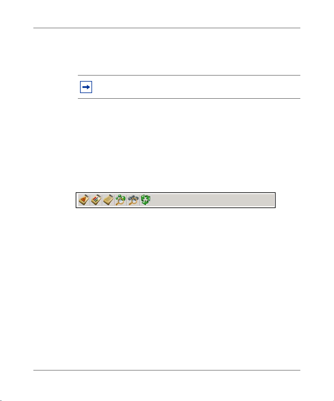
Figure 1 System Management Console tool bar icons
As shown in Figure 1 “System Management Console tool bar icons” on page 26,
the icons from left to right are:
•Alarm browser
•OM browser
• Log browser
• Logical view
•Physical view
• Refresh
NN42020-110 MCS 5100 Release 4.0 Standard 01.05 January 2008
Page 27

Alarm summary bar
This narrow horizontal bar, located below the toolbar, provides a concise systemwide summary of alarms for managed and monitored MCS network elements. The
background color of the alarm bar (green, yellow, orange, or red) indicates the
most severe alarm (none, minor, major, or critical) for the system. You can see the
total number of alarms for the system, as well as the number of alarms of each
severity level.
For information about alarms, see Alarm and Log Reference (NN42020-703).
Configuration view
The configuration view appears in the left pane of the System Management
Console. After you select a leaf node in the tree, a new window appears in the
application area in the right pane. You can collapse and expand the tree structure.
Information is organized into four sections:
• Network Data and Mtc: Use this section to define information such as IP
addresses, log report formats, OSS servers, and other data that does not
change often, but is reused during other configuration tasks. Enter the data in
this section to avoid retyping, and typing errors, during other configuration
tasks. Use this section to manage License keys for activating features.
• Servers: Use this section to configure servers and to monitor their hardware
and operating systems.
• Databases: Each Database has a folder. The folder contains software load and
configuration data so that the System Manager can connect to the database.
The System Manager can then distribute database connection information to
other network elements that need database access.
• Network Elements: Use this section to configure all managed and monitored
MCS network elements. Each network element type has a folder, and each
configured network element has a subfolder. After you select a network
element folder, the Alarm Browser, OM Browser, and Log Browser icons
become active for that network element. Use this section to make changes to
load deployment; configuration parameters; om, log, and accounting record
configuration. Use this section to perform maintenance tasks, such as start and
stop, for network elements.
Standard
27
System Management Console User Guide
Page 28
Standard
28
Work area
Locate the work area in the right pane of the System Management Console. After
you select a node from the configuration view pane, a window appears in the work
area. Windows in the work area display information about the selected node. The
information displayed in the work area is described with the respective
configuration view level in subsequent chapters. Some configuration view nodes
(Network Data and Mtc and Network Elements) have no associated windows.
Windows that appear in the work area have the following buttons.
Add: Use this button to add an element.
Edit: Use this button to make changes to an existing
element.
Delete: Use this button to remove an existing element.
Refresh: Use this button to update the information in the
window. For more information, see “Refreshing the work
area” on page 29.
Use the work area to view and manage multiple windows. Windows in the work
area can be moved, resized, or closed.
Refresh
Use the Refresh to update the information displayed in the work area of the
System Management Console. Refresh is available for all levels of the GUI tree,
except the logical nodes of Sites, Server, and Components.
The Refresh tool is not normally required because the System Management
Console updates automatically after an event occurs.
NN42020-110 MCS 5100 Release 4.0 Standard 01.05 January 2008
Page 29

Standard
Refreshing the work area
Use the following procedure to manually refresh the information displayed by
windows in the work area.
1 From the System Management Console GUI tree, select system, a site, a
server, a component, or service.
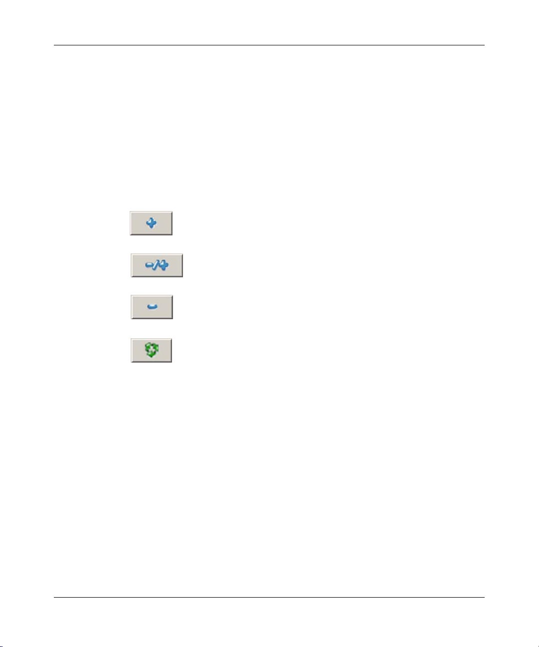
2 On the corresponding window that appears in the work area, click Refresh
Figure 2 Refresh button.
Refreshing the configuration, logical and physical views
The Refresh tool also refreshes the configuration, logical view, and physical view
windows of the System Management Console. After you click Refresh, the tool
queries the System Manager for the latest topology information and updates this
information on the System Management Console.
29
Views
To refresh the configuration, logical and physical views, select Too l s > R ef r e sh ,
or click the Refresh icon in the tool bar.
The trees in the configuration view and logical and physical view windows
collapse. The system updates the data to display the latest topology information.
The logical and physical view windows organize network elements by element
type and location, respectively. You can use these windows to diagnose fault
conditions.
System Management Console User Guide
Page 30

Standard
30
Logical view window
The logical view window provides a graphical view of the network elements (NE),
servers, and the logical databases. In this view, you cannot determine which
network elements are deployed on which servers.
Using this view, you can see the alarm conditions for all equipment for each NE
type. Select an NE instance to enable the alarm, log and OM browser buttons for
that element.
Open the logical view window by right-clicking on the alarm summary area, or by
clicking the logical view window icon in the icon toolbar.
Figure 3 Logical view icon
Physical view window
The physical view window provides a graphical view of the MCS system. The
elements are organized by site and server, and then by the network element
applications deployed on the server.
Using this view, you can view alarm conditions for all monitored equipment in
each site. Select a network element to enable the alarm, log, and OM browser
buttons for that element.
Open the physical view window by right-clicking on the alarm summary area, or
by clicking the physical view window icon in the icon toolbar.
NN42020-110 MCS 5100 Release 4.0 Standard 01.05 January 2008
Page 31

Figure 4 Physical view icon
Logical and physical view icons
For both view windows, a green dot indicates that the state of the network element
or server is clear. A yellow, orange, or red triangle indicates an alarm. If the bar
icon in the triangle is horizontal, it indicates a minor alarm. An angled bar
indicates a major alarm; a vertical bar indicates a critical alarm. A blue triangle
that does not have a bar indicates a warning.
An icon of a grey down arrow indicates unmanaged network elements and servers.
For a server, this icon indicates that the monitor for the server is not running. For a
network element or instance, the gray down arrow indicates that we do not have a
reported state from that element. The element is Offline, Configured, or
unavailable because of network issues.
Standard
31
System Management Console User Guide
Page 32

Standard
32
NN42020-110 MCS 5100 Release 4.0 Standard 01.05 January 2008
Page 33

Standard
Network Data configuration and management
The topics in this chapter include:
• “License key management” on page 33
• “Addresses” on page 35
• “SNMP Profiles” on page 38
• “Physical sites” on page 39
• “External nodes” on page 40
• “Informational elements” on page 41
• “Cipher suites” on page 42
• “Subnet masks” on page 43
• “Static routes” on page 43
• “OAM profiles” on page 44
33
License key management
Updating and querying license keys requires an administrative role with
LicenseKeyService privilege.
The following list provides a brief description of each tab displayed on the
Licensekey window.
• Features: This tab shows licenseable units that can be enabled or disabled and
that also have a limit restricting their use.
• Feature States: This tab shows licenseable units that can only be enabled or
disabled. They do not have limits associated with their use.
• Version info: This tab shows the version of the license key (this may differ
from the software version during upgrade). It shows the date and time that the
licensekey was generated as well as the id of the generator and the licensekey
comments.
System Management Console User Guide
Page 34

Standard
34
• Licenseable Units: This tab shows licenseable units that are always enabled
and have a limit restricting their use.
• Network Elements: This tab shows the network elements that do not have
ports or endpoints associated with them in the licensekey. The tab shows the
number of these network elements that can be configured in the system as
well as the type and number of configured network elements. .
Note: The Network Elements tab does not show information about
servers. A redundant Session Manager or System Manager pair is one
network element. The Servers Licensed value is the number of network
elements allowed by the license. The Current Server Usage value is the
number of network elements currently used.
• Network Elements with Ports: This tab shows the network elements that have
ports but do not have endpoints associated with them in the license key. This
tab shows the number of these network elements that can be configured in the
system and the number of ports that can be used. This tab also shows the
current number of configured network elements of each type.
• Network Elements with Ports and EndPoints: This tab shows the network
elements that have ports and endpoints associated with them in the licensekey.
The tab shows the number of these network elements that can be configured in
the system and the number of ports and endpoints that can be used. It also
shows the current number of configured network elements of each type.
Licence key updates
Updates can be performed for a current release and any subsequent maintenance
releases only. New major releases (for example, 3.0 to 4.0) require a new license
key.
Updates to a license key can only increase system capabilities. For example,
licenses can be updated to allow capabilities for more subscribers, not fewer.
Network elements can register their interest in particular key codes within the
license key. After you update the license key, the key codes automatically push
down to all elements with a registered interest.
NN42020-110 MCS 5100 Release 4.0 Standard 01.05 January 2008
Page 35

Standard
Updating a license key
Administrators update license keys by selecting Network Data and Mtc >
Licensekey in the configuration view of the System Management Console. The
License Key can be updated dynamically without any disruption of service. The
update rolls back if the License Key update procedure fails.
1 In the System Management Console, from the configuration view, select
Network Data and Mtc > Licensekey.
2 Click the Edit button at the Licensekey window.
The Select License key File dialog box opens.
3 Navigate to the license key file that is on the local computer, select it, and
click Open.
A confirmation message appears after the license key is successfully saved into
the database. If the update fails, the License Key update rolls back.
35
Querying a license key
To query license keys, navigate the tabs on the Licensekey window. The licensed
limits and current usage appear in the display.
Addresses
To avoid configuration errors related to entering IP addresses inaccurately, enter
all the IP addresses for all managed and monitored network elements at the same
time, in the Addresses window.
To open the Addresses window, select Network Data and Mtc > Addresses from
the navigation view. To perform operations at the Addresses window, you must
have IPAddressService privileges.
System Management Console User Guide
Page 36

Standard
36
Before you add a server to the MCS network, you must add the server IP address,
in the Addresses window and associate a Logical Name with that IP Address. You
cannot delete an IP address if a third-party Trusted Device, Gateway, Operations
Support System (OSS) Server, or server that hosts an MCS network element is
configured against the Logical Name for that IP address. You can change the IP
address, but services are interrupted.
Configuring an IP address
Use the following procedure to enter Addresses for servers and network elements.
Note: Editing an entry and changing the IP address disrupts service for
the network element and all services for the network elements deployed
on the server
1 In the System Management Console navigation pane, select Network Data
and Mtc >Addresses.
2 In the Addresses window, click Add or select an entry and click Edit.
3 Enter the configuration data.
Both fields, Logical Name and IP Address, must be unique values.
4 Click Apply.
Deleting an address
Note: Before deleting an address, you must delete the network element
or server that uses that IP address.
1 In the System Management Console, in the Addresses window, select an
entry.
2 Click Delete.
3 Click Ye s to confirm the delete.
NN42020-110 MCS 5100 Release 4.0 Standard 01.05 January 2008
Page 37

Component re-IP
The MCS software components belong to three broad categories based on their
interactions with the System Manager:
• Managed: The System Manager manages the core MCS components, such as
the Accounting Manager, IP Client Manager, Database, Provisioning
Manager, and Session Manager.
• Monitored: Some components are monitored, but not managed, by the System
Manager. These components can be running on a server that does not support
re-IP.
• Informational: Some components are neither managed nor monitored by the
System Manager. The System Manager has access to only the IP addresses of
these components.
The System Manager maintains an address table, which is a central record of all
IP addresses in the network. Any software component that falls outside the scope
of Managed, Monitored or Informational does not appear in the address table, and
is not covered by this feature.
Standard
37
Administrators with sufficient privileges can add to, edit, or delete entries in the
address table by using a script, or by using the System Management Console. The
system displays a confirmation message before it applies the changes. After you
confirm your changes, the system applies them to all MCS components that are
managed by the System Manager. See “Editing the address table” on page 37.
The Complete re-IP feature adds two services:
• The Informational Element service provides type information, and replaces
the Third Party Trusted Devices configuration service.
• The External Nodes configuration service allows you to add multiple
Informational Elements with the same IP address and different ports.
To locate these services, in the System Management Console, in the configuration
view, expand Network Data and Mtc. For a practical application, see “Trusted
node configuration” on page 112.
Editing the address table
1 Start the System Management Console.
System Management Console User Guide
Page 38

Standard
38
2 Select Network Data and Mtc > Addresses.
3 Select and modify or delete an address, or add an address, and click Apply.
4 Confirm the changes.
SNMP Profiles
The System Manager uses simple network management protocol (SNMP) profiles
to access (query) SNMP agents on network elements. You can access or create
SNMP Profiles by selecting Network Data and Mtc > SNMP Profiles from the
navigation pane. To perform SNMP profile configuration, you must have
SnmpProfileService privileges.
SNMP profiles are created to configure consistent SNMP parameters that the
System Manager uses to monitor the condition of the operating system and server
hardware for the managed and monitored MCS network elements.
You create a profile that has a port number and read and write community strings
that match the SNMP daemon settings on a server. After you create the profile and
server configuration begins, you associate the profile with a server so that the
System Manager can monitor the server.
After you create an SNMP Profile, you cannot edit it. If administrators want to
change the SNMP community string, or any other parameter, to increase security,
they must
• configure a new SNMP profile as described in “Configuring an SNMP
profile” on page 38
• assign the new SNMP profile to each server as described in “Server
configuration” on page 56
To increase SNMP security, administrators can be assigned an administrative role
that does not have SnmpProfileServices privilege.
Configuring an SNMP profile
Use the following procedure to create a new SNMP profile. Afterward, use the
System Management Console to associate the new SNMP profile with the servers
that you want to use the profile.
NN42020-110 MCS 5100 Release 4.0 Standard 01.05 January 2008
Page 39

1 Select Network Data and Mtc > SNMP Profiles from the navigation pane.
2 Click Add or select an entry and click Edit.
3 In the Server SNMP Profiles dialog box, enter the configuration data.
4 Click Apply.
Deleting an SNMP profile.
Note: Before deleting an SNMP Profile, edit any servers that use the
profile and configure the servers to use a different SNMP Profile.
1 Select an entry from the SNMP Profiles window.
2 Click Delete.
3 Click OK to confirm the delete.
Standard
39
Physical sites
To manage site information you must have PhysicalSiteService privileges. After
you select Network Data and Mtc > Physical Sites in the configuration view pane,
the work area displays a window with the following site-level information:
• Site Name: a name configured for this site by the administrator
• Zone: the Universal Transverse Mercator (UTM) zone for the site
• Easting: the UTM Easting coordinate for the site
• Northing: the UTM Northing coordinate for the site
Configuring a site
1 Select Network Data and Mtc > Physical Sites from the navigation pane.
2 Click Add or select an entry and click Edit.
System Management Console User Guide
Page 40

Standard
40
3 In the Site dialog box, enter the configuration data.
Table 2 Site configuration
Field Value Description
Site name alphanumeric (1-20
Zone alphanumeric (1-3
Easting integer (1-1 000 000 digits) Easting of the site
Northing integer (1-7 digits) Northing of the site
4 Click Apply.
Deleting a site
Note: Administrators must delete all the servers and network elements of
a site, before deleting the site itself.
1 Select the site from the Physical Sites window.
2 Click Delete.
3 Click Ye s to confirm the delete.
characters)
characters)
a unique name identifying
the site
UTM zone location of this
site
For numbers greater than
1 100, do not enter spaces.
External nodes
To perform operations on this data, you must have InfoElementService privileges.
Configuring an external node
1 In the System Management Console, from the navigation pane, select
Network Data and Mtc > External Nodes.
2 Click Add or select an entry and click Edit.
NN42020-110 MCS 5100 Release 4.0 Standard 01.05 January 2008
Page 41

3 In the Add Trusted Device dialog box, enter the configuration data:
• Name—Enter the name of the device, such as MAS110.
• DeviceAddress—Use the drop-down list to select the address of the
device.
4 Click Apply.
Deleting an external node
1 Select an entry on the External Nodes window.
2 Click Delete.
3 Click Ye s to confirm the delete.
Informational elements
To configure this data you must have InfoElementService privileges.
Standard
41
Configuring an informational element
1 In the System Management Console, from the navigation pane, select
Network Data and Mtc > Informational Elements.
2 Click Add or select an entry and click Edit.
3 In the Add Informational Element (IE) dialog box, enter the configuration
data:
• ShortName: the name of the device, such as MAS110
• LongName: the long name of the device (same as the description of a
long name field for a Network Element)
• Node: external node configured
• Port: an integer, 0 to 65 534
• Trusted : specifies whether the informational element is trusted
The IE is trusted for SIP communications only, not for any other protocol.
• ExemptDoSProtection: specifies whether the IE is exempt from Denial
of Service Protection
• Type: Informational Element type
System Management Console User Guide
Page 42

Standard
42
• SIP Transport: SIP Transport type
4 Click Apply.
Deleting an informational element
1 Select an entry on the Informational Element window.
2 Click Delete.
3 Click Ye s to confirm the delete.
Cipher suites
Use cipher suites to configure the encryption used for communication between the
System Manager and the MCS network elements. To configure cipher suites, you
must have CipherSuiteService privileges. You do not add cipher suites to the MCS
system; you enable or disable them.
After you apply a new list of cipher suites to the network, you stop all
configuration streams, log streams, alarm streams, OM streams, and accounting
streams between network elements. After the streams resume, they are secured
with the newly applied cipher suites. You do not need to restart the network
element instances. Two of the cipher suites cannot be disabled. These two cipher
suites ensure that network element communication can always continue over a
common negotiated cipher suite.
The normal alarms associated with communication for the particular subsystem
are logged while the connections are reestablished. The alarms clear automatically
after normal communication resumes.
Configuring cipher suite usage
1 In the System Management Console, from the navigation pane, select
Network Data and Mtc > Cipher Suites.
2 In the Cipher Suites window, select an entry for the cipher suite to enable or
disable, and click Enable or Disable.
3 Click Apply.
NN42020-110 MCS 5100 Release 4.0 Standard 01.05 January 2008
Page 43

Subnet masks
Subnet Masks are only required for the RTP Media Portal (renamed to Border
Control Point 7000 Series). Subnet Masks provide greater flexibility in defining
IP addresses for the Media Portal Service Cluster and define the scope of an
address space. This information is used to scope the extent of the service-planes in
the “Media Portal Cluster” data structure and to define static routes in separate
datafill.
Configuring a subnet mask
1 In the System Management Console, from the navigation pane, Select
Network Data and Mtc > Media Portal Data > Subnet Masks.
2 Click Add or select an entry and click Edit.
3 In the Add Subnet Masks dialog box, enter the configuration data.
4 Click Apply.
Standard
43
Deleting a subnet mask
1 Select an entry from the Subnet Masks window.
2 Click Delete.
3 Click Ye s to confirm the delete.
Static routes
Static Routes define the special routing considerations that must be employed to
access remote network nodes and network resources. This section is required only
for the Border Control Point. The Static Routes entity contains the static routes
entries that must be populated on the BladeCenter T-based BCP as the BCP comes
into service.
This section applies only to the BladeCenter T-based BCP. For more information,
see “Configuring a static route” on page 44.
System Management Console User Guide
Page 44

Standard
44
Configuring a static route
Use the following procedure to add or edit a Static Route entry.
1 In the System Management Console, from the navigation pane, select
Network Data and Mtc > Media Portal Data > Static Routes.
2 Click Add or select an entry and click Edit.
3 In the Add Static Routes dialog box, enter the configuration data.
4 In the Add Static Routes dialog box, provide a Static Route Name to uniquely
identify this static route.
5 From the Gateway drop-down list, select the gateway that can route to the
relevant remote network.
6 From the Destination Network (External Node) drop-down list, select the
remote network.
7 From the Destination Subnet Mask drop-down list, select the network mask to
specify the extent of the remote network.
8 Click Apply.
Deleting a static route
1 Select an entry from the Static Routes window.
2 Click Delete.
3 Click Ye s to confirm the delete.
OAM profiles
The OAM Profiles folder of the configuration view organizes operations support
system (OSS) information and log, operational measurement (OM), and
information about accounting record format.
NN42020-110 MCS 5100 Release 4.0 Standard 01.05 January 2008
Page 45

OSS server
Use the OSS server to send alarms, logs, OMs, and accounting record information
to a northbound OSS, which is the OSS destination. Open the OSS server window
by selecting Network Data and Mtc > OAM Profiles > OSS Server from the
configuration view of the System Management Console.
Before configuring an OSS server, you must add the IP address for the server in
the Addresses window. To perform operations in the OSS Server window, you
must have OssProfileService privileges.
After you create an OSS Server profile, you associated it with a Name and an
Address. After you create the profile, you can associate it with FTP Push profiles
and SNMP Manager profiles.
Record format
The record format folder organizes the formatting of logs, OMs, and accounting
record formats preferred by operating company personnel.
Standard
45
Configuring a log record format
To configure log record formats, you must have FPOssProfileService privileges.
1 Select Network Data> OAM Profiles > Record Format > Log Record
Format from the configuration view.
2 Click Add or select an entry and click Edit.
System Management Console User Guide
Page 46

Standard
46
3 In the Log Record Format dialog box, enter the configuration data.
Table 3 Log record format configuration
Field Value Description
Name string, 1 to 32
characters
Type STD, MCP, or SCC2 STD is Nortel standard format.
Ecore true or false If the log format is STD or SCC2 and this
This field identifies this profile. This value is
used to create a Format Path for log reports,
for example, MCPO, std., or scc2.
MCP is an extension of STD and offers log
identifiers that are longer than four characters,
as well as long lines.
SCC2 is a Telcordia standard format.
parameter is configured to true, the log header
information includes a field that identifies the
originating stream. For example, the
originating stream could be identified as a
network element instance.
4 Click Apply.
Configuring an OM record format
To configure OM record formats, you must have FPOssProfileService privileges.
1 In the System Management Console, from the configuration view, select
Network Data and Mtc > OAM Profiles > Record Format > OM Record
Format.
2 Click Add on the OM Record Format window.
3 In the Add OM Record Format dialog box, specify a name for the format,
such as comma-separated value (CSV).
4 Click Apply.
Configuring an Accounting record format
To configure accounting record formats, you must have AMOssProfileService
privileges.
NN42020-110 MCS 5100 Release 4.0 Standard 01.05 January 2008
Page 47

1 In the System Management Console, from the configuration view, select
2 Click Add or select an entry and click Edit.
3 In the Accounting Data Format dialog box, enter a Name for the format, such
4 Select MCPV3 or MCPV4 for the Type.
5 Click Apply.
File Type
The File Type folder contains configuration data for all OSS file types, such as
FLATFILE, MCP3IPDRXML, or MCP4IPDRXML. FLATFILE is an ASCII file
type and lines are terminated only by a carriage return. MCP3IPDRXML and
MCP4IPDRXML formats are for accounting record formats. To perform
operations with File Type data, you must have OssProfileService privileges.
Standard
47
Network Data and Mtc > OAM Profiles > Record Format > Accounting
Record Format.
as acct.
Adding a file type
1 In the System Management Console, from the configuration view, select
Network Data and Mtc > Profiles > File Type.
2 Click Add on the File Type window.
The Edit button is available, but you cannot modify existing File Type
configuration data. The Add File Type dialog box opens.
3 In the Add File Type dialog box, enter the configuration data.
Table 4 File type configuration
Field Value Description
Name string, 1 to 32
characters
Ty p e FL AT F I LE ,
MCP3IPDRXML,
MCP4IPDRXML
This value identifies this file type and is needed to
configure the format path.
FLATFILE is an ASCII format with lines terminated
by a carriage return.
MCP3IPDRXML and MCP4IPDRXML are
accounting record formats that use XML to record
Internet protocol detail record (IPDR) information.
System Management Console User Guide
Page 48

Standard
48
Table 4 File type configuration
Field Value Description
Rotation rule string This creates a rule for closing active files and
opening new files. Rules are based on time
(interval or a specific hour and minute) and
optionally by size (in kilobytes):
EVERY n | AT hh:mm AM|PM OR SIZE m
EVERY n - This keyword indicates to rotate a file at
a specific interval in minutes, such as 60.
AT hh:mm AM|PM - This keyword indicates to
rotate a file at a specific time each day, such as
06:00 AM.
OR SIZE m - This keyword modifies the rule so
that a file can be rotated before the interval expires
or before the specified time if the file reaches the
size specified in kilobytes, for example, SIZE 200.
Retention in
day
Retention
enabled
Compression true or false This value indicates if the System Manager must
integer, 1 to 7 This value indicates the number of days to retain
the files.
true or false This value indicates if files must be retained, the
number of days specified in Retention in day, or if
the Retention in day value must be ignored and all
files older than seven days must be deleted.
record the files in a compressed format.
4 Click Apply.
Format path
The Format Path folder organizes configuration data for log, OM, and accounting
records. In this folder, configuration data is entered to associate the format
configured in Record Format with a File Type to create a Format Path. An
administrative role with FPOssProfileService privilege is needed to work with the
log and OM formats.
Configuring a log format path
1 In the System Management Console, from the configuration view, select
Network Data and Mtc > OAM Profiles > Format Path > Log Format
Path.
2 Click Add or select an entry and click Edit.
NN42020-110 MCS 5100 Release 4.0 Standard 01.05 January 2008
Page 49

Standard
3 In the Log Format Path Profile dialog box, enter a name, and then select a
Data Format and File Type.
The options for Data Format and File Type depend on information previously
entered for Log Record Format and File Type. For example, enter the name
mcp-file if the Data Format is mcp and the File Type is file.
4 Click Apply.
The Log Format Path Profile dialog box closes and an entry appears in the
Log Format Path window. Use this data to configure the Standard Log Stream
for the System Manager or a Fault Performance Manager.
Configuring an OM format path
1 In the System Management Console, from the configuration view, select
Network Data and Mtc > OAM Profiles > Format Path > OM Format
Path.
2 Click Add or select an entry and click Edit.
3 In the OM Format Path Profile dialog box, enter a name, and then select a
Data Format and File Type.
49
Options for Data Format and File Type depend on previous configuration
data. For example, enter a name of csv-file if the Data Format is CSV and the
File Type is file.
4 Click Apply.
The OM Format Path Profile dialog box closes and an entry appears in the
OM Format Path window. Use this data to configure the Standard OM Stream
for the System Manager or a Fault Performance Manager.
Configuring an accounting format path
To configure an accounting format path, you must have AMOssProfileService
privileges.
1 In the System Management Console, from the configuration view, select
Network Data and Mtc > OAM Profiles > Format Path > Accounting
Format Path.
2 Click Add or select an entry and click Edit.
System Management Console User Guide
Page 50

Standard
50
3 In the Accounting Format Path Profile dialog box, enter a name, and then
select a Data Format and File Type.
Options for Data Format and File Type depend on previous configuration
data. For example, enter a name of mcp4-ipdr4 if the Data Format is mcp4 and
the File Type is ipdr4.
4 Click Apply.
The Accounting Format Path Profile dialog box closes and an entry appears in
the Accounting Format Path window. Use this data to configure the Standard
Accounting Stream for an Accounting Manager.
FTP Push
The FTP Push section of the configuration view organizes profiles for transferring
logs, OMs, and accounting records from the System Manager or FaultPerformance Manager to an OSS server. Before you create an FTP Push profile,
you must configure the OSS Server.
After you create an FTP Push profile, you can configure the System Manager and
Fault-Performance Manager network elements to use the FTP Push profile for
transmitting logs and OMs by associating the FTP Push profile with an FTP Push
Log Stream or an FTP Push OM Stream.
You can configure Accounting Manager network elements to use the FTP Push
profile for transmitting accounting records by associating the FTP Push profile
with an FTP Push Accounting Stream.
To work with FTP Push, you must have OssProfileService privileges.
Creating an FTP Push profile
1 In the System Management Console, from the configuration view, select
Network Data and Mtc > OAM Profiles > FTP Push.
2 Click Add or select an entry and click Edit.
NN42020-110 MCS 5100 Release 4.0 Standard 01.05 January 2008
Page 51

3 In the FTP Push Profile dialog box, enter the configuration data.
Table 5 FTP Push profile configuration
Field Value Description
Standard
51
Name string, 1 to 32
characters
Server drop-down menu
selection
Root Directory string Enter the destination directory on the
User ID string Enter a valid user account for the OSS
Password string Enter the password for the account on
Confirm Password string Repeat the password for the account on
Enabled checkbox Click to enable/disable FTP Push.
Enter a name to identify this profile. This
value is needed to associate this profile
with an FTP Push log, OM, or
accounting stream.
Select a configured OSS Server from the
drop-down menu. An OSS Server must
be configured before performing this
procedure.
OSS server to place records. This
directory must already exist on the OSS
server. The transferred files are
organized further by directory structure.
See Pushed file directory structure.
server.
the OSS server.
the OSS server.
4 Click Apply.
Pushed file directory structure
During the transfer of records, the System Manager, Fault-Performance Manager,
or Accounting Manager opens an FTP session to the root directory on the OSS
server (as specified by the Root Directory parameter). The file and directory
structure organizes the records on the OSS server:
<Root Directory>/oss/<stream>/MCP_9.1/<ne>/<monitored_nes>
• Root Directory—This is the value defined for the Root Directory parameter.
• stream—This value specifies the type stream: log, om, or acct.
System Management Console User Guide
Page 52

Standard
52
• ne—This identifies the network element instance that gathered the data, such
as SM_x, FPM_x, or AM_x.
• monitored_nes—Directories are created for each network element instance
that is monitored by this System Manager, Fault-Performance Manager, or
Accounting Manager.
For example, if System Manager instance 0 (SM_0) is responsible for collecting
logs from Accounting Manager instance 0 (AM_0), and the records are
transferred, the log files are placed in the following location:
.../oss/log/MCP_9.1/SM_0/AM_0/...
SNMP Manager
Network administrators can integrate alarms generated by MCS-managed network
elements into the current Network Management Layer (NML) manager.
Alarm-generating events generate reports that go to the SNMP (Simple Network
Management Protocol) Manager registered with the system. These event reports
are called traps. To perform operations with SNMP Manager data you must have
SnmpProfileService privileges.
To start forwarding traps to an existing Network Management Layer (NML)
manager, complete the following procedure and then configure the System
Manager and all Fault-Performance Managers to use this SNMP Manager profile.
Adding an SNMP manager
1 In the System Management Console, from the configuration view, select
Network Data and Mtc > OAM Profiles > SNMP Manager.
2 Click Add or select an entry and click Edit.
NN42020-110 MCS 5100 Release 4.0 Standard 01.05 January 2008
Page 53

3 In the Add SNMP Manager dialog box, enter the configuration data.
Table 6 SNMP manager configuration
Field Value Description
Standard
53
Name string, 1 to 32
characters
Community string This field indicates the community string that
Server drop-down Select a configured OSS server.
Trap Port integer This field identifies which port the traps should
This field identifies the SNMP Manager profile.
This value is used to associate this SNMP
Manager profile with the System Manager or a
Fault-Performance Manager.
the SNMP trap daemon on the OSS server is
configured to accept.
be sent to. This value must match the
configuration of the SNMP daemon on the OSS
server.
4 Click Apply.
System Management Console User Guide
Page 54

Standard
54
NN42020-110 MCS 5100 Release 4.0 Standard 01.05 January 2008
Page 55

Standard
Server configuration and maintenance
The topics in this chapter include:
• “Server configuration and management overview” on page 55
• “Server configuration” on page 56
• “Server performance statistics” on page 58
Server configuration and management overview
The addition of new servers and server configuration typically occurs during
installation and commissioning. The number, type, and redundancy of servers
depends on the specific network configuration.
Servers host the following network element applications:
• System Manager
• Database Manager
• Border Control Point (formerly known as RTP Media Portal)
• Fault Performance Managers
• Accounting Managers
• Session Managers
• Provisioning Managers
• Personal Agent Managers
• IP Client Managers
• UFTP Servers
55
Note: These network element applications are deployed on managed
servers. However, many network element applications are coresident on a
single server. For example, a System Manager server can host one
instance of the System Manager and one instance of an
Accounting Manager.
System Management Console User Guide
Page 56

Standard
56
Server configuration
To perform operations with server data, you must have PhysicalServerService,
PhysicalSiteService, IPAdddressService, and SnmpProfileService privileges.
Configuring a server.
Note: If you modify an operational server, you affect services deployed
on that server.
1 In the System Management Console, from the configuration view, select
Servers.
2 Click Add or select an entry and click Edit.
3 In the Server dialog box, enter the configuration data.
Table 7 Server configuration data
Field Value Description
Server Name string, 1 to 6
characters
Long Server Name string, 1 to 32
characters
Physical Site drop-down Select the location of the server.
Interface 1 drop-down Select the Logical Name of the IP address for
Interface 2 (mgmt) drop-down This optional field is used to configure a
LOM Server drop-down This optional field specifies the Lights Out
LOM Server Port port number This optional field specifies the port number
This field indicates the name of the server, for
example, EMS1. This value is used to
associate the network element application
with the server.
This field indicates the long name of the
server, for example, EMS1Server.
this server.
management LAN. If configured, all
northbound OAM feeds are sent over this
interface.
Management server for a server.
for the Lights Out Management server.
NN42020-110 MCS 5100 Release 4.0 Standard 01.05 January 2008
Page 57

Standard
Table 7 Server configuration data
Field Value Description
Operating System drop-down This field is used for SNMP polling. If this field
is configured to windows, memory information
will not be polled from the server. This field
must not be configured to windows. This field
is also used to determine file paths.
Server Type drop-down Use this field to specify the server type:
SNMP Profile drop-down Select the name of an SNMP profile. Ensure
Host Name string, 1 to 32
characters
Bladeserver, CC3310, or Other.
that the operating system SNMP daemon is
configured to match the defined SNMP profile.
This parameter identifies the hostname of the
server.
4 Click Apply.
Use the new data to configure a network element instance.
57
Deleting a server
You must delete all of the hosted network elements that are deployed on the server
before you delete the server. If you attempt to delete a server that has services
deployed on it, the system rejects the request and indicates that the server is
associated with NEInstanceData.
1 In the System Management Console, from the configuration view, select
Servers.
2 From the Servers window, select the <server> entry.
3 Click Delete.
4 Click Ye s to confirm the delete.
System Management Console User Guide
Page 58

Standard
58
Server performance statistics
After you enter server configuration data through the System Management
Console, one of the parameters is SNMP Profile. To monitor the performance
statistics for the server, you must use the System Management Console to start the
server monitor. Before the monitor starts, a grey down arrow icon is associated
with the server in the Logical and Physical View windows. After the monitor
starts, a green, yellow, orange, or red dot indicates the status of the server
hardware.
Monitoring a server
1 In the System Management Console, from the configuration view, select
Servers > <server_name> > Monitor.
The Monitor window for the server appears in the work area. If the monitor is
not running, the status line at the bottom left of the monitor window indicates
“The server monitor is not running.”
2 Click Start Monitor to collect statistics for the server.
The status line changes to indicate “The server monitor is running.”
The system stores these statistics on a disk, on the server that hosts the System
Manager. To view these records, configure an FTP Push job, and then configure
the System Manager FTP Push OM Stream to use the FTP Push job.
NN42020-110 MCS 5100 Release 4.0 Standard 01.05 January 2008
Page 59

Configuring server alarm thresholds
To configure server alarm thresholds you must have ServerMonitorConfigService
privileges.
Note: If the monitor is running and no statistics appear on the monitor
window, check the Logical or Physical View window for a major
SRVR101 alarm against the server. This alarm indicates that the SNMP
daemon on the server is not responding. Verify that the server is running,
and then verify the configuration data related to the SNMP Profile
associated with the server.
You can configure thresholds for CPU, memory, disk, and interface usage from
the Monitor window by clicking Configure Thresholds.
1 In the System Management Console, from the configuration view, select
Servers > <server_name> > Monitor.
Standard
59
2 In the Server Monitor Alarm Threshold Configuration window, modify the
thresholds by changing the threshold values, or by enabling and disabling the
alarm thresholds.
Enter new values to configure different thresholds. To remove alarms for
exceeding thresholds, deselect the check box next to each item.
3 Click OK.
System Management Console User Guide
Page 60

Standard
60
NN42020-110 MCS 5100 Release 4.0 Standard 01.05 January 2008
Page 61

Standard
Database configuration and management
The topics in this chapter include:
• “Viewing the database monitor status” on page 61
• “Configuring resource thresholds” on page 62
You configure and deploy the database when you install and commission it. After
you commission the database, the only database operation you perform from the
System Management Console is monitoring the database.
Viewing the database monitor status
The database monitor indicates the capacity, disk space used, and status of the
database. To perform this procedure, you must have DBMonitorService
privileges.
61
1 In the System Management Console, from the configuration view, select
Database > mcpdb > Monitor.
2 In the mcpdb Monitor window, select instance 0 or 1and click Monitor.
The mcpdb_x Database Instance Monitor window opens. The Replication tab
appears in replicated database configurations only.
3 Check the status line at the bottom of the Monitor window.
The status should indicate “The database instance monitor is running.”
4 If the database instance monitor is not running, click Start Monitor.
System Management Console User Guide
Page 62

Standard
62
Configuring resource thresholds
To perform this procedure you must have DBMonitorConfigService privileges.
Use the following procedure to configure thresholds for the database monitor
control, after a DBMN401 alarms occur.
1 In the System Management Console, from the configuration view, select
Database > mcpdb > Monitor.
2 In the mcpdb_x Database Instance Monitor window, click
Configure Thresholds.
The DB Monitor Alarm Threshold Configuration window appears. The
default thresholds are 80 for Minor, 90 for Major, and 100 for Critical.
3 Select each threshold to enable for alarm, and configure a threshold.
4 Click OK.
NN42020-110 MCS 5100 Release 4.0 Standard 01.05 January 2008
Page 63

Standard
Network element configuration and management
The topics in this chapter include:
• “Network element configuration overview” on page 63
• “Network element configuration” on page 63
• “Network element software updates” on page 69
• “Network element management” on page 71
• “MCS system without a BCP” on page 73
• “MAS OAM fault integration” on page 74
• “IPCM profile” on page 75
Network element configuration overview
Administrators add, configure, and manage most network elements by using the
System Management Console. For network element specific details, see the
individual network element guides. For a list of network element documents see
“Related publications” on page 17.
63
Add the System Manager and Database Manager (Databases in the configuration
view) manually, without the use of the System Management Console. However,
you can use the System Management Console to monitor both.
Network element configuration
You can add, configure, and manage network elements, by using the System
Management Console. Add the System Manager network element manually. The
System Manager must be operational before administrators can connect with the
System Management Console.
System Management Console User Guide
Page 64

Standard
64
The network elements you can add to a specific server depend on the system
architecture and operational requirements. Refer to the individual network
element guides for specific details related to network element configuration.
The following procedures are generic and do not apply to any specific network
element application. For specific configuration details and service property
descriptions, see the individual network element guides. For a list of the related
network element guides, see “Related publications” on page 17.
Adding a network element
To add a network element you must have NEService privileges.
1 In the System Management Console, from the configuration view, select
Network Elements > <ne_type>.
A window for the network element type appears in the work area. Existing
network elements, of this type, are indicated by a row in the window.
2 In the network element window, click Add.
3 In the Add window, enter the configuration data.
Different network element types require different configuration data. For
configuration issues and property descriptions, see the network elementspecific guides. For help with property descriptions, move the pointer over the
property name.
4 Click Apply.
The Add window closes and an entry appears in the network element type
window. The network element appears in the configuration view, but it does
not have any servers or software associated with it yet.
5 In the configuration view, expand the network element so that the newly
configured element is visible, and select Instance.
The network element instance window appears in the work area.
6 Click Add to add an instance of this network element and associate the
instance with a server.
NN42020-110 MCS 5100 Release 4.0 Standard 01.05 January 2008
Page 65

Standard
7 In the Add Instance dialog box, use the drop-down menus to associate a
server, a software load, and an engineering profile with the instance.
The engineering profile controls the initial size of the Java Virtual Machine
and establishes engineering parameters appropriate for the hardware
capabilities of the server.
8 Click Apply on the add instance dialog box.
9 If the network element offers fault tolerance, and the network architecture is
designed for a redundant unit, repeat steps 6 and 7 for the second unit.
10 From the configuration view, select NE Maintenance for the newly created
network element.
The Maintenance window for the network element appears in the work area.
The state is CONFIGURED and the network element does not provide service
yet.
11 In the Maintenance window, select an instance and click Deploy.
Software transfers from the System Manager to the server associated with the
selected network element instance. The instance changes from
CONFIGURED to DEPLOYING. After deployment is complete, the instance
changes to OFFLINE.
65
12 If the network element is fault tolerant, select the other instance and click
Deploy again.
13 Select an instance and click Start on the Maintenance window.
The instance completes the following state changes:
• OFFLINE to STARTING: Clicking the Start button causes this transition.
• STARTING to CONNECTED: The instance has communication with the
System Manager.
• CONNECTED to INITIALIZING: Bootstrapping is complete and
subsystems on the instance are initializing.
• INITALIZING to STANDBY: If the network element is fault tolerant, and
the other instance is active, this instance remains in STANDBY until a
switch of activity.
• STANDBY to ACTIVATING: This instance must become the active
instance.
• ACTIVATING to ACTIVE: This instance is now providing service.
System Management Console User Guide
Page 66

Standard
66
The time required to complete the installation and activation depends on the
network element type and the hosting server.
Network element modification
Network elements can be modified in several ways:
• modify a whole network element: Use this option to modify the base port of a
network element application, to associate a different Fault-Performance
Manager with the network element, and to modify many options that are
specific to each network element type.
• modify a network element instance: Engineering parameters for each network
element instance can be altered.
• modify Configuration Parameters: Use this option to modify operating
parameters that can be modified while the network element is in service. The
changes apply to all network element instances of the network element.
Note: Installation of a network element on a server can generate a
threshold alarm that indicates high CPU usage. The alarm clears after the
installation is complete.
Modifying a whole network element
The properties for each network element type differ. Refer to the specific network
element documentation for information about the properties. To perform this
procedure you must have NEService privileges.
1 In the System Management Console, from the configuration view, select
Network Elements > <ne_type>.
A window for the network element type appears in the work area.
2 Select the entry for the network element to modify and click Edit.
3 In the Edit dialog box, modify the configuration data.
4 Click Apply.
A warning dialog box opens if other network elements need to be restarted as
a result of the configuration change. Otherwise, the Edit dialog box closes and
the system applies the data change to all instances of the network element
immediately.
NN42020-110 MCS 5100 Release 4.0 Standard 01.05 January 2008
Page 67

Standard
67
Modifying a network element instance.
Caution: Before performing this procedure, contact your next level of
support. Engineering parameters must not be modified in the field.
Modifying the engineering parameters for a network element instance can
reduce the performance and services of the network element.
Any changes require a manual restart of the network element instance to take
effect, and the changes apply to only a single network element instance; for
redundant network elements, the change must be made to other network element
instances too. To perform this procedure you must have NEInstanceService and
EngParmService privileges.
The only appropriate modification to an NE Instance is to the load during an
upgrade, or to move the NE Instance to a different server.
1 From the configuration view, select Network Elements > <ne_type> > <ne>
> Instance.
The Instance window appears in the work area.
2 Select the network element instance to modify from the Instance window and
click Edit.
The Edit Instance dialog box appears.
3 Click Advanced on the Edit Instance dialog box.
The Edit Eng Parms window appears in the work area. Engineering
parameters are organized by Parm Group.
4 From the drop-down menu, select the Parm Group to modify.
The engineering parameters appear on the Instance Eng Parms window.
5 From the Instance Eng Parms window, select the engineering parameter to
modify, and click Edit.
The Edit Eng Parms dialog box appears.
6 Enter a new value for the engineering parameter.
For help, move the pointer over the parameter.
7 Click Apply.
System Management Console User Guide
Page 68

Standard
68
8 Click OK to confirm the warning.
You must manually restart for the changes to take effect. For information on
how to perform a manual restart, see the documentation for the particular
network element type.
Modifying configuration parameters
Every network element type has some configurable operating parameters. Which
parameters can be configured, depends on the network element type. To perform
this procedure you must have ConfigParmService privileges.
1 In the System Management Console, from the configuration view, select
Network Elements > <ne_type> > <ne> > Configuration Parameters.
2 In the Config Parms window, from the drop-down list, select a parameter
group.
3 Select the parameter to modify and click Edit.
4 In the Edit Config Parms dialog box, enter a new value for the configuration
parameter.
5 Click Apply.
The system validates the new value. If the value is valid, the Edit Config Parm
window closes and the configuration parameter updates.
Deleting a network element
Caution: Administrators can delete a network element on a server.
However, before you remove any network element, contact your next
level of support to determine the potential effect on the system.
To perform this procedure you must have NEService and NEInstanceService
privileges.
1 In the System Management Console, from the configuration view, select
Network Elements > <ne_type> > <ne> > NE Maintenance.
2 From the Maintenance window, select each network element instance and
click Stop.
NN42020-110 MCS 5100 Release 4.0 Standard 01.05 January 2008
Page 69

Standard
69
3 Click Ye s to confirm the Stop.
The network element instance state changes to DEACTIVATING,
DISCONNECTED, and then OFFLINE.
4 From the Maintenance window, select each network element instance and
click Undeploy.
The network element instance state changes to CONFIGURED.
5 From the configuration view, select Network Elements > <ne_type> > <ne>
> Instance, to view a list of the configured network element instances for this
network element.
6 From the Instance window, select each entry and click Delete.
7 Click Ye s to confirm deletion.
8 From the configuration view, select Network Elements > <ne_type>.
A window that lists all the network elements of this type appears in the work
area.
9 Select the network element to delete and click Delete.
10 Confirm the deletion by clicking Ye s .
Network element software updates
Administrators can update the software for network elements. The current
configuration data is automatically transferred to the updated version, with the
exception of any modified engineering parameters. Engineering parameters are
configured to factory defaults during a software update. The update can be an
upgrade to a new version or a downgrade to a previous software version.
The service impacts of updating network element software vary, depending on the
network element involved and the system architecture. For more details, see the
individual network element and upgrade guides.
System Management Console User Guide
Page 70

Standard
70
Updating network element software
To perform this procedure, you must have NEInstanceService privileges
1 In the System Management Console, from the configuration view, select
Network Elements > <ne_type> > <ne> > NE Maintenance.
The Maintenance window opens in the work area.
2 From the Maintenance windows, select the STANDBY instance for redundant
network elements, or the only instance for simplex network elements and
click Stop.
3 Click Ye s. to confirm the Stop.
The network element instance changes to OFFLINE.
4 From the configuration view, select Instance for this network element.
5 From the Instance window, select the instance that you just stopped, and click
Edit.
6 In the Edit Instance dialog box, from the Load drop-down list, select the
software version to use.
7 Click Apply.
The Edit Instance window closes and the network element instance changes to
CONFIGURED.
8 In the NE Maintenance window, click Deploy to transfer the update software
load to the server that hosts the network element.
The network element instance changes from CONFIGURED to OFFLINE.
9 In the NE Maintenance window, click Start to run the updated software
version and begin providing service.
The network element instance changes through several state changes, starting
from OFFLINE. If this network element instance is part of a redundant
network element, the changes stop at STANDBY. If the network element is
simplex, the changes stop at ACTIVE.
NN42020-110 MCS 5100 Release 4.0 Standard 01.05 January 2008
Page 71

Network element management
Administrators use Start, Stop, and Restart operations to modify the configured
properties of network elements. After a network element instance stops, the state
changes to OFFLINE and services become unavailable. Starting, stopping, and
restarting a network element instance require an administrative role with
NEInstanceService privilege.
Stopping a network element
A Stop operation stops the processes of a network element instance and allows for
system cleanup prior to shutdown.
Caution: Stopping a network element instance can affect sessions that
are in progress.
For all network element types, if the network element is redundant, stopping the
STANDBY or HOT STANDBY instance does not affect service; it only causes a
loss of redundancy. For more information, see the individual network element
guides.
Standard
71
1 In the System Management Console, from the configuration view, select
Network Elements > <ne_type> > <ne> > NE Maintenance.
2 From the Maintenance window, select the instance to stop and click Stop.
3 Click Ye s. to confirm the Stop.
The network element instance changes to OFFLINE.
System Management Console User Guide
Page 72

Standard
72
Starting a network element
A Start operation starts the processes of a network element instance on a server.
Software must be deployed to the server before the network element instance can
be started. A network element instance in the state of OFFLINE has software
deployed and is stopped. A network element instance in the state of
CONFIGURED does not have software deployed
1 In the System Management Console, from the configuration view, select
Network Elements > <ne_type> > <ne> > NE Maintenance.
The Maintenance window appears in the work area.
2 From the Maintenance window, select the instance to start and click Start.
The network element instance changes from OFFLINE, through a series of
states, and finishes at ACTIVE. If this is a redundant unit and the other unit is
ACTIVE already, this unit finishes at STANDBY or HOT STANDBY.
Restarting a network element
The Restart operation performs a combined stop and start. During the period of
the restart, the network element instance does not provide service. There is no
difference between performing a restart, or stopping and then starting a network
element instance.
1 In the System Management Console, from the configuration view, select
Network Elements > <ne_type> > <ne> > NE Maintenance.
2 From the Maintenance window, select the instance to restart, and click
Restart.
3 Click Ye s to confirm the warning.
The network element instance changes from ACTIVE, STANDBY, or HOT
STANDBY, through a series of states, and finishes at ACTIVE. If this is a
redundant unit and the other unit is ACTIVE already, this unit finishes at
STANDBY or HOT STANDBY.
NN42020-110 MCS 5100 Release 4.0 Standard 01.05 January 2008
Page 73

Killing a network element
The Kill operation stops the MCS software that is running on the network element
instance; the operating system continues to run. The instances terminates
immediately and there is no system cleanup prior to shutdown. Use this operation
if stop and restart do not resolve the problem.
1 In the System Management Console, from the configuration view, select
Network Elements > <ne_type> > <ne> > NE Maintenance.
2 From the Maintenance window, select the instance to restart, and click Kill.
3 Click Ye s to confirm the warning.
The network element instance changes to OFFLINE.
MCS system without a BCP
Standard
73
If the MCS system does not include a Border Control Point (BCP), you must
configure the following Session Manager parameters from the MediaPortal Parm
Group to true:
• DisableFirewallPortalStrategy
• IgnorempRules
For more information, see Session Manager Fundamentals (NN42020-107).
Configuring Session Manager parameters
To perform this procedure you must have ConfigParmService privileges.
1 In the System Management Console, from the configuration view, select
Network Elements > Session Managers > SESM<instance> >
Configuration Parameters.
2 In the Config Parms window, from the drop-down list, select MediaPortal.
3 Select the parameter to modify and click Edit.
4 In the Edit dialog box, from the Value list, select true.
5 Click Apply.
System Management Console User Guide
Page 74

Standard
74
MAS OAM fault integration
The Media Application Server (MAS) Operations, Administration and
Maintenance (OAM) fault integration feature provides the integration of the log
and alarm notifications from MAS into the MCS Fault and Performance Manager
(FPM). With this feature, administrators can monitor the MAS from the System
Management Console (SMC). On the SMC you add a MAS as a Monitored
Element with a name and IP address.
To make the MAS alarms and logs viewable on the SMC, you must configure the
IP address of the Fault and Performance Manager in the MAS Console. You must
also enable the Simple Network Management Protocol (SNMP) on the MAS. For
more information, see Media Application Server Planning and Engineering
(NN42020-201) or MAS Installation and Upgrades (NN42020-307).
Configuring a MAS to FPM association
The FPM associated with a particular MAS must correspond to the FPM
addressing provisioned on that MAS, and to the SNMP port and community string
for that MAS.
1 Start the System Management Console.
2 In the configuration view, expand Network Elements.
3 Under Network Elements, select Media Application Servers.
4 In the Media Application Servers window, select the MAS.
5 Click Edit and enter the corresponding Address, FPM, SNMP Profile, and
SIP Port for that MAS.
6 Click Apply.
NN42020-110 MCS 5100 Release 4.0 Standard 01.05 January 2008
Page 75

IPCM profile
With the IPCM profile feature, you can upgrade IP Phones 2004 that have the
Unistim firmware to SIP firmware. All configuration for the SIP phones (such as
the domain name, IP address of the session manager, and the Trivial File
Transport Protocol (TFTP) server IP address) is uploaded during the upgrade
process.
Use the System Management Console to configure the required MCS parameters.
For more information about the IPCM profile feature, see IP Client Manager
Fundamentals (NN42020-106) and SIP Phone Commissioning (NN42020-302).
For information about how to verify the current firmware load, see “Verifying
firmware codes” on page 77.
This feature requires a TFTP server for firmware updates to the phones. After the
upgrade to the SIP firmware, you must perform all updates by using TFTP. This
feature also uses a Domain Name System (DNS) server to resolve domain names.
Standard
75
Before you configure this feature, you must add the addresses for the TFTP and
DNS servers in the Addresses window. For more information about how to add
addresses, see “Configuring an IP address” on page 36.
IPCM profile configuration
Table 8 “IPCM profile parameters” on page 75 lists the configuration parameters
for the IPCM profile feature.
Table 8 IPCM profile parameters
Parameter Value
S1 Session Manager instance
S2 IPCM instance
TFTP server Logical name of the TFTP server
DNS server Logical name of the DNS server
System Management Console User Guide
Page 76

Standard
76
Configuring IPCM profile parameters
Use the following procedure to add a new profile, or to configure the parameters
for an existing IPCM profile.
1 In the System Management Console, in the Configuration view, expand
Network Elements.
1 Under Network Elements, expand IPCM Configuration.
2 Under IPCM Configuration, select IPCM Profile.
3 In the IPCM Profile window, select the profile that you want to configure.
OR
To add a new profile, click Add.
4 In the Edit IPCM Profile window, enter the configuration parameters.
5 Click Apply.
IPCM profile server configuration
“IPCM server parameters” on page 76 lists the configuration parameters for an
IPCM server.
Table 9 IPCM server parameters
Parameter Value
Server IPCM or Session Manager instance
Action 7: Use SIP to connect to the server.
1: Use Unistim to connect to the server.
Port 5060 for the Session Manager
5000 for the IPCM server
Configuring an IPCM profile server
Use the following procedure to add a new IPCM profile server, or to configure the
parameters for an existing IPCM profile server.
NN42020-110 MCS 5100 Release 4.0 Standard 01.05 January 2008
Page 77

1 In the System Management Console, in the Configuration view, expand
Network Elements.
1 Under Network Elements, expand IPCM Configuration.
2 Under IPCM Configuration, select IPCM Profile Server.
3 In the IPCM Profile Server window, select the profile that you want to
configure.
OR
To add a new profile, click Add.
4 In the Edit IPCM Profile Server window, enter the configuration parameters.
5 Click Apply
Verifying firmware codes
Use the System Management Console to check the firmware load prior to an
upgrade, or to verify the correct telephone firmware is loaded after an upgrade.
Standard
77
1 In the System Management Console configuration view, expand Network
Elements. > IPCM Configuration > IP Client Managers >
<IPCM_instance>.
2 Under <IPCM_instance>, select Configuration Parameters.
3 In the Parameter Configuration window, from the Parm Group list, select
Firmware.
Table 10 “Firmware Codes” on page 77 lists firmware codes and
corresponding telephone types. Firmware codes that are not listed, are not
used or define a firmware string for device emulation; in which case, upgrade
is not supported.
Table 10 Firmware Codes
Code Telephone
FirmwarePhase0x01 IP Phone 2002 Phase 1
IP Phone 2004 Phase 1
FirmwarePhase0x02 IP Phone 2001
IP Phone 2002 Phase 2
IP Phone 2004 Phase 2
System Management Console User Guide
Page 78

Standard
78
Table 10 Firmware Codes
Code Telephone
FirmwarePhase0x12 IP Phone 2004 Phase 2 SIP transitional firmware
FirmwarePhase0x21 IP Phone 2007
FirmwarePhase0x24 IP Phone 1120E
FirmwarePhase0x25 IP Phone 1140E
FirmwarePhase0x92 IP Phone 2004 with SIP firmware
Media Gateway
This section describes the upgrading of the Media Gateway firmware. You must
have a fully-installed and configured Media Gateway before upgrading its
firmware.
Upgrade the Media Gateway firmware
Warni ng :
Taking the Media Gateway out of service to perform the upgrade will cause
loss of service. All calls that are connected through the gateway are dropped.
Schedule the upgrade during a maintenance window.
Upgrade the Media Gateway firmware if the version of firmware on the gateway is
different from the one listed in the MCS Release Notes. To upgrade, perform the
following procedures:
• “Checking the Media Gateway firmware version” on page 78
• “Upgrading the Media Gateway firmware” on page 79
Checking the Media Gateway firmware version
Using the System Management Console,
1 In the Config tree, select Network Elements > AudioCodes Gateways.
The window shows all the configured Media Gateways.
2 Select a gateway and click -/+.
NN42020-110 MCS 5100 Release 4.0 Standard 01.05 January 2008
Page 79

Standard
79
The Edit AudioCodes Gateway window appears.
3 View the contents of the Software load menu. If there are no newer loads,
then the Media Gateway is up-to-date.
Upgrading the Media Gateway firmware
Using the System Management Console,
1 In the Config tree, select Network Elements > AudioCodes Gateways.
The window shows all the configured Media Gateways.
2 Select a gateway and click -/+.
The Edit AudioCodes Gateway window appears.
3 Select the new firmware load in the Software Load field.
4 If you want to continue to use your existing configuration, select Use existing
config.
Warni ng :
Upgrading the Media Gateway loads a new configuration file. Any existing
configuration done using the Media Gateway Web interface will be lost unless
you select Use existing config.
5 In the Config tree, select Network Elements > AudioCodes Gateways.
6 Expand the gateway handled in step 2.
7 Click Gateway Maintenance.
The AudioCodes Gateway Deployment window appears. The Gateway
appears in the CONFIGURED state.
8 Click the gateway entry.
9 Click Deploy.
The firmware loads onto the gateway. When completed, the gateway changes
to the DEPLOYED state.
10 Repeat steps 2 through 9 for each gateway in the network.
System Management Console User Guide
Page 80

Standard
80
NN42020-110 MCS 5100 Release 4.0 Standard 01.05 January 2008
Page 81

Standard
Alarm browser
The topics in this chapter include:
• “Alarm browser fundamentals” on page 81
• “Alarm browser operations” on page 83
For descriptions of alarms that are generated by the managed elements, see Alarm
and Log Reference (NN42020-703). To view alarms from the alarm browser, you
must have AlarmQueryService privileges. To acknowledge or clear alarms, you
must have AlarmMtcService privileges.
Alarm browser fundamentals
System elements that are operating can raise and clear alarms. After a fault occurs,
the managed element generates an alarm and sends it to the System Manager
component. Use the System Management Console alarm browser to view alarms.
81
After an alarm occurs, it is added to a list of active alarms. The alarm remains on
the active list until it is resolved. After you resolve the problem, the alarm clears
and disappears from the list of active alarms. For alarm information displayed in
the browser, see the section “Alarm information displayed in the browser” on
page 82.
The alarm browser has two main areas: the Alarm Display and Alarm Details area.
The Alarm Display area shows a list of all current active alarms and their details.
The Alarm Details area displays text describing a single alarm that is selected in
the display. The System Management Console displays all logs and alarms in
MCP format.
System Management Console User Guide
Page 82

Standard
82
Table 11 “Alarm browser functions” on page 82 describes available alarm browser
functions.
Table 11 Alarm browser functions
Function Description
Start | Stop Auto Refresh The System Management Console begins polling the
service components to enable the alarm browser to
dynamically update the alarm status. The elements are
polled approximately every 5 seconds if this function is
enabled.
Refresh Updates the Alarm Display area with the current alarms
and their status.
Clear Details Clears the text from the Alarm Details area of the alarm
Remove Cleared Alarms Removes cleared alarms from this alarm browser
browser.
display. Cleared alarms are indicated by a trash can
icon in the CLR column.
Alarm information displayed in the browser
You can start the Alarm browser from
• the alarm browser icon after you select a network element from the
configuration view pane
• the alarm browser icon after you select a server from the configuration view
pane
• the physical and logical view windows after you select a network element or
server icon
There are two ways to view alarms for the database application. One way is to
open the logical view window, expand the Logical DBs entry, and then select
mcpdb_0 or mcpdb_1. Another way is to open the physical view window, expand
the server or servers and DBInstance that host the database, and then select
mcpdb_0 or mcpdb_1. After you select an instance, the alarm browser icon
becomes available.
The alarms that appear in the alarm browser depend on the network element or
server that you select from the configuration view pane.
NN42020-110 MCS 5100 Release 4.0 Standard 01.05 January 2008
Page 83

Standard
83
For example, if you select a server, the alarm browser shows alarms for the server
only, not for the network elements deployed on the server.
If you select a network element, the browser shows alarms generated by the
network element application only, not alarms for the server or other applications
on the server. Administrators can start more than one browser, allowing them to
view alarms for specific elements separately.
Table 12 “Alarm details” on page 83 lists the information that is displayed for
alarms in the alarm browser. An asterisk (*) indicates information that is available
only after you select the alarm.
Table 12 Alarm details
Alarm attribute Description
Alarm Name the name of the alarm
Timestamp the time at which the alarm was raised
Severity the severity assigned to the alarm
ShortFamilyName family name of the managed object that originated the
alarm
FaultNumber the identifier number of the alarm
Acknowledged indicates whether the alarm has been acknowledged by
an administrator
Probable Cause * a brief indication of the probable cause
Description * a full text explanation of the alarm condition
Corrective Action * suggested course of action for correcting the condition
Alarm browser operations
The alarm browser displays all the alarms that originated from the network
element or server selected. You can start more than one browser to view alarms for
specific elements separately.
For more information about working with alarms, see the following procedures:
• “Viewing alarms” on page 84
• “Viewing alarm details” on page 84
• “Sorting alarms based on alarm attribute” on page 84
System Management Console User Guide
Page 84

Standard
84
• “Copying alarm information” on page 85
• “Clearing alarms” on page 85
• “Refreshing alarm information” on page 85
Viewing alarms
The alarm browser displays all of the alarms that originated from services and
servers under the selected element in the configuration view pane.
1 In the System Management Console, from the configuration view, select a
network element or server.
2 On the toolbar, click the alarm browser icon.
The alarm browser opens and the Alarm Display area shows all the alarms
associated with the selected network element or server.
Figure 5 Alarm browser icon
Viewing alarm details
1 From the Alarm Display area of the alarm browser, select an alarm entry.
Information about the alarm appears in the Alarm Details area.
2 To refresh the Alarm Details area, click Refresh.
Sorting alarms based on alarm attribute
You can sort the order of the alarms in the browser according to any of the
attributes of the alarm format. By default, alarms appear in order of severity, with
the most severe alarm listed at the top of the upper panel.
1 Click a column header in the upper panel of the alarm browser.
The alarms appear either in alphabetical or numerical order, depending on the
alarm attribute.
2 Click the column header a second time to reverse the order.
NN42020-110 MCS 5100 Release 4.0 Standard 01.05 January 2008
Page 85

Copying alarm information
You can copy alarm information (such as one or more alarm rows from the
display, or alarm details text) to the PC clipboard, and then paste it into other PCbased documents, such as e-mail.
1 From the Alarm Display area of the alarm browser, select an alarm entry.
2 In the Alarm Details section, click and highlight the alarm details text using
the pointer.
3 Press Ctrl+c.
The text copies to the PC clipboard.
4 Position the cursor in another PC application document, and press Ctrl+v to
paste the text.
Clearing alarms
Standard
85
You can clear some alarms manually. After you select one of these alarms in the
alarm browser, the Clear button becomes active.
1 From the Alarm Display area of the alarm browser, select an alarm.
2 If the Clear button is active, and you have noted the corrective action
suggested in the Alarm Details area, click Clear.
3 Click Refresh to clear the Alarm Details area and remove the alarm entry
from the upper panel of the alarm browser.
Refreshing alarm information
After you click the Refresh button, the system updates the alarms in the browser to
show the current system faults.
To refresh the alarm information, click Refresh.
System Management Console User Guide
Page 86

Standard
86
NN42020-110 MCS 5100 Release 4.0 Standard 01.05 January 2008
Page 87

Standard
Log browser
The topics in this chapter include:
• “Log browser fundamentals” on page 87
• “Log browser operations” on page 88
For more information about logs generated by the managed elements, see Alarm
and Log Reference (NN42020-703). To view log reports from the log browser you
must have LogStreamService privileges.
Log browser fundamentals
The system uses logs to record information related to an event so that the
information can be analyzed at a later time. Every log event is captured and
archived to disk by the Fault-Performance Manager that is assigned to the network
element or server. At the same time, the log stream is available to the System
Manager for display at the System Management Console.
87
The log browser has the following limitations:
• Only current log reports are available for viewing at the System Management
Console.
• The log browser displays 10 000 characters of data, approximately 50 log
reports. Old logs are removed as new logs are added.
• Logs for servers are not available for display.
You cannot use the log browser to view current logs for servers, to view archived
logs, to configure an FTP Push profile and associate it with the FTP Push Log
Stream for the System Manager or Fault-Performance Manager, or to view the
archived logs from an OSS.
System Management Console User Guide
Page 88

Standard
88
A live stream of logs (including alarm logs) is reported to the configured FaultPerformance Manager (which can be the System Manager) from the generating
network element. As the server receives the logs, they are saved to the current
(.active) log file on the Fault-Performance Manager server. After a configured
period of time, or after the file reaches a configured size in kilobytes, the log file is
closed and renamed (rotated) to an archived log file and a new active log file is
opened.
The log browser displays information for a single network element instance,
similar to the way that the alarm browser displays alarms for the selected network
element.
Log browser operations
You can start a log browser only after you select a network element from the
configuration view pane, the physical view window, or the logical view window.
You can have multiple log browsers open at the same time to monitor multiple
components concurrently.
The following functions are available in the log browser:
Table 13 Function buttons in the log browser
Function Description
Clear Removes all the existing log text from the window of the log
Lock Scroll/Unlock
Scroll
browser.
Toggles the scrolling of log text in the window of the current log
browser.
The log browser displays all the logs originating from the selected network
element. Administrators can start more than one log browser, allowing them to
view logs for different components concurrently.
See the following procedures for information about working with logs in the log
browsers:
• “Starting the log browser from the configuration view” on page 89
• “Starting the log browser from the logical or physical view” on page 89
NN42020-110 MCS 5100 Release 4.0 Standard 01.05 January 2008
Page 89

• “Clearing log details” on page 89
• “Saving logs” on page 90
• “Log file rotation period configuration” on page 90
Starting the log browser from the configuration view
1 In the System Management Console, from the configuration view, select
Network Elements > <ne_type> > <ne>.
2 On the icon toolbar, click the log browser icon.
The log browser opens. If the selected network element type is redundant, a
log browser for each instance appears.
Figure 6 Log browser icon
Standard
89
Starting the log browser from the logical or physical view
1 In the System Management Console, from the physical or logical view
window, select the network element.
2 Click the log browser icon.
The log browser opens. Unlike a configuration view start, only one log
browser opens, and it is for the selected network element instance, regardless
of redundancy.
Clearing log details
Only administrators with appropriate privileges can clear log details.
To clear the log text in the browser display, click Clear.
System Management Console User Guide
Page 90

Standard
90
Saving logs
You can select text from the log browser window and paste it into
other applications.
1 Select the log text from the log browser with the pointer, or to select all text,
press Ctrl+a.
2 Press Ctrl+c to copy the text to the clipboard.
3 Position the cursor in another application, and press Ctrl+v to paste the text.
Log file rotation period configuration
You can configure the log rotation interval and file size based on a File Type
profile that is configured at the System Management Console. You can create
different profiles and assign these profiles for each component, for each server, or
at the system level. Typically, a single profile is configured at the system level. For
information about configuring File Type profiles, see “Adding a file type” on
page 47.
Dual NIC PCs
With the Dual NIC Support feature, the FPM acts as the server and the SMC as the
client. The SMC is registered for log browsing, but the IP address of the SMC host
machine is not required.
The Dual NIC PC Support feature also solves potential firewall issues. System
Management Console functionality is the same and user intervention is not
required.
NN42020-110 MCS 5100 Release 4.0 Standard 01.05 January 2008
Page 91

Standard
Operational measurements browser
The topics in this chapter include:
• “Operational measurements browser fundamentals” on page 91
• “OM browser operations” on page 92
For descriptions about operational measurements (OM) generated by the managed
elements, see Operational Measurements Reference (NN42020-704). To view
OMs in the OM browser you must have OMQueryService privileges.
Operational measurements browser fundamentals
Operational measurements (OM) provide statistical information about the server
operations and performances. OMs are represented by groups, which contain
registers (counters and gauges) that provide performance-related data.
91
There are two types of OMs: active and holding. Active OMs appear as they are
reported by the server to the management server/management console. Holding
OMs are already archived to files on the Management Server.
Use the OM browser to view both active and holding OMs. The browser displays
the OM information for a single server. The active and holding browsers display
essentially the same information and operate in the same manner.
The OM browser has two main areas, the OM Display area and the OM Details
area. The OM Display area identifies the network element instance, the OM group
displayed in the OM Details area, and if the OMs are for the active or holding
period. The OM Details area displays the register information of the selected OM
group. OMs for non-active services are not always reported. As a result, the OMs
for a non-active group sometimes do not appear in the OM browser.
System Management Console User Guide
Page 92

Standard
92
All OMs that appear in the OM browsers display the following common
information. All other attributes in the OM Details area are specific to the OM
group selected.
Table 14 OM details
Attribute Description
Instance This drop-down menu indicates the instance of the network
element from which the OMs were collected. If a network
element has a second instance and that instance is in
service, use the drop-down menu to query the second
instance.
OM group This drop-down menu determines which of the registers
are shown in the OM Details area.
Type This drop-down menu determines whether active OMs or
holding OMs are displayed in the OM Details area.
TimeStamp If active OMs are queried, this field indicates the time the
OMs were collected. If holding OMs are queried, this field
indicates the end time of the most recent OM collection
period.
OM Row This field is in the OM Details area and identifies a register,
such as UFTP2_0:log:Standard or a tuple, such as 0 or 1.
OM browser operations
You can open the OM browser only after you select a network element from the
configuration view pane, the physical view window, or the logical view window.
You can open multiple OM browsers at the same time to monitor separate network
elements.
NN42020-110 MCS 5100 Release 4.0 Standard 01.05 January 2008
Page 93

Standard
Starting the OM browser from the configuration view
1 From the configuration view, select Network Elements > <nt_type> > <ne>.
2 Click the OM browser icon in the toolbar.
The OM browser for the selected network element opens. By default, the
browser queries Active OMs.
Figure 7 OM browser icon
Starting the OM browser from the physical or logical view
After you select a network element in the logical or physical view pane, the OM
browser icon becomes active.
From the physical or logical view, click the OM browser icon to open the OM
browser.
93
Viewing register information of a specific OM group
After you select an OM group from the OM Display area, the registers and
statistics appear in the OM Details area.
From the OM Display area, select an OM group to view the register information
for that OM group.
Saving OM data
OM data cannot be saved from the OM browser.
Configure an FTP Push OM Stream for the System Manager and any FaultPerformance Managers and then view the transferred data.
For more information about configuring FTP Push, see “FTP Push” on page 50.
System Management Console User Guide
Page 94

Standard
94
Refreshing data in the OM browser
The system updates the OM data according to the interval that is configured for
the OfficeTransferPeriod configuration parameter. After the browser is open for an
extended period, you can query the latest OM data.
1 In the OM browser, from the Type drop-down menu, select Active or
Holding.
2 Click Refresh.
Note: If you start the OM browser from the physical view window for a
specific instance of a network element, such as SM_0, the Instance dropdown list is not available for that OM browser.
OM file rotation period configuration
You can configure the active OM rotation interval and file size based on a File
Type profile that is configured at the System Management Console. Different
profiles can be created and these profiles can be assigned for each network
element or at the system level. Typically, a single profile is configured at the
system level. For information about configuring File Type profiles, see the
information about rotation rules in “File Type” on page 47.
OM interval period configuration
You can configure the length of OM interval periods to determine if the active OM
period lasts 5, 15, 30, or 60 minutes. After the configured interval, the system
collects OMs and moves them to holding status, and a new active OM interval
period begins. The OfficeTransferPeriod configuration parameter that controls the
interval is configured on a component by component basis. See the information
about modifying configuration parameters in “Modifying configuration
parameters” on page 68.
NN42020-110 MCS 5100 Release 4.0 Standard 01.05 January 2008
Page 95

Standard
Administrator tools
The topics in this chapter include:
• “User administration” on page 95
• “System Manager password reset” on page 97
• “Role administration” on page 97
• “Viewing and forcing off users” on page 102
• “User password rules” on page 102
• “Database export and import” on page 103
• “Provisioning Client interface” on page 104
• “Message of the day” on page 105
• “HTTP Denial of Service mitigation” on page 106
• “SIP Denial of Service mitigation” on page 109
• “Trusted node configuration” on page 112
• “Overload Engineering parameters” on page 113
95
User administration
An administrator with sufficient privileges can add, modify and delete System
Management Console (SMC) users through the SMC. To perform user
administration procedures, you must have SecurityService privileges.
Add new users from the SMC Administration menu, or by using the import
method described in “Importing the password and properties for an SMC user” on
page 104.
System Management Console User Guide
Page 96

Standard
96
Adding or modifying an administrator
Before you add an administrator, you must determine the administrative role and
password policy to apply to the new administrator.
1 From the System Management Console menu bar, select Administration >
User Administration.
2 In the Users window, click Add, or select an existing entry and click Edit.
Table 15 Administrative role and password policy configuration
Field Value Description
User ID string 5 to 16 characters This value is the account identity, entered by
the administrator during log on. Integers are
allowed, for example, admin20.
User Name string This value records the administrator’s first
and last names.
Password string, 4 to 200
characters
Password Confirm string, 4 to 200
Role drop-down Specify the administrative role for this
Force password
change
characters
enabled or disabled If enabled, the administrator must change the
All characters are valid.
This value must match the Password string.
administrator.
password during the initial log on.
3 In the User Account dialog box, enter the data and click Apply.
The system validates the configuration data. If the change is valid, the User
Account dialog box closes and the Users window updates with the change.
NN42020-110 MCS 5100 Release 4.0 Standard 01.05 January 2008
Page 97

Deleting an administrator
An administrator can delete another administrator from the system. This prevents
the deleted administrator from logging in again, but it does not force a logged-on
administrator off the system.
1 From the System Management Console menu bar, select Administration >
User Administration from the menu bar.
2 From the User window, select the entry for the user and click Delete.
3 Click Ye s to confirm the delete.
System Manager password reset
After you add a new user, you can select the option to require password reset.
From the Administration menu, select User Administration and use the Edit
button to open the Edit User Account dialog for the new user. If you select Force
password change and click apply, the new Administrator must change the
password during the first log on.
Standard
97
Role administration
Administrators who have SecurityService privilege configure roles, and then
assign the roles to administrators.
Adding or modifying a role
If you add or modify a role, the effect is immediate because every maintenance or
configuration action at the System Management Console initiates a privilege
check against the administrator’s role.
1 From the menu bar, Select Administration > Role Administration.
The Roles window appears in the work area.
2 Click Add or select an existing entry and click Edit.
The Role window appears.
System Management Console User Guide
Page 98

Standard
98
3 If adding a new role, enter a Role Name.
4 Configure the privileges for this role by selecting the check boxes.
5 Click Apply.
Privileges
The effects of the READ, WRITE, and MTC privileges differ according to the
service that is selected, but some generalizations are possible:
• READ: This privilege typically allows you to view, but not modify
configuration data.
• WRITE: The WRITE privilege enables READ automatically. The WRITE
privilege allows you to add and modify configuration data.
• MTC: The MTC privilege allows you to start and stop services, but does not
allow you to change configuration data. Typically you must also have the
READ privilege in addition to MTC.
The following table lists the services and the associated descriptions.
Table 16 Services
Privilege Description
AMOssProfileService OSS Profile data configuration—distributed to
the Accounting Manager (AM)
AlarmMtcService Acknowledgement/clearing of alarms
AlarmQueryService Alarm viewing
AMOssProfileService OSS Profile data configuration—distributed to
AudioCodesNumMapIP2TelService IPToTelephonyMap configuration
AudioCodesServerService AudioCodes gateway configuration
AudioCodesServerStateService AudioCodes gateway state configuration
AudioCodesTrunkService AudioCodes trunk configuration
AuthenticationService SessMgr trusted node authorized method
CallAgentService CS2K Call Agent configuration
ChassisMonitorService Blade Center Chassis monitoring
ChassisService Blade Center Chassis configuration
the Accounting Manager (AM)
configuration
NN42020-110 MCS 5100 Release 4.0 Standard 01.05 January 2008
Page 99

Standard
Table 16 Services
Privilege Description
CipherSuiteService OAMP SSL/TLS cipher suite configuration
ConfigParmService Configuration parameters
DBInstanceService Database instance configuration
DBMonitorConfigService Database monitor threshold configuration
DBMonitorService Database instance monitoring
DeviceService IPCM device maintenance
EndpointMtcService Endpoint Maintenance configuration/
monitoring
EngParmService Engineering parameters
ExportImportService Bulk configuration export/import tools
FPOssProfileService OSS profile data configuration(distributed to
FPM)
FlowSpecCodecService Video Codec configuration (in Packet Cable
Integration->Codec)
FlowSpecService Video FlowSpec configuration (in Packet
Cable Integration->Codec)
GatewayControllerLinkMtcService Gateway Controller Link Maintenance/
monitoring
GatewayControllerService CS2K Gateway Controller configuration
GatewayService Gateway configuration
IPAddressService IP address configuration
IPCMProfileRefService Choosing IPCM Profile configuration for an
IPCM
IPCMProfileService IPCM Profile server configuration
InfoElementService Informational Element configuration
LOMServerService LOM and Terminal server configuration
LicenseKeyService License key configuration
LocationServiceMgr DNS server configuration for the Session
Manager
LogicalDBService Database configuration
LogStreamService Log viewing
MASService Media Application Server configuration
MPClusterConfigParmsService Media Portal Cluster Configuration Parms
99
System Management Console User Guide
Page 100

Standard
100
Table 16 Services
Privilege Description
MPClusterFaultToleranceService Media Portal Cluster Fault Tolerance
configuration
MPClusterGwcCallSvrService Media Portal Cluster Gateway Controllers
configuration
MPClusterMultiGwy Multiple Network Gateway Routers
configuration for Media Portal Cluster
MPClusterNet2RouteService Choosing the Net2 Routable Networks
configuration for a Media Portal
MPClusterService Media Portal Cluster configuration
MPClusterSessionMgrService Media Portal Cluster Session Managers
configuration
MPClusterStaticRouteService Media Portal Cluster Static Routes
configuration
MPClusterSvcInstanceService Media Portal Cluster Service Instance
configuration
MPClusterVlan Choosing the Vlan topology configuration for a
Media Portal
MediaCardService UAS media card configuration
MediaGatewayService UAS media gateway configuration
NEInstanceService Network element instance configuration and
maintenance
NERecordStreamService NE log, OM and accounting format path
configuration
NEService Network element configuration
NcasLinkMtcService NCAS Link Maintenance configuration
Net2RouteService Net2 Routable Networks configuration
NetworkAddService Network Addresses configuration
NetworkTypeService Choosing Network type for Media Portal Static
Routes – Control, Net1, Net2 or OAM
OMQueryService OM viewing
OssProfileService OSS Profile data configuration (distributed to
all Element Managers)
PasswordRulesService User password rules configuration
PhysicalServerService Server configuration
PhysicalSiteService Physical site configuration
NN42020-110 MCS 5100 Release 4.0 Standard 01.05 January 2008
 Loading...