

Page 1

Passport 4400
Hard ware Installatio n
Manual
Part Number 211768, Rev. A
For:
Passport 4430
Passport 4450
Passport 4455
June 2001
Page 2

Notice of Filing
Declaration of CE Conformance (for International sales)
A Declaration of CE Conformance is on file at the Nortel addresses shown below. The declaration lists th e
models described in this manual. If the unit carries the CE mark, this declaration certifies that it meets the
specific EMC standards and safety (LVD) stan dards required for CE marking . If the product is a module , the
module is CE-compliant only if it is placed in a CE-marked base unit.
Nortel Networks
4100 Guardian Street
Simi Valley, California 93063-3382
U.S.A.
(805) 583-8600
Any units not carrying the CE approval are not CE-compliant. Modules placed in these units may not meet
emission standards for CE compliance.
Notice
Specifications, tolerances, and des ig n char ac te ri stic s des cri be d in this manua l ar e sub jec t to cha ng e wit ho ut
notice.
Trademark Notice
Nortel Networks , the Nortel Ne tworks logo, th e Globe mark, Unifie d Networ ks , Marathon, Me ridian, and P a ssport
are trademarks of Norte l Networ ks , Inc.
All other trademarks or re gist ered t radema rks ar e the property of the ir resp ecti ve ow ners.
2001 Nortel Networks
©
All rights reserved
Page 3

Safety Warnings and Cautions
Various safety agencies request statements of warning or caution to help you
in the safe operation of the unit. These statements also apply to any and all
modules installed within the unit.
To ensure ad equate cooli ng of the
equipment a 2.0 inch unobstructed
space must be maintained around all
sides of the unit.
The ac power socket shall be installed
near the equipment and shall be easily
accessible.
Installation and access to the interior
of this unit shall be made only by a
qualified techni ci an .
Connection to the n etwork is to be disconnected before the (mains) plug is
removed.
Warning Warnung Avertissement
Remove power plug from the power
socket before performing any service
work on the unit.
The power supply is auto-ranging in
this model.
The power sup p ly co r ds e t to be su pplied in Europe mus t h ave 0.75
2
mm,
3 conductor “HAR” cord type
H05VV -F, terminated in a grounding
type Shucko plug on one end and a
molded-on IEC 320 connector on the
other end.
Um die Kühlung des Gerätes nicht zu
beschränken, ist es notwendig um das
Gerät herum an allen Seiten ca 5 cm
Raum zu lassen.
Stellen Sie das Gerät in der Nähe einer
geerdeten Schu tzkontakt- steckdose
so auf, dass diese leicht erreichbar und
zugänglich ist.
Die Montage und der Zugang ins Innere des Gerätes sind nur einem qualifizierten Techniker gestattet.
Ehe der Netzstecker aus der Steckdose gezogen wird, müssen sämtlic he
äusserliche Verbin dungen vom Gerät
getrennt werden.
Vor öffnen des Gerätes, muss der
Netzstecker aus der Steckdose gezogen werden.
Netzteil ist mit automatischer Umschaltung entsprechend der Versorgungsspannung versorgt.
Die Netzleitung sollte ein harmonisierter Typ (HAR) sein, mit der Bezeichnung H05VV-F oder H05VVH2-F ,
2
3G 0.75
mm, mit einem Schutzkontakt - und einem Kaltgerätest ecker
(IEC 320).
Pour assurer un refroidissement
adéquat, maintenir un espace libre de 5
cm (2 pouces) tout autour de l’ap pa r e il.
Installer la prise A C à proximité de l’a ppareil, dans un rayon d’accès facil e.
L’installation et l’ouverture de cet appareil est permise par un technicien autorisé seulement.
A vant de débrancher la prise de courant,
assurer que toutes les connexions externes ont été déconnecté de l’ appareil.
Débrancher la prise de courant avant
d’entreprendre aucun travail de réparation de l’appareil.
Ce modèle s’adapte automatique- ment
au courant électrique ou voltage d e la
prise murale.
En Europe, brancher l’appareil à la prise
murale au moyen d’un fil “HAR” comprenant 3 cables H05VV-F ou
2
H05VVH2-F de 0.75
mm chacun, avec
à une extrem ité un e prise de te rre ge nre
SHUCKO et à l’autre une prise IEC 320.
Technical Data Technische Daten Donnees Techniques
Passport 4400 Series
ac units
Input Voltage: 100-240 Vac
-5%, +10%
Input Current: 3A/1.5A
Frequency: 47-63 Hz
dc units
Input Voltage: 36-72 Vdc
Input Current: 5A
Passport 4400 Series
ac Geraete
Nennspannung: 100-240 V
-5%, +10%
Nennstrom: 3A/1.5A
Frequenz: 47-63 Hz
dc Geraete
Nennspannung: 36-72 V
Nennstrom: 5A
Passport 4400 Serie s
ac appareils
Voltage d’Accès: 100-240 V
∼
-5%, +10%
Courant d’Accès: 3A/1.5A
Fréquence: 47-63 Hz
dc appareils
Voltage d’Accès: 36-72 V
Courant d’Accès: 5A
∼
iii
Page 4

Notification of FCC Requirements
NOTE:
to Part 15 of the FCC Rules. These limits are designed to provide reasonable protection against harmful interference
when the equipment i s operated in a commercial environment. This equipment generates, uses, and can radiate
radio frequency energy and, if not installed and used in accordance with the instruction manual, may cause harmful
interference to radio communications. Operation of this equipment in a residential area is likely to cause harmful
interference in wh ich case the user will be required to correct the interference at his own expense.
Changes or mod ificati ons to t his prod uct, that could increase the am ount of R adio F requen cy Emissi ons fr om this
product, without the expressed written approval of Nortel Networks could cause the product and the user to violate
the FCC’s Rules and Regulations, thus requiring the product to be turned off or disconnected.
If this unit is used on a DTE which requires use of shielded cables for compliance with FCC Part 15, then use of a
filtered pin co nnect or ma y be requ ired to ma inta in FCC comp lianc e . S ee the Insta llat ion s ectio n for s pecif ic ap plications.
This digital apparatus does not exceed the Class A limits for radio noise emissions from digital apparatus as set
out in the Radio Interference Regulations of the Government of Canada Department of Indu stry.
Le présent appareil numérique n’émet pas de bruits radioélectriques dépassant les limites applicables aux appareils
numériques de classe A prescrites dans le règlement sur le brouil lage radioélectriq ue édicté par le Ministère des
Industry du Canada.
This equipment has been tested and found to comply with the limits for a Class A digital device, pursuant
Notification of Canadian Requirements
Global Technical Support
• 800.833.3282
• Nortel Networks
4100 Guardian Street
Simi Valley, CA 93063-3382
United States
iv
Page 5

Contents
Who Should Read this Document. . . . . . . . . . . . . . . . . . . . . . . . . . . . . . . . . . . . . . . . . . . . . . . ix
Introduction — 1
Ethernet Base Module . . . . . . . . . . . . . . . . . . . . . . . . . . . . . . . . . . . . . . . . . . . . . . . . . . . . . . . 1 -3
Data Modules . . . . . . . . . . . . . . . . . . . . . . . . . . . . . . . . . . . . . . . . . . . . . . . . . . . . . . . . . . . . . . 1-3
T1/E1 and Digital Voice Modules . . . . . . . . . . . . . . . . . . . . . . . . . . . . . . . . . . . . . . . . . . . . . . . 1-4
Analog Voice Modules . . . . . . . . . . . . . . . . . . . . . . . . . . . . . . . . . . . . . . . . . . . . . . . . . . . . . . . 1-4
Interface Modules (WAN) . . . . . . . . . . . . . . . . . . . . . . . . . . . . . . . . . . . . . . . . . . . . . . . . . . . . . 1-5
Installing the Passport 4400 — 2
Preparing the Site. . . . . . . . . . . . . . . . . . . . . . . . . . . . . . . . . . . . . . . . . . . . . . . . . . . . . . . . . . . 2-1
Unpacking Your Passport 4400 Unit . . . . . . . . . . . . . . . . . . . . . . . . . . . . . . . . . . . . . . . . . . . . . 2-3
Passport 4400 Rackmount Kit . . . . . . . . . . . . . . . . . . . . . . . . . . . . . . . . . . . . . . . . . . . . . . . . . 2-3
Passport 4400 Rack Installation . . . . . . . . . . . . . . . . . . . . . . . . . . . . . . . . . . . . . . . . . . . . . . . . 2-4
Connecting an AC Unit . . . . . . . . . . . . . . . . . . . . . . . . . . . . . . . . . . . . . . . . . . . . . . . . . . . . . . 2 -5
Connecting a DC Unit . . . . . . . . . . . . . . . . . . . . . . . . . . . . . . . . . . . . . . . . . . . . . . . . . . . . . . . . 2-7
Ethernet Base Module — 3
Attaching Cables to the Ethernet Base Module . . . . . . . . . . . . . . . . . . . . . . . . . . . . . . . . . . . . 3-3
Management Port . . . . . . . . . . . . . . . . . . . . . . . . . . . . . . . . . . . . . . . . . . . . . . . . . . . . . . . . . . . 3-4
Frame Relay DCE Serial Access Port (Port 1) . . . . . . . . . . . . . . . . . . . . . . . . . . . . . . . . . . . . . 3-4
Ethernet Access Port . . . . . . . . . . . . . . . . . . . . . . . . . . . . . . . . . . . . . . . . . . . . . . . . . . . . . . . . 3-6
16 Mbyte Flash Memory . . . . . . . . . . . . . . . . . . . . . . . . . . . . . . . . . . . . . . . . . . . . . . . . . . . . . . 3-7
16 Mbyte DRAM . . . . . . . . . . . . . . . . . . . . . . . . . . . . . . . . . . . . . . . . . . . . . . . . . . . . . . . . . . . . 3-8
Data Compression . . . . . . . . . . . . . . . . . . . . . . . . . . . . . . . . . . . . . . . . . . . . . . . . . . . . . . . . . . 3-9
Data Modules — 4
Legacy Data Modules . . . . . . . . . . . . . . . . . . . . . . . . . . . . . . . . . . . . . . . . . . . . . . . . . . . . . . . . 4-1
High-Speed Data Modules . . . . . . . . . . . . . . . . . . . . . . . . . . . . . . . . . . . . . . . . . . . . . . . . . . . . 4-5
T1, E1, and Digital Voice Modules — 5
T1 Voice Module . . . . . . . . . . . . . . . . . . . . . . . . . . . . . . . . . . . . . . . . . . . . . . . . . . . . . . . . . . . . 5-2
E1 Voice Module. . . . . . . . . . . . . . . . . . . . . . . . . . . . . . . . . . . . . . . . . . . . . . . . . . . . . . . . . . . . 5-4
Digital Voice Expansion Module . . . . . . . . . . . . . . . . . . . . . . . . . . . . . . . . . . . . . . . . . . . . . . . . 5-10
Digital Voice Module . . . . . . . . . . . . . . . . . . . . . . . . . . . . . . . . . . . . . . . . . . . . . . . . . . . . . . . . . 5-12
ISDN BRI Voice Module . . . . . . . . . . . . . . . . . . . . . . . . . . . . . . . . . . . . . . . . . . . . . . . . . . . . . . 5-14
v
Page 6

Analog Voice Modules — 6
Single and Dual Channel Models . . . . . . . . . . . . . . . . . . . . . . . . . . . . . . . . . . . . . . . . . . . . . . . 6-1
Analog Voice Module . . . . . . . . . . . . . . . . . . . . . . . . . . . . . . . . . . . . . . . . . . . . . . . . . . . . . . . . 6-3
Universal Analog Vo ice Module . . . . . . . . . . . . . . . . . . . . . . . . . . . . . . . . . . . . . . . . . . . . . . . . 6-6
Interface Modules . . . . . . . . . . . . . . . . . . . . . . . . . . . . . . . . . . . . . . . . . . . . . . . . . . . . . . . . . . . 6-7
FXS and FXO Interface Modules . . . . . . . . . . . . . . . . . . . . . . . . . . . . . . . . . . . . . . . . . . . . . . . 6-11
Country-specific Strap Settings . . . . . . . . . . . . . . . . . . . . . . . . . . . . . . . . . . . . . . . . . . . . . . . . 6-14
E&M Interface Module . . . . . . . . . . . . . . . . . . . . . . . . . . . . . . . . . . . . . . . . . . . . . . . . . . . . . . . 6 -1 7
Voice/Fax Switch Module . . . . . . . . . . . . . . . . . . . . . . . . . . . . . . . . . . . . . . . . . . . . . . . . . . . . . 6-19
Interface Modules (WAN) — 7
Installing an Interface Module . . . . . . . . . . . . . . . . . . . . . . . . . . . . . . . . . . . . . . . . . . . . . . . . . . 7-1
WAN Serial Interface Module . . . . . . . . . . . . . . . . . . . . . . . . . . . . . . . . . . . . . . . . . . . . . . . . . . 7-2
56 kbps CSU/DSU Interface Module . . . . . . . . . . . . . . . . . . . . . . . . . . . . . . . . . . . . . . . . . . . . 7-2
T1 CSU/DSU Interface Module. . . . . . . . . . . . . . . . . . . . . . . . . . . . . . . . . . . . . . . . . . . . . . . . . 7-3
E1 CSU/DSU Interface Module. . . . . . . . . . . . . . . . . . . . . . . . . . . . . . . . . . . . . . . . . . . . . . . . . 7-4
ISDN TA Interface Modules. . . . . . . . . . . . . . . . . . . . . . . . . . . . . . . . . . . . . . . . . . . . . . . . . . . . 7-6
ISDN TA U Interface Module. . . . . . . . . . . . . . . . . . . . . . . . . . . . . . . . . . . . . . . . . . . . . . . . . . . 7-6
ISDN TA S/T Interface Module . . . . . . . . . . . . . . . . . . . . . . . . . . . . . . . . . . . . . . . . . . . . . . . . . 7-7
Indicators — 8
Ethernet Base Module . . . . . . . . . . . . . . . . . . . . . . . . . . . . . . . . . . . . . . . . . . . . . . . . . . . . . . . 8 -1
T1/E1 Voice Module . . . . . . . . . . . . . . . . . . . . . . . . . . . . . . . . . . . . . . . . . . . . . . . . . . . . . . . . . 8-2
Digital Voice Channel Status Indicators . . . . . . . . . . . . . . . . . . . . . . . . . . . . . . . . . . . . . . . . . . 8-3
T1 and E1 Status Indicators . . . . . . . . . . . . . . . . . . . . . . . . . . . . . . . . . . . . . . . . . . . . . . . . . . . 8-4
Digital Voice Expansion Module . . . . . . . . . . . . . . . . . . . . . . . . . . . . . . . . . . . . . . . . . . . . . . . . 8-6
Analog Voice Module and Universal Analog Voice Module. . . . . . . . . . . . . . . . . . . . . . . . . . . . 8-7
ISDN BRI Voice Module . . . . . . . . . . . . . . . . . . . . . . . . . . . . . . . . . . . . . . . . . . . . . . . . . . . . . . 8-8
Power Supplies — 9
3-slot Chassis . . . . . . . . . . . . . . . . . . . . . . . . . . . . . . . . . . . . . . . . . . . . . . . . . . . . . . . . . . . . . . 9-1
5-slot Chassis . . . . . . . . . . . . . . . . . . . . . . . . . . . . . . . . . . . . . . . . . . . . . . . . . . . . . . . . . . . . . . 9-2
5-slot Chassis with Redundant Power Supply . . . . . . . . . . . . . . . . . . . . . . . . . . . . . . . . . . . . . 9-3
DC Power Supplies. . . . . . . . . . . . . . . . . . . . . . . . . . . . . . . . . . . . . . . . . . . . . . . . . . . . . . . . . . 9-4
Configuring the Power Supplies . . . . . . . . . . . . . . . . . . . . . . . . . . . . . . . . . . . . . . . . . . . . . . . . 9-5
General Installa ti on — 10
Safety Information. . . . . . . . . . . . . . . . . . . . . . . . . . . . . . . . . . . . . . . . . . . . . . . . . . . . . . . . . . . 10-1
Module Stacking Order . . . . . . . . . . . . . . . . . . . . . . . . . . . . . . . . . . . . . . . . . . . . . . . . . . . . . . . 10-1
Determining the Logical Interface Module (LIM) Identifier . . . . . . . . . . . . . . . . . . . . . . . . . . . . 10-2
vi
Page 7

Setting the Switch Group . . . . . . . . . . . . . . . . . . . . . . . . . . . . . . . . . . . . . . . . . . . . . . . . . . . . . 10-4
Stacking Connectors. . . . . . . . . . . . . . . . . . . . . . . . . . . . . . . . . . . . . . . . . . . . . . . . . . . . . . . . . 10-4
Back Panel Grounding Clips. . . . . . . . . . . . . . . . . . . . . . . . . . . . . . . . . . . . . . . . . . . . . . . . . . . 10-5
Spacers. . . . . . . . . . . . . . . . . . . . . . . . . . . . . . . . . . . . . . . . . . . . . . . . . . . . . . . . . . . . . . . . . . . 10-5
Blank Back Panels . . . . . . . . . . . . . . . . . . . . . . . . . . . . . . . . . . . . . . . . . . . . . . . . . . . . . . . . . . 10-5
Installing an Expansion Module . . . . . . . . . . . . . . . . . . . . . . . . . . . . . . . . . . . . . . . . . . . . . . . . 10-6
Connecting a Workstation — 11
Connecting the PC to the Passport 4400 Management Port . . . . . . . . . . . . . . . . . . . . . . . . . . 11-1
Ethernet Connection. . . . . . . . . . . . . . . . . . . . . . . . . . . . . . . . . . . . . . . . . . . . . . . . . . . . . . . . . 11-5
Reset Switch. . . . . . . . . . . . . . . . . . . . . . . . . . . . . . . . . . . . . . . . . . . . . . . . . . . . . . . . . . . . . . . 11-6
Cable Diagrams — A
Regulatory and Telephone Company Requirements — B
Regulatory Requirements. . . . . . . . . . . . . . . . . . . . . . . . . . . . . . . . . . . . . . . . . . . . . . . . . . . . . B-1
Telephone Company Requirements . . . . . . . . . . . . . . . . . . . . . . . . . . . . . . . . . . . . . . . . . . . . . B-11
Specifications — C
Specifications . . . . . . . . . . . . . . . . . . . . . . . . . . . . . . . . . . . . . . . . . . . . . . . . . . . . . . . . . . . . . . C-1
T1 Voice Module Cabling Requirements — D
Shielded Cable Construction . . . . . . . . . . . . . . . . . . . . . . . . . . . . . . . . . . . . . . . . . . . . . . . . . . D-2
PBX Interface Connection Diagrams — E
Index
vii
Page 8

viii
Page 9

About this document
This manual contains detailed information about the hardware components that
make up the Passport 4430/4450/4455 device, hereaf ter referred to as a
Passport 4400 unit.
Each chapter in this manual contains information pertaining to a particular phase
of installing, cabli ng, or overall operati ons of the Pass port 4400. The chapters are
listed as follows:
• Chapter 1, Introduction
• Chapter 2, Installing the Passport 4400
• Chapter 3, Ethernet Base Module
• Chapter 4, Data Modules
• Chapter 5, T1, E1, and Digital Voice Modules
• Chapter 6, Analog Voice Modules
• Chapter 7, Interface Modules (WAN)
• Chapter 8, Indicators
• Chapter 9, Power Supplies
• Chapter 10, General Installation
• Chapter 11, Connecting a Workstation
• Appendix A, Cable Diagrams
• Appendix B, Regulatory and Telephone Company Requirements,
• Appendix C, Specifications
• Appendix D, T1 Voice Module Cabling Requirements
• Appendix E, PBX Interface Connection Diagrams
Who Should Read this Document
This manual is intended for anyone responsible for installing and upgrading
Pass port 4400 units and their hardware components.
Note:
This manual was previously released as part number 800-1951-40.
The part number is now 211786.
ix
Page 10

About this documentPassport 4400 Hardware Installation Manual
x
Page 11
Introduction
This chapter introduces the foll owing features of the Passport 4430/4450/4455
devices, hereafter referred to as a Passport 4400 unit:
• Ethernet Base Module on page 1-3
• Data Modules on page 1-3
• T1/E1 and Digital Voice Modules on page 1-4
• Analog Voice Modules on page 1-4
• Interface Modules (WAN) page 1-5
1
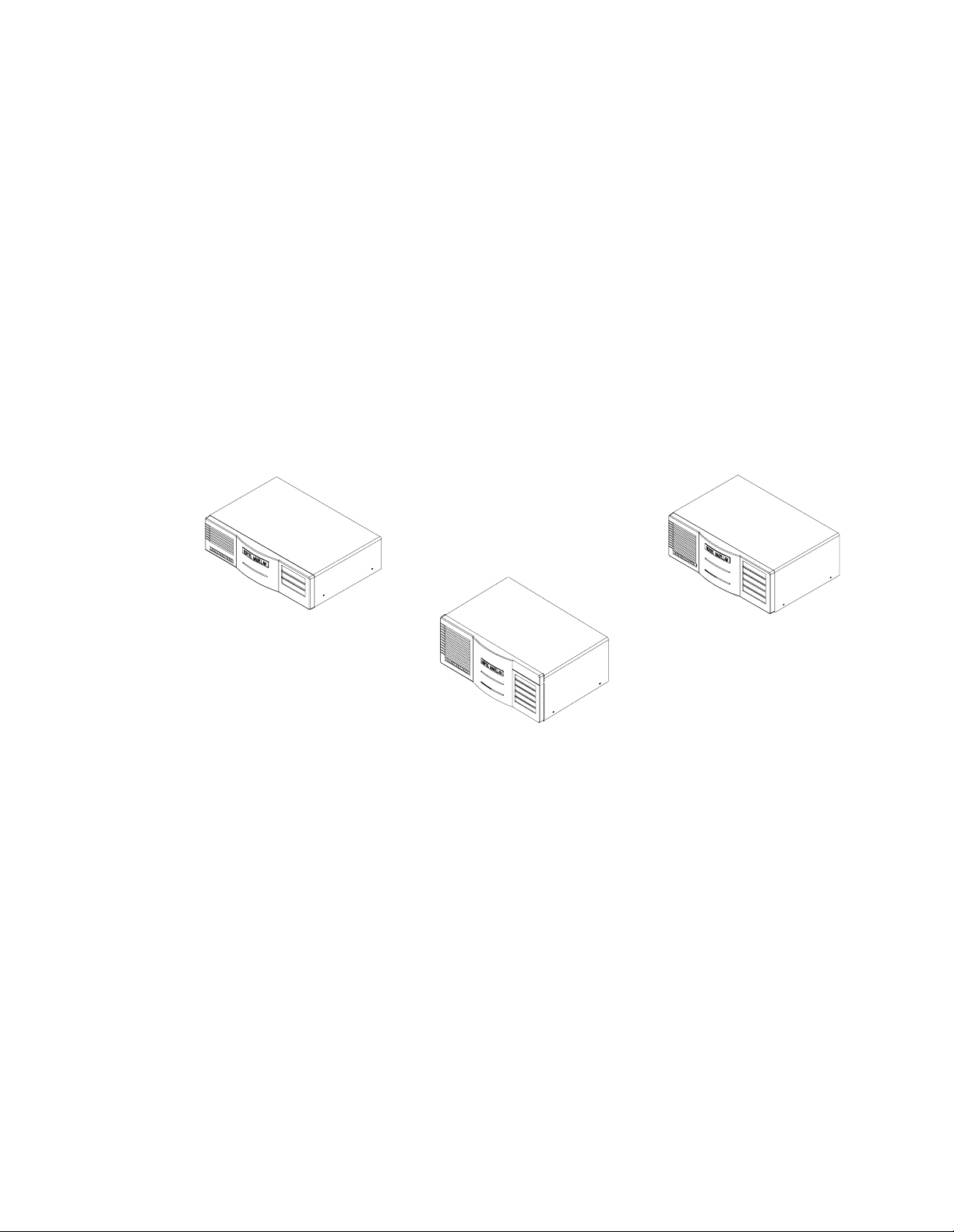
Model 4430
Models 4450
and 4455
Model 4450 and 4455 with
Redundand Power Supply
Figure 1-1. Passport 4400 Models
1-1
Page 12

IntroductionPassport 4400 Hardware Installation Manual
Passpor t 4400 units are multimedia, frame rela y access devices deployed as an
overlay to an existing P assport frame relay network. In this configuration,
Passport 4400 units form distinct networks in which separate units
communicate using switched virtual circuits (SVCs) provided by the Passport
backbone. This arrangement allows small branch sites to consolidate
multimedia traffic (such as voice and LAN) over a single low-speed network link
(operating at speeds such as 56 or 64 Kb/s) and pass tr affic through regional
concentration sites served by Passport units.
Once deployed and configured, Passport 4400 units provide the following
services:
• Voice and fax services via four different voice modules
• LAN service s such as bridging, IP Prioritization, and routing IP and
IPX protocols
• Frame Relay services
• HTDS services, for tunneling HDLC and SDLC traffic
• Constant Bit Rate (CBR) services
• Data Services (Async/TCP, SNA, X.25)
• VoIP
• OSPF
• WAN services
• Traff ic Manage ment
• Utility and Administration features
The mix of hardwar e and func tio ns in eac h Passport 4400 unit de pend s on t he
application and site requirements. The major hardware components of the
Passport 4400 unit are described in this chapter:
• 4430 AC, 3-slot unit, Ethernet Base Module, AC power - NTAU08CA
• 4450 AC, 5-slot unit, Ethernet Base Module, AC power - NTAU09CA
• 4450 DC, 5-slot unit, Ethernet Base Module, DC power - NTAU12CB
• 4450 ACR, 5-slot unit, Ethernet Base Module, AC power with
redundant power supply - NTAU10CA
• 4450 DCR, 5-slot unit, Ethernet Base Module, DC power with
redundant power supply - NT AU13CB
• 4455 AC, 5-slot unit, Ethernet Base Module, AC power with 160 watt
power supply - NTAU09NA
• 4455 ACR, 5-s lot unit , Ethernet Base Module, AC power with 200 wat t
power supply - NTAU10NA
The chassis houses the modul es that provide the various service s offered by the
Passport 4400 unit. The number of slots indicates the maximum number of
modules, including the base module, that can be supported by each unit.
1-2
Page 13

Introduction Passport 4400 Hardware Installation Manual
Ethernet Base Module
The Ethernet Base Module performs central process i ng functions for the
Passpor t 4400 u nit. This module must be pre sen t in the lowes t slot in t he unit.
The Ethernet Base Module provides support for the following:
• Processor an d memory
• Serial access port
• Management port
• 10BASE-T Ethernet interface
• Optional plug-in SIMMs
— 16 Mbyte Flash Memory SIMM
– Passport 4430/4450 - NTBQ69AA
– Passport 4455 - NTBQ70AA
— 16 Mbyte DRAM SIMM - NTAU95AA
— Data Compression SIMM - NTAU94AA
Refer to Chapter 3, Ethernet Base Module, for more detailed information
concerning this module and the optional plug-in SIMMs.
Data Modules
Data Modules are installed in the slots above the Etherne t Base Module (slots
B, C, D, E). They consist of the following modules:
The High-speed Data Module (HDM) provides additional port capability,
identical to Port 1 on the Etherne t Base Module. The module supports RS-232 /
V.24, V.35, V.36, and X.21 interfaces, determined by the cable used. The HDM
can support both DTE and DCE modes.
Legacy data m o du l es include the L egacy Data Mo d u le (LDM) and th e Le ga cy
Data Expansion Module (LEM). The LDM and LEM provide legacy protocol for
branch sites connecte d to a Passport only networ k (usually o ne which inc ludes
a Passpor t 6000 unit). These include FR, X.25, ITI, TR, SNA, SDLC, DTDS and
HTDS. The LDM provides six legacy service ports; the LEM provides an
additional eight ports.
• High-speed Data Module
— 8-Port High Speed Data Module (HDM) - NTAU74AA
— 4-Port High Speed Data Module (HDM) - NTAU83AA
• Legacy Data Modules
— 6-Port Legacy Data Module (LD M ) - NTAU73AB
— 6-Port Legacy Data Module with Token Ring (LDM) - NTAU71AB
— 8-Port Legacy Data Expansion Module (LDEM) - NTAU77AB
Refer to Chapter 4, Data Modules, for more detailed information concerning
these modul e s.
1-3
Page 14

T1/E1 and Digital Voice Modules
T1/E1 and Digital Voice Modules are installed in the slots above the Ethernet
Base Module (slots B, C, D, E). They consist of the following modules:
• T1 Voice Module
— TVM/1, Single Port - NTAY99AA
— TVM/2, Dual Port - NTAY14AA
• E1 Voice Module
— EVM/1, Single Port - NTAY15AA
— EVM/2, Dual Port - NTAY16AA
• Digital Voice Module (DVM) - NTAU60AA
— Ordering six modules - NTBQ54AA
— Ordering twelve modules - NTBQ55AA
• Digital Voice Expansion Module (DVEM) - NTAY18AA
• ISDN BRI Voice Module (IVM/2) - NTAU76BA (for use in the Passport
4430 and 4450 only)
IntroductionPassport 4400 Hardware Installation Manual
One Digital V oice Module (D VM) must be inserted in the TVM or EVM for each
digital voice channel require d. To provide f ull T1 or E1 support, the Digital V oice
Expansion Modules (DVEM) provides additional slots for DVMs as required.
Refer to Chapter 5, T1, E1, and Digital Voice Modules, for more detailed
information concerning these modules.
Analog Voice Modules
Analog V oice Modules are installed in the sl ots above the Ethernet Base Module
(slots B, C, D, E). They consist of the following modules:
• Analog Voice Module
— AVM/1, Single Channel - NTAU61AA
— AVM/2, Dual Channel - NTAU62AA
• Universal Analog Voice Module (UAVM /2) - NTAU50AA
• Voice/Fax Switch Module - NTAU52AA
Up to four analog voice modules (AVMs or UAVM s) are supported on the
Passpor t 4450 an d 4455, fo r a maximum of eight analog voic e ports. Up to two
analog voice modules are supported on the Passport 4430, for a maximum of
four analog voice ports.
1-4
The AVM and UAVM modules support the following interface modules:
• Foreign Exchange Station (FXS) - NTAY12AA
• Foreign Exchange Office (FXO) - NTLN23AA
• Ear and Mouth (E&M) - NTAY09AA
Page 15

Introduction Passport 4400 Hardware Installation Manual
Refer to Chapter 6, Analog Voice Modules, for more detailed information
concerning these modules.
Interface Modules (WAN)
Interface Modules for WAN are installed in Port2 and Port 3 on the Ethernet
Base Module.They consist of the following modules:
• WAN Serial Interface Module - NTAU03AA
• 56 kbps CSU/DSU Interface Module - NTAU02AA
• T1 CSU/DSU Interface Module - NTAU04AA
• E1 CSU/DSU Interface Module - NTAU96AA (120 ohms) and
NTA U97AA (75 ohms)
• ISDN TA U Interface Module - NTAU05AA
• ISDN TA S/T Interface Module - NTAU06AA
Refer to Chapter 7, Interface Modules (WAN), for more detailed information
concerning these modules.
1-5
Page 16

IntroductionPassport 4400 Hardware Installation Manual
1-6
Page 17

Installing the Passport 4400
This chapter describes the procedures used to set up and connect a Passport
4400 unit (Passport 4430/4450/4455).
Refer to the following manuals for relative information:
• Using Passport 4400 Install Tool Version 4.0 (800- 1983-40)
• Configuring and Operating Passport 4400 (800-2002-40) on-line
documentation
This chapter will take you through the following installation procedures:
• Prepar ing the Site on page 2- 1
• Unpacking Your Passport 4400 Unit on page 2-3
• Passport 4400 Rackmount Kit on page 2-3
• Passport 4400 Rack Installation on page 2-4
• Connecting an AC Unit on page 2-5
2
• Connecting a DC Unit on page 2-7
Preparing the Site
Before connecting the P assport 4400 u nit, select a location that conf orms to the
following environmental requirements:
•
Sp
• Surrounding temperature (page 2-3)
• Distance to the AC socket (if unit is AC-powered) – the supplied power
cord is 18.29m (6 feet) long
Note:
ace requirements (Figure 2-1, Fi gure 2-2, or Figure 2-3)
For information about installing the Passport 4400 unit in a
rack, refer to page 2-4.
2-1
Page 18
Installing the Passport 4400Passport 4400 Hardware Installation Manual
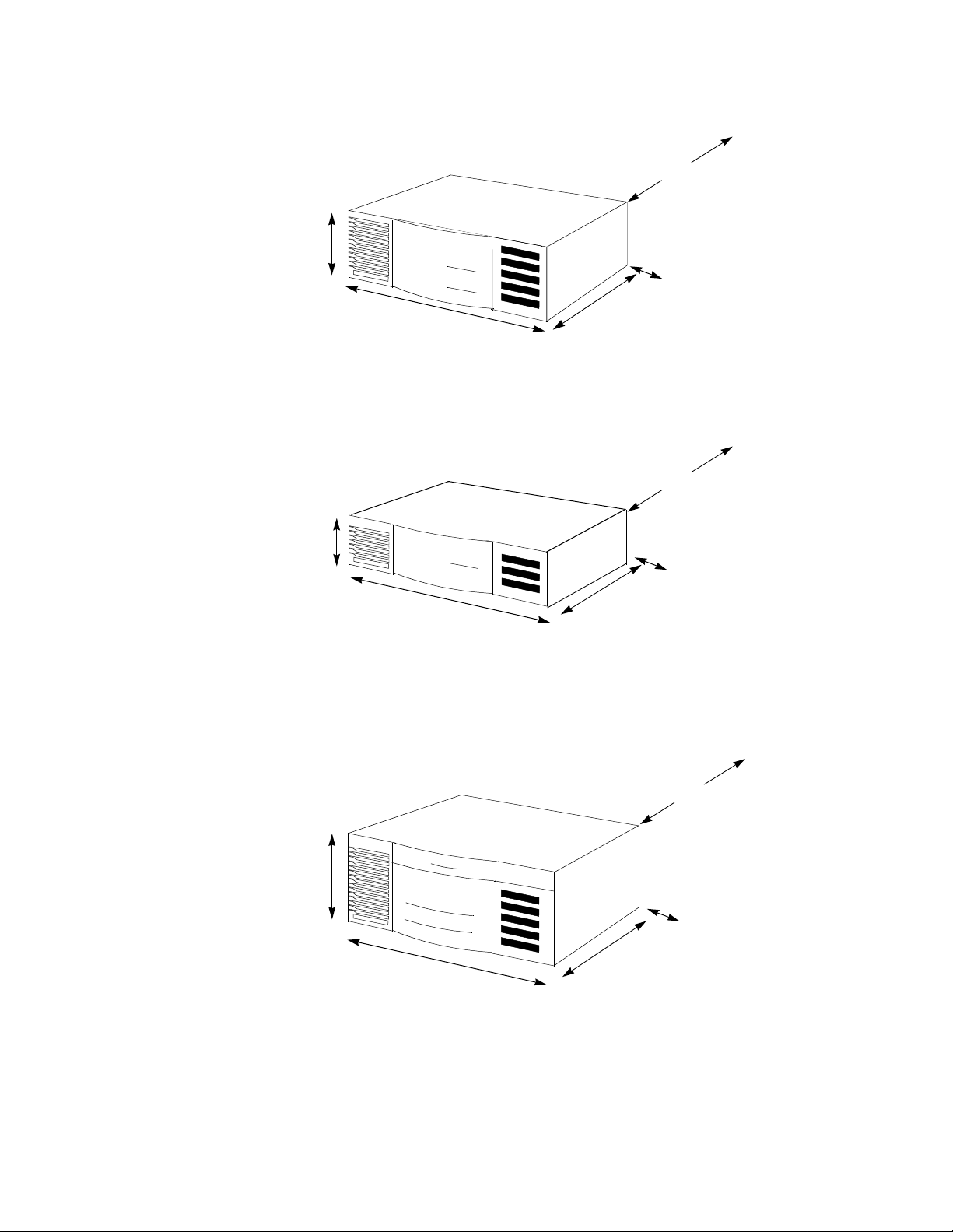
Allow 30.5 cm (12 inches), or greater, for
access to rear
16.5 cm
(6.5 inches)
44.5 cm
(17.5 inches)
*For DC models, add 5.72 cm (2.25 inches) for DC connector
Figure 2-1. Space Requirements for a Standard 5-Slot Unit
Allow 30.5 cm (12 inches), or greater, for
access to rear
12.1 cm
(4.75 inches)
44.5 cm
(17.5 inches)
*For DC models, add 5.72 cm (2.25 inches) for DC connector
Allow 5.08 cm (2 inches), or
greater, side space for air
vents
30.5 cm*
(12 inches)
Allow 5.08 cm (2 inches), or
greater, side space for air
vents
30.5 cm*
(12 inches)
Figure 2-2. Space Requirements for a 3-Slot Unit
Allow 30.5 cm (12 inches), or greater, for
access to rear
27.3 cm
10.75 inches
44.5 cm
(17.5 inches)
*For DC models, add 5.72 cm (2.25 inches) for DC connector
30.5 cm*
(12 inches)
Allow 5.08 cm (2 inches), or
greater, side space for air
vents
Figure 2-3. Space Requirements for a 5-Slot Redundant Power Supply Unit
2-2
Page 19

Installing the Passport 4400 Passport 4400 Hardware Installation Manual
Environmental Specifications
Temperature - Operating: 0 to 50°C (32° to 122°F)
Storage: -40
Relative Humidity - Operating: 10% to 90% (non-condensing)
Storage: 0% to 95% (non-condensing)
to 70°C (-40° to 158°F)
°
Unpacking Your Passport 4400 Unit
Follow the instructions below to unpack your Passport 4400 unit.
1. Read the labels on the box prior to opening the box.
Note:
2. Remove the shipping material and any hardware (cables , modules , etc.)
shipped in the box along with the Passport 4400 unit. Place these
modules on a table near the installation site.
3. Slowly ease the Passport 4400 unit out of the carton by f irmly gripping
its sides and lifting straight up . (Be sure to use proper lifting te chnique
when removing the Passport 4400 unit from the car ton. Do not bend
over at the back when lifting.)
4. Place the equipment out on a table close to the ins tallation site.
5. Check the packing list agains t the cont ents. Report any damage or lost
articles to the shipping carr ier.
6. Save the packing materials in case you need to move the unit.
Once the carton is unpacked, verify that you have received all the equipment
you have ordered.
Make sure that you keep the packing list included. It contains
model numbers and information about the Passport 4400 unit
and all modules included.
Passport 4400 Rackmount Kit
The Passp ort 4400 u nit ma y be install ed in a rac k using an a vailable Passport
4400 rackmount kit.
In addition to the rackmount shelf, each kit contains the following parts:
• Four screws
• Four washers — nylon filler
• Four washers — nickel finish
• Four clip nuts
2-3
Page 20
Passport 4400 Rack Installation
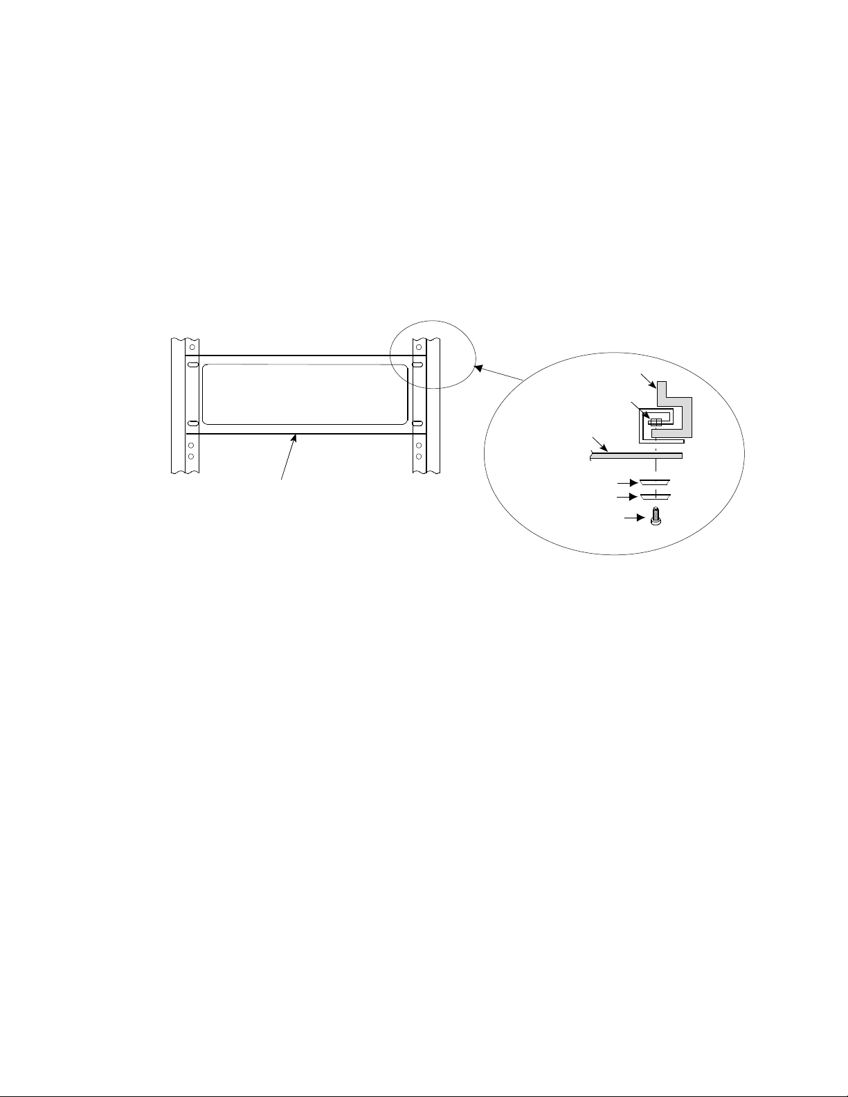
1. Install the clip nuts on the rack.
2. Place the shelf in the rack.
3. Secure both sides of the shelf to the rack, using the provided scr ews and
washers (see Figure 2-4 below).
4. Position the unit on the rackmount shelf from the rear. Place the front
of the unit through the cutout in the front of the rac kmount shelf (see
Figure 2-5 on page 2-5).
Installing the Passport 4400Passport 4400 Hardware Installation Manual
T op Vie w
Rack
Clip nut
Shelf
Shelf
Washer - Nylon filler
Washer - Nickel finish
Screw
Figure 2-4. Installing the Shelf
2-4
Page 21
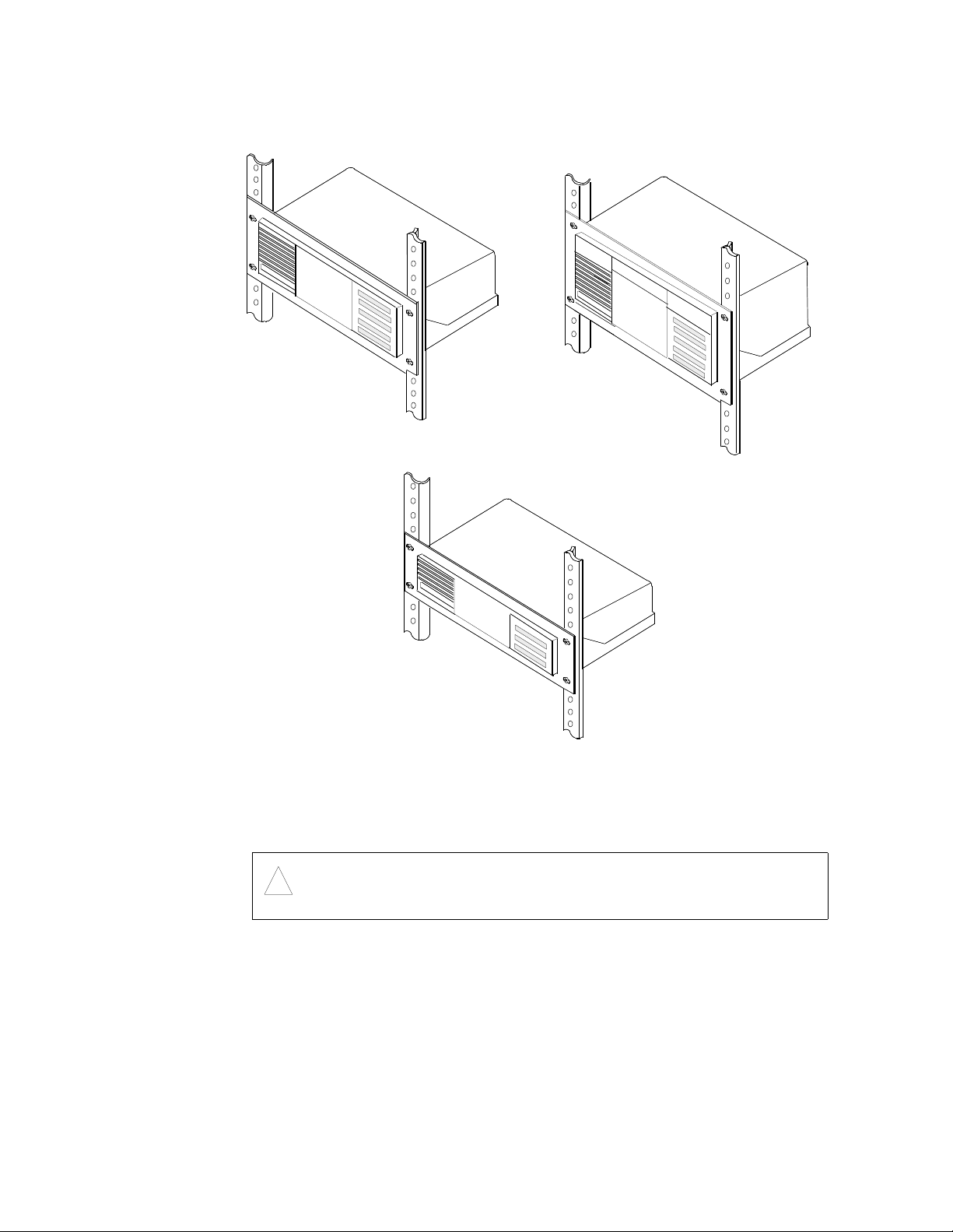
Installing the Passport 4400 Passport 4400 Hardware Installation Manual
Rack-mounted
5-Slot Chassis Unit
Passport 4450
Rack-mounted Unit with
Redundant Power Supply
Passport 4455
Figure 2-5. Passport 4400 Unit in Rackmount Shelf
Connecting an AC Unit
Warning:
!
All AC-powered Pas sport 4400 models require an agency-recognized AC power
cord, rated at 125 V and 10 Amps . If a power cord is not sup plied with your AC
unit, make sure that any power cord used with the Passport 4400 unit meet
these specifications. Passpor t 4400-approved AC power cords may be ordered
separately.
Rack-mounted
3-Slot Chassis Unit
Passport 4430
Before the unit is turned on, make sure there is a separate ground
wire connection between the unit chassis and input power source
ground.
2-5
Page 22
Installing the Passport 4400Passport 4400 Hardware Installation Manual
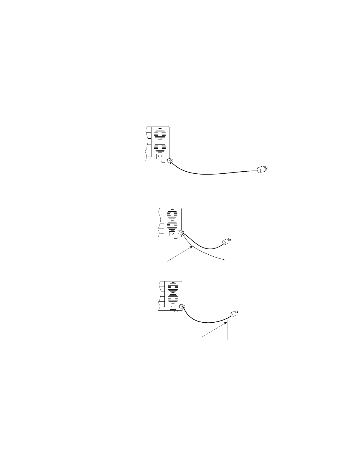
If an AC power cord is s upplied with your unit, t he power cord should be one of
the following
• A molded three-prong power cord with an appropriate connector to
match the power outlet in your country, as shown in Figure 2-6 below.
• A power c ord with a two-prong power connector and a green-with-yellow
stripe ground wire as shown in the examples in Figure 2-7 below. If the
power outlet is not grounded, contact an electrician to connect the
green-with-yellow stripe wire to a fixed earth grounding point.
Figure 2-6. Power cord — Grounded
Green with Yellow Stripe
Ground Wire
Three-wire power cord
Two-wire
Power Cord
0.5 ohm
<
Three-wire
Power Cord
To a Fixed Earth
Ground Point
Typic al
connector
Two Prong Power Connector
Two prong power connector
<
0.5 ohm
2-6
Green with Yellow Stripe
Ground Wire
To a Fixed Earth
Ground Point
Figure 2-7. Power cord — Ungrounded
T o power the unit on, plug the power cord supplie d with your unit into the back
of the chassis and into an appropriately ground ed three-pin wall outlet.
Page 23
Installing the Passport 4400 Passport 4400 Hardware Installation Manual
Connecting a DC Unit
Before applying power to the Passport 4400 unit, make sure that
Warning:
!
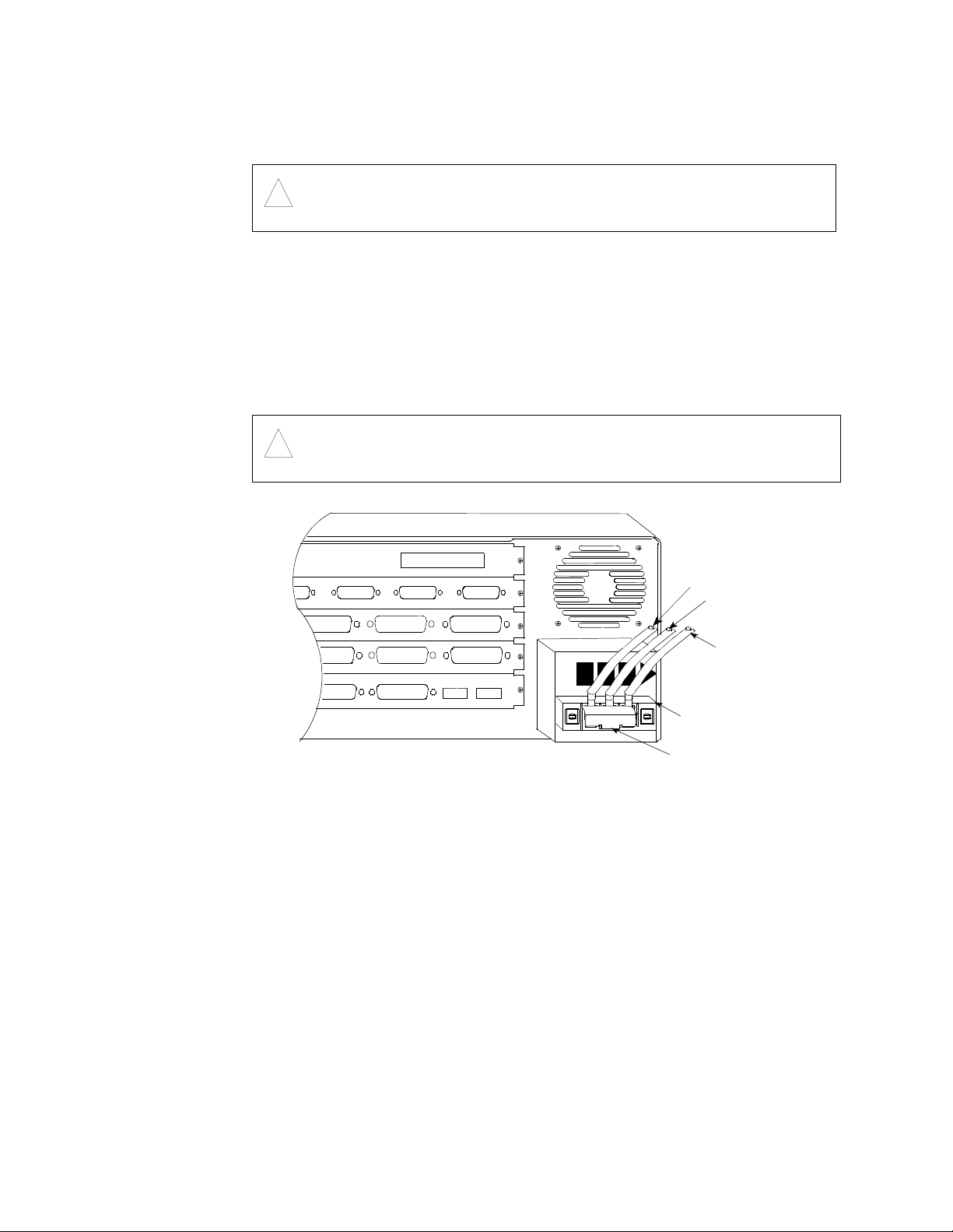
The DC version of the P assport 4400 unit has an external terminal block located
on the back of the unit below the fan vents. A small black plas tic door covers
the terminal points . To access the terminal points, gently pull off the plastic
door from the top with your finger.
The DC power source must be connect ed to the unit by attaching t he +48 VDC ,
-48 VDC, and the chassis ground cords to their respective terminal points located
on the block as shown below.
Warning:
!
the unit is properly grounded.
The connector attaching the Passport 4400 unit to the DC power
source must have a single disconnect switch.
E
D
C
B
A
Chassis
Return
-48
+48
Chassis ground
+48 VDC (return)
-48 VDC
Terminal block
Plastic door
Figure 2-8. Location of DC Connection in Terminal Block
After the P assport 4400 unit is proper ly connected, you will have to verif y that
it is operating properly.
Refer to Chapter 8, Indicators, for infor mat ion on the indicator functions .
Refer to Chapter 11, Connecting a W orkstation, for information con cerning the
port connections on the Passport 4400 unit.
2-7
Page 24

Installing the Passport 4400Passport 4400 Hardware Installation Manual
2-8
Page 25
Ethernet Base Module
3
The Ethernet Base Module (EBM) performs central processing functions for any
Passport 4400 unit (4430/4450/4455).
This chapter contains information on the following features:
• Attaching Cables to th e Et h e rn et Base Modul e on pa g e 3-3
• Management Port on page 3-4
• Frame Relay DCE Serial Access P ort (Port 1) on page 3-4
• Ethernet Access Port on page 3-6 (10BASE-T)
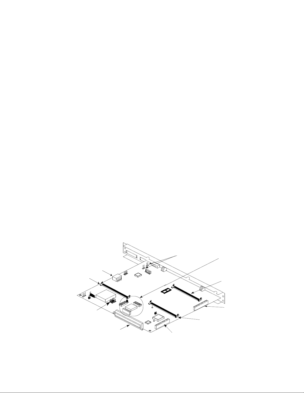
The Ethernet Base Module includes the following:
• Processor an d memory
• Serial access port
• Management port
• Ethernet interfaces (10BASE-T)
• Optional SIMMs.
Power Connector
16MB DRAM SIMM
(J6 Connector)
E21 and E23 Jumpers
– 16 Mbyte Flash Memory SIMM
– 16 Mbyte DRAM SIMM
– Data Co mpression SIMM
Fan Connectors
Indicators
Stacking Connector
for all Modules
Stacking Connector
for HDM Modules
Data Compression
SIMM - (J13 Connector)
Stacking Connector
for all Modules
16MB Flash SIMM
(J9 Connector)
Figure 3-1. Internal Components of the Ethernet Base Module
3-1
Page 26
Ethernet Base ModulePassport 4400 Hardware Installation Manual
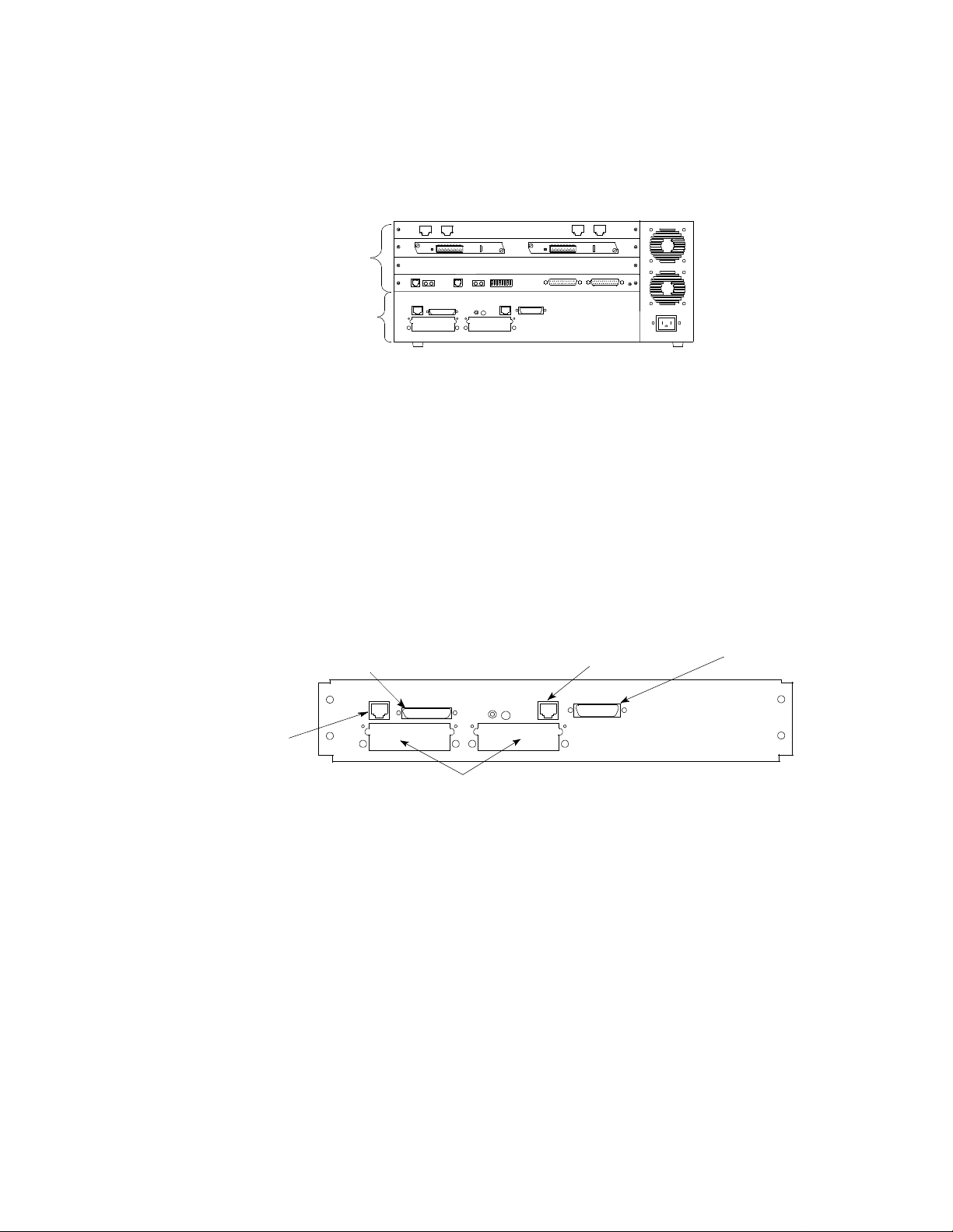
The Ethernet Base Module must be present in the lowest slot (A) for the unit
to function. The remaining slots (B, C, D, E) house optional expansion voice or
data modules as required. The figure below shows the rear view of a typical
Passport 4450 unit.
E
Optional Modules
D
C
B
Ethernet Base Module
Port 2
Port 3
Figure 3-2. Passport 4450 Unit - Rear View
The Ethernet Base Module has six ports located on the back panel. The AUI
port is not used at this time. The five usable ports are as follows:
• Management port
• Frame Relay DCE/DTE, Port 1
• Ethernet Access Port (10BASE-T)
• Port 2 (WAN)
• Port 3 (WAN)
Frame Rela y DCE Serial
Access Port (Port 1)
Management Port
Ethernet Access Port
10BASE-T
Not Used
(AUI)
3-2
Interface Modules
(Port 2 and Port 3)
Figure 3-3. Ethernet Base Module (All Models) - Rear View
Note:
Should you need to remove the Ethernet Base Module, refer
to Chapter 10, General Installation, for information on
opening the unit and removing the modules.
Page 27

Ethernet Base Module Passport 4400 Hardware Installation Manual
Port 2 and Port 3 are slots for optional plug-in Interface Modules supporting
the following options:
• 56 Kb/s CSU/ DSU
• T1 CSU/DSU
• E1 CSU/DSU
• ISDN U and S/T Interf aces
• Serial WAN
For more information on the interface modules, refer to Chapter 7, Interface
Modules (WAN).
Attaching Cables to the Ethernet Base Module
The connections made in this procedure will depend on the spec ific site
requirements. If you are not sure of the exact connections required for the
Passport 4400 unit, consult your system administrator.
The following connections are only used if required.
• Connect the Management Port using an RJ-45 cable (page 3-4)
• Connect the Frame Relay DCE port using a DB-50 cable (page 3-5)
• Connect the Ethernet Access Port by using the RJ-45 cable to the
10BASE-T port (page 3-6)
Refer to the following chapter s for added information:
• Chapter Figure 11, Connecting a Workstation
• Appendix A, Cable Diagrams
• Appendix B, Agency and Telephone Company Requirements.
• Appendix D, T1 Voice Module Cabling Requirements.
3-3
Page 28
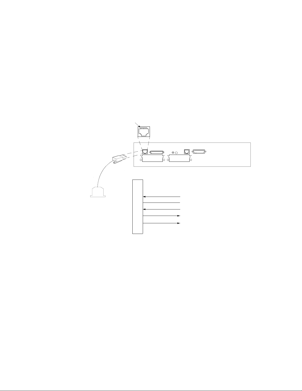
Management Port
The Management Port, located on the back panel of the Ethernet Base Module,
allows you to connect the Passport 4400 unit to a Command Port (PC/CPU) or
to a modem.
The Management Port has the following functions:
• Supports asynchronous operation using an RS-232/V.24 physical driver
• Data rate is automatically selected for speeds from 9.6 to 38.4 Kb/s
Ethernet Base ModulePassport 4400 Hardware Installation Manual
• Management port is RS-23 2/V .24
a crossover cable is required for DTE
−
operation
Pin 1
RJ-45
RJ-45 Pin Assignments
1
2
DB-25
3
4
5
6
7
8
Pins 1, 2 and 8 Not Connected
Figure 3-4. Management Port Connectors and Pin Assignments
Data Transmit Ready (DTR)
Signal Ground (SG)
Receive Data (RxD)
Transmit Data (TxD)
Clear to Send (CTS)
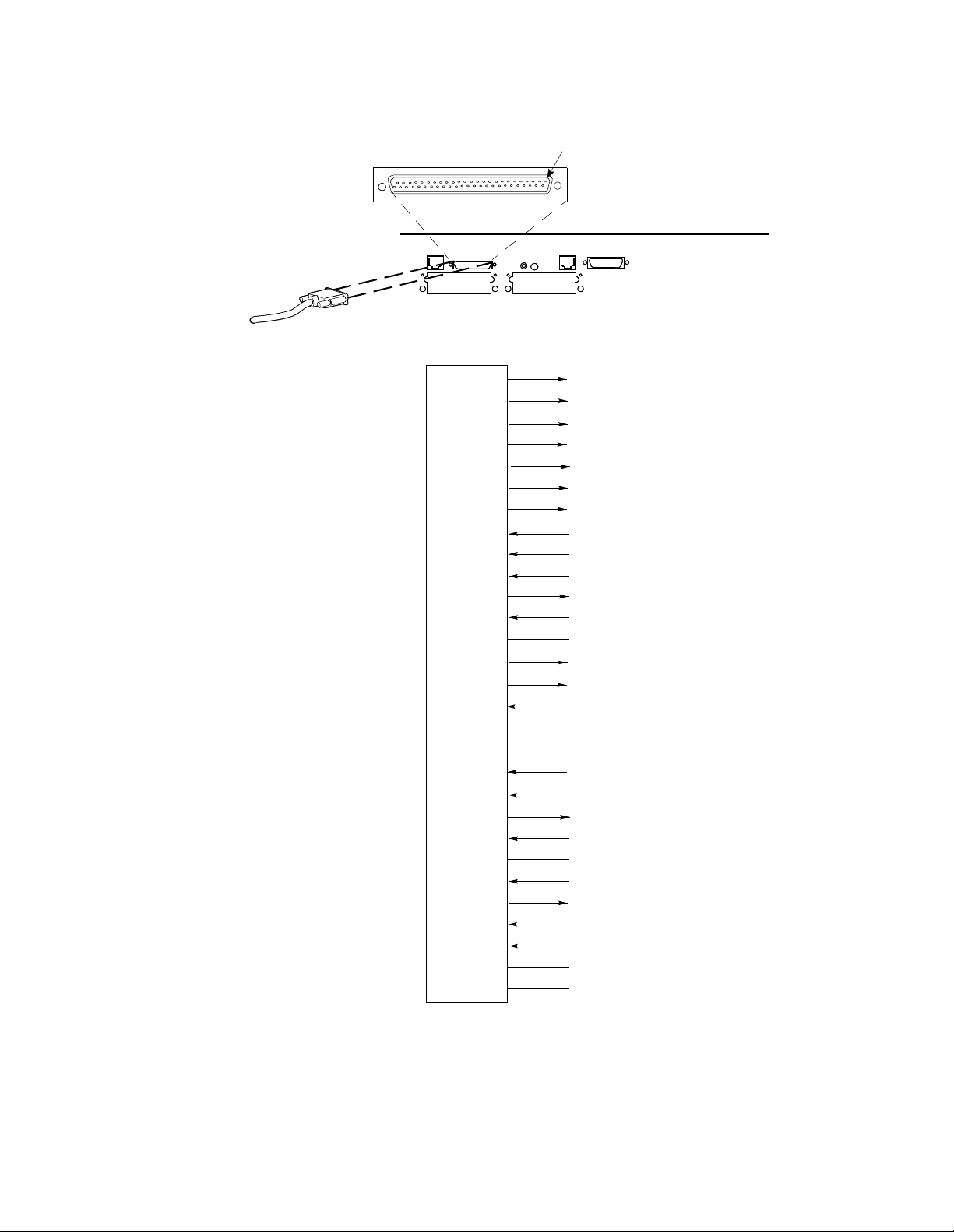
Frame Relay DCE Serial Access Port (Port 1)
The Frame Relay DCE Serial Access Port (Port 1), located on t he back panel o f
the Ethernet Base Module, has the following fe atures:
• 50-pin serial data port
• Interface determined by cable: RS-232/V.24, V.35, V.36, or X.21
• Mode (DCE or DTE) determined by cable.
Notes: •
3-4
In DCE mode, the management port supplies the DTE
with both transmit and receive clock.
•
In DTE mode, clocking is provided externally for both
transmit and receive. Default clocking speed in 192 Kb/s.
Page 29
Ethernet Base Module Passport 4400 Hardware Installation Manual
Pin 1
50-Pin Connector
1, 2
3, 28
4, 29
5, 30
6, 31
7, 32
8, 33
9, 34
10, 35
11, 36
16
18
19, 38, 44
20, 45
21, 46
22, 47
23, 24, 25
26, 27, 39
43, 48, 49
12
13
14
15
17
37
40
41
42
50
Interface Type Indication
V.35 Transmit Data
V.35 External Receive Data Clock
V.35 External Transmit Data Clock
V.36/X.21 Transmit Data
V.36/X.21 External Receive Clock
V.36 External Transmit Clock/X.21
RS-232/V.24/V.35/V. 36 Cle ar to Send/ X.21
RS-232/V.24/V.35/V.36 Data Set Ready
RS-232/V.24/V.35/V.36 Carrier Detect
RS-232/V.24/V.35/V.36 Ready to Sen d
Unassigned
Cable Present Status
RS-232/V.24 Externa l Rece ive Data Clo ck
RS-232/V.24 Transmit Data
RS-232/V.24 Transmit Data Clock
DTE Signal Return
Reserved
V.35/V.36/X.21 Receive Data
V.35/V.36/X.21 Transmit Data Clock
V.35/V.36 Receive Data Clock/X.21 Indication
V.35 Input Termination Ground
Logic Ground
RS-232/V.24/V.35/V.36 Data Terminal Ready
RS-232/V.24 External Transmit Data Clock
RS-232/V.24 Receive Data
RS-232/V.24 Receive Data Clock
Logic Ground
Logic Ground
Figure 3-5. Pin Assignments Frame Relay DCE Serial Access Port (Port 1)
and All Data Modules
3-5
Page 30
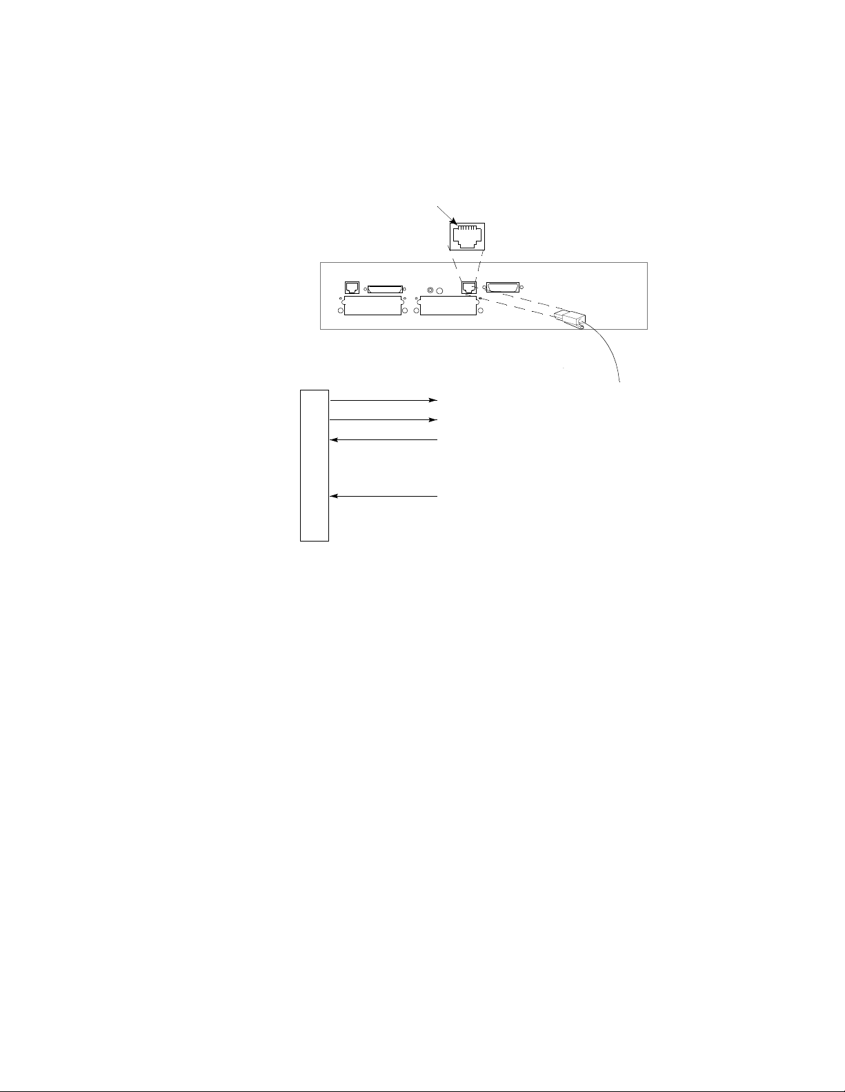
Ethernet Access Port
The Ethernet Access P ort (10BASE-T), loc ated on the back panel of the Ethe rnet
Base Module, connects the Passport 4400 to the Ethernet.
Ethernet Base ModulePassport 4400 Hardware Installation Manual
Pin 1
RJ-45
RJ-45 Pin Ass ignments
1
2
3
4
5
6
7
8
Pins 4, 5, 7, 8 Not Connected
(Tx+) Transmit Data Positive
(Tx-) Transmit Data Negative
(Rx+) Receive Data Positive
(Rx-) Receive Data Negative
To Ether net
Figure 3-6. Ethernet 10BASE-T Connector and Pin Assignments
Refer to the following chapter s for added information:
• Appendix B, Agency and Telephone Company Requirements.
• Appendix D, T1 Voice Module Cabling Requirements.
3-6
Page 31

Ethernet Base Module Passport 4400 Hardware Installation Manual
16 Mbyte Flash Memory
A 16 Mbyte Flash Memory SIMM (Passport 4430/4450 - NTBQ69AA, P assport
4455 - NTBQ70AA) must be installed for Release 2.0 and above soft w are. This
daughterboard contains the latest s oftware configuration f or the Passport 4400
unit and can be either factory installed or field upgradable . This SIMM is plugand-play and no jumper settings need to be altered.
Figure 3-7. 16 Mbyte Flash Memory SIMM
F or inst ructions on removing and inst alling the SIMM, re fer to Removing and
Installing SIMMs on page 3-10.
Front
Figure 3-8. Location of 16 Mbyte Flash Memory SIMM Connector
16MB Flash SIMM
(J9 Connector)
3-7
Page 32

16 Mbyte DRAM
The Passport 4400 offers an optional 16 Mbyte DRAM SIMM (NTAU95AA)
offers an optional is needed for softw are version 3.1 and above. F or instructions
on removing and installing the SIMM, refer to Removi ng and Installing SIMMs
on page 3-10.
The correct E21 and E23 jumper block positi ons for the 16 Mbyte DRAM SIMM
is 4M, (as opposed to 1M for the 8 Mbyte DRAM SIMM) as shown in Figure 3-10.
Ethernet Base ModulePassport 4400 Hardware Installation Manual
Figure 3-9. 16 Mbyte DRAM SIMM
Note:
When installing the 16 Mbyte DRAM SIMM, you must have
the E21 and E23 jumpers (2 each) set in the correct position
(4M) for your unit to boot up after installation.
Use a pair of small needle-nose pliers when making changes to the jumper
settings. Carefully li ft each jumper block and p lace it over the appropriate pi ns.
See Figure 3-10 for location of E21 and E23 jumpers.
Jumper Blocks (4)
E21 (2)
E23 (2)
16MB DRAM SIMM
(J6 Connector)
E21 and E23 Jumpers
Front
Jumper Settings for
16 Mbyte DRAM SIMM
E21
Front of Unit
E23
4M
Top View of E21 and E23 Jumper
1M
Front of Unit
Top View of E21 and E23 Jumper
Jumper Settings for
8 Mbyte DRAM SIMM
1M
E21
E23
4M
3-8
Figure 3-10. Location of 16 Mbyte DRAM SIMM Connector and Jumper Settings
Page 33

Ethernet Base Module Passport 4400 Hardware Installation Manual
Data Compression
The Data Compression feature (NT AU94AA for Release 4.0 and later) enhances
the speed of the data supporting RFC1490 SVC and preconfigured RFC1490
PVCs. This SIMM is plug-and-play and no jumper settings need to be altered.
Figure 3-11. Data Compression SIMM
Note:
Be sure you have the correct Ethernet Base Module
(NTAU01BA or later version) before installing and using this
feature.
Refer to Figure 3-12 for location of the Data Compression SIMM connector (J13).
F or instructions on re moving and installing the modul e, ref er to Removing and
Installing SIMMs on page 3-10.
Data Compression
SIMM - (J13 Connector)
Front
Figure 3-12. Location of Data Compression SIMM Connector
3-9
Page 34

Removing and Installing SIMMs
Instructions for removing and installation are the same for the following
SIMMs:
• 16 Mbyte Flash Memory SIMM
• 16 Mbyte DRAM SIMM
• Data Compression SIMM
Follow the procedure below to remove a SIMM in the P assport unit:
1. Gently push out t he connector locking f langes located at each sid e of the
slot housing the SIMM.
2. Move the SIMM to a vertical position.
3. Lift up the SIMM.
Ethernet Base ModulePassport 4400 Hardware Installation Manual
1.
2.
3.
Follow the procedure below to install or replace a SIMM in the Passport unit.
Do not attempt to remove or install any SIMM while power is
Warning:
!
connected to the Passport unit. Be sure to disconnect the unit
from the power source.
1. Insert the SIMM into the connector.
2. Gently push down and the back on the SIMM.
3. The SIMM will “click” into the connector locking flanges.
1.
2. 3.
“CLICK”
“CLICK”
3-10
Page 35

This chapter describes the types of Data Modules available for your Passport
4400 unit (4430/4450/4455). These modules are defined as Legacy Data Modules
and High-Speed Data Modules.
Legacy Data Modules are described as follows:
• 6-Port Legacy Data Module
• 6-Port Legacy Data Module (with Token Ring)
• 8-Port Legacy Data Expansion Module
• LDM Memory Expansion Module
High-Speed Data Modules are described as follows:
• 8-Port High -Speed Data Mod u le
• 4-Port High -Speed Data Mod u le
Legacy Data Modules
Data Modules
4
Low-speed data service is provided vi a the Legacy Data Module (LDM) and the
Legacy Data Expansion Module (LEM).
4-1
Page 36

Legacy Data Module (6-Port and 6-Port with Tokin Ring)
This module provides interface ports that support legacy data protocol in
Passpor t 4400 u nits. Available modules are as follows:
• 6-Port - (NTAU73AB)
• 6-Port with Tokin Ring (NTA U71AB)
Data ModulesPassport 4400 Hardware Installation Manual
Rear View
Data Ports
50-pin Connectors
(see Figure 3-5 on
page 3-5 for pin
assignments)
Indicators
Pin 1
Management Port
RJ-45 Interface
RJ-45
1
Pins 1, 2, 8 Not Connected
2
3
4
5
6
7
8
Data Terminal Ready
Signal Ground
Receive Data
Transmit Data
Clear to Send
Pin 1
DB-9 Connector for Token
Ring Serial Interface
1
2
3
4
5
6
7
8
9
Pins 2, 3, 4, 7, 8 Not Connected
Module Switch Group
(see Figure 10-1 on
Rx+
TxRx-
Tx+
page 10-3)
4-2
Stacking
Connectors
Back
Figure 4-1. Legacy Data Module
Page 37

Data Modules Passport 4400 Hardware Installation Manual
Legacy Data Expansion Module
The Legacy Data Expansion Module (NTAU77AB) offers additional interface
ports that support Legacy Data protocol in your Passport 4400 unit.
Note:
The connections will depend on the specific site requirements. If
you are not sure of the exact connections required for the
Passport 4400 unit, consult your system admin is trator.
Use a 50-pin connector to join eac h serial data port to your local equip ment. The
type of cable used will depend on the class of service you desire. Refer to
Appendix A, Cable Diagrams, of this manual.
Rear View
Data Ports
50-pin Connectors
(see Figure 3-5 on
page 3-5 for pin
assignments)
Stacking Connectors
Indicators
Back
Figure 4-2. Legacy Data Expansion Module
Module Switch Group
(see Figure 10-1 on
page 10-4)
Memory Expansion Module for Legacy Data Module
For Passpor t 4400 units containing a Legacy Data Module and one or more
Legacy Data Expansion Modules, you must ord er an LDM Memory Expansion
Module for the Legacy Data Module. This module provides 1 Mbyte of SRAM
memory required to support the additional ports provi ded by the Legacy Data
Expansion Module.
Installation Procedure for the Memory Expansion Module
The following procedure explains how to install a Memory Expansion Module
on the Legacy Data Module already installed in the Passport 4400 unit.
F or informati on on o pening the un it and removing/ins talli ng modules, refer to
Chapter 10, General Installation.
Modules cannot be inserted into or removed from the unit while
the Passport 4400 unit is operating. This could cause damage to
the unit or interruption of network service or both.
!
Caution:
4-3
Page 38

Data ModulesPassport 4400 Hardware Installation Manual
Caution:
!
Warning:
!
Do not connect external cables until module installation is
complete.
When working inside the unit, be sure to take all precautions
against electrostatic discharge.
1. Disconnect the power from the chassis.
2. Remove the cover.
3. Remove all cables from the Legacy Data Module that the Memory
Expansion Module will be installed on.
4. Remove all modules above the Legacy Data Module.
5. Remove the Legacy Data Module.
Note:
When installing the Memory Expansion Module on to the Legacy
Data Module, firmly support the bottom side of the area where
the Memory Expansion Module is being installed to limit the
flexing of the Legacy Data Module.
6. Line up the connectors on both modules; the latching posts on the Legacy
Data Module must line up with the mounting holes located on the Memory
Expansion Module.
7. Ensure that the connectors are fully seated and the latching posts are
properly latched (see Figure 4-3).
8. Install a two-position shorting jumper (provid ed) onto the heade r marked
BD P18 (see Figure 4-3).
9. Install the Legacy Data Module and the modules that were removed in
step 4.
10. Install all cables, rep lace the co ver, and reconnect the power t o the c hassis.
4-4
Page 39

Data Modules Passport 4400 Hardware Installation Manual
Legacy Data Module
Install Jumper on Position Marked P18 BD
Figure 4-3. Legacy Data Module with Memory Expansion Module Installed
High-Speed Data Modules
Memory Expansion
Module
Latching
Posts
Module Switch Group
(see Figure 10-1 on
page 10-3)
P16
IS
P17
WD
P18
BD
P19
KD
J11
There are two models of High-Speed Data Modules (HDMs):
• 8-Port High Spe e d Da ta Module (NTAU74AA)
• 4-Port High Spe e d Da ta Module (NTAU83AA)
The High-Speed Data Module provides additional port capability, identical to
port 1, on the Ethernet Base Module. The module supports RS-232 /V.24, V.35,
V .36, and X. 21 interfaces, determined by the cable used. The module c an support
both DTE and DCE mode.
Note:
Connections depend on the specific site requirements. If you
are not sure of the exact connections required
See Figure 3-5, on page 3-5, for Data Port pin assignments.
The Ethernet Base Module has three stacking connectors (see Figure 3-1 on
page 3-1) for the High-Speed Data Module that mount int o the three connectors
(see Figure 4-4 below) located on the High-Speed Data Module. These connectors
on the High-Speed Data Module are on both the top and underside of the module.
Make sure these connectors are properly fitted.
4-5
Page 40

Attaching Cables to the High-Speed Data Module
Cable connections made in this procedure will depend on the specific site
requirements. If you are not sure of the connections required for the Passport
4400 unit, consult your system administrator.
For more information about cables, refer to Appendix A, Cable Diagrams.
Data ModulesPassport 4400 Hardware Installation Manual
Rear View
Indicators
4 Port
8 Port
Stacking Connectors
for High-Speed Data
Module
Figure 4-4. High-Speed Data Module
Data Ports
50-pin Connectors
(see Figure 3-5 on
page 3-5 for pin
assignments)
Module Switch Group
(see Figure 10-1 on
page 10-3)
Back
For further information about cables, refer to Appendix A, Cable Diagrams.
4-6
Page 41

T1, E1, and Digital Voice Modules
This chapter describes the hardware features and physical descriptions of the
voice modules (digital) that provide the Passport 4400 unit (4430/4450/4455)
with T1 or E1 connectivity and digital/analog voice options. Included are the
following modules:
• T1 Voice Module on page 5-2
— The Single Port T1 Voice Module (TVM/1 - NTAU99AA) provides
connection to a single T1 line DS-1).
— The Dual Port T1 Voice Module (TVM/2 - NTAY14AA) provides
connections to two T1 lines (DSX-1 and DS-1).
• E1 Voice Module on page 5-4
— The Single Port E1 Voice Module (EVM/1 - NTAY15AA) provides
connections to a single E1 line (L1).
— The Dual Port E1 Voice Module (EVM/2 - NTAY16AA) provides
connections to two E1 lines (L1 and L2).
5
• Digital Voice Expansion Module on page 5-10 (NTAY18AA), is an
expansion module that contains slots to support ad ditional Digital V oice
Modules. To support a full T1 or E1 link, two Digital Voice Expansion
Modules in addition to the T1 Voice Module or E1 Voice Module are
required.
• DVEM Power Harness on page 5-11 (NTAU32AA), provides additional
power to the Digital Voice Expansion Module.
• Digital Voice Module on page 5-12 (NTAU60AA), is a SIMM card
(daughterboard) that is installed d irectly onto the T1 Voice Module, the
E1 Voice Module, or the Digital Voice Expansion Module. Each Digital
Voice Module supports one digit al vo ice channel.
• Removing and Installing Daughterboards is discussed on page 5-13
• ISDN BRI Voice Module on page 5-14 ( IVM-BRI/ST/2- NTAU76CA), is
an expansion module providing the P assport 4400 unit with an ISDN
interface for connection to an ISDN PBX, ISDN phone, or other ISDN
protocol.
Refer to the following chapter s for added information:
• Chapter 8, Indicators
• Chapter 11, Connecting a Workstation
• Appendix A, Cable Diagrams
• Appendix B, Agency and Telephone Company Requirements.
• Appendix D, T1 Voice Module Cabling Requirements.
5-1
Page 42

T1 Voice Module
The T1 Voice Module is available in a single (TVM/1E - NTAY99AA) or dual
(TVM/2 - NTAY14AA) model. These modules provide an interface t o one or t wo
1.544 Mbytes T1 lines (DS-1 for connection to T1 network services and DSX-1
to a local PBX).
The T1 V oice Module also provides additional T1 connectivit y for two high-speed
data ports, DP1 and DP2, and to the primary and secondary ports of the Ethernet
Base Module of the Passport 4400 unit.
The T1 Voice Module c an support a maximum of 24 Digital Voice Modules (6 on
the T1 Voice Module; 18 on Digital Voice Expansion Modules).
Receptacles (6) for
Digital Voice Modules
Front
T1, E1, and Digital Voice ModulesP assport 4400 Hardware Installation Manual
Module
Switch Group
LED Block
Stacking Connectors
DP2
DP1
Rear
(Back Panel)
Figure 5-1. T1 Voice Module
5-2
Page 43

T1, E1, and Digital Voice Modules Passport 4400 Hardware Installation Manual
Connectors and Pin Assignments
The figure below shows the connectors and pin assignments located on the backpanel of the T1 Voice Module. All pin assignments and other features are the
same for single and dual port modules .
DSX-1
(dual-port only)
DS-1
Data Ports
See Figure 5-7, Figure 5-8,
and Figure 5-9
Pin 1
Pin 1
RJ-48
RJ-48
T ransmit Pair
to T1
(Monitor
1
2
3
4
5
6
7
8
Ring (R)
Tip (T)
Ring 1 (R1)
Tip 1 (T1)
Only)
Transmit Pair
from T1
(Monitor Only)
-7.5 dB
LBO
-15 dB
LBO
12345678
0 dB
LBO
12345678
12345678
Figure 5-2. Pin Assignments for T1 Voice Module - Single and Dual Port
Note:
The connections will depend on the specific site
requirements. If you are not sure of the connections required
for the Passport 4400 unit, consult your system administrator
or refer to the following:
• Chapter 11, Connecting a Workstation.
• Appendix A, Cable Diagrams.
• Appendix B, Agency and Telephone Company Requirements.
UP
DOWN
• Appendix D, T1 Voice Module Cabling Requirements.
5-3
Page 44

E1 Voice Module
The E1 Voice Module is available in a single (EVM/1) or dual (EVM/2) port
module. The E1 Voice Module provides a user interface to one or two 2.048
Mbytes E1 lines, L1 inte rface, to a local PBX and a L2 i nterfac e for conne ctio n
to E1 network se r vi ce s ) .
The E1 Voice Module houses up to six Digital Voice Modules (DVMs). It can
support a maximum of 30 Digital Voice Modules (6 on the E1 Voice Module
module, 12 on each Digital Voice Expansion Modules). The Passport 4450/4455
can house a maximum of three Digital Voice Expansion Modules, while the
Passport 4430 can house two Digital Voice Expansion Modules.
T1, E1, and Digital Voice ModulesP assport 4400 Hardware Installation Manual
Module Switch Group
(see Figure 10-1
on page 10-3)
Digital Voice Modules
DVEM
Expansion Connector
LED Block
Feed-through Stacking
Connector
Receptacles for
Figure 5-3. E1 Voice Module (Dual Port)
The E1 module can be connected with either a 75 ohm or a 120 ohm termination.
These terminations are determined by jumper settings on the module boar d. If
you are unsure how these jumpers are set or if you w ant to change the settings
on the unit you have received, refer to Fi gure 5-6 on page 5-6, before connecting
this module.
5-4
Note:
The pin assignments and other features are the same for
single and dual port modules.
Page 45

T1, E1, and Digital Voice Modules Passport 4400 Hardware Installation Manual
Receive
Pair
For 75 ohms
Interface
L1
Transmit
Pair
(dual-port only)
Pin 1
Same as Line 1
DB-9 Connector
For 120 ohms
Balanced pair
Interface
1
2
3
4
5
6
7
8
Tx Tip
Rx Tip
Tx Ring
Rx Ring
L2
Pins 2, 4, 5, 7, 9 Not Connected
Data Ports
See Figure 5-7, Figure 5-8,
and Figure 5-9
Figure 5-4. Pin Assignm ents for E1 Voice Module - Single and Dual Port
Note:
The connections will depend on the specific site
requirements. If you are not sure of the connections required
for the Passport 4400 unit, consult your system administrator
or refer to the following:
Pin 1
• Chapter 11, Connecting a Workstation.
• Appendix A, Cable Diagrams.
• Appendix B, Agency and Telephone Company Requirements.
• Appendix D, T1 Voice Module Cabling Requirements.
E1 Voice Module Impedance Strapping
Impedance for each E1 interface li ne is determined by the placement of a header
on a jumper located on the E1 module. Impedanc e for each interface line may
be strapped for either 75 o hms or fo r 120 ohms. The two lines may be strapped
for the same or for different impedance.
For operation in the United Kingdom, this equipment may not be
connected to an E1 Digital service using the 75 ohm interface.
!
Caution:
5-5
Page 46

T1, E1, and Digital Voice ModulesP assport 4400 Hardware Installation Manual
The locations of the two impedance straps for lin e 1 are shown in the following
figure.
Line 1 75 ohms select.
120 ohms as shown.
Figure 5-5. Location of the E1 Interface Line Straps
Strapping for the 75 Ohm Outer Conductor
The outer conductors of the 75 ohm BNC interface connectors may be connecte d
to earth or isolated. Str apping is implemente d by a set of header s and jumpers
as shown in Figure 5-6 on page 5-6.
t o
f E
1 A
cces
s M
odule
E66
EARTH
E83
Fron
1
2
OPEN
3
E78 E71
5-6
Figure 5-6. Strapping Pos itions for the 75 Ohm Cluster Conductor
Page 47

T1, E1, and Digital Voice Modules Passport 4400 Hardware Installation Manual
Table 5-1. Outer Conductor Jumper Settings for the 75 Ohm Connector
Connector To Earth Isolated (Open)
Pin Assignments
The following figures show the pin assignments of the data port connectors for
each of the three interface types.
Frame Ground (FGND)
T
ransmit Data (TD)
Receive Data (RD)
Request-to-Send (R
Clear-to-Send (CTS)
Data Set Ready (DSR)
Data Carrier Detect (DCD)
Unassigned (UNA)
Line 1 Rx (DSX-1) Place jumper over
E83, pins 1 and 2.
Line 1 Tx (DSX-1) Place jumper over
E78, pins 1 and 2.*
Line 2 Rx (DS-1) Place jumper over
E71, pins 1 and 2.
Line 2 Tx (DS-1) Place jumper over
E66, pins 1 and 2.*
* Indicates factory default setting
TS)
Ground
1
2
3
4
5
6
7
8
9
10
11
12
13
14
15
16
17
18
19
20
21
22
23
24
25
Place jump er over
E83, pins 2 and 3.*
Place jump er over
E78, pins 2 and 3.
Place jumper over
E71, pins 2 and 3.*
Place jumper over
E66, pins 2 and 3.
(TC) T
ransmit Clock
(RC) Receive Clock
(DTR) Data T
(ETC) External T
(BI) Busy
erminal Ready
ransmit Clock
Figure 5-7. RS-232/V.24 Data Port Connector Pin Assignments
5-7
Page 48

T1, E1, and Digital Voice ModulesP assport 4400 Hardware Installation Manual
Frame Ground
Send Data A (SD A)
Receive Data A (RD A)
Request-to-Send (R
Clear-to-Send (CTS)
Data Set Ready (DSR)
Data Carrier Detect (DCD)
Unassigned (UNA)
Serial Clock T
rensmit B (SCT B)
1
TS)
Ground
10
11
12
13
2
3
4
5
6
7
8
9
14
15
16
17
18
19
20
21
22
23
24
25
(SD B) Send Data
(SCT A) Serial Click T
(RD B) Receive Data B
(SCR A) Serial Clock Receive A
(SCR B) Serial Clock Receive B
(DTR) Data T
(SCRE B) Serial Clock Receive External B
(SCRE A) Serial Clock Receive External A
(BI) Busy
ransmit A
erminal Ready
Figure 5-8. V.35 Data Port Connector Pin Assignments
Frame Ground
T
ransmit Data A (TD A)
Receive Data A (RD A)
Ground
Indicator B (IB)
Figure 5-9. X.21 Data Port Connector Pin Assignments
10
11
12
13
1
2
3
4
5
6
7
8
9
14
15
16
17
18
19
20
21
(TD B) T
ransmit Data B
(I A) Indicator A
(RD B) Receive Data B
(S A) Clock A
(S2 A) Clock 2 A
(S2 B) Clock 2 B
(S2 B) Clock 2 B
22
23
24
(C B) Control B
(C A) Control A
25
5-8
Page 49

T1, E1, and Digital Voice Modules Passport 4400 Hardware Installation Manual
Data Port Strapping
Two data port connectors are located on both the T1 and the E1 access modules .
The ports can be strappe d for RS-232/V.24, V.35 or X.21 physical interface . Each
connector is strapped by using two headers with jumpers located on the access
modules.
Note:
Data ports can provide clocks up to 512 Kb/s. However,
RS-232/V.24 strapped data ports are not recommended for
speeds over 64 Kb/s.
V.35
Bot
h h
eaders
mus
t be
strappe
d t
e w
ay
he
V.35
DP1
Show
DP2
n S
DP2
trappe
d for R
S-232
sam
X.21
RS-232
X.21
RS-232
DP1
n S
Bot
h h
mus
t be
strappe
sam
e w
eaders
d t
he
ay
Show
V.35
V.35
trappe
d for V
.35
Figure 5-10. Data Port Strapping for T1 and E1 Voice Modules
Make sure that power is disconnected from the unit that houses
Warning:
!
the access module before attempting to change the data port
jumper headers.
X.21
RS-232
X.21
RS-232
5-9
Page 50

Digital Voice Expan sion Modu le
The Digital Voice Expansion Module (D VEM - NTAY18AA) is used to extend
the number of voice chan nels supported by a T1 or E1 V oice Module. Each Digital
Voice Expansion Module can accommodate up to a maximum of 12 additional
Digital V oice Modules . By combining the Digital Voice Modules installed on the
T1 or E1 V oice Module , and those installed on Digital Voice Expansion Modules,
the Pas sport 440 0 unit can su pport all t he digita l voice chan nels pr ovided by a
full T1 (24 channels) link or E1 (30 channels) link.
T1, E1, and Digital Voice ModulesP assport 4400 Hardware Installation Manual
The following applies to connecting the DVEM Power Harness:
Do not
•
Power Harness to the T1/E1 Vo ice Module.
•
If your Passport 4450/4455 unit contains only one Digital
Voice Expansion Module, there will be an additional,
unused connector on the power harness. Leave the spare
connector unconnected.
The Digital Voice Expansion Module must be physically
installed directly on top of the T1/E1 Voice Module or another
Digital Expansion Module.
connect the Digital Voice Expansion Module
!
Note:
Caution:
The Passpor t 4450/4455 can house a maximum of three Digital V oice Expansion
Modules, while the Passport 4430 can house two Digital Voice Expansion
Modules.
Note:
The connections will depend on the specific site
requirements. If you are not sure of the connections required
for the Passport 4400 unit, consult your system administrator
or refer to the following:
• Chapter 11, Connecting a Workstation.
• Appendix A, Cable Diagrams.
• Appendix B, Agency and Telephone Company Requirements.
5-10
• Appendix D, T1 Voice Module Cabling Requirements.
Page 51

T1, E1, and Digital Voice Modules Passport 4400 Hardware Installation Manual
Stacking
Connectors
Rear
(Back Panel)
Module Switch Group
(see Figure 10-1
on page 10-3)
Receptacles (12) for
Digital Voice Modules
DVEM Power Harness
Y ou must install a Digital V oice Expansion Module P ower Harness (NTAU32AA)
in Passport 4450 and 4455 units (5-slot chassis only) containing any Digital
V oice Expansion Modul es. This harness pr ovides the required additiona l power
to the Digital Voice Expansion Module boards.
The Digital V oice Expansion Module Power Harness must be ordered separately .
Caution:
!
Front
Power Connector
(see Figure 5-12 on
page 5-12)
Figure 5-11. Digital Voice Expansion Module
The following applies to connecting the DVEM Power Harness:
Do not
•
connect the Digital Voice Expansion Module
Power Harness to the T1/E1 Vo ice Module.
Indicators
•
If your Passport 4450/4455 unit contains only one Digital
Voice Expansion Module, there will be an additional,
unused connector on the power harness. Leave the spare
connector unconnected.
5-11
Page 52

Front View
T1, E1, and Digital Voice ModulesP assport 4400 Hardware Installation Manual
To DVEM
Rear
TVM = T1 Voice Module
EVM = E1 Voice Module
DVEM = Digital Voice Expansion
Digital Voice Module
Digital Voice Module (D VM - NTAU60AA) is a daughterboards that fit into a
slot on top of the T1/E1 Voice Module or the Digital V oice Expansio n Module. It
is often referred to as a single in-line memory module (SIMM). Along with
providing a second bank of flash memory, the Digital Voice Module has a Real
Time Clock (RTC) which maintains network time and date and is sync hronized
with the inte grated networ k.
TBD
Do Not Connect
DVEM
TVM/EVM
Figure 5-12. DVEM Power Harness
Harness to a T1/E1
Voice Module
To Powe r
Sharing Board
5-12
Figure 5-13. Digital Voice Module
Each Digital Voice Module provide s one digital voice channel that the T1/E1
Module support s. It compresses 64 Kb/s of pu l se co de mo du l a t i on di gitized
voice obtained from the DSX-1/L1 interface into low-sp eed channels, thereby
optimizing the use of the available bandwidths.
• Up to six may be install ed in a T1/E1 Voice Module
• Up to 12 may be installed in Digital Voice Expansion Module
Page 53

T1, E1, and Digital Voice Modules Passport 4400 Hardware Installation Manual
Removing Daughterboards
Follow the procedure below to remove or exchange a Digital Voice Module or
any other daughterboard (SIMM).
1. Gently push out t he connector locking f langes located at each sid e of the
slot housing the daughterboard.
2. Move the daughterboard to a vertical position.
3. Lift up the daughterboard .
1.
Installing Daughterboards
Follow the procedure below to install or replace a Digital Voice Module or any
other daughterboard (SIMM) in the Passport unit.
Warning:
!
1. Insert the daughterboard into the connector.
2. Gently push down and the back on the daughterbo ard.
3. The daughterboard will “click” into the connector locking flanges.
1.
2.
Do not attempt to remove or install a Digital Voice Module or
any daughterboard (SIMM) while power is connected to the
Passport unit. Be sure to disconnect the unit from the power
source.
2. 3.
3.
“CLICK”
“CLICK”
5-13
Page 54

ISDN BRI Voice Module
The ISDN BRI Voice Module (IVM-BRI/ST/2 - NTA U76CA) provides the
Passpor t 4400 unit with ISDN interface for connection to an ISDN PBX, ISDN
phone, or other ISDN protocol and provides external clocking capability.
T1, E1, and Digital Voice ModulesP assport 4400 Hardware Installation Manual
Note:
The previous release of the modules (NTAU76AA and
NTAU76BA) did not provide the BRI clock sync module for
external clocking.
Attention:
The ISDN BRI Voice Module will not operate with the
Passport 4455. It is used only with the Passport 4430 and
Passport 4450.
The NTAU76CA requires Ethernet Base Module NTAU01CA Rev. 05, or later.
With a Passport 4450, if the ISDN BRI Voice Module is in the top slot (E), you
must use Rev. 03 or later.
The BRI module connects to the trunk side of an ISDN PBX, s erving as one half
of an ISDN tie trunk that connects two ISDN PBXs.
Back Panel
Pin 1
RJ-45 Pin Assignments
1
2
3
4
5
6
7
8
Ter minal Equi pm ent Mode
Receive Data from Network
Transmit Data to Network
Transmit Data to Network
Receive Data from Network
Pins 1, 2, 7, 8 Not Connected
RJ-45
BRI Clock Sync Module
RJ-45 Pin Assignments
1
2
3
4
5
6
7
8
Network Terminator Mode
Transmit Data to Network
Receive Data from Network
Receive Data from Network
Transmit Data to Network
Pins 1, 2, 7, 8 Not Connected
Figure 5-14. ISDN BRI Voice Module (S/T) and Pin Assignments
5-14
Page 55

T1, E1, and Digital Voice Modules Passport 4400 Hardware Installation Manual
T o ensure that your unit is equipped with the External Synchronization feature,
check the part number tag on the face plate of the Ethernet Base Module. All
units shipped from the factory after January 2000 to non-North American
locations will have this modi fication. The tag should r ead NTA U01CA Revision
level 05 (or higher). If there is any doubt about the unit you have, c ontact Nortel
Networks Customer Service and refer to ECO E400399. They will let you know
if the revision level of your unit includes the necessary features.
Note:
Note:
If this module is installed in a unit that does not have a wiring
change, it will revert to its internal clock and otherwise
perform all other functions.
The connections will depend on the specific site
requirements. If you are not sure of the connections required
for the Passport 4400 unit, consult your system administrator
or refer to the following:
• Appendix A, Cable Diagrams.
• Appendix B, Agency and Telephone Company Requirements.
5-15
Page 56

T1, E1, and Digital Voice ModulesP assport 4400 Hardware Installation Manual
5-16
Page 57

Analog Voice Modules
Analog Voice Modules conver t analog voice obtained fr om telephone interf aces
into digital form, and internally connect the converted voice to the Ethernet
Base Module within the unit.
The following voice modules are discussed in this chapter:
• Analog Voice Module on page 6-3. FXS, FXO, and E&M interfaces are
determined by changing the straps on the front of the module’s circuit
board.
— Single Channel (AVM/1 - NTAU61AA)
— Dual Channel (AVM/2 - NTAU62AA)
• Universal Analog Voice Module on page 6-6 (UAVM/2 - NTAU50AA)
offers the following signaling formats:
— FXS and FXO Interface Modules on page 6-11 (VIM/FXS -
NTAY09AA and VIM/FXO-E - NTLN23AA)
— E&M Interface Module on page 6-17 (VIM/E&M - NTAY09AA)
6
— Voice/Fax Switch Module on page 6-19
The interface module must not be inserted into, or removed from
the unit, while the unit is operating. This could cause damage to
the unit or cause interruption of network services or both.
!
Caution:
Single and Dual Channel Models
Both the Analog V oice Module and Univers al Analog V oice Module are available
in single- and dual-channel models.
Dual Channel
Single Channel
Figure 6-1. Front View and Indicator s for Analog Voice Module and
Universal Analog Voice Module
OK LO RO LS RS TM OK LO RO LS RS TM
OK LO RO LS RS TM
6-1
Page 58

Signaling Formats
Use the information and figures below to ensure you are using the correct
interfaces in your Analog Voice Modules.
FXS
• Provides ringing voltage and battery to the attached telephone
equipment.
• Selected when the voice channel is connected directly to a teleph one
instrument, to the trunk side of a key telephone system, or to the centra l
office trunk of a Private Branch Exchange (PBX).
• Must never be connected to a telephone interface that also provides
ringing voltage, such as Central Office equipment, a PBX statio n, or offpremise circuit.
Analog Voice ModulesPassport 4400 Hardware Installation Manual
When the Telephone Interface is:
Key
Telephone
System
PBX
Station Side
Trunk Side
Use
Voice Channel
FXS
Figure 6-2. Interface Requirements for FXS
FXO
• Normally attaches to the station side of a PBX or Central Office loop
start equipment.
• Accepts ringing voltage from the attached Central Office line of PBX but
does not provide ringing voltage or battery.
When the Telephone Interface is:
PBX
Use
6-2
Analog
Trunk Side
Station Side
C
Voice Channel
FXO
Figure 6-3. Interface Requirements for FXO
Page 59

Analog Voice Modules Passport 4400 Hardware Installation Manual
E&M
• Used in a tie-trunk environment, when the voice channel is connected
to the trunk circuit of a PBX.
• It may be strapped one of thr ee ways to select one of three E&M f ormats
(Types I, II/IV, or V).
Analog Voice Module
The Analog Voice Module converts analog signals to digital for processing by
the Passport 4400 unit. FXS, FXO and E&M interfaces are determined by
changing the straps on the front of the module’s circuit board.
FXO/FXS Port
When the Telephone Interface is:
PBX
Tru nk Side
Station Side
Figure 6-4. Interface Requirements for E&M
Single Channel
E&M Port
Module Switch Group
(see Figure 10-1 on
page 10-3)
Use
Voice Channel
E&M
Dual Channel
Channel 1
E&M ports
FXO/FXS ports
Strapping Connectors
(see Figure 6-6 on
Channel 2
page 6-4)
!
Note:
Figure 6-5. Rear View of Analog Voice Module
Caution:
When using the RJ-48C cable (NTMU88AA) supplied with the
Analog Voice Module, pin 1 (SB) has live -44 volts dc on it. If not
used (such as in FXO or E&M T ype I connections), make sure that
pin 1 (blue SB) lead is cut off and insulated.
When an FXO voice channel is to be connected to the Public
Switched Telephone Network, you must use t he modular
connectors and the supplied modular cable(s).
6-3
Page 60

Strapping
Strapping involves matching the voice/ fax channel with the attached tel ephone
interface. Specifi cally, the voice/fax channel may be strapped, depending on the
application, for one of three common types of signaling conventions: FXS
(F oreign Exchange Station), FXO (Foreign Exchange Offic e), or E&M (Ear and
Mouth).
Analog Voice Modules installed in units are usually pr estrapped to the
interface type specified in the order. Restrap only if you add a new Analog V oice
Module, if your interface requirements change, or if your interface
requirements are different fro m the wa y you orde red them. You may also need
to temporarily restrap a voice/fax module if you perform a level setting
procedure. T o verify the settings of your voic e/fax channel(s) without physically
inspecting them, refer to Configuring and Operating P ass port 4400, 800-200240, on-line documentation.
The following supports Analog Voi ce Strapping in a dual-c hannel Analog Voice
Module. Each channel may be strapped for a different signaling convention:
Analog Voice ModulesPassport 4400 Hardware Installation Manual
• Place a strap over E41 (or E38 fo r Channel 2) if the ca ble to th e PBX is
too long
• Place a stra p over E21 (or E18 for Channel 2) to connect the battery
ground to the SG lead
• To select E&M, FXO , or FXS for each c hannel, consult the Analog Voice
Module strap options shown in Figure 6-6 below.
Note:
When strapped for E&M, if the Analog Voice Module is not
properly connected to the PBX, you will hear “dead air” over
the handset instead of a fast busy or other call request denial
indication.
Back
E41
E38
FXO
FXS
E39
E18
E19
E&M
FXO/FXS
Channel Channel
E&M strap options FXO/FXS strap options
E&M I
E&M II
E&M V
E40
E&M
FXO/FXS
E21
E20
6-4
Note:
Channels 1 and 2 have the same strap options, but the straps
for Channel 2 are arranged in the opposite direction (mirrored
left/right in the diagram above).
Figure 6-6. Location of Analog Voice Module Straps
Page 61

Analog Voice Modules Passport 4400 Hardware Installation Manual
Attaching Cables to the Analog Voice Module
The connections will depend on the specific site requi rements. If you are not
sure of the exact connections require d for the Passport 4400 unit you are
installing, consult your system administrator.
• If your site requires an E&M connection, use an RJ-48C cable to connect
the Passp ort 4400 unit to a PBX. The strapping assignments fo r both 2wire and 4-wire cables are shown in Figure 6-20 on page 6-18.
Note:
Refer to Appendix E, PBX Interface Connection Diagrams for
circuit connection information regarding connecting an E&M
voice channel to a PBX.
• If your site requires an FXS or FXO connection, use an RJ-11 cable to
connect the Passport 4400 unit to a telephone set or wall jack.
Refer to Appendix A, Cable Diagrams, for further information about cables.
RJ-11
Voice/Fax
Channel 2
Modular cable for FXS or F XO.
Connect to telephone set or
wall jack.
FXS/FXO
RJ-11 Interface
Pin 1
RJ-11 Pin Assignments
and Wire Colors
1
2
Ring (R), red
3
Tip (T), green
4
Pins 1, 4 Not Connected
Voice/Fax
Channel 1
Analog V oice
Module
Modular cable for E&M
(FXO). Connect to terminal
block associated with the
PBX.
E&M
RJ-48C Interface
Pin 1
RJ-48C Pin Assignments
and Wire Colors (2-wire)
1
2
3
4
5
6
7
8
Signal Battery (SB), blue
Mouth (M), orange
Ring (R), red
Tip (T), green
Ear (E), brown
Signal Ground (SG), gray
RJ-48C
Blue SB
lead
RJ-48C Pin Assignments
and Wire Colors (4-wire)
Signal Battery (SB), blue
1
Mouth (M), orange
2
Ring 1 (R1), black
3
Ring (R), red
4
Tip (T), green
5
Tip 1 (T1), yellow
6
Ear (E), brown
7
Signal Ground (SG), gray
8
Pins 3, 6 Not Connected
Figure 6-7. Telephone Interface Cable Connections
6-5
Page 62

Universal Analog Voice Module
The Universal Analog V oice Module (UA VM) cons ists of two channels into which
one of the four voice interface modules (E&M, FXO, FXS, or Voice/Fa x Swit ch
module), is inserted. The Universal Analog Voice Module must be configured
with the correct jumper settings for the types of interface modules you plan to
use before you can connect the modules t o the network. V oice interface mo dules
can be connected with eit her RJ-11 mod ular cabl es or wit h a direct c onnection
to a terminal block.
The Universal Analog Voice Module consists of a motherboard and one or two
interface modules (see Figure 6-9 below).
Dual Channel Universal Analog Voice/Fax Module
Analog Voice ModulesPassport 4400 Hardware Installation Manual
FXS and FXO Interface Modules
E&M Interface Module
Voice/Fax Switch Module
Figure 6-8. Rear View of Universal Analog Voice Module
Back Panel
Module Switch Group
Interface Module
(see Figure 10-1
on page 10-3)
6-6
Figure 6-9. Universal Analog Voice Module with Two Interface Modules Installed
Page 63

Analog Voice Modules Passport 4400 Hardware Installation Manual
Interface Modules
Interface modules are voice modules inserted in the slots provided on a
Universal Analog Voice Module supporting FXS, FXO, E&M and Voice/Fax
Switch modules . The type of interface module selected will depend on the
signaling required (see page 6-2).
Removing an Interface Module
Caution:
!
Rear Of Interface Module
Left Tab
The interface module must not be inserted into, or removed from
the unit, while the unit is operating. This could cause damage to
the unit or cause interruption of network services or both.
Figure 6-10. Removing the Connector Cover
Terminal Block
Connector Cover
RJ-11 Connector
Retaining Slot
Captive Screw (2)
Right Tab
1. F acing the rear of the voice/fax module , remove the screw on the left side
of the connector cover with the Phillips screwdriver (see Figure 6-10
above).
2. Unhinge the right tab from the slot on the right side of the interface
module, then re move the conn e ctor cover. Save the screw.
3. Disconnect any modular cables fr om the RJ-11 connectors or unplug the
terminal block from the interface.
4. Unscrew the two spring-load ed captive screws with the medium-sized,
flathead screwdriver.
5. Grasp the interface module firmly and sli de it s lowly toward you until
it is free of the Universal Analog Voice Module (see Figure 6-11 on page
6-8).
6-7
Page 64

Figure 6-11. Removing/Inserting an Interface Module
Inserting an Interface Module
Analog Voice ModulesPassport 4400 Hardware Installation Manual
Module Switch Group
(see Figure 10-1
on page 10-3)
The interface module must not be inserted into, or removed from
the unit, while the unit is operating. This could cause damage to
the unit or cause interruption of network services or both.
!
Caution:
1. Place the interface module within the channel.
2. Slide the module toward the rear of the device until it is firmly seated
in its mating connector on the Universal Analog Voice Module.
3. Secure the interface module with the two spring-loaded captive screws
(see Figure 6-10, on page 6-7).
4. Reconnect the modular cable to the RJ-11 connectors if required.
Most FXS, FXO , and V oice/F ax Swit ch interface module applications use
a modular cable to connect the voice/fax channel to the telephone
equipment. Connect one end of the cable to the FXS/FXO/Voice/Fax
Switch modular jack on the interface module and the other end to the
telephone equipment.
5. Reconnect the cable to the terminal block if required. If you are
connecting a telephone interface ca ble to the terminal bloc k for the first
time, see Figure 6-12 on page 6-10 for details. You will need the small
flat-head sc re w d river to secur e th e i n di v i d u al cable leads.
6. Replace the conne ctor cover by inserting the r ight tab of the cover in t he
retaining sl ot of the interface module, then sec u re on the left side with
the Phillips-head screw.
6-8
Note:
When an FXO voice channel is to be connected to the Public
Switched Telephone Network, you must use t he modular
connectors and the supplied modular cable(s).
Page 65

Analog Voice Modules Passport 4400 Hardware Installation Manual
Caution:
!
Use of Terminal Block
On FXS and FXO interface modules, the 4-pin terminal block is an alternate
method of connection to the telephone interf ace equipment (see Fi gure 6-12 on
page 6-10). The FXS and FXO interface modules provide a direct connect ion to
the common signal ground (SG) of the line power.
On E&M interface modules, the 8-pin terminal block is the only method of
connection to the telephone inter face equipme nt; there is no modular jack (see
Figure 6-12 on page 6-10).
On Voice/Fax Switch modules, installation may be suitable for modular
connections. Use the three modular cables to make your connections to the
telephone, FAX, and PSTN interfaces. After the connections are made, install
the connect or cover.
Note:
When an FXO voice channel is to be connected to the Public
Switched Telephone Network (PSTN), you must use the
modular connectors and the supplied modular cable(s)
When using the RJ-48C cable (NTMU88AA) supplied with the
AVM, pin 1 (SB) on the lug end, has live -44 volts dc on it. If not
used (such as in FXO or E&M Type I connections), make sure
that the pin 1 (blue SB) lead is cut off and insulated with electrical
tape to prevent contact with any object or equipment.
Wiring to the tie trunk terminal block should be carried out by a
qualified technician. Wires used for this purpose must be UL type
CM, 22/24 AWG, 8-conductor.
!
Caution:
Terminal Block Connection
Refer to Figure 6-12 on page 6-10 for reference while connecting the terminal
block.
1. Remove the plug from the terminal block.
2. Use a cable (not supplied) with bare-wi re leads. Insert each cable lead
into the cutout at the front of the plug and secure it with a small
flathead screwdriver at t he t op . It is rec ommended that the cab le le ads
be color coded for easy identification.
3. Insert the plug that now includes the cable leads in the terminal block.
4. After the connection is made, install the connector cover by inserting
the right tab of the cover in the retaining slot of the interface module
back panel. Secure on the left side with a Phillips-head screw.
6-9
Page 66

Analog Voice ModulesPassport 4400 Hardware Installation Manual
E&M
Insert Cable
Lead Here
(8 places)
Left Tab
FXO and FXS
Terminal
Block
Terminal
Block
Connector
Cover
Back Panel Of
Interface Module
1
Secure Cable Leads
Here (8 Places)
Terminal
Block Plug
Right T ab
1
Insert Cable
Lead Here
(4 places)
Voice/Fax Switch Module
FXS
FXS
FAX
Inser t C a ble
Lead Here
(8 places)
FAX
Figure 6-12. Terminal Block Cable Connections
Terminal
Block
FXS
Secure Cable Leads
Here (4 Places)
Terminal
Block Plug
PSTN
PSTN
3-PORT
Secure Cable Leads
Here (8 Places)
Terminal
Block Plug
6-10
Page 67

Analog Voice Modules Passport 4400 Hardware Installation Manual
FXS and FXO Interface Modules
Except for the type designation, the FXS and FXO interface modules have
identical telephone inter face connect ors on the back panel. Each consists of an
RJ-11 modular jack labeled FXS or FXO and a 4-pin terminal block; see
Figure 6-13 below. Both are shielded by a protective cover.
The interface module must not be inserted into, or removed from
the unit, while the unit is operating. This could cause damage to
!
Caution:
the unit or cause interruption of network services or both.
The terminal block is fitted with a female plug. Individual cable leads are
connected to this plug to form a telephone interface cable.
Refer to Figure 6-10 on page 6-7 for more information.
RJ-11
1
FXS or FXO
1
2
3
4
RJ-11
Pin 1 must not be connected.
Note:
Ring (R)
Tip (T)
Pins 1, 4 not connected
1
2
3
4
Ter minal
Block
Terminal Block
1
Tip (T)
Ring (R)
Signal Ground (SG)
Pin 3 not connected
Figure 6-13. FXS and FXO Interface Modules
6-11
Page 68

FXS Interface Strapping
There are a total of six movable straps located on the FXS interface module, E1
through E6. These straps are reserved for factory use only. They must not be
altered by the user.
Jumper out
E2
S/N
Analog Voice ModulesPassport 4400 Hardware Installation Manual
E1
Jumper in
(default)
E5
E4
E3
Figure 6-14. Location of Straps on the FXS Interface Module
E6
6-12
Page 69

Analog Voice Modules Passport 4400 Hardware Installation Manual
FXO Interface Strapping
The FXO interface is designed to meet regulatory agency requirements unique
to selected countries (such as Spain, France, and Germany). This module
contains s pe c i al st raps that imp l e ment the requi re ments of each co u n try.
There are 13 movable straps l ocated on the FXO int erface mo dule, E1 thr ough
E13. The following four figures show the locations of these straps. The straps
function as follows:
• Strap s E1 throu gh E5 are reserved for factory use only. They must not
be altered by the user
• Fi ve different strapblocks (E6/E7, E8/E9, E1 0/E11, E13/E14, and
E15/E16) are used to select the country of operation (s ee Figure 6-16,
Figure 6-17, and Figure 6-18)
• Strap E12 is reserved for f act ory use only. It must not be alte red by th e
user
E4 E5
E1
E2
E3
E6/E7
E13/E14
E8/E9
E15/E16
E12
E10/E11
Figure 6-15. Location of straps, FXO Interface Module
6-13
Page 70

Country-specific Strap Settings
Analog Voice ModulesPassport 4400 Hardware Installation Manual
France
The following figures give specific instructions on strapping the
FXO Interface Module for use in Spain, France, Germany and
!
Caution:
Switzerland. The module is factory shipped with a default setting
that operates correctly in all other countries. If this module is
NOT to be used in one of the countries listed above, do not adjust
the straps.
• Locate the str apping blo c k labeled E6/E 7. Place th e str ap over the p ins
marked E6
• Locate the strapping block labeled E13/E14. Place the strap over the
pins marked E13
• Leave other strapping blocks (E8/E9, E10/E11, E15/E16) in their
default positions
E6/E7
E13/E14
E8/E9*
E15/E16*
*Default setting
E10/E11*
Jumper in
Jumper out
Figure 6-16. Strapping the European FXO Module — France
6-14
Page 71

Analog Voice Modules Passport 4400 Hardware Installation Manual
Spain
• Locate the str apping blo c k labeled E8/E 9. Place th e str ap over the p ins
marked E8
• Locate the strapping block labeled E10/E11. Place the strap over the
pins marked E11
• Leave other strapping blocks (E6/E7, E13/E14, E15/E16) in their
default positions
E6/E7*
E13/E14*
E8/E9
E15/E16*
*Default setting
E10/E11
Jumper in
Jumper out
Figure 6-17. Strapping the European FXO Module — Spain
6-15
Page 72

Germany and Switzerland
Locate the strapping block labeled E15/ E1 6. Place the strap over the pins
marked E15. Leave other strapping blocks (E6/E7, E8/E9, E10/E11, E13/E14)
in their default positions.
Analog Voice ModulesPassport 4400 Hardware Installation Manual
E6/E7*
E13/E14*
E8/E9*
E15/E16*
*Default setting
E10/E11*
Jumper in
Jumper out
Figure 6-18. Strapping the European FXO Module — Germany and Switzerland
6-16
Page 73

Analog Voice Modules Passport 4400 Hardware Installation Manual
E&M Interface Module
The E&M Interface Module telephone interface signals are ter mi nated in an
8-pin tie trunk terminal block on the back panel (see Figur e 6-19 below) . This
connector is fitted with a female plug. Individual cable leads are connected to
this plug to form a telephone interface cable.
Note:
If the E&M interface module is not properly connected to the
PBX, you will hear “dead air” over the handset instead of a
fast busy or other call request denial indication.
The interface module must not be inserted into, or removed from
the unit, while the unit is operating. This could cause damage to
!
Caution:
the unit or cause interruption of network services or both.
Refer to Appendix E, PBX Interface Connection Diagrams for circuit connection
information regarding connecting an E&M voice channel to a PBX.
RJ-48C Pin Assignments
and Wire Colors (4-wire)
E&M
Interface Module
Ter mi na l
Block
1
1
2
3
4
5
6
7
8
Figure 6-19. E&M Interface Module, Back Panel Connector
Tip 1 (T1)
Ring 1 (R1)
Tip (T)
Ring (R)
Signal Ground (SG)
Ear (E)
Mouth (M)
Signal Battery (SB)
E&M Strapping
There are a total of 22 straps on the E&M interface module (see Figure 6-20,
on page 6-18). Their functions are as follows:
Strap Number Description
E1 through E5 Reserved for factory use only. They must not be altered by the
E6, E7, and E9
through E13.
E8 and E17 Normally installed to shunt out DC blocking capacitors C36 and
E14 Used to shunt out the series resistor in the E lead in case the loop
E15 Used for dial pulse correction; it connects a 1-µf filter capacitor
user.
Used to select signaling types I, II, and V . Refer to Appendix C for
more information on signaling types I, II, and V.
C38. They must be removed in case there are DC voltages
present in the R and R1 leads.
resistance is too high to trip the detector inside the PBX. If cabling is short, try removing the strap.
between the SG lead and ground.
6-17
Page 74

Analog Voice ModulesPassport 4400 Hardware Installation Manual
Strap Number Description
E1 through E5 Reserved for factory use only. They must not be altered by the
user.
E16 Used to shut out the series resistor in the SB lead in case the
loop resistance is too high to trip the detector inside the interface
module. If cabling is short, try with the strap removed.
E18 and E19 Reserved for factory use only. They must not be altered by the
user.
E20, E21, and E22 Spares.
Jumper in (default)
Jumper out
C38
E8
E17
E18
S/N
E1
E2
E5E4E3
E9
E10
E11
E6
E7
TYPE I
TYPE II
C38
E12
E13
C36
E14
E15
E16
E19
E20
E21
E22
TYPE V
6-18
Figure 6-20. Location of Straps, E&M Interface Module
Page 75

Analog Voice Modules Passport 4400 Hardware Installation Manual
Voice/Fax Switch Module
There are four interface connectors a vailable on the back panel of the V oic e/F ax
Switch Module (NTA U52AA), as shown in Figure 6-21 below. Three are modular
RJ-11 jacks labelled FXS , FAX, and PSTN, respective ly. The fourth is an 8-pin
terminal block.
Voice/Fax Switch interface straps are preset at the factory to
match the memory installed and must
not
be altered by the user
!
Caution:
Where possible, use the mod ular jacks to ma ke your FXS/FAX/PSTN interface
connections; cables are supplied.
The interface module must not be inserted into, or removed from
the unit, while the unit is operating. This could cause damage to
the unit or cause interruption of network services or both.
!
Caution:
If your installation is not suited for modular connection, the terminal block is
an alternate choice. Use a color-coded cable (not supplied) to make your
connection (see Figure 6-12 on page 6-10).
FXS
RJ-11
RP = Ring, Phone
TP = Tip, Phone
RF = Ring, Fax
TF = Tip, Fax
R = Ring, PSTN
T = Tip, PSTN
RPTPRF TF R T
FAX
RPTPRF TF
Terminal B lock
R T
PSTN
3-PORT
RJ-11
Figure 6-21. Voice/F ax Switch Module Cable Connections
6-19
Page 76

Analog Voice ModulesPassport 4400 Hardware Installation Manual
Figure 6-22 is a wiring diagra m of the interfac e connectors . Note that the 8 -pin
terminal block is connected in parall el with the three modular RJ-11 connectors
(pins 3 and 4 are not used).
FXS
2
3
RP TP
8 7
Figure 6-22. Interface Connection Wiring Diagram
Strapping and PROM Orientation
There are a total of five movable straps loca ted on the V oice/F ax Switch Module ,
E1 through E5. These straps are preset at the factory to match the type of
memory installed. These straps must not be altered by the user.
PROM U2 must be oriented as shown in Figure 6-23, with the
notch facing connector P1. Otherwise, it may result in damage to
the PROM.
!
Caution:
FAX
2
3
RF TF
6 5
PSTN
2
3
R T
2 1
6-20
E2
E1
PROM U2
Notch
Connector P1
= Jumper in (default position)
= Jumper out
Figure 6-23. Location of Straps and PROM on Voice/Fax Switch Module
E5
E4
E3
Page 77

Interface Modules (WAN)
Interface Modules are W AN modules specif ically designed to enhance the W AN
capabilities of the unit. This chapter describes the fol lowing interface modules
supported on the Ethernet Base Module:
• WAN Serial Interface Module on page 7-2
• 56 kbps CSU/DSU Interface Module on page 7-2
• T1 CSU/DSU Interfac e Module on page 7-3
• E1 CSU/DSU Interfac e Module on page 7-4
• ISDN TA U Interface Module on page 7-6
• ISDN TA S/T Interface Mo dule on page 7-7
7
The interface module must not be inserted into, or removed from
the unit, while the unit is operating. This could cause damage to
the unit or cause interruption of network services or both.
!
Caution:
Installing an Interface Module
1. Slide the interface module gently into the slot labeled Port 2 or Port 3
on the lower left end of the Ethernet Base Module back panel. Make
sure the component side of the module is down.
2. Ensure that the module is pushed all the w ay in so it mates with the
connector at the back of the slot.
3. Secure the module with the two Phillips screws supplied.
Rotate Module so that Component
Side is Down
Port 2
Component
Side Down
Figure 7-1. Installing an Interface Module
7-1
Page 78

WAN Serial Interface Module
The W A N Serial Interface Module (NTAU03AA) provides additional port
capability, identical to P ort 1 on the base module. The module sup ports RS-232/
V.24, V.35, V . 36, and X.21 interfaces , determined by the cable us ed. The module
can support both DTE and DCE modes.The WAN serial interf ace mo dule can
be placed in Port 2 or Port 3.
The interface module must be inserted into the unit with the component side
facing down.
For pin assignments, see Figure 3-5 on page 3-5.
Interface Modules (WAN)Passport 4400 Hardware Installation Manual
Rear View
Figure 7-2. 3/4 and Back View of the WAN Serial Interface Module
56 kbps CSU/DSU Interface Module
The 56 kbps CSU/DSU Interface Module (NT AU02AA) supports the Dataphone
Digital Service (DDS) without the secondary signaling channel.
Note:
This interface module supports the following loopbac k modes :
• DSU loopback
• CSU loopback
• Digital loopback
• Local loopback
• Local loopback transmit end (LLT)
• Local loopback receive end (LLR).
Both Port 2 and Port 3 can support the 56 kbps CSU/DS U i nterface module.
Refer to Appendix B, Regulatory and Telephone Company
Requirements for agency and telephone company
requirements.
7-2
The interface module must be inserted into the unit with the component side
facing down.
An 8-position RJ-48C jack is provided to interf ace wit h the Dataphone Digital
Service netw o r k.
Page 79

Interface Modules (WAN) Passport 4400 Hardware Installation Manual
Pin 1
RJ-48
RJ-48 Pin Assignments
Figure 7-3. 56kbps CSU/DSU Interface Module, Connector, and Pin Assignments
T1 CSU/DSU Interface Module
The T1 CSU/DSU Interface Module (NTAU04AA) provides a direct T1 or
fractional T1 (DSU/CSU) connection to a local digital PBX, a DS-1 interface to
T1 network services, or any other compat ible device. The T1 connection provides
a larger communication bandwidth than the serial connection.
Note:
The T1 CSU/DSU Interface Module can be placed in Port 2 or Port 3.
The interface module must be inserted into the unit with the component side
facing down.
Refer to Appendix B, Regulatory and Telephone Company
Requirements for agency and telephone co mpany
requirements.
1
2
3
4
5
6
7
8
Pins 3, 4, 5, 6 Not Connected
Transmit data to Netw o rk
Transmit data to Netw o rk
Receive data from Network
Receive data from Network
,
Note:
A T1 Access Voice module interface is also avail able f o r us e
in Passport 4400 units. Refer to Chapter 5, T1, E1, and Digital
Voice Modules, of this manual for information about the T1
Access Voice module.
An 8-pin RJ-48C jack is provided to interface with the T1 network.
7-3
Page 80

Pin 1
RJ-48
RJ-48 Pin Assignments
Interface Modules (WAN)Passport 4400 Hardware Installation Manual
1
2
3
4
5
6
7
8
Figure 7-4. T1 CSU/DSU Interface Module, Connector, and Pin Assignments
E1 CSU/DSU Interface Module
An E1 CSU/DSU Interface Module provides a direct E1 or fractional E1
connection to a Passport E1 Function Processor, or any other compatible
device. This E1 connection provides a larger communication bandwidth than
the serial connection.
There are two models of E1 CSU/DSU Interface Modules av ailable:
• The E1 CSU/DSU for120 ohms (NTAU96AA)
• The E1 CSU/DSU for 75 ohms (NTAU97AA)
Receive Data from Network
Receive Data from Network
Transmit Data to Network
Transmit Data to Network
Pins 3, 6, 7, 8 Not Connected
7-4
Both Port 2 and Port 3 can support either E1 CSU/DSU module.
Note:
Determining the proper module to use (75 ohms/120
ohms) will depend on the network requirements of the
location of the Passport 4400 .
Page 81

Interface Modules (WAN) Passport 4400 Hardware Installation Manual
E1 CSU/DSU Interface Module (120 ohms)
The interface module must be inserted into the unit with the component side
facing down.
An 8-pin RJ-48C jack is provided to interface with the E1 network.
Pin 1
RJ-48
RJ-48 Pin Assignments
1
2
3
4
5
6
7
8
Pins 3, 6, 7, 8 Not Connected
Figure 7-5. E1 CSU/DSU Interface Module, Connector, and Pin Assignments
(120 ohms)
E1 CSU/DSU Interface Module (75 ohms)
The interface module must be inserted into the unit with the component side
facing down.
Rear View
E1
TX
RX
Receive Data from Network
Receive Data from Network
Transmit Data to Network
Transmit Data to Network
Figure 7-6. 3/4 and Back View of E1 CSU Interface Module (7 5 ohms)
7-5
Page 82

ISDN TA Interface Modules
The ISDN (integrated servi ces digital network) ba sic rate i nterface ( BRI) plugin modules will be used as primary network link connect ions to the W AN or for
backup in case of failure . ISDN interface mod ules may be placed in bo th P ort 2
and Port 3.
There are two types of ISDN TA interf ace modules:
• ISDN TA U Interface (NTAU05AA)
• ISDN TA S/T Interface (NTAU 06AA)
Both are accessed via an RJ-45 connector.
The data frame of the ISDN interface consists of three data channels (D, B1,
and B2). The D-channel is used to exchange control information between the
user and the network, as well as transferring data, at a data rate of 16 Kb/s.
Channels B1 and B2 are used to transfer data at the rate of 64 Kb/s.
ISDN TA U Interface Module
Interface Modules (WAN)Passport 4400 Hardware Installation Manual
The interface module must be inserted into the unit with the component side
facing down.
Note:
Refer to Appendix B, Regulatory and Telephone Company
Requirements for agency and telephone co mpany
requirements.
Pin 1
RJ-45
RJ-45 Pin Assignments
1
2
3
4
5
6
7
8
Pins 1, 2, 3, 6, 7, 8 Not Connected
Bi-directional - Depending
on Mode of operation
Tip of Pair to Network
Tip of Pair to Network
7-6
Figure 7-7. SDN TA U Interface Module, Connector, and Pin Assignments
Page 83

Interface Modules (WAN) Passport 4400 Hardware Installation Manual
ISDN TA S/T Interface Module
There are two user -adjustable straps on the ISDN T A S/T interfac e module, E3
and E4. These straps are used to configure the ISDN connection. Both straps
are set to the fa c to r y default of OUT.
Note:
Refer to Appendix B, Regulatory and Telephone Company
Requirements for agency and telephone company
requirements.
The following optional features are available for the ISDN TA S/T Interface
Module:
• Setting strap E3 to IN adds a 100 ohm terminating resistor to the
receiving channel
• Setting strap E4 to IN adds a 100 ohm terminating resistor to the
transmitting channel
The interface module must be inserted into the unit with the component side
facing down.
Pin 1
RJ-45
Jumper in
Jumper out
E3
E4
O
U
T
I
N
RJ-45 Pin Assignments
1
2
3
4
5
6
7
8
Pins 1, 2, 7, 8 Not Connected
Transmit Data to Network
Receive Data from Network
Receive Data from Network
Transmit Data to Network
Figure 7-8. ISDN TA S/T Interface Module, Connector, and Pin Assignments
7-7
Page 84

Interface Modules (WAN)Passport 4400 Hardware Installation Manual
7-8
Page 85

Indicators
This chapter describes the status indicat or lights (LEDs) of the Passport 4400
(4430/4450/4455). The indicators can be seen thr ough a series of small windows
located at the front of the unit.
Indicators
Figure 8-1. Location of Indicators on Passport 4400
The following status indicator lights are explained:
• Ethernet Base Module on page 8-1
• T1/E1 Voice Module on page 8-2
8
• Digital Voice Channel Status Indicators on page 8-3
• T1 and E1 Status Indicators on page 8-4
• Digital Voice Expansion Module on page 8-6
• Analog Voice Module and Universal Analog Voice Module on page 8-7
• ISDN BRI Voice Module on page 8-8
Ethernet Base Module
The bottom window contains the status indicators for the Ethernet Base Module,
in addition to any serial interface modules that are ins talled. The functions and
colors of the indicators vary according to the operation of the unit. See
Table 8-1 on page 8-2 for a description of the indicator functions.
Interface Module
Indicators
P2 P1 F4 F3 CC CPP3
Figure 8-2. Ethernet Base Module Indicators
Base Module Indicators
8-1
Page 86

Table 8-1. Description of Ethernet Base Module Indicators
Protocol Indicator State Status
All CP Flashing green Application is operational
All CC Green Reserved
All F3 Green Reserved
All F4 Green Reserved
IndicatorsPassport 4400 Hardware Installation Manual
Switching
and Standard
Frame Relay
Only
HTDS and
CBR Only
T1/E1 Voice Module
There are 13 indicators associated with the T1/E1 Voice Module; six for the
Digital Voice channels and seven for the Voice Module.
P1, P2, P3
(representing
Ports 1, 2,
and 3)
P1, P2, P3
(representing
Ports 1, 2,
and 3)
Off
Amber
Green
Red
Off
Amber
Green
Red
Interface not active
Physical connection exists
however PVC LMI is not
operational
PVC LMI is operational
Physical connection is lost, PVC
LMI is not operational
Interface not active
No physical connection
Application operational
Not used
8-2
6
54321
Digital Voice Channel
Status Indicators
T1: D2 D1 DT DA XT XA AT
E1: D2 D1 2T 2A 1T 1A AT
T1/E1 Status
Figure 8-3. T1/E1 Access Module Indicators
Indicators
Page 87

Indicators Passport 4400 Hardware Installation Manual
Digital Voice Channel Status Indicators
Indicators 1 through 6 represent, respectively, the status of the digital voice
channels B1 through B6, as follows:
Table 8-2. Digital Voice Channel Status Indicators
State Status
Off Digital Voice Module not installed or defective, or
power is off
Green Digital voice channel is connected, and active voice
call is in progress
Flashing green Test in progress
Quick-flashing green Download in progress
Amber Idle (both ends on-hook)
Flashing amber Fax call in progress
Red Waiting for code download
Flashing red Busy
Quick-flashing red Alarm/Test Failure
8-3
Page 88

T1 and E1 Status Indicators
Indicator Function State Status
AT System Status Off Initialization mode – see
IndicatorsPassport 4400 Hardware Installation Manual
Table 8-3. T1 Operational States
Table 8-5.
Green Operational mode
Flashing green Download active.
XA, DA DSX-1 interface
(XA) and DS-1
interface (DA)
alarm status
XT, DT DSX-1 interface
(XT) and DS-1
interf ace (DT) t est
status
D1, D2 Data ports 1 (D1)
and 2 (D2)
Off Interface not active.
Flashing red Red alarm – sync loss (an out of
frame condition) that lasts for more
than 2.5 seconds.
Flashing amber Yellow alarm – received from the
remote node that is currently in the
red alarm state.
Flashing green Alarm Indication Signal (AIS) –
Transmitted to the remote end
when the T1 V oice Module is in the
internal digital loopback state.
When received from the remote
end, the T1 Voice Module enters
the AIS alarm state.
Green Interface operational.
Red Test in progress – XA or DA show s
test status.
Off No tes t.
Off Not active
8-4
Green Connected
Flashing green Loopback mode
Page 89

Indicators Passport 4400 Hardware Installation Manual
Table 8-4. E1 Operational States
Indicator Function State Status
AT System Status Off Initialization mode – see Table 8-5
Green Operational mode
Flashing green Download active
1A, 2A E1 Line 1 (1A) and
Line 2 (2A)
interface alarm
status
1T, 2T E1 Line 1 (1T) and
line 2 (2T)
interface test
status
D1, D2 Data ports 1 (D1)
and 2 (D2)
Off Interface not active
Flashing red IFAS (Frame Alignment Signal)
loss
Flashing amber FAS distant alarm
Fast flashing
green
TS16 AIS (Time Slot 16 Alarm
Indication Signal)
Green Interface operational
Fast flashing red CRC4 loss or MFAS loss
Flashing green AIS (Alarm Indication Signal)
Fast flashing
MFAS distant alarm
amber
Red Line loopback test in progress – 1A
or 2A shows test status
Flashing red Channel loopback or pattern test in
progress
Off No tes t
Off Not active
Green Connected
Flashing green Loopback mode
Table 8-5. T1 and E1 Status Indicator Initialization States
T1/E1 indicator D2 D1 DT/2T DA/2A XT/1T XA/1A AT
Power Off Off Off Off Off Off Off Off
Reset Green Green Red Off Red Off Green
RAM Test Off Off Off Red Off Off Off
Boot Checksum Test Off Off Off Off Red Off Off
Download Required Off Off Red Off Off Off Off
Downloading Code Off Off Off Off Off Off FlashGrn
TAM Initialization Off Off Off Off Off Red Off
8-5
Page 90

Digital Voice Expan sion Modu le
There are 13 indicators associated with the Digital Voice Expansion Module, as
shown below.
IndicatorsPassport 4400 Hardware Installation Manual
12 11 10 9 8 7
654321OK
Figure 8-4. Digital Voice Expansion Module Indicators
Table 8-6. Description of Digital Voice Expansion Module Indicators
Indicator State Status
OK Off Digital Voice Expansion Module is
not installed, off, or defective
Red Reset
Green Operational
1-12* Off Digital Voice Module is not installed
or defective
Green Digital Voice Module is installed,
and active voice call is in progress
Flashing green Test in progress
Quick-flashing green Download in progress
Amber Idle (both ends on-hook)
Flashing amber Fax ca ll in progress
Red Waiting for code download
Flashing red Busy
Quick flashing red Alarm/Test Failure
*Indicators 1-12 represent voice channels C1-C12 when the Digital Voice Module is
located in LIM C, channels D1-D12 when the Digital Voice Module is located in LIM D.
(Refer to page 10-2 for information on LIMs.)
8-6
Page 91

Indicators Passport 4400 Hardware Installation Manual
Analog Voice Module and Universal Analog Voice Module
There are a total of six indic ators associated with each voic e/fax channel of both
the Analog V oice Module and the Universal Analo g V oice Module. The following
figure shows and describes the functions of the indicators during normal
operation.
Note:
Indicator State Status
OK On Channel is in normal operating mode.
LO On E&M or FXS – channel is off-hook.
During network code download, each red indicator is turned
on and off sequentially for 1 second.
Dual Channel
Single Channel
Figure 8-5. Analog Voice Module Indicators
Table 8-7. Description of Analog Voice Module Indicators
Flashing Channel is in fax mode.
Off Channel is inoperative.l
FXO outgoing call – second dial tone is heard.
FXO incoming call – call is answered.
OK LO RO LS RS TM OK LO RO LS RS TM
OK LO RO LS RS TM
Flashing Channel is in busyout state.
RO On Remote channel is attempting to contact local channel.
LS On Voice/fax traffic is flowing to remote end.
RS On Voice/fax traffic is obtained from remote end.
TM Always off
8-7
Page 92

ISDN BRI Voice Module
The ISDN BRI V oice Module has thre e indicators (LEDs) located at the front of
the unit. These indicators are shown and described in the table below.
Indicator Function Blinks On Off
B2
B1
D1
Green indicator
associated with
B-channel 2.
Green indicator
associated with
B-channel 1.
Green indicator
associated with
the D-channel
B2 B1 D1
Figure 8-6. BRI Voice Module Indicators
Table 8-8. BRI Voice Module Indicator Functions
When connection
is being
established on
B-channel 2
When connection
is being
established on
B-channel 1
When port is in an
off-line or
diagnostics state
When B-channel 2
connection is
established
When B-channel 1
connection is
established
When port is online and
operational
IndicatorsPassport 4400 Hardware Installation Manual
When B-channel2
is not connected
When B-channel 1
is not connected.
8-8
Page 93

This chapter discusses the po wer s uppl ies a vailable for the f ollowin g Passport
units:
3-slot Chassis
The 3-slot P assport 4430 chassis uses a 135 W AC power supply to provide power
to the Ethernet Base Module and expansion modules.
Power Supplies
• 3-slot Chassis power supply (Passport 4430 AC, page 9-1)
• 5-sl ot Chass i s power supply (P assport 4450 AC/DC and Passport 4455
AC/ACR, page 9-2)
• 5-slot Redundant power supply (Passport 4450 ACR/DCR, page 9-3)
9
Grounding
Cable
Power Ca ble to
Ethernet Base
Module
Note:
The three-slot Passport 4430 unit uses AC power only . There
is no option for DC power.
Figure 9- 1. 3-slot Power Supply
The power cable connects to the Ethernet Base Module. All e xpansion modules
in the unit draw power from the Ethernet Base Module through stacking
connectors on the modules.
9-1
Page 94

5-slot Chassis
The five-slot P assport 4450 ch assis uses a 160W power s upply to provide power
to the Ethernet Base Module and expansion modules . Both AC and DC models
are available; the figure below shows an AC unit.
Jumper J12
POS8
POS1
Connector for
DVEM Pow er
Harness
Status
Cable
Power SuppliesPassport 4400 Hardware Installation Manual
Input Connectors
for DC Unit
(side of power supply)
Input Connectors
for AC Unit
Power Cable
(to Ethernet
Base Module)
Grounding
Cable
Figure 9-2. 5-slot Passport 4450 Power Supply
Digital Voice Expansion Module Power Harness
The Digital Voice Expansion Module power harness provides redu ndant power
for Passport 4450 units containing one or more Digital V oice Expansion Modules.
The power harness connects the modules to the power sharing board (see Figure
9-2 above, and Figure 5-12 on page 5-12, for more information concerning the
Digital Voice Expansion Module Power Harness).
9-2
Page 95

Power Supplies Passport 4400 Hardware Installation Manual
5-slot Chassis with Redundant Power Supply
A 5-slot Pas sport 4450 chassis with the redundant power supply option contains
a subassembly that houses an extra power supply in the event that one of the
original four fails . This unit is availa ble in either AC and DC power; the figure
below shows an AC unit.
Input Connectors
Jumper J12
POS8
POS1
Connector for
DVEM Power
Harness
Status
Cable
for DC Unit
(side of power supply)
Input Connectors
for AC Unit
Power Cable
(to Ethernet
Base Module)
Grounding
Cable
Figure 9-3. 5-slot Passport 4455 with Redundant Power Supply
Two indicator lights that monitor the power supplies are located at the top right
side of the front bezel. The triangle-shaped (green) indicato r is lit when all power
supplies are working properly. The rectangle-shaped (red) indicator lights up
when there is a problem with one or more power supplies in the unit, or when
too many power supplies are connected (see Table 9-1 on page 9-5).
Indicators
Figure 9-4. Indicators for Passport 4400 Unit with Redundant Power Supp ly
9-3
Page 96

DC Power Supplies
The DC power supply system allows the P asspo rt 4400 unit to be inst alled in a
telephone company environment with the necessary DC powe r input being
furnished by the telephone company to the input of the Passport 4400 unit.
Power SuppliesPassport 4400 Hardware Installation Manual
Note:
The Input Connectors on the DC power supply are located at
the side of the power supply closest to the edge (see Figure
9-2 and Figure 9-3).
The -48 volts DC version of the Passpo rt 4400 unit power supply system is
identical to the AC vers ion except f or the addi tion of a terminal power adapter
that plugs into the line co rd Electronic Industry Assoc iation (EIA) jack on bac k
of the unit. The five power supplies stack identically to the AC version. The
connectors accept the same cables for input and output power.
The DC input voltage must be within the range of -32 volts DC and 72 volts DC .
The plus (+) and minus (-) markings on the input power adapter box indicate
the polarity of correspondi ng battery connections. They are elec trically floating
and can either be connect ed to hous e ground o r the appro priate DC return. An
additional case ground screw is also on the power ad apter box. This connection
must be grounded to the chassis safety ground for safety and electrical noise
suppression. Do not operate the unit without the ground screw connected to the
safety ground.
Chassis Ground
Safety
E
+48 VDC ( Ret urn)
Junction Box for 48 VDC
Power Supply
Figure 9-5. DC Power Supply
D
-48 VDC
C
B
A
Chassis
Return
-48
+48
Terminal Block
Plastic Door
9-4
Page 97

Power Supplies Passport 4400 Hardware Installation Manual
Configuring the Power Supplies
Note:
The following information applies to five-slot Passport 4450
unit only. Three-slot Passport 4430 units do not need to be
configured.
The power supply at the bottom of the stack is called the ma ster supply. All
other supplies located above the maste r are called slave sup plies . The five- slot
models have one master and ei ther three (4450 AC/ DC) or four (4450 AC/ ACR)
slave power supplies.
Disconnect all power from the unit before performing these
procedures.
!
Caution:
The AC input connectors (orange in color) are located at the rear of the unit,
behind the fan (see Figure 9-2 on page 9-2).
The DC input connectors (orange in color) are locat ed at the outer side of the
power supply (see Figure 9-2 on page 9-2).
If adding new modules to a unit, ensure that the power supplies are properly
configured by following these procedures.
Table 9-1. Configuring the Power Supplies
For Units
Containing...
1-3 Modules
including the
base module
4-5 Modules
including the
base module
Standard Power
Supply
Be sure that the
AC/DC input
connector of the
top power supply is
unplugged
Plug in all four
AC/DC input
connectors of the
power supplies
Redundant Power
Supply
Be sure that the
AC/DC input
connectors of the
top two power
supplies are
unplugged
Plug in all five
AC/DC input
connectors of the
power supplies
AC Units... DC Units...
Strap jumper
J12 according
to Table 9-2
Strap jumper
J12 according
to Table 9-3
9-5
Page 98

Power SuppliesPassport 4400 Hardware Installation Manual
Prior to turning on your unit, be sure to check the straps for proper
positioning according to the particular unit you have. Incorrect
!
Caution:
strapping will cause the unit to malfunction.
Notes: •
Jumper position one is strapped only when you have a
redundant power supply installed. Notice for a 5-slot
standard model that position number one is not strapped,
regardless if it has 1 to 3, or 4 to 5 modules installed
•
Jumper position six is strapped for all 5-slot models
regardless of the number of modules installed
•
Jumper position eight is for detecting failed power
supplies. Make sure that position eight is NOT strapped
for a 5-slot model with 4 to 5 modules installed. If position
eight is strapped, then the unit can not detect if the fourth
or fifth power supply fails. This strap is installed at the
factory and needs to be removed when you add the
fourth module
Table 9-2. Jumper 12 Strapping for the AC Units
Passport 4400 Unit
Jumper Positions (J-12)
Model and Configuration
1 2 3 4 5 6 7 8
5-slot standard, AC, 1 to 3 modules
5-slot standard, AC, 4 to 5 modules
5-slot red und an t , AC, 1 t o 3 m o du le s
5-slot red und an t , AC, 4 t o 5 m o du le s
X X X X X X X X
X X X X X X
X X X X X X X
X X X X X X
9-6
Table 9-3. Jumper 12 Strapping for the DC Units
Passport 4400 Unit
Jumper Positions (J-12)
Model and Configuration
1 2 3 4 5 6 7 8
5-slot standard, DC, 1 to 3 modules
5-slot standard, DC, 4 to 5 modules
5-slot redundant, DC, 1 to 3 modules
5-slot redundant, DC, 4 to 5 modules
X X X X X X
X X X X X
X X X X X X X
X X X X X
Page 99

This section contains general installat ion information for all optional expansion
modules for P assport 4400 units. F or more information on setting up individual
modules for installation, refer to the following sec tions:
• Chapter 4, Data Modules
• Chapter 5, T1, E1, and Digital Voice Modules
• Chapter 6, Analog Voice Modules
• Chapter 7, Interface Modules (WAN)
Safety Informati on
Before performing any of the procedures included in this section, refer to the
safety information in Appendix -B.
General Installation
10
Caution:
!
Caution:
!
Warning:
!
Module Stacking Order
Before placing any expansion modul es into the Passport 4400, the stacking order
must be determined. Table 10-1 shows the proper stacking order for each
expansion module.
Notes: •
•
Modules cannot be inserted into or removed from the unit while
the Passport 4400 unit is operating. This could cause damage to
the unit or interruption of network service or both.
Do not connect external cables until module installation is
complete.
When working inside the unit, be sure to take all precautions
against electrostatic discharge.
Voice modules (AVM, UAVM, DVEM, TVM, EVM) are
always logically referred to as LIMs B, C, D, E.
Data modules (HDM, LEM, LDM) are always logically
referred to as LIMs 1, 2, 3, 4
Using the table, determine them stacking order for your Passport 4400
expansion modules. For instance , a P ass port 4400 unit with a T1 Voice Module
10-1
Page 100

General InstallationPassport 4400 Hardware Installation Module
(TVM), an Analog V oice Module (AVM), and a High-Speed Data Module (HDM)
would have the HDM in the first slot (physical slot B) above the EBM, followed
by the TVM and the AVM (physical slots C and D). Modules must be stacked
from bottom to top, without skipping a slot.
Top
Bottom
Notes: •
TVM/EVM must always be called LIM B regardless of its
location in the stacking order
•
If you are using one HDM, it must always be in LIM 1
(physical slot B). If you are using two HDMs, they must be
in LIM 1 and 2 (physical slots B and C)
•
The ISDN BRI module is stacked above the data modules
and the TVM/EVM.
Table 10-1. Module Stacking Order
Maximum
Module
Analog Voice Module (AVM) 4 B, C, D, E B, C, D, E Anywhere
Universal Analog Voice
Module (UAVM)
Digital Voice Expansion
Module (DVEM)
T1 Voice Module or E1 Voice
Module (TVM/EVM)
ISDN BRI Voice Module
(IVM-BRI)
Legacy Data Expansion
Module (LEM)
Legacy Data Module (LDM) 1 1, 2, 3, 4 B, C, D, E Directly above EBM or
High-Speed Data
Module (HDM)
Ethernet Base Module (EBM) 1 N/A A Always at bottom
Number in
Unit
4 B, C, D, E B, C, D, E Anywhere
2 C, D, E C, D, E Directly above TVM/
1 LIM B only B, C, D, E Anywhere
4 B, C, D, E B, C, D, E Must be directly above
2 2, 3, 4 C, D, E Directly above LDM
2 1, 2 B, C Directly above EBM or
LIM
(Logical
Location)
Slot
(Physical
Location)
Stacking Rules to
Follow
EVM
data modules, base
module, or another
ISDN BRI module
HDM
other HDM
Determining the Logical Interface Module (LIM) Identifier
Once the stacking order is determined, each expansion module must be assigned
to a Logical Interface Module (LIM). The Passpo rt 4400 uses the LIM identifie r
to track of the position of eac h module wit hin the unit . This is set us ing a fourposition switch group located on the module.
Modules with numeric switches (data modules) are assigned LIMs starting at
1 and continuing up to 4. Modules with alpha switches (voice modules) are
assigned LIMs starting at B and continuing up to E (LIM A is already assigned
to the Ethernet Base Module). The table below shows a typical configuration
10-2
 Loading...