

Page 1

Nortel Secure Router 4134
Commissioning
NN47263-302 (323249-A).
Page 2

Document status: Standard
Document version: 01.02
Document date: 2 August 2007
Copyright © 2007, Nortel Networks
All Rights Reserved.
This document is protected by copyright laws and international treaties. All information, copyrights and any other
intellectual property rights contained in this document are the property of Nortel Networks. Except as expressly
authorized in writing by Nortel Networks, the holder is granted no rights to use the information contained herein and
this document shall not be published, copied, produced or reproduced, modified, translated, compiled, distributed,
displayed or transmitted, in whole or part, in any form or media.
Sourced in Canada, the United States of America, and India.
Page 3

Contents
New in this release 5
Features 5
Introduction 7
Prerequisites 7
Navigation 7
Secure Router 4134 commissioning 9
Prerequisites 9
Secure Router 4134 commissioning procedures 9
Secure Router 4134 commissioning navigation 11
Commissioning configuration procedures 13
Gathering required information 13
Connecting a terminal for local access 14
Powering up the Secure Router 4134 16
Logging in to the Secure Router 4134 19
Defining boot parameters 20
Enabling the management LAN port 22
Configuring SSH 24
Enabling FTP, TFTP, and Telnet 25
Verifying the Telnet connection 25
Viewing Telnet server settings 26
Clearing a Telnet session 26
3
User names and passwords 5
System administrator account 5
Alarms and system status 5
Procedure job aid 13
Prerequisites 15
Prerequisites 16
Prerequisites 20
Viewing boot parameters and software image information 22
Prerequisites 23
Prerequisites 25
Prerequisites 25
Copyright © 2007, Nortel Networks
.
Nortel Secure Router 4134
Commissioning
NN47263-302 01.02 Standard
10.0 2 August 2007
Page 4

4 Contents
Configuring the Telnet banner 27
Configuring the Telnet timeout 28
Configuring the host name 29
Configuring the static default route 29
Verifying the next-hop connection 30
Prerequisites 30
Configuring the date 30
Configuring the time 31
Configuring the SNTP client 32
Changing the admin user password 32
Changing the administrator account name 33
Adding users 34
Procedure job aid 35
Removing users 35
Configuring FTP users 36
Pinging a device 36
Prerequisites 36
Saving a configuration 37
Rebooting or resetting the Secure Router 4134 37
Viewing the Secure Router 4134 configuration 38
Viewing chassis status 39
Viewing interface module configuration 39
Checking the system for alarms 39
Checking the system status 40
Copyright © 2007, Nortel Networks
.
Nortel Secure Router 4134
Commissioning
NN47263-302 01.02 Standard
10.0 2 August 2007
Page 5

New in this release
The following section details what’s new in Nortel Secure Router 4134 —
Commissioning (NN47263-302) for Release 10.0.
Features
See the following sections for information about feature changes:
•
"User names and passwords" (page 5)
•
"System administrator account" (page 5)
•
"Alarms and system status" (page 5)
User names and passwords
The system administrator (the only user with level 1 access) can identify
users (that is, login names) who can access the Secure Router 4134. The
administrator can also assign each new user a level of access privileges
(levels 2–4). The default access level is 4. For more information about
adding and removing users from the system, see "Adding users" (page 34)
and "Removing users" (page 35).
5
System administrator account
Nortel recommends that you change the default administrator user name
and password for security reasons. The default administrator user name
is "admin". The default password is "setup". For more information on
customizing the system administrator account, see "Changing the admin
user password" (page 32) and "Changing the administrator account name"
(page 33).
Alarms and system status
When commissioning the Secure Router 4134, you can check for alarms
and view the status of all interface modules. See "Checking the system
status" (page 40) and "Checking the system for alarms" (page 39) for
procedures that describe how to view this type of system information
Copyright © 2007, Nortel Networks
.
Nortel Secure Router 4134
Commissioning
NN47263-302 01.02 Standard
10.0 2 August 2007
Page 6

6 New in this release
Copyright © 2007, Nortel Networks
.
Nortel Secure Router 4134
Commissioning
NN47263-302 01.02 Standard
10.0 2 August 2007
Page 7

Introduction
This document provides information about the recommended method to
commission the Secure Router 4134. For a complete list of Command Line
Interface (CLI) commands that you use to monitor and configure the Secure
Router 4134, see Nortel Secure Router 4134 — Command Line Reference
(NN47263-507).
Prerequisites
•
Hardware installation is complete.
•
You must have a console cable to connect to the console port on the
rear panel of the router.
•
You must have an Ethernet cable to connect to the management port on
the rear panel of the router.
•
Be familiar with using the CLI and interpreting partial configuration
procedures. See Nortel Secure Router 4134 — Using the Command
Line Interface (NN47263-506).
7
Navigation
•
"Secure Router 4134 commissioning" (page 9)
•
"Commissioning configuration procedures" (page 13)
Copyright © 2007, Nortel Networks
.
Nortel Secure Router 4134
Commissioning
NN47263-302 01.02 Standard
10.0 2 August 2007
Page 8

8 Introduction
Copyright © 2007, Nortel Networks
.
Nortel Secure Router 4134
Commissioning
NN47263-302 01.02 Standard
10.0 2 August 2007
Page 9

Secure Router 4134 commissioning
You commission the Secure Router 4134 to prepare the unit for software
feature configuration. Commissioning includes tasks such as establishing
communication with the system, defining boot parameters, configuring
usernames and passwords, and establishing remote access.
Prerequisites
•
Ensure the Secure Router 4134 is securely installed in an equipment
rack.
Secure Router 4134 commissioning procedures
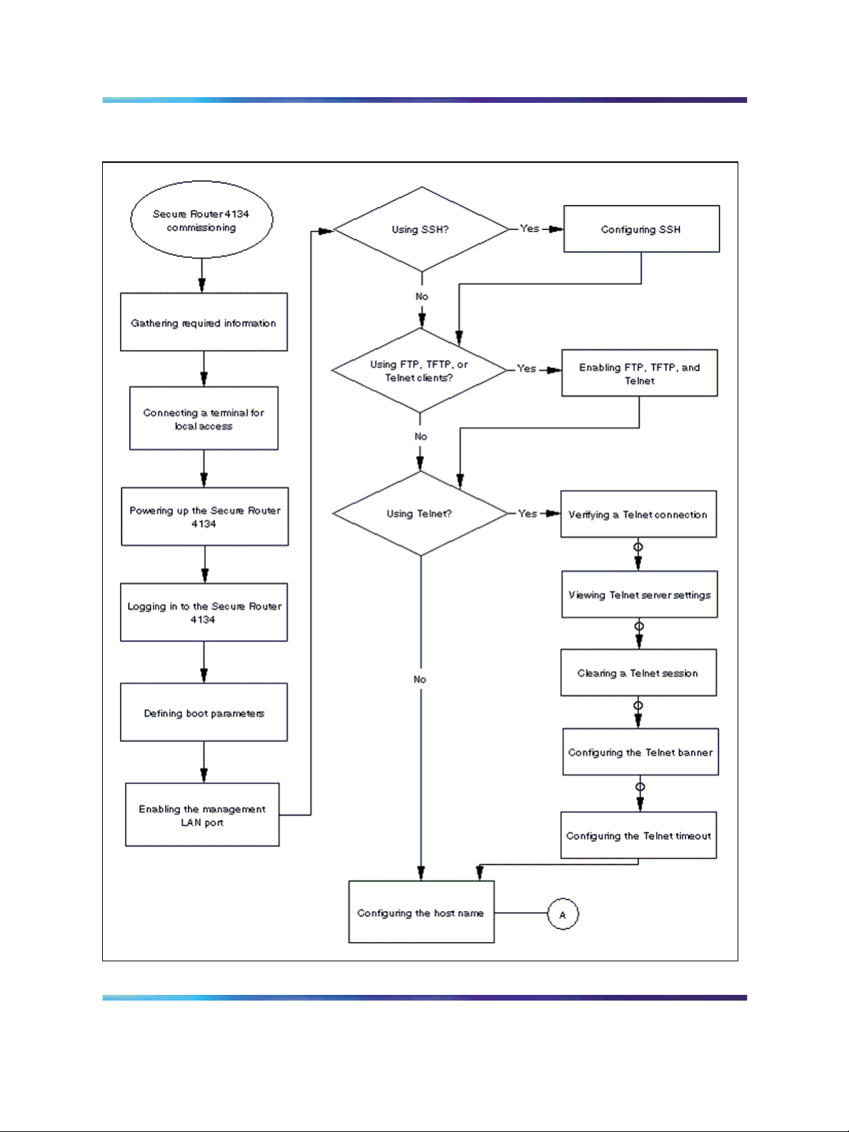
This task flow shows you the sequence of procedures you perform to
commission the Secure Router 4134. To link to any procedure, go to
"Secure Router 4134 commissioning navigation" (page 11).
9
Copyright © 2007, Nortel Networks
.
Nortel Secure Router 4134
Commissioning
NN47263-302 01.02 Standard
10.0 2 August 2007
Page 10
10 Secure Router 4134 commissioning
Figure 1
Secure Router 4134 commissioning procedures
Copyright © 2007, Nortel Networks
.
Nortel Secure Router 4134
Commissioning
NN47263-302 01.02 Standard
10.0 2 August 2007
Page 11
Secure Router 4134 commissioning navigation 11
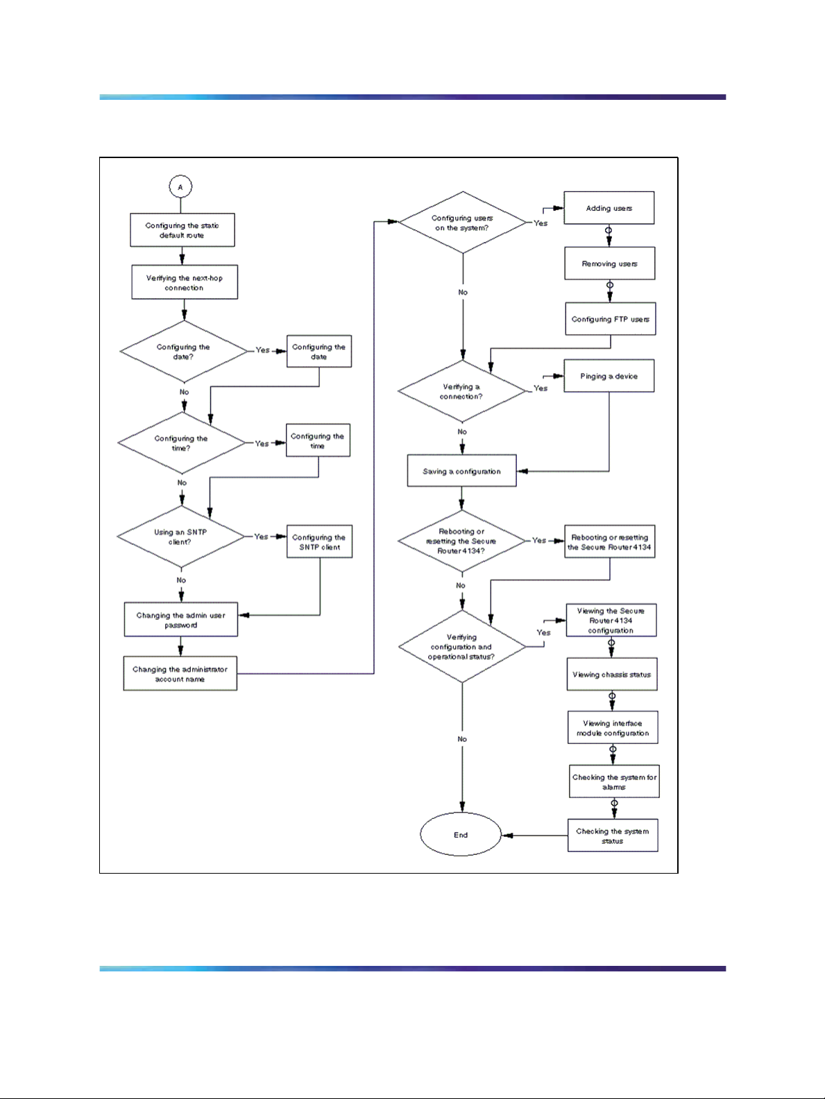
Figure 2
Secure Router 4134 commissioning procedures (continued)
Secure Router 4134 commissioning navigation
•
"Gathering required information" (page 13)
•
"Connecting a terminal for local access" (page 14)
Nortel Secure Router 4134
NN47263-302 01.02 Standard
Copyright © 2007, Nortel Networks
.
Commissioning
10.0 2 August 2007
Page 12

12 Secure Router 4134 commissioning
•
"Powering up the Secure Router 4134" (page 16)
•
"Logging in to the Secure Router 4134" (page 19)
•
"Defining boot parameters" (page 20)
•
"Enabling the management LAN port" (page 22)
•
"Configuring SSH" (page 24)
•
"Enabling FTP, TFTP, and Telnet" (page 25)
•
"Verifying the Telnet connection" (page 25)
•
"Viewing Telnet server settings" (page 26)
•
"Clearing a Telnet session" (page 26)
•
"Configuring the Telnet banner" (page 27)
•
"Configuring the Telnet timeout" (page 28)
•
"Configuring the host name" (page 29)
•
"Configuring the static default route" (page 29)
•
"Verifying the next-hop connection" (page 30)
• "Configuring the date" (page 30)
•
"Configuring the time" (page 31)
•
"Configuring the SNTP client" (page 32)
• "Changing the admin user password" (page 32)
•
"Changing the administrator account name" (page 33)
•
"Adding users" (page 34)
• "Removing users" (page 35)
•
"Configuring FTP users" (page 36)
•
"Pinging a device" (page 36)
•
"Saving a configuration" (page 37)
•
"Rebooting or resetting the Secure Router 4134" (page 37)
•
"Viewing the Secure Router 4134 configuration" (page 38)
•
"Viewing chassis status" (page 39)
•
"Viewing interface module configuration" (page 39)
•
"Checking the system for alarms" (page 39)
•
"Checking the system status" (page 40)
Copyright © 2007, Nortel Networks
.
Nortel Secure Router 4134
Commissioning
NN47263-302 01.02 Standard
10.0 2 August 2007
Page 13

Commissioning configuration
procedures
This section includes the recommended method to commission the Secure
Router 4134, while ensuring that you limit unauthorized access to the router.
Commissioning is the first step following hardware installation. The
commissioning task includes the initial procedures required to bring the
router online, and to configure appropriate access for remote users.
Gathering required information
Before you begin, gather all the information you require to complete the
commissioning steps.
Procedure steps
Step Action
13
1
Record all the required information for commissioning your Secure
Router 4134 in the following table.
Procedure job aid
Table 1
Gathering required information
Required information
New password for admin user kevx
Host name fremont
Management IP address and
mask
Copyright © 2007, Nortel Networks
.
Sample entries
10.11.12.13 255.255.255.0
NN47263-302 01.02 Standard
—End—
Record information here
Nortel Secure Router 4134
Commissioning
10.0 2 August 2007
Page 14

14 Commissioning configuration procedures
Required information
Next hop IP address for static
route to hosts and servers
IP address of hosts and
servers that access the Secure
Router 4134
The following figure is an example of a commissioning scenario showing
the basic configuration requirements including host name, management
interface, and terminals.
Figure 3
Commissioning scenario
Sample entries
11.12.13.14/24
a.b.c.d/32
Record information here
Connecting a terminal for local access
Connect a local terminal to the console port on the rear panel of the Secure
Router 4134. This local connection provides communication with the system
during commissioning.
Nortel Secure Router 4134
NN47263-302 01.02 Standard
Copyright © 2007, Nortel Networks
.
Commissioning
10.0 2 August 2007
Page 15

When powering up for the first time, Nortel recommends that you use a direct
console connection to the Secure Router 4134. After you have completed the
initial configuration, you can use a remote connection for router management.
Prerequisites
•
You have a PC running HyperTerminal or similar terminal emulation
program with the following communication protocol settings:
— 9600 bps
— 8 data bits
— 1 stop bit
— No flow control
— No parity
•
Ensure you have the supplied console cable (shipped with the chassis).
•
Ensure you have the supplied female DB-9 to RJ-45 adapter if you
require it for connection to your terminal or PC.
Connecting a terminal for local access 15
ATTENTION
•
Ensure you have the Secure Router 4134 securely installed in the
equipment rack.
Procedure steps
Step Action
1
Insert the male RJ-45 connector in the console port on the rear
panel of the Secure Router 4134.
2
Connect the female DB-9 to RJ-45 adapter to the opposite end of
the console cable, if necessary.
3
Insert the RJ-45 or female DB-9 connector (dependent on your
equipment) in a terminal or PC.
—End—
Procedure job aid
The following figure shows how to connect a terminal for local access.
Copyright © 2007, Nortel Networks
.
Nortel Secure Router 4134
Commissioning
NN47263-302 01.02 Standard
10.0 2 August 2007
Page 16

16 Commissioning configuration procedures
Figure 4
Connect a local terminal to the Secure Router 4134
Powering up the Secure Router 4134
Power up the Secure Router 4134 to initiate the power-on diagnostics test.
The Secure Router 4134 indicates the resulting pass or fail with status
LEDs, and by logging results in the event log.
Average time for the Secure Router to boot up: 5 minutes.
Prerequisites
•
The Secure Router 4134 is securely mounted and grounded. For
information about installing the Secure Router 4134 chassis, see Nortel
Secure Router 4134 Installation — Chassis (NN47263-300). For
information about installing the power supplies, interface modules, and
other hardware components, see Nortel Secure Router 4134 Installation
— Hardware Components (NN47263-301).
•
Power cables for AC power supplies are connected.
•
DC power for DC power supplies is connected.
•
A local terminal is connected to the Secure Router 4134 console port
(the console port is located on the rear panel of the router).
•
Ensure you have powered up the terminal or PC.
DANGER
Risk of electric shock
Ensure the Secure Router 4134 is properly grounded. For
information about grounding the Secure Router 4134, see Nortel
Secure Router 4134 Installation — Chassis (NN47263-300)
Copyright © 2007, Nortel Networks
.
Nortel Secure Router 4134
Commissioning
NN47263-302 01.02 Standard
10.0 2 August 2007
Page 17

Powering up the Secure Router 4134 17
ATTENTION
When powering up for the first time, Nortel recommends that you use a direct
console connection to the Secure Router 4134. After you have completed the
initial configuration, you can use a remote connection for router management.
Procedure steps (AC power)
Step Action
1
Turn on one power switch at a time (if you installed two AC power
supplies). Power switches are on the rear panel of the Secure
Router 4134.
The fans start immediately, and the LEDs cycle.
2
Verify that diagnostic testing is underway by observing the startup
messages on your local terminal.
3
4
Procedure steps (DC power)
Step Action
1
Copyright © 2007, Nortel Networks
.
Once the router completes the self-diagnostics tests, verify that the
System LED and the power LEDs that correspond to the power
supplies installed on your router (PS0 and PS1) are green.
Verify that the fan LED on the rear panel of the Secure Router 4134
is green, and air is flowing through the unit.
—End—
Turn on the DC power source.
The fans start immediately, and the LEDs cycle.
Nortel Secure Router 4134
Commissioning
NN47263-302 01.02 Standard
10.0 2 August 2007
Page 18

18 Commissioning configuration procedures
2
Verify that diagnostic testing is underway by observing the startup
messages on your local terminal.
3
Once the router completes the self-diagnostics tests, verify that the
System LED and the power LEDs that correspond to the power
supplies installed on your router (PS0 and PS1) are green.
4
Verify that the fan LED on the rear panel of the Secure Router 4134
is green, and air is flowing through the unit.
—End—
For troubleshooting information, see Nortel Secure Router 4134 —
Troubleshooting (NN47263-700).
When the Secure Router 4134 begins powering up, the boot sequence
displays messages on the terminal or PC that you connected to the console
port. A prompt displays at the beginning of the boot sequence indicating
that you can stop the auto-boot sequence by pressing any key. The Secure
Router 4134 waits for 5 seconds for input from you before beginning the
boot sequence. If you press a key and stop the auto-boot sequence, the
Secure Router 4134 displays the bootrom command menu. The following
figure shows the prompt to stop the auto-boot sequence and enter the
bootrom command area.
Copyright © 2007, Nortel Networks
.
Nortel Secure Router 4134
Commissioning
NN47263-302 01.02 Standard
10.0 2 August 2007
Page 19

Figure 5
Accessing the bootrom command menu
Logging in to the Secure Router 4134 19
If you accidentally enter the bootrom command menu, you can exit that
command menu and restart the normal boot sequence by pressing @ on
your keyboard.
For detailed information on using the bootrom command menu, see Nortel
Secure Router 4134 — Troubleshooting (NN47263-700).
Logging in to the Secure Router 4134
The first time you log on to the Secure Router 4134 CLI, you perform initial
configuration such as the following:
•
Configure the IP address for the management port.
•
Configure the next-hop (gateway IP address).
•
Enable remote access.
Use the procedure in this section to log on to the Secure Router 4134 for
the first time.
Copyright © 2007, Nortel Networks
.
Nortel Secure Router 4134
Commissioning
NN47263-302 01.02 Standard
10.0 2 August 2007
Page 20

20 Commissioning configuration procedures
Prerequisites
•
You have securely mounted the Secure Router 4134 in an equipment
rack.
•
You have connected a local terminal to the console port on the rear
panel of the Secure Router 4134.
•
You have powered up the Secure Router 4134.
•
The boot sequence is complete.
Procedure steps
Step Action
1
To log on to the Secure Router 4134 CLI for the first time, enter the
default user name and password:
login: admin
password: setup
Defining boot parameters
You can configure boot parameters for the Secure Router 4134. The Secure
Router 4134 provides two bootrom images for redundancy:
•
normal bootrom—the default boot image saved in the normal boot area,
and used as your working bootrom image
• golden bootrom—the backup boot image saved in the golden boot area,
and used if the normal bootrom image is corrupted
Procedure steps
Step Action
1
To access configuration mode, enter:
configure terminal
—End—
2
Copyright © 2007, Nortel Networks
.
To define the boot parameters, enter:
boot_params
—End—
Nortel Secure Router 4134
Commissioning
NN47263-302 01.02 Standard
10.0 2 August 2007
Page 21

Example of defining boot parameters
Step Action
Defining boot parameters 21
1
Access configuration mode:
configure terminal
2
Define boot parameters:
boot_params
The router returns the following:
WARNING : Configuration changes not yet saved!
3 When prompted, enter the name of the device from which you prefer
the router boots:
Boot dev [ftp,cf0,cf1,usb0]: cf0
4
Enter the boot file name (the router provides this information if you
have previously configured it):
Boot file name: SR4134.Z
5
Enter the name of the server you use (the router provides this
information if you have previously configured it):
Server name: sunserver
6
Enter the server IP address (the router provides this information if
you have previously configured it):
Server IP address: 10.10.11.12
7
Enter the router IP address (the router provides this information if
you have previously configured it):
My IP address: 10.10.13.14
8
9
10
11
12
Copyright © 2007, Nortel Networks
.
Enter the subnet mask (the router provides this information if you
have previously configured it):
My subnet mask: 255.255.255.0
Enter the gateway IP address (the router provides this information if
you have previously configured it):
Gateway IP address: 10.10.15.16
Enter your user name and password:
User name: kevx
Password: kevx
Enter 0 to disable or 1 to enable the checksum feature:
Checksum enable [0:Disable,1:Enable]: 1
Enter 0 to disable or 1 to enable the display of the image header
contents:
Show header enable [0:Disable,1:Enable]: 1
Nortel Secure Router 4134
Commissioning
NN47263-302 01.02 Standard
10.0 2 August 2007
Page 22

22 Commissioning configuration procedures
13
Enter the number (0, 1, or 2) that corresponds to the type of bootrom
image update that you prefer, or enter 3 if you prefer to not update
the bootrom image:
Save bootrom image [0:AutoUpdate,1:NormalBTupd,2:GoldenBTupd,3:NoUpd]: 0
If you select 0, 1, or 2, the router returns the following:
BOOT PARAMETERS HAVE BEEN SAVED.
14 Reboot the Secure Router 4134 to activate changes, or continue
with your configuration:
DO YOU WANT TO REBOOT: (Y/N) ? y
—End—
Viewing boot parameters and software image information
Use the procedures in this section to view the boot parameters configuration
and to display information for the normal and golden bootrom images.
Procedure steps
Step Action
1
To view the boot parameters configuration, enter
show boot_params
2
To view bootrom image information, enter:
file show_boot
Enabling the management LAN port
Enable the management Local Area Network (LAN) port on the Secure
Router 4134 for network management access. To enable the management
port, you assign it an IP address.
The Secure Router 4134 management Ethernet interface (FE 0/0) on the rear
panel does not support jumbo frames. Therefore, the management port Maximum
Transmission Unit (MTU) can be configured with a value in the range of 64 to
1500 bytes.
The following figure shows the location of the management port on the rear
panel of the Secure Router 4134.
—End—
ATTENTION
Copyright © 2007, Nortel Networks
.
Nortel Secure Router 4134
Commissioning
NN47263-302 01.02 Standard
10.0 2 August 2007
Page 23

Enabling the management LAN port 23
Figure 6
Management port on the rear panel of the Secure Router 4134
Prerequisites
•
You must be connected to the Secure Router 4134 through the console
port. See "Connecting a terminal for local access" (page 14) for
information about connecting a terminal to the console port.
•
You must log in as a user with sufficient permissions to configure the
Secure Router 4134.
•
You must have the IP address and netmask that you want to assign
to the management port.
The following procedure uses Ethernet port 0/0 (on the rear of the Secure
Router 4134) for the management port. You can also use port 0/1 or port
0/2 on the front panel of the Secure Router 4134 for management purposes.
Ethernet port 0/0 is a 10/100 Base-T port. Ethernet ports 0/1 and 0/2 are
10/100/1000 Base-T ports.
Procedure steps
Step Action
1 To access configuration mode, enter:
Copyright © 2007, Nortel Networks
.
Nortel Secure Router 4134
Commissioning
NN47263-302 01.02 Standard
10.0 2 August 2007
Page 24

24 Commissioning configuration procedures
configure terminal
2
To identify the management port for configuration, enter:
interface ethernet 0/0
3 To configure the management port IP address, enter:
ip address <ipaddr> <netmask>
—End—
Table 2
Variable definitions
Variable Value
<ipaddr> The IP address that you assign to the
management port. For example, 10.11.12.13.
<netmask> The network mask that you assign to the
management port IP address. For example,
255.255.255.0.
Configuring SSH
You can enable an SSH connection for remote access. To generate a key
and enable SSH, use the procedures in this section.
Procedure steps
Step Action
1
2
3
4
5
6
7
To access configuration mode, enter:
configure terminal
To access the SSH key generation subtree, enter:
ssh_keygen
To generate the DSA key, enter:
generate dsa
To generate the RSA key, enter:
generate rsa
To exit the SSH key generation subtree, enter:
exit
To enable the SSH connection, enter:
ssh_server
enable
To save the configuration, enter:
Copyright © 2007, Nortel Networks
.
Nortel Secure Router 4134
Commissioning
NN47263-302 01.02 Standard
10.0 2 August 2007
Page 25

save local
Enabling FTP, TFTP, and Telnet
The default configuration for the Secure Router 4134 includes FTP, TFTP,
and Telnet servers disabled. You can enable any and all of these servers to
allow this type of access to the Secure Router 4134.
Prerequisites
•
You must assign an IP address to the Secure Router 4134.
Procedure steps
Step Action
Verifying the Telnet connection 25
—End—
1
To access configuration mode, enter:
configure terminal
2
To enable the FTP service, enter:
ftp_server
3
To enable the TFTP service, enter:
tftp_server
4
To enable the Telnet service, enter:
telnet_server
Verifying the Telnet connection
Verify the Telnet connection to ensure that users can successfully access
the Secure Router 4134 using remote access.
Prerequisites
•
The IP address of the management interface on the Secure Router
4134 must be configured.
—End—
•
You must havethe IP address of the management interfaceon the router.
•
You must have a terminal or workstation connected to the Ethernet LAN.
Copyright © 2007, Nortel Networks
.
Nortel Secure Router 4134
Commissioning
NN47263-302 01.02 Standard
10.0 2 August 2007
Page 26

26 Commissioning configuration procedures
Procedure steps
Step Action
1
To start a Telnet session from your workstation, enter:
telnet <ipaddr>
2
To log in, enter:
login: admin
password: setup
Viewing Telnet server settings
View the Telnet server settings for information about the status of the Telnet
server (enabled or disabled) and the Telnet session timeout value.
Procedure steps
Step Action
1
To view information about the Telnet server settings, enter:
show telnet
—End—
—End—
Clearing a Telnet session
You can disconnect a specific Telnet session, if necessary, or you can
disconnect all Telnet sessions simultaneously.
Procedure steps
Step Action
1
Copyright © 2007, Nortel Networks
.
To view the list of users currently connected using a Telnet session
to find the Telnet session sequence numbers, enter:
show users
The following figure shows an example of the Telnet session
sequence numbers for users remotely connected to the router.
NN47263-302 01.02 Standard
Nortel Secure Router 4134
Commissioning
10.0 2 August 2007
Page 27

Configuring the Telnet banner 27
2
To clear a specific Telnet session, enter:
clear telnet_session <value>
—End—
Table 3
Variable definitions
Variable Value
<value> The Telnet session sequence number. Enter
a value from 1 to 16.
To quickly disconnect all Telnet sessions, use the command:
clear telnet_sessions
Configuring the Telnet banner
You can customize the banner that appears when users access the router
using Telnet services. When configuring the Telnet banner, use \n to begin
a new line.
Procedure steps
Step Action
1
2
Copyright © 2007, Nortel Networks
.
To access configuration mode, enter:
configure terminal
To configure the Telnet banner, enter:
telnet_banner banner <string> [banner1] [banner2]
—End—
Nortel Secure Router 4134
Commissioning
NN47263-302 01.02 Standard
10.0 2 August 2007
Page 28

28 Commissioning configuration procedures
Table 4
Variable definitions
Variable Value
[banner1] An optional parameter that you use to extend
the banner text. If you require the banner text
be more than 255 characters in length, use
banner1 <string> to continue the banner
text.
[banner2] An optional parameter that you use to extend
the banner text.
<string> The banner text that you want to appear in
Telnet sessions. The banner text can be up to
255 characters in length. Use \n to begin a
new line within the banner.
Configuring the Telnet timeout
You can configure the timeout value for Telnet sessions. A Telnet session
disconnects if it remains inactive for the configured session duration.
Procedure steps
Step Action
1
2
Table 5
Variable definitions
Variable Value
<value> Enter the time in seconds (from 0 to 3600) after
To access configuration mode, enter:
configure terminal
To configure the Telnet timeout value, enter:
telnet_timeout <value>
—End—
which inactive Telnet sessions automatically
disconnect. The default value is 900 seconds. If
you enter a value of 0 seconds, inactive Telnet
sessions do not automatically disconnect.
Copyright © 2007, Nortel Networks
.
Nortel Secure Router 4134
Commissioning
NN47263-302 01.02 Standard
10.0 2 August 2007
Page 29

Configuring the host name
Configure a host name for the Secure Router 4134 to uniquely identify it.
Once assigned, the host name becomes the CLI prompt name.
Changing the host name later (that is, post commissioning), and committing this
change, drops all Telnet and SSH connections. All active console sessions also
end.
Procedure steps
Step Action
Configuring the static default route 29
ATTENTION
1
To access configuration mode, enter:
configure terminal
2
To configure the host name for the Secure Router 4134, enter:
hostname <WORD>
—End—
Table 6
Variable definitions
Variable Value
<WORD> The name you want to assign to the Secure
Router 4134.
Configuring the static default route
Configure a static route to specify a preferred route to a destination. You
can identify the gateway, or next-hop, for a static route by specifying one
of the following:
•
IP address of a directly connected interface
•
name of a local interface such as ethernet0/0
Procedure steps
Step Action
1
2
Copyright © 2007, Nortel Networks
.
To access configuration mode, enter:
configure terminal
To configure the gateway route, enter:
ip route <netaddr/mask> <gateway>
—End—
Nortel Secure Router 4134
Commissioning
NN47263-302 01.02 Standard
10.0 2 August 2007
Page 30

30 Commissioning configuration procedures
Table 7
Variable definitions
Variable Value
<netaddr/mask> The IP address and the subnet mask of
the destination network. For example,
11.12.13.14/24.
Entering the subnet mask is optional.
<gateway>
The IP address or interface name of the
gateway. For example, 10.11.12.16.
Verifying the next-hop connection
Use the procedure in this section to verify that the connection from the
management interface successfully connects to the next-hop device.
Prerequisites
•
You must have the IP address of the next-hop device.
Procedure steps
Step Action
1
To ping the next-hop device, enter:
ping <ipaddr>
Configuring the date
To configure the date, you enter the month, day, and year.
Procedure steps
Step Action
1
2
To access configuration mode, enter:
configure terminal
To configure the date, enter:
date <month> <day> <year>
—End—
—End—
Copyright © 2007, Nortel Networks
.
Nortel Secure Router 4134
Commissioning
NN47263-302 01.02 Standard
10.0 2 August 2007
Page 31

Configuring the time 31
Table 8
Variable definitions
Variable Value
<day> The current day in relation to the month. Enter
a value from 1 to 31.
<month> The current month. Enter a value from 1 to 12.
<year>
The current year. Enter a value from 2000 to
2100.
Configuring the time
To set the current time for the Secure Router 4134, you specify the time in
relation to Coordinated Universal Time (UTC):
•
time zone offset — ahead (+) or behind (-) UTC
•
number of hours ahead or behind UTC
•
number of minutes ahead or behind UTC
Procedure steps
Step Action
1
2
Table 9
Variable definitions
Variable Value
<+|-> The time zone offset. Enter + to indicate that
To access configuration mode, enter:
configure terminal
To configure your local time, enter:
utc <+|-> <hour offset> <minute offset>
—End—
your time zone is ahead of UTC. Enter - to
indicate that your time zone is behind UTC.
For example, if you are in New York, you enter
utc -.
Copyright © 2007, Nortel Networks
.
Nortel Secure Router 4134
Commissioning
NN47263-302 01.02 Standard
10.0 2 August 2007
Page 32

32 Commissioning configuration procedures
Variable Value
<hour offset> The number of hours that your local time is
offset from UTC. Enter a value from 0 to 23.
For example, if you are in New York, you enter
utc - 4.
<minute offset> The number of minutes that your local time is
offset from UTC. Enter a value from 0 to 59.
For example, if you are in New York, you enter
utc - 4 0.
Configuring the SNTP client
The Simple Network Time Protocol (SNTP) synchronizes the internal clocks
of various network devices across large, diverse networks to universal
standard time. Use the procedure in this section to enable the SNTP client
on the Secure Router 4134.
Procedure steps
Step Action
1 To access configuration mode, enter:
configure terminal
2
To set the location of the SNTP server, enter:
sntp server {ipaddr|hostname}
3 To set the timeout value for the response from the server, enter:
sntp timeout <value>
—End—
Table 10
Variable definitions
Variable Value
{ipaddr | hostname} The IP address or host name of the broadcast
server. The default value is any broadcast
server.
<value> The timeout value in seconds. The default
timeout value is 1024 seconds.
Changing the admin user password
The system administrator login consists of two components: the account
name and the password. The initial login name is always "admin". You can
change this after logging in for the first time. The default administrative
Copyright © 2007, Nortel Networks
.
Nortel Secure Router 4134
Commissioning
NN47263-302 01.02 Standard
10.0 2 August 2007
Page 33

password is "setup". Nortel recommends you change the default password
as soon as possible to ensure only authorized personnel can access the
Secure Router 4134.
Procedure steps
Step Action
Changing the administrator account name 33
1
To access password configuration mode, enter:
password
The Secure Router 4134 prompts you for the current user name.
2
Enter the default user name, which is the current user name:
admin
The Secure Router 4134 prompts you for the old password.
3
Enter the default password, which is the current password:
setup
The Secure Router 4134 prompts you for the new password.
4
Enter your new password.
The Secure Router 4134 prompts you to verify the new password.
5
Re-enter your new password.
A message appears that confirms that the password is changed.
—End—
Changing the administrator account name
Use the procedure in this section to change the administrator login name
(Level 1 access) to a user-specified name. The default login name for the
Secure Router 4134 is "admin". The administrator login name can be from 3
to 39 characters in length.
Procedure steps
Step Action
1
2
Copyright © 2007, Nortel Networks
.
To access configuration mode, enter:
configure terminal
To change the login name, enter:
admin_name <WORD>
The Secure Router 4134 displays a message that confirms the login
name is successfully changed.
—End—
Nortel Secure Router 4134
Commissioning
NN47263-302 01.02 Standard
10.0 2 August 2007
Page 34

34 Commissioning configuration procedures
Adding users
You can identify users (that is, login names) who can access the Secure
Router 4134, and assign each user an access privilege (levels 2–4). Only
the system administrator (level 1 access) can add, modify, or remove this
information from the system.
Procedure steps
Step Action
1
To access configuration mode, enter:
configure terminal
2
Enter the user name and access level:
user <username> level <value>
The Secure Router 4134 prompts you to enter a password for this
user.
3
Enter a password (from 0 to 10 characters) for the new user.
The Secure Router 4134 prompts you to re-enter the password.
4
Re-enter the password for the new user.
The Secure Router 4134 confirms that the password is set and
confirms the name of the new user is added.
Table 11
Variable definitions
Variable Value
<username>
—End—
The user name you want to add to the Secure
Router 4134. The user name can contain up
to 39 characters.
<value> The access level assigned to the user. Values
are 2–4. The lower the access level value, the
higher the access privileges. For example,
a user with an access level of 2 has more
privileges than a user with an access level 3
or 4.
Nortel Secure Router 4134
NN47263-302 01.02 Standard
Copyright © 2007, Nortel Networks
.
Commissioning
10.0 2 August 2007
Page 35

Removing users 35
Procedure job aid
The CLI supports four levels of privilege for users. The following table
defines each level.
Table 12
CLI user access levels
Privilege level Privilege name Definition
1 (highest) PRIVILEGE_ADMIN Admin level can access any
command and configure
any feature in the router,
including user configuration
and administration.
2
3
PRIVILEGE_CONFIGURE Configure level can configure
any feature. Cannot add or
delete users.
PRIVILEGE_TEST Test level can only run
diagnostic tests. Cannot
access configuration
commands.
4 (lowest) PRIVILEGE_NORMAL Normal level can only enter
show or display commands.
Removing users
The system administrator can remove configured user names from the
Secure Router 4134.
ATTENTION
To reset a user password, you must delete and then recreate the user account.
Procedure steps
Step Action
1
2
To access configuration mode, enter:
configure terminal
To remove a user, enter:
no user <username>
—End—
Copyright © 2007, Nortel Networks
.
Nortel Secure Router 4134
Commissioning
NN47263-302 01.02 Standard
10.0 2 August 2007
Page 36

36 Commissioning configuration procedures
Configuring FTP users
Procedure steps
Step Action
1 To access configuration mode, enter:
configure terminal
2
3 At the prompt, enter a password for the FTP user:
4
Pinging a device
Ping a device to verify the connection between the Secure Router 4134 and
that network device. If the network device sends a ping reply, a message
indicates that the specified IP address is alive and can communicate with
the router. If the router does not receive a reply, the message indicates
that the address is not responding.
Prerequisites
To configure an FTP user, enter a user name:
ftp_user <username>
Please enter new password: <password>
At the prompt, re-enter the password:
Please re-enter password: <password>
If you entered the password correctly, the Secure Router returns a
message indicating a successful configuration:
password is set
—End—
•
You must physically connect the Secure Router 4134 to the network.
•
You must physically connect the specific network device to the network.
Procedure steps
Step Action
1
Copyright © 2007, Nortel Networks
.
Ping the network device:
ping <ipaddr>
—End—
Nortel Secure Router 4134
Commissioning
NN47263-302 01.02 Standard
10.0 2 August 2007
Page 37

Saving a configuration
Issue the save command to save the running configuration to a file. You can
save the configuration to the local file system, or to a file on the network.
Procedure steps
Step Action
Rebooting or resetting the Secure Router 4134 37
1
To save the configuration to the local file system, enter:
save local [file <filename>]
2
To save the configuration to a network file, enter:
save network <ipaddr> <path>
—End—
Table 13
Variable definitions
Variable Value
[file <filename>] The name of the file to which the configuration
is saved. This is an optional parameter. The
configuration is saved to the system default file
(system.cfg) if you do not specify a filename.
<ipaddr> TheIP address of the device on which you store
the network configuration file.
<path> The full path of the remote configuration file.
Rebooting or resetting the Secure Router 4134
Reset and reboot the Secure Router 4134 properly to avoid file system
corruption. Resetting the router returns it to a factory-default configuration.
Rebooting the router shuts down and restarts the system. The procedure in
this section shows you how to reset the configuration on the Secure Router
4134, reboot the router to restore the factory-default settings, and save the
factory-default settings to the configuration file.
Procedure steps
Step Action
1
2
3
Copyright © 2007, Nortel Networks
.
To access configuration mode, enter:
configure terminal
To reset the Secure Router 4134, enter:
system reset-to-factory {system|users}
To reboot the Secure Router 4134, enter:
Nortel Secure Router 4134
Commissioning
NN47263-302 01.02 Standard
10.0 2 August 2007
Page 38

38 Commissioning configuration procedures
reboot
4
When the Secure Router 4134 completes the reboot, save the
factory-default settings to the system.cfg file by entering:
save local
—End—
Table 14
Variable definitions
Variable Value
{system | users} Enter system to remove all information stored
in memory, which includes user information,
event logs, crash logs, command logs, and boot
parameters.
Enterusers to remove allusersandinformation
related to users.
Viewing the Secure Router 4134 configuration
View the Secure Router 4134 configuration to understand the current state
of the system software.
For more information about using commands, see Nortel Secure Router
4134 — Using the Command Line Interface (NN47263-506). For a complete
list of CLI commands, see Nortel Secure Router 4134 — Command Line
Reference (NN47263-507).
Procedure steps
Step Action
1
2
Copyright © 2007, Nortel Networks
.
To view the current configuration, enter:
show configuration running
You can also enter show running-config to view the current
configuration.
To view the configuration that is stored in Flash, enter:
show configuration stored
You can also enter show startup-config to view the stored
configuration.
—End—
Nortel Secure Router 4134
Commissioning
NN47263-302 01.02 Standard
10.0 2 August 2007
Page 39

Viewing chassis status
Use the procedure in this section to view summary information about the
Secure Router 4134 chassis, including its operational status. After you
install interface modules, you can use the show chassis command to
verify that the Secure Router 4134 recognizes the modules.
Procedure steps
Step Action
Checking the system for alarms 39
1
To view summary information about the Secure Router 4134, enter:
show chassis
—End—
Viewing interface module configuration
Use the procedure in this section to quickly check the state and configuration
of installed interface modules.
Procedure steps
Step Action
1
2
To view the configuration of interface modules installed in your
Secure Router 4134, enter:
show module configuration all
To view the configuration of individual interface modules, enter:
show module configuration [t1|e1|ct3|
serial|hssi|t3] <slot/port>
—End—
Checking the system for alarms
The Secure Router 4134 reports alarms when it detects irregular conditions
in incoming signals to the interface modules. Use the show module
alarms command to quickly check for any irregularities.
Procedure steps
Step Action
1 To view the current alarms for any T1 WAN link on the Secure
Router 4134, enter:
show module alarms t1 <slot/port>
Nortel Secure Router 4134
NN47263-302 01.02 Standard
Copyright © 2007, Nortel Networks
.
Commissioning
10.0 2 August 2007
Page 40

40 Commissioning configuration procedures
2
To view the current alarms for any E1 port on the Secure Router
4134, enter:
show module alarms e1 <slot/port>
3
To view the current alarms for any CT3 port on the Secure Router
4134, enter:
show module alarms ct3 <slot/port>
4
To view the current alarms for any serial port on the Secure Router
4134, enter:
show module alarms serial <slot/port>
5
To view the current alarms for any HSSI port on the Secure Router
4134, enter:
show module alarms hssi <slot/port>
6
To view the current alarms for any T3 port on the Secure Router
4134, enter:
show module alarms t3 <slot/port>
Checking the system status
You can view the operating status and current configuration of each WAN,
Ethernet, or serial interface using the show module configuration
command. Refer to Nortel Secure Router 4134 — Command Line
Reference (NN47263-507) for a complete list of CLI commands for the
Secure Router 4134.
—End—
Procedure steps
Step Action
1
Copyright © 2007, Nortel Networks
.
View the operating status of all installed interface modules:
show module configuration all
—End—
Nortel Secure Router 4134
Commissioning
NN47263-302 01.02 Standard
10.0 2 August 2007
Page 41

Page 42

Nortel Secure Router 4134
Commissioning
Copyright © 2007 , Nortel Networks
All Rights Reserved.
Publication: NN47263-302
Document status: Standard
Document version: 01.02
Document date: 2 August 2007
To provide feedback or report a problem in this document, go to w
This document is protected by copyright laws and international treaties. All information, copyrights and any other intellectual
property rights contained in this document are the property of Nortel Networks. Except as expressly authorized in writing by Nortel
Networks, the holder is granted no rights to use the information contained herein and this document shall not be published, copied,
produced or reproduced, modified, translated, compiled, distributed, displayed or transmitted, in whole or part, in any form or media.
Sourced in Canada, the United States of America, and India.
Nortel, the Nortel logo, and the Globemark are trademarks of Nortel Networks.
All other trademarks are the property of their respective owners.
ww.nortel.com/documentfeedback
 Loading...