

Page 1

Part No. 209664-A
June 2000
4100 Guardian Street
Simi Valley CA 93063-3382 USA
Getting Started with Passport 4400, Release 4.1
Page 2

2
Copyright © 2000 Nortel Networks, Inc.
All rights reserved. Printed in the USA. June 2000.
The information in this document is subject to change without not ice. The statements, configurations, technical
data, and recommendations in this document are believed to be accurate and reliable, but are presented without
express or implied warranty. Users must take full responsibility for their applications of any products specified in
this document. The information in this document is proprietary to Nortel Networks, Inc.
The software described in this document is furnished under a license agreement and may only be used i n
accordance with the terms of that license. A summary of the Software License is included in this document.
Trademarks
Quick2Config, Marathon, Passport, and Nortel Networks are registered t r ademarks and are trademarks of Nortel
Networks, Inc.
Microsoft, MS, MS-DOS, Win32, Windows, and Windows NT are registered trademarks of Microsoft Corporation.
All other trademarks and registered trademarks are the property of their respective owners.
Restricted Rights Legend
Use, duplication, or disclosure by the United States Government is sub ject to restrictions as set forth in
subparagraph (c)(1)(ii) of the Rights in Technical Data and Computer Software clause at DFARS 252.227-7013.
Notwithstanding any other license agreement that may pertai n to, or accompany the delivery of , thi s computer
software, the rights of the United States Government regarding its use, reproduction, and disclosure are as set forth
in the Commercial Computer Software-Restricted Rights clause at FAR 52.227-19.
Statement of Conditions
In the interest of improving internal design, operational function, and/or reliability, Nortel Networks, Inc. reserves
the right to make changes to the products described in this document without notice.
Nortel Network s, In c. do es not as sume any liabil ity tha t ma y oc cur d ue to the use or ap plic ation of the p roduc t(s) o r
circuit layout(s) described herein.
Portions of the code in this software product may be Copyright © 2000, Regents of the University of California. All
rights reserved. Redistribution and use in source and binary forms of such portions are permitted, provided that the
above copyright notice and this paragraph are duplicated in all such forms and that any documentation, advertising
materials, and other ma terials related to such distribution and use acknowledge that such portions of the software
were developed by the University of California, Berkeley. The name of the University may not be used to endorse
or promote products derived from such portions of the software without specific prior written permission.
SUCH PORTIONS OF THE SOFTWARE ARE PROVIDED “AS IS” AND WITHOUT ANY EXPRESS OR
IMPLIED WARRANTIES, INCLUDING, WITHOUT LIMITATION, THE IMPLIED WARRANTIES OF
MERCHANT ABILIT Y AND FITNESS FOR A PARTICULAR PURPOSE.
In addition, the program and information contained herein are licensed only pursuant to a license agreement that
contains restrictions on use an d disclosure (that may incorporat e by reference certain limitations and notices
imposed by third parties).
209664-A
Page 3

EC Declaration of Conformity
This product conforms (or these products conform) to th e provisions of Council Directive 89/336/EEC and 73/23/
EEC. The Declaration of Conformity is available at Nortel Networks, 4100 Guardian Street Simi Valley, CA 93065
attention: Regulatory Department.
LIMITATIONS OF REMEDIES
Nortel’s entire liability and Customer’s exclusive remedies are as follows: Nortel shall (i) use commercially
reasonable efforts to correct any failure of the software program, of which it is given written notice by Customer
during the Warranty Period, to perform substantially in accordance with the documentation, provided such failure
can be recreated by Nortel in an unmodified version of the software program, or if Nortel is un able to correct such
failure the software program and documentation may be returned and the license fee paid will be refunded, or (ii)
replace any diskette not meeting Nortel’s “Limited Warranty” or, if Nortel is unable to deliver a replacement
diskette which is free from defects in material s or workmanship, the softw a r e pr ogram and documentat ion may be
returned and the license fee paid will be refunded.
IN NO EVENT WILL NORTEL OR ITS SUPPLIERS BE LIABLE TO CUSTOMER FOR ANY LOST
PROFILES, LOST SAVINGS OR OTHER INCIDENTAL OR CONSEQUENTIAL DAMAGES ARISING OUT
OF THE USE OR INABILITY TO USE THE PROGRAM EVEN IF NORTEL HAS BEEN ADVISED OF THE
POSSIBLITY OF SUCH DAMAGES. THE LIABILITY OF NORTEL, IF ANY, FOR DAMAGES RELATING
TO ANY NORTEL SOFTWARE PRODUCT SHALL BE LIMITED TO THE ACTUAL AMOUNTS PAID BY
CUSTOMER FOR SUCH SOFTWARE PRODUCT.
SOME STATES DO NOT ALLOW THE EXCLUSION OF IMPLIED WARRANTIES OR THE LIMITATION
OR EXCLUSION OF LIABILITY FOR INCIDENTAL OR CONSEQUENTIAL DAMAGES, SO THE ABOVE
EXCLUSIONS OR LIMITATION MAY NOT APPLY.
3
Getting Started with Passport 4400, Release 4.1
Page 4

4
Safety Warnings and Cautions
Various safety agencies request statements of warning or caution to help you in the safe operation of the unit.
These statements also apply to any and all modules installed within the unit.
To ensure adequate cooling of the
equipment a 2.0 inch unobstructed
space must be maintained around all
sides of the unit.
The ac power socket shall be installed
near the equipment and shall be easily
accessible.
Um die Kühlung des Gerätes nicht zu
beschränken, is t es notwendig um das
Gerät herum an allen Seiten ca 5 cm
Raum zu lassen.
Stellen Sie das Gerät in der Nähe einer
geerdeten Schutzkontakt- steckdose
so auf, dass diese leicht erreichbar und
Pour assurer un refroidissement
adéquat, maintenir un espace libre de
5 cm (2 pouces) tout auto ur de
l’appareil.
Installer la prise AC à proximité de
l’appareil, dans un rayon d’accès
facile.
zugänglich ist.
Installation and access to the interior
of this unit shall be made only by a
qualified technician.
Connection to the network is to be
disconnected before the (mains) plug
is removed.
Die Montage und der Zugang ins
Innere des Gerätes sind nur einem
qualifizierten Te chniker gestattet.
Ehe der Netzstecker aus der Steckdose
gezogen wird, müssen sämtliche
äusserliche Verbindungen vom Gerät
getrennt werden.
L’installation et l’ouverture de cet
appareil est permise par un technicien
autorisé seulement.
Avant de débrancher la prise de
courant, assurer que toutes les
connexions externes ont été
déconnecté de l’appareil.
Warning Warnung Avertissement
Remove power plug from the power
socket before performing any service
work on the unit.
The power supply is auto-ranging in
this model.
The power supply cordset to be
supplied in Europe mu s t ha ve
2
mm, 3 conductor “HAR” cord
0.75
type H05VV-F, terminated in a
grounding type Shucko plug on one
end and a molded-on IEC 320
connector on the ot her end.
Vor öffnen des Gerätes, muss der
Netzstecker aus der Steckdose
gezogen werden.
Netzteil ist mit automatischer
Umschaltung entsprec hend der
Versorgungsspannung versorgt.
Die Netzleitung sollte ein
harmonisierter Typ (HAR) sein, mit
der Bezeichnung H05VV-F oder
H05VVH2-F, 3G 0.75
2
mm, mit einem
Schutzkontakt - und einem
Kaltgerätestecker (IEC 320).
Débrancher la prise de courant avant
d’entreprendre aucun travail de
réparation de l’appareil.
Ce modèle s’adapte automatiquement au courant électrique ou voltage
de la prise murale.
En Europe, brancher l’appareil à la
prise murale au moyen d’un fil
“HAR” comprenant 3 cable s
H05VV-F ou H05VVH2-F de
2
mm chacun, avec à une extremité
0.75
une prise de terre genre SHUCKO et à
l’autre une prise IEC 320.
Technical Data Technische Daten Donnees Te chniques
Passport 4400 Serie s
ac units
Input Voltage 100-240 Vac
-5%, +10%
Input Current: 3A/1.5A
Frequency: 47-63 Hz
dc units
Input Voltage 36-72 Vdc
Input Current: 5A
Passport 4400 Serie s
ac Geraete
Nennspannung: 100-240 V
-5%, +10%
Nennstrom: 3A/1.5A
Frequenz: 47-63 Hz
dc Geraete
Nennspannung: 36-72 V
Nennstrom: 5A
Passport 4400 Serie s
ac appareils
Vol ta ge d’Accès: 100-240 V
∼
Courant d’Accès: 3A/1.5A
Fréquence: 47-63 Hz
dc appareils
Vol ta ge d’Accès: 36-72 V
Courant d’Accès: 5A
209664-A
-5%, +10%
∼
Page 5

Notification of FCC Requirements
5
NOTE:
to Part 15 of the FCC Rules. These limits are designed to provide reasonable protection against harmful
interference when the equipment is operated in a commercial environment. This equipment generates, uses, and can
radiate radio frequency energy and, i f not installed and used in accordance with the instruction manual, ma y cause
harmful interference to radio communications. Operation of this equipment in a residential area is likely to cause
harmful interference in which case the user will be required to correct the interference at his own expense.
Changes or modifications to this product, that could increase the amount of Radio Frequency Emissions from this
product, without the expressed written approval of Nortel Networks could cause the product and the user to violate
the FCC’s Rules and Regulations, thus requiring the product to be turned off or disconnected.
If this unit is used on a DTE which requires use of shi el ded cables for compliance with FCC Part 15, then use of a
filtered pin connector may be required to maintain FCC compliance. See the Installation section for specific
applications.
This equipment has been tested and found to comply with the limits for a Class A digital d evic e, pur suant
Notification of Canadian Requirements
This digital apparatus does not e xce ed the Cla ss A limits for ra d io noise emissio ns from digita l app ara tus as set ou t
in the Radio Interfer ence Regulations of the Government of Canad a Department of Industry.
Le présent appareil numérique n’émet pas de bruits ra d ioélectriques dépassant les limites applicables a ux appare ils
numériques de classe A prescrites dans le règlement sur le brouillage radioélectrique édicté par le Ministère des
Industry du Canada.
Getting Started with Passport 4400, Release 4.1
Page 6

6
209664-A
Page 7

Contents
Chapter 1
Introduction . . . . . . . . . . . . . . . . . . . . . . . . . . . . . . . . . . . . . . . . . . . . . . . . . . 11
List of Documentation . . . . . . . . . . . . . . . . . . . . . . . . . . . . . . . . . . . . . . . . . . . . . . . . . 12
Unpacking the Unit . . . . . . . . . . . . . . . . . . . . . . . . . . . . . . . . . . . . . . . . . . . . . . . . . . . .12
Determining Which Management Tool to Use . . . . . . . . . . . . . . . . . . . . . . . . . . . . . . . 14
Device Management Tools . . . . . . . . . . . . . . . . . . . . . . . . . . . . . . . . . . . . . . . . . .14
Network Management Tools . . . . . . . . . . . . . . . . . . . . . . . . . . . . . . . . . . . . . . . . . 16
Chapter 2
Online Documentation. . . . . . . . . . . . . . . . . . . . . . . . . . . . . . . . . . . . . . . . . . 19
Accessing the Online Documentation . . . . . . . . . . . . . . . . . . . . . . . . . . . . . . . . . . . . . 19
Open the documentation . . . . . . . . . . . . . . . . . . . . . . . . . . . . . . . . . . . . . . . . . . . . 20
Navigating Online Documentation . . . . . . . . . . . . . . . . . . . . . . . . . . . . . . . . . . . . . . . . 21
Printing Online Documentation . . . . . . . . . . . . . . . . . . . . . . . . . . . . . . . . . . . . . . . . . . 25
Browsers . . . . . . . . . . . . . . . . . . . . . . . . . . . . . . . . . . . . . . . . . . . . . . . . . . . . . . . . . . . 25
7
Chapter 3
Hardware Setup . . . . . . . . . . . . . . . . . . . . . . . . . . . . . . . . . . . . . . . . . . . . . . . 29
Workstation Requirements . . . . . . . . . . . . . . . . . . . . . . . . . . . . . . . . . . . . . . . . . . . . . . 29
Installing Passport 4460 Hardware . . . . . . . . . . . . . . . . . . . . . . . . . . . . . . . . . . . . . . . 30
Chapter 4
Configurator Procedure for Creating a Node Profile . . . . . . . . . . . . . . . . . 31
Accessing the Configurator Through a Web Browser . . . . . . . . . . . . . . . . . . . . . . . . . 32
Viewing Node Profile Information . . . . . . . . . . . . . . . . . . . . . . . . . . . . . . . . . . . . . . . . . 33
Defining a Unique DNA Prefix . . . . . . . . . . . . . . . . . . . . . . . . . . . . . . . . . . . . . . . . . . .34
Defining a Node Name . . . . . . . . . . . . . . . . . . . . . . . . . . . . . . . . . . . . . . . . . . . . . . . . .35
Defining a Node ID . . . . . . . . . . . . . . . . . . . . . . . . . . . . . . . . . . . . . . . . . . . . . . . . . . . .36
Defining a Customer ID . . . . . . . . . . . . . . . . . . . . . . . . . . . . . . . . . . . . . . . . . . . . . . . .37
Getting Started with Passport 4400, Release 4.1
Page 8

8
Contents
Resetting the Unit . . . . . . . . . . . . . . . . . . . . . . . . . . . . . . . . . . . . . . . . . . . . . . . . . . . . . 37
Setting the DNA Numbering Plan . . . . . . . . . . . . . . . . . . . . . . . . . . . . . . . . . . . . . . . . . 38
Overriding the DNA Numbering Plan . . . . . . . . . . . . . . . . . . . . . . . . . . . . . . . . . . . 39
Passport 4400 Configurator Documentation URL Update . . . . . . . . . . . . . . . . . . . . . .39
Setting the System Clock . . . . . . . . . . . . . . . . . . . . . . . . . . . . . . . . . . . . . . . . . . . . . . .40
Chapter 5
Accessing the CLI and Basic Configuration. . . . . . . . . . . . . . . . . . . . . . . . 43
Using a Terminal . . . . . . . . . . . . . . . . . . . . . . . . . . . . . . . . . . . . . . . . . . . . . . . . . . . . . 43
Communication Parameter Set-Up Requirements . . . . . . . . . . . . . . . . . . . . . . . . 44
Logging into the CLI Using the Terminal Emulation Program . . . . . . . . . . . . . . . . . . . 46
Assigning the IP Address . . . . . . . . . . . . . . . . . . . . . . . . . . . . . . . . . . . . . . . . . . . . . . .47
Chapter 6
CLI Procedure for Creating a Node Profile . . . . . . . . . . . . . . . . . . . . . . . . . 49
Viewing Node Profile Information . . . . . . . . . . . . . . . . . . . . . . . . . . . . . . . . . . . . . . . . . 50
Defining a Unique DNA Prefix . . . . . . . . . . . . . . . . . . . . . . . . . . . . . . . . . . . . . . . . . . .51
Defining a Node Name . . . . . . . . . . . . . . . . . . . . . . . . . . . . . . . . . . . . . . . . . . . . . . . . .52
Defining Node ID . . . . . . . . . . . . . . . . . . . . . . . . . . . . . . . . . . . . . . . . . . . . . . . . . . . . .53
Defining Customer ID . . . . . . . . . . . . . . . . . . . . . . . . . . . . . . . . . . . . . . . . . . . . . . . . . .53
Confirming the New Configuration . . . . . . . . . . . . . . . . . . . . . . . . . . . . . . . . . . . . . . . .54
Saving the Current Configuration and Resetting the Unit . . . . . . . . . . . . . . . . . . . . . . 54
Setting the System Clock . . . . . . . . . . . . . . . . . . . . . . . . . . . . . . . . . . . . . . . . . . . . . . .55
209664-A
Appendix A
IfIndexes and Interface Identification. . . . . . . . . . . . . . . . . . . . . . . . . . . . . . 57
IfIndex Overview . . . . . . . . . . . . . . . . . . . . . . . . . . . . . . . . . . . . . . . . . . . . . . . . . . 57
Hard-Coded IfIndexes . . . . . . . . . . . . . . . . . . . . . . . . . . . . . . . . . . . . . . . . . . . . . . 58
Reserved IfIndexes and Ranges . . . . . . . . . . . . . . . . . . . . . . . . . . . . . . . . . . . . . . 58
IfIndex Table Display Description . . . . . . . . . . . . . . . . . . . . . . . . . . . . . . . . . . . . .60
Configurator Procedure for Displaying the IfIndex Table . . . . . . . . . . . . . . . . . . . . 60
CLI Procedure for Displaying the IfIndex Table . . . . . . . . . . . . . . . . . . . . . . . . . . .61
IfIndex Table Display Definitions . . . . . . . . . . . . . . . . . . . . . . . . . . . . . . . . . . . . . .62
Page 9

Contents
Appendix B
Installing System Software from the CD-ROM . . . . . . . . . . . . . . . . . . . . . . 65
Application Code . . . . . . . . . . . . . . . . . . . . . . . . . . . . . . . . . . . . . . . . . . . . . . . . . . . . . 65
Downloading Application Software . . . . . . . . . . . . . . . . . . . . . . . . . . . . . . . . . . . . . . . . 66
Configurator Procedure for Downloading Application Software . . . . . . . . . . . . . .66
CLI Procedure for Downloading Application Software . . . . . . . . . . . . . . . . . . . . . . 69
Index . . . . . . . . . . . . . . . . . . . . . . . . . . . . . . . . . . . . . . . . . . . . . . . . . . . . . . . . 71
9
Getting Started with Passport 4400, Release 4.1
Page 10

10
Contents
209664-A
Page 11

Chapter 1
Introduction
This manual is spec ific to the Passp ort 4460 un it. Many ref erences are made to the
Passport 4400 unit, which is a generic term for all Passport 4400 units. In this
manual, the terms Passport 4460 and Passport 4400 are interchangeable.
Topics in this manual:
• Chapter 1, “Introduction”
• Chapter 2, “Online Documentation”
• Chapter 3, “Hardware Setup”
• Chapter 4, “Configurator Procedure for Creating a Node Profile”
• Chapter 5, “Accessing the CLI and Basic Configuration”
• Chapter 6, “CLI Procedure for Creating a Node Profile”
• Appendix A, “IfIndexes and Interface Identification”
• Appendix B, “Installing System Software from the CD-ROM"
11
Topics in this chapter:
• “List of Documentation” on page 12
• “Unpacking the Unit” on page 12
• “Determining Which Management Tool to Use” on page 14
Getting Started with Passport 4400, Release 4.1
Page 12

12
Chapter 1 Introduction
List of Documentation
The following documentation will assist you in the installation and operation of
your Passport 4460 unit:
• Getting Started with Passport 4400, Rel. 4.1 Software, 209664-A (this
document)
• Using Passport 4400 Install Tool Version 4.1, 206906-B (provided in hard
copy in the Passport software kit)
• Configuring and Operation Passport 4400 Rel. 4 Software, 206916-A
(provided on CD-ROM or on the web). Thi s is software d ocumentation for t he
system describing configuration/provisioning using the Passport 4400
Configurator and CLI.
• Reference for Passport 4460 Hardware, 205677-A
• Reference for Passport 4400 Cables, 205678-A
• Reference for Passport 4400, 6400 Interworking, 209372-A
• Getting Started with Passport 4400 and 6400 Interworking, 209371-A
• Passport 4400 Release Notes, 209373-A
• Reference for Passport 4400 Command Line Interface (CLI), 209666-A
• Using the Passport 4400 Mass Deployment and Reporting Tool, 209665-A
Unpacking the Unit
The first thing t o do is to unpack your unit and chec k the cont ents of your Passp ort
unit. Make sure you have received the following items:
• Setup Poster
• Base Unit
• Modules ordered - installed (these will vary according to the requirements of
your network)
• Documentation
— Reference for Passport 4460 Hardware, 205677-A
— Reference for Passport 4400 Cables, 205678-A
209664-A
Page 13

Chapter 1 Introduction
13
• Cables
— Management port cable to DTE (DB-9 female to DB-9 female) 15 ft.,
207490-A
— Crossover LAN cable RJ-48C to RJ-48C, 207232-A
— Any cables that belong to the modules being used
• Accessory kit:
— rackmount ears (2)
— flat-head screws (4)
— rubber feet (4)
• Two WAN faceplates (may be installed on unit depending on the modules
ordered)
• Two Expansion faceplates (may be installed on unit depending on the
modules ordered)
• Power cord
The PCMCIA Flash card is ordered separately and is packaged with the Software
accessory kit, which includes the following:
• Getting Started with Passport 4400, Release 4.1, 209664-A, (this document)
• Software and Documentati on CD ROM (Configurin g and Operation Passport
4400 Rel. 4 Software, 206916-A)
• Using Passport 4400 Install Tool Version 4.1, 206906-B
• Passport 4400 Release 4.1 Release Notes, 209373-A
• Passport software license
Getting Started with Passport 4400, Release 4.1
Page 14
14
Chapter 1 Introduction
Determining Which Management Tool to Use
The Passport 4460 unit is managed through Simple Network Management
Protocol (SNMP), which is an application-level protocol that operates over TCP/
IP. Therefore, all of the Passport 4460 device management tools accept your
commands and instructions, then translate them into SNMP comm ands.
Note:
Chapter 1, for more information to help you determine which
management tool to use.
Refer to Using Passport 4400 Install Tool Version 4.1, 206906-B
Device Management Tools
Configuring a Passport 4460 typically involves the use of Passport 4460 and one
or more of the following device management tools:
• Install Tool
• Passport 4400 Configurator
• Command Line Interface (CLI)
• Mass Deployment and Reporting Tool (MDT)
209664-A
Page 15

Chapter 1 Introduction
This chart will help you decide which device management tool is best suited for
your needs.
Workstation
Tool
Install Tool Windows-
Passport 4400
Configurator
Command Line
Interface (CLI)
Mass
Deployment
and Reporting
Tool (MDT)
you will
need:
based PC
Any
workstation
that supports
a browser
(Internet
Explorer or
Netscape)
Dumb
terminal or
terminal
emulation
software
Windowsbased PC
When To Use It
Use Install Tool to set up a
factory-new or factory-defaulted
Passport 4460 unit, such that
network connectivity and basic
services are enabled. In addition,
you can use Install Tool to perform
real-time monitoring of Passport
4400 units in your network.
Use the Configurator to perform
any Passport 4460 configuration
task.
Note 1:
Configurator is an embedded web
interface. It is a built-in component
of Passport 4460 units.
Note 2:
4400 Configurator from within
Install Tool, select
Configurator
menu.
Note 3:
Passport 4400 Configurator can
access the Passport 4460 unit
through PPP IP connectivity.
Use the CLI to perform any
configuration task, esp ec ial ly
low-level or specialized tasks.
Use the Mass Deployment and
Reporting Tool to generate
configuration reports and to
replicate the configuration of one
unit to multiple units.
The Passport 4400
To access the Passport
Web
from the System
Like Install Tool, the
For More
Information
Refer to the
Passport 4400 Install
Tool Version 4.1,
206906-B.
Refer to the
Configuring and
Operating
Passport 4400
Software,
(online
documentation).
Refer to the
Passport 4400
Reference for CLI,
209666-A.
Refer to the
the Passport 4400
Mass Deployment
and Reporting Tool,
209665-A
Using
206916-A
Using
15
Getting Started with Passport 4400, Release 4.1
Page 16

16
Chapter 1 Introduction
Network Management Tools
The following network managements are compatible with Passport 4460 units:
• Optivity NM S 9.0
• Preside Multiservice Data Manager (PMDM)
Offers a powerful set of tools for automating the management of diverse,
multivendor networks. With Optivi ty NMS 9.0 , yo u can c ontro l act iv ity on an
enterprise network (a network of heterogeneous Ethernet, Fast Ethernet ,
T oken Ring, FDDI, and Fra me Rela y inter networ ks that consi st of hi gh-spe ed
backbones, geographically dispersed networks, local wiring closet hubs,
routers, servers, end-user workstations, and a variety of cabling media) all
from a single management station.
A network management platform used in heterogeneous networks as a
method of standardization of informati on processing. Used in large networks,
PMDM is highly scalable and offers many tools. Surveillance of all the
devices is done using the same set of tools and presents results consistently
across devices.
209664-A
• Open Management System for Passport (OMS-P, Version 4.1)
A SNMP-based network management platform that builds on a third party
product (HP OpenView) and adds device integration into that product. Used
in large networks of heterogeneous SNMP devices and provides a common
representation of different devices and their management information.
Page 17

Chapter 1 Introduction
17
This chart will help you d eci de whi ch network management tool is best sui t ed for
your needs.
Tool
Optivity NMS
9.0.1
Preside
Multiservice
Data Manager
(PMDM)
Open
Management
System for
Passport
(OMS-P,
Versi on 4.1)
1. Optivity NMS 9.0.1 URL: Http://www.nortelnetworks.com/products/02/datasheets/
3080.html
2. PMDM URL: http://www.nortelnetworks.com/products/01/preside/
3. OMS-P URL: http://google.netscape.com/
netscape?query=open+management+system+for+passport
Workstation
you will need:
See footnote 1 Use Optivity NMS 9.0.1 when
See footnote 2 Use PMDM in heterogenous
See footnote 3 Use OMS-P when building on a
When To Use It
automating the management of
diverse, multivendor networks.
networks to provide consistency
across devices.
third party product and adding
device integration into the product.
For More
Information
See footnote 1
See footnote 2
See footnote 3
Getting Started with Passport 4400, Release 4.1
Page 18

18
Chapter 1 Introduction
209664-A
Page 19

Chapter 2
Online Documentation
Topics in this chapter:
• “Accessing the Online Documentation” on page 19
• “Navigating Online Documentation” on page 21
• “Printing Online Documentation ” on page 25
• “Browsers” on page 25
The online documentation (Configuring and Operating Passport 4400 Rel. 4
Software, 206916-A) provides comprehensive information for configuring and
operating your Passport 4460 unit. The docume ntation resi des on the CD-ROM in
your software accessory kit.
19
Accessing the Online Documentation
To access the documentation on the CD-ROM:
Place the CD into the drive
1
From the D: drive (assuming D: is your CD-ROM drive) icon on your screen
2
double click on the CD icon
Double click on the docs icon
3
For a particular manual in PDF format (you will need Acrobat Reader),
double click on the file you want or you can continue with step 4.
Double click on the config_ops_doc icon
4
Double click on the index.html icon
5
You should now have access to Passport 4400 Release 4 Configuration and
Operation Documentation on the web.
Getting Started with Passport 4400, Release 4.1
Page 20
20
Chapter 2 O nli ne Docume ntation
For installing documentation from the CD-ROM
After doing the steps 1, 2, and 3 above, you can install documentation by
following the procedures in the following icons:
• If you are using Windows, ouble click on config_ops_doc.exe and follow the
directions
• If you have a UNIX workstation you extract the documentation by doing a
double click on config_ops_doc.tar and follow the directions
This documentation is also available for downloading from the web
page
From the Internet, you can access the documentation from this URL:
http://support.baynetworks.com/library/tpubs/passport/v41/index.html
Open the documentation
209664-A
• If you are using the Passport 4400 Configurator, click on the Documenta t ion
link in the navigation menu. The online documentation will display in a new
browser window. Ensure that the documentation URL has been upda ted . (Se e
“Passport 4400 Configurator Documentation URL Update” on page 39.)
Note:
• If you have installed the onlin e documentati on onto your PC's har d dri ve, you
can access the documentation by opening the file named index.html, located
in the directory where you installed the documentation.
• If you have installed the online documentation on a Web server, the URL you
must use depends on where the documentation is installed on the server and
how the Web site is configured and managed by the server's administrator or
WebMaster. An example URL could be the following:
http://yugi/
Some browsers requi re speci al setu p. See “Browsers” on page 25.
Page 21
(This URL assumes that th e serve r's name is yugi, th e document ation i s in the
root directory of the Web site established on the serv e r, and that index.html is
the default file that is served when the Web site is accessed.)
The server name “yugi” can be resolved by DNS; otherwise, u se your ser ver’s
IP address. An example could be the followin g:
http://192.168.1.1
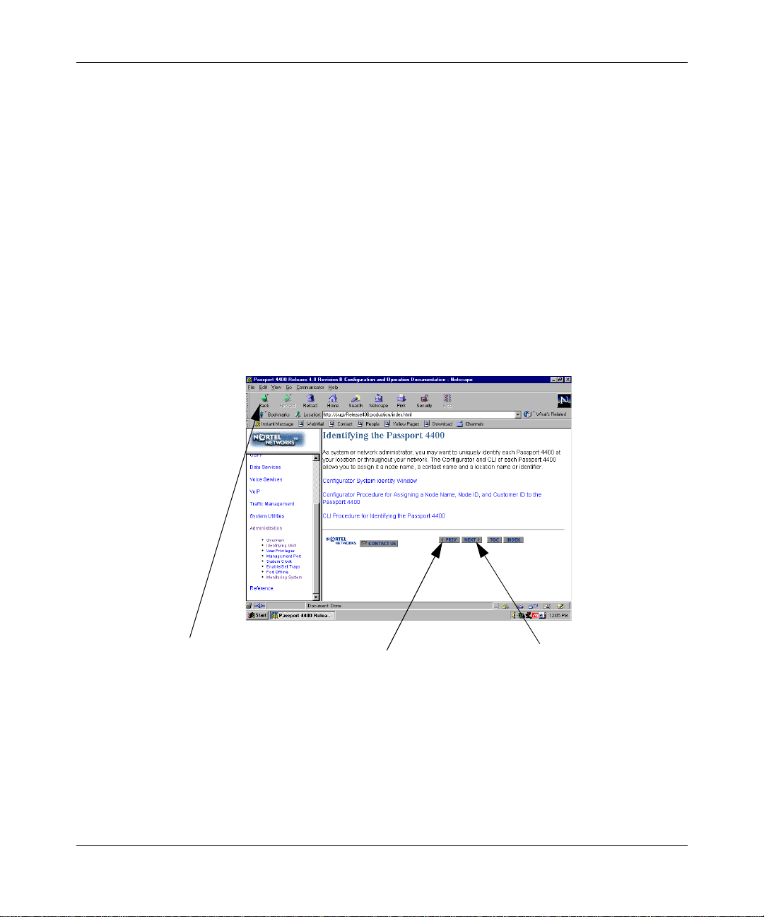
Navigating Online Documentation
The next and previous buttons in the document pages navigate you through the
pages sequentially. If, for example, you have jumped (hyperli nked) to a new page
and wish to return to your previous location, use the back button in the browser.
Chapter 2 Online Documentation
21
Back. Return s y ou to th e
previous display. This is good
for jumping between
procedures or returning to the
previous screen after a
hyperlink jump.
PREV. This takes you to the
previous page in the document
regardless of how you got to
this page. Do not confuse this
PREV with Back.
NEXT. This takes you to the
next page in the document
regardless of how you got to
this page.
Getting Started with Passport 4400, Release 4.1
Page 22
22
Chapter 2 O nli ne Docume ntation
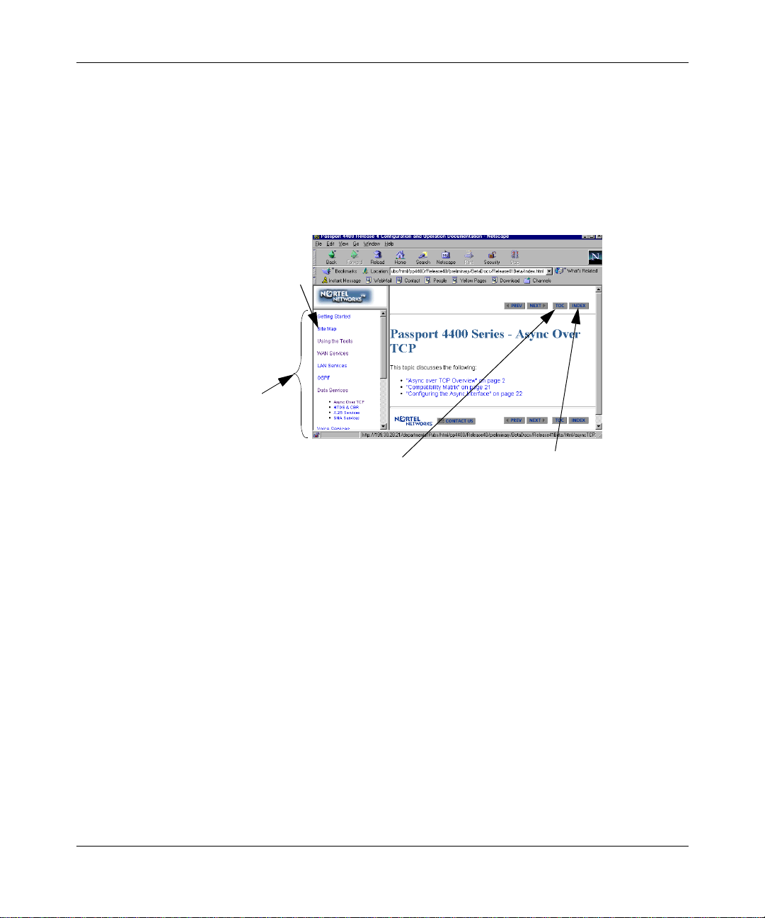
There are four navigation tools to help you locate the information you require:
• the navigation menu in the left window.
• the table of contents, accessible from the TOC button on each page.
• the index, accessible from the index button on each page.
• the site map in the right window (accessed from the navigation tree). This is
shown on page 23.
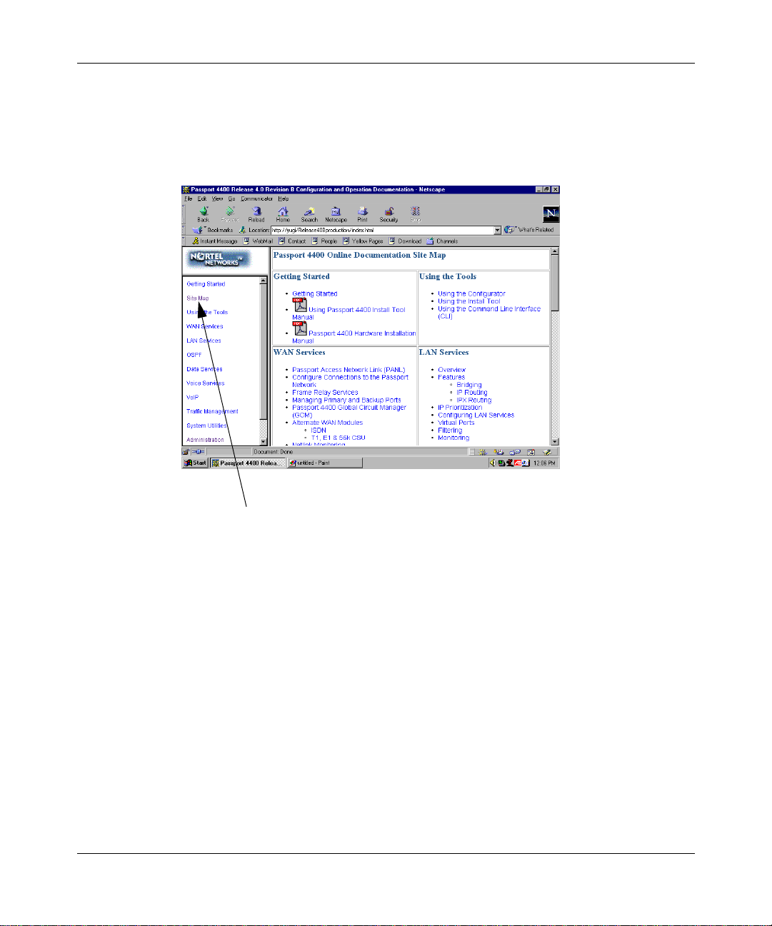
Site Map
See illustration
which follows
Navigation Tree
Click on a major
topic and sub
topic will display
TOC: Table of Contents
This will take you to a
comprehensive T able of
Contents (many pages).
It is not the preferred method.
Note that the Table of Contents
does not match either the
Navigation Tree or the Site Map.
It is merely a different method of
navigation.
INDEX
This will take
you to the index
209664-A
Page 23
Chapter 2 Online Documentation
Site Map
The site map is an expanded version of the Navigation Tree. It permits you to
browse through the documents to select the items you wish to view.
23
From any place in the documentation,
select Site Map from the Navigation Tree
to display the Site Map
Getting Started with Passport 4400, Release 4.1
Page 24

24
Chapter 2 O nli ne Docume ntation
Within the documentation, there are two additional aids to help you: the end of
topic sign and the end of procedure sign. When you see these aids, you have
reached the end of the logical discussion. By pressing next you will be moved to
new topic which may be completely unrelated.
209664-A
This is the end of this topic. By pressing the
next button, you may or may not be at the
next logical topic.
This lets you know that this
procedure is now complete
Page 25

Printing Online Documentation
In some cases, the HTML pages will not prin t proper ly. For print purposes, a copy
of the documentation in PDF form is provide d (config_ops _doc.pdf). Use th e PDF
file for printing requirements. It is recommended that you use a PostScript printer
driver.
Browsers
The Configuring and Operation Passport 4400 Rel. 4 Software has been tested
with the following browsers:
• Microsoft Internet Explorer 3, 4, and 5
• Netscape Communicator 4.5, 4.6, and 4.7
• Netscape Navigator 3 and 4
• Opera 3.60
• Mosaic 3
Chapter 2 Online Documentation
25
The Online Documentation has been tested with the following operating systems:
• Microsoft Windows 95
• Microsoft Windows NT 4, Workstation and Server
Best results are obtaine d when using a combinatio n of Microsoft Inte rnet Explorer
4 and 5 on a Pentium PC running Microsoft Windows 95 or NT, having a display
of 800 by 600 minimum resolution and capable of displaying 32,000 colors or
more.
Getting Started with Passport 4400, Release 4.1
Page 26

26
Chapter 2 O nli ne Docume ntation
Use the following tabl e to g et the opti mum res ults from the browse r you ar e u sing.
Browser How to Get Optimum Results
Microsoft Internet Explorer 4 or 5 Normal browser setup will provide optimum results.
Microsoft Internet Explorer 3 For best results, you should set the browser to
Netscape Communicator 4.5,
4.6, 4.7
Netscape Navigator 4.08 As a minimum, you should make sure the browser
Netscape Navigator 3 Normal browser setup will provide optimum results.
disable using style sheets:
1. Select View -> Options and select the Advanced
tab.
2. Uncheck the box next to Use style sheets.
3. Click on the Apply button.
Also, you should choose the No Frames option from
the online document ation startup page. The fr ameset
for the online documentation may not be stable in
Microsoft Internet Explorer 3. You may encounter
pages displayed outside of the frameset.
As a minimum, you should make sure the browser
window size is at leas t 800 b y 600 pixel s. If yo u mus t
run the browser in a smaller window size or you
encounter display problems, you should set the
browser to Disable using styles sheets:
1. Select Edit - > Preference s and select Advanced.
2. Uncheck the b ox next to Enable style sheets.
3. Click on the OK button.
However, Navigator 3 does not support cascading
style sheets, so the browser's d efa ult fonts are us ed.
Navigator 3 uses serif fonts, black on a white
background, as the default display.
209664-A
Page 27

Chapter 2 Online Documentation
Browser How to Get Optimum Results
Opera 3.60 Normal browser setup will provide optimum results.
Mosaic 3 Normal browser setup will provide optimum results.
However, Mosaic 3 does not support frames or
cascading style sheets. The browser's default font
set is used. Also, when you access the
and Operation Passport 4400 Rel. 4 Software,
206916-A
the browser does not support frames. Just click on
the link provided to use the documentation without
the frameset.
with Mosaic 3, you will see a message that
Configuring
27
Getting Started with Passport 4400, Release 4.1
Page 28

28
Chapter 2 O nli ne Docume ntation
209664-A
Page 29

Chapter 3
Hardware Setup
This chapter contains information for the required hardware needed to set up a
workstation and a Passp ort 4460. These req uirements will vary in accordan ce with
the navigation tool you are using.
Workstation Requirements
Following is a list of workstation requirements needed for the Device and
Network Management Tools.
If you are using.... Y ou need ....
29
Install Tool Windows-based PC (see chart on page 15)
Passport 4400 Configurator Any workstation that supports either Internet Explorer
4.0 or Netscape Communic ator 4.5 browser (see ch art
on page 15)
Command Line Interface (CLI) Dumb terminal or terminal emulation software (see
chart on page 15)
Mass Deployment Reporting
Tool (MDT)
Optivity NMS 9.0 Any workstation (see chart on page 17)
Preside Multiservice Data
Manager (PMDM)
Open Management System for
Passport (OMS-P)
Windows-based PC (see chart on page 15)
Any workstation (see chart on page 17)
Any workstation (see chart on page 17)
Getting Started with Passport 4400, Release 4.1
Page 30

30
Chapter 3 Hardware Setup
Installing Passport 4460 Hardware
The next four steps must be executed before you can operate your Passport 4460
unit.
Installation information can be found in the Reference for Passport 4460
Hardware, (205677-A).
Install the Flash card, C hapter 4
1
Attach the interface cables, Chapter 6 (also refe r to Reference for Passport
2
4400 Cables, 205678-A)
Connect the workstation, Chapter 7
3
Power up your Passport 4460 unit, Chapter 1
4
In Chapter 1 of this manual, you were asked to evaluate the device management
tools you are going to use. Refer to the table below and then go to the next
procedure.
209664-A
If you are using.... Refer to....
Passport 4400 Configurator Chapter 4 of this manual
Command Line Interface (CLI) Chapters 5 and 6 of this manual
Install Tool Using Passport 4400 Install Tool Version
4.1, 206906-B
Mass Deployment and Reporting Tool Using the Pas sport 44 00 Ma ss Depl oyme nt
and Reporting Tool, 209665-A
If you are using any of the network mana gement too ls, ref er page 16 and page 17.
Also note that the Configuring and Operation Passport 4400 Rel. 4 Software will
be a good source of product and parameter information as you configure your
unit.
Page 31

Chapter 4
Configurator Procedure for Creating a Node
Profile
A node profile is require d for links est ablished bet ween the Passpo rt 4460 unit and
the Passport network. This chapter explains the node profile configuration
procedure using Passport 4400 Configurator as your device management tool:
• “Accessing the Configurator Through a Web Browser” on page 32
• “Viewing Node Profile Information” on page 33
• “Defining a Unique DNA Prefix” on page 34
• “Defining a Node Name” on page 35
• “Defining a Node ID” on page 36
• “Defining a Customer ID” on page 37
• “Resetting the Unit” on page 37
• “Setting the DNA Numbering Plan” on page 38
• “Passport 4400 Configurator Documentation URL Update” on page 39
• “Setting the System C lock” on page 40
• “A confirmation message “Command Successful” indicates you have
successfully updated the System Clock on your Passport 4460 unit.” on
page 41
31
You need a properly configured workstation to use Configurator to access a
Passport 4460. Refer to Using Passport 4400 Install Tool Ve rsion 4.1, 206906-A,
Chapter 5, Configuring the Workstation, for a detailed description of the
requirements and procedures for setting up the workstation.
Note:
null modem is not required for the ethernet connection.
The null modem driver is required for a direct connection. The
Getting Started with Passport 4400, Release 4.1
Page 32

32
Chapter 4 Configurator Procedure for Creating a Node Profile
Accessing the Configurator Through a Web Browser
To access Configurator:
Note:
browser on a Sun Sparc workstation, you may encounter the following
error message: "URL could not be retrieved." Try deleting the Netscape
directory in your home directory. This will force Netscape to re-initialize
itself. Before deleting the directory, remember to copy all of your prior
settings and bookmarks into another directory.
Start your web browser and enter the IP address for your Configurator web
1
pages (http://192.168.200.200). The Username and Password dialog box
opens.
Enter the default User Name (passport) and Password (private).
2
Click OK. The Configurator Main window opens:
3
When first accessing Configurator through the Netscape web
209664-A
Page 33

Chapter 4 Configurator Procedure for Creating a Node Profile
The left side of the window displays the menu and the right side displays the
Passport 4400 unit’s main page. You are now logged into the Configurator
web pages.
Viewing Node Profile Information
To view your current node profile, use the following steps:
Click on Configure.
1
Click on System.
2
Click on Identity. The System Identity window opens:
3
33
Getting Started with Passport 4400, Release 4.1
Page 34

34
Chapter 4 Configurator Procedure for Creating a Node Profile
Defining a Unique DNA Prefix
To Define a unique DNA prefix:
Click on Configure.
1
Click on System.
2
Click on Identity. The System Identity window opens:
3
Enter the DNA prefix st ring for this Pa ssport 446 0 unit in the Devic e Network
4
Address field.
Note:
modifying your device network address. If you’d like to change your
DNA numbering plan go to “Overriding the DNA Numbering Plan” on
page 39.
Continue with “Defining a Node Name” on page 35.
Be careful not to delete the DNA numbering plan when
209664-A
Page 35

Chapter 4 Configurator Procedure for Creating a Node Profile
Defining a Node Name
T o def ine a nod e name, go to t he Syste m Identi fy window in the Node Name field
and enter the node name for this Passport 4460 (for example: pubsA).
If you don’t want to modify any more parameters in this window, click Save. A
“Command Successful” appears. If you are done, you must reset the system
before the new configuration takes effect. Go to “Resetting the Uni t” on page 37.
35
If your Passport 4460 is par t of a la r ger Pas sport network, yo u may want to de fine
a Node ID and Customer ID for network management purposes. Continue with
these steps:
• “Defining a Node ID” on page 36
• “Defining a Customer ID” on page 37
Getting Started with Passport 4400, Release 4.1
Page 36

36
Chapter 4 Configurator Procedure for Creating a Node Profile
Defining a Node ID
To define a Node ID, enter the node ID in the Node ID field. Enter an integer
between 1 and 65535 (for example, 23) . If your ne twork use s node ID s to iden tify
Passport 4400 units, be sure to assign each unit a unique node ID.
209664-A
If you don’t want to modify any more parameters in this window, click Save. A
“Command Successful” appears. If you are done, you must reset the system
before the new configuration takes effect. Go to “Resetting the Uni t” on page 37,
or continue with “Defining a Customer ID” on page 37.
Page 37

Chapter 4 Configurator Procedure for Creating a Node Profile
Defining a Customer ID
To Define a Customer ID:
Enter the customer ID in the Customer ID field. E nter an integer between 1
1
and 65535 (for example, 9265).
After you have completed modifying your parameters, click Save. A
2
Command Successful message appears.
37
You must reset the system before the new configuration takes effect.
3
Continue below.
Resetting the Unit
Click on Administration.
1
Click on System Reset. The System Reset window opens:
2
In the Reset Type field, use the pull down menu to select Configuration. Click
Reset. A unit reset confirmation message is displayed.
Getting Started with Passport 4400, Release 4.1
Page 38

38
Chapter 4 Configurator Procedure for Creating a Node Profile
Click OK. A display shows you the reset progress:
3
Setting the DNA Numbering Plan
To set the DNA numbering plan using Configurator, use the following steps:
Click on Configure.
1
Click on System.
2
Click on Identity. The System Identity window opens:
3
The DNA numbering plan is containe d in the f irst part of the Dev ice Netwo rk
Address.
If you’d like to change the DNA numbering pl an to e164 (if thi s is requir ed by
4
your Passport 6400), delete “[x121]”, and type “[e164]” before the DNA
prefix string. You will use x121 in Passport 4400 only networks.
Note:
appears after the DNA numbering plan.
Make sure that you don’t delete the DNA prefix string, which
209664-A
Page 39

Chapter 4 Configurator Procedure for Creating a Node Profile
After you have completed modifyi ng the DNA numberi ng plan, clic k Save. A
5
“Command Successful” message appears. This indicates you have
successfully updated the DNA numbering plan on your Passport 4460 unit.
Note:
Passport network, refer to Reference for Passport 4400 and 6400
Interworking, 209372-A
For more information concerning using a Passport 6400 in your
Overriding the DNA Numbering Plan
In addition to changing the DNA numbering plan, it is possible to override the
current numbering plan by entering the other numbering plan type within square
brackets [ ] in front of the DNA number.
To modify your DNA numbering plan, go to “Setting the DNA Numbering Plan”
on page 38.
Passport 4400 Configurator Documentation URL Update
39
When you have instal led th e onli ne docume ntati on on a web s ite, y ou must s et th e
documentation URL for the Passport 4400 Configurator in order to be able to
access the online documentation (Configuring and Operation Passport 4400 Rel.
4 Software, 206916-A) from within the Passport 4400 Configurator.
This URL can only be changed through the Passport 4400 Config ura tor web
pages.
Click on Administration.
1
Getting Started with Passport 4400, Release 4.1
Page 40

40
Chapter 4 Configurator Procedure for Creating a Node Profile
Click on Document URL. The Documentation URL window opens:
2
The URL in the window is where the online documentation is located, at the
Nortel Internet site, on your PC, workstation, server, or on the CD at your PC.
If you have downloaded the documentation elsewhere, enter the URL in the
3
Documentation Server URL field, and click Save. A “Command Successful”
appears.
Setting the System Clock
The Passport 4460 unit has an internal battery-backed calendar and clock. Upon
receiving a Passport 4460 unit from the factory, enter the current date and time:
To set the System Clock on your Passport 4460 unit, use the following steps:
From the table of contents menu, click on Administration.
1
209664-A
Page 41

Chapter 4 Configurator Procedure for Creating a Node Profile
Click on Date & Time. The Date and Time window opens:
2
Update any field you want to set, then click Save.
3
A confirmation message “Command Successful” indicates you have
4
successfully updated the System Clock on your Passport 4460 unit.
41
At this point you have completed the minimum requirements for getting started
using Configurator. Y our unit should no w be able t o communic ate on the network.
You will need to proceed with the configuration. Refer to Configuring and
Operation Passport 4400 Rel. 4 Software, 206916-A, (online documentation) to
continue.
Getting Started with Passport 4400, Release 4.1
Page 42

42
Chapter 4 Configurator Procedure for Creating a Node Profile
209664-A
Page 43

Chapter 5
Accessing the CLI and Basic Configuration
This chapter explains t he b asi c configuration procedure using the Command Line
Interface (CLI) as your device management tool. Proceed with the following:
• “Using a Terminal” on page 43
• “Communication Parameter Set-Up Requirements” on page 44
• “Logging into the CLI Using the Terminal Emulation Program” on page 46
• “Assigning the IP Address” on page 47
The Passport 4460 is shipped from the factory with a pre-configured IP address
(192.168.200.200). After you have accessed your Passport 4460 using this IP
address, you should assign an IP address specific to your Passport 4460 network
through the CLI.
43
Using a Terminal
Note:
program. The sample procedure below uses Wi ndows 95’s
HyperTerminal program.
Before you can access the CLI in your Passport 4460 unit, you must have
followed the physical installation procedures found in Reference for Passport
4460 Hardware, 205677-A, and powered-up the unit.
This procedure can be done using any terminal emulation
Getting Started with Passport 4400, Release 4.1
Page 44

44
Chapter 5 Accessing the CLI and Basic Configuration
Communication Parameter Set-Up Requirements
From the windows start menu, choose Program > Accessories >
1
HyperTerminal. You will see the HyperTerminal window.
Choose HyperTerminal. You will see the Connection Description window:
2
209664-A
Page 45

Chapter 5 Accessing the CLI and Basic Configuration
Enter a name to identify your Passport 4460 connection and Click OK. You
3
will see the Phone Number window:
Select the communication port to which you connected the Management Port
4
cable. Click OK. You will see the Port Settings window:
45
Getting Started with Passport 4400, Release 4.1
Page 46

46
Chapter 5 Accessing the CLI and Basic Configuration
Set the following communication par ameters for t he terminal:
5
Data Rate 9600 bps
Data Bits 8
Stop Bits 1
Parity None
Flow control Xon/Xoff
Note:
If you are unable to connect to the Passport 4460, try selecting
Hardware in the flow control field.
Click OK twice. You have now completed the Hyp erTerminal setup. Continue
6
on to Logging into the CLI Using the Terminal Emulation Program below.
Logging into the CLI Using the Terminal Emulation Program
Access the terminal emulation program you set up for this connection. A
1
blank window opens.
Press [Enter] until you see a
2
3
At the
prompt, type cli and press [Enter]. A
Login
displayed.
Press [Enter]. You are now logge d into the CLI and ready to initially
4
configure and assign an IP address to your Passport 4460 unit.
Continue on to Assigning the IP Address.
Login
prompt.
Password
prompt is
209664-A
Page 47

Chapter 5 Accessing the CLI and Basic Configuration
Assigning the IP Address
Passport 4460 uni ts are s hipped with a default IP addre ss of 1 92.168.200.200. You
need to change the IP address to match the configuration of your network.
To display the Passport 4460’s IfIndexes, type in the following command:
CLI> show ip address operational table
The following display is shown:
IfIndex : 1
IPAddress : 199.30.20.77
Mtu : 1500
DataLinkType : ether
KeepAlive : on
ForwardBcast : off
IPNumber : numbered
RouteProtocolType : disable
47
IfIndex : 2
IPAddress : 199.168.25.24
Mtu : 1500
DataLinkType : fr
KeepAlive : off
ForwardBcast : off
IPNumber : numbered
RouteProtocolType : rip
IfIndex : 32
IPAddress : 199.168.200.200
Mtu : 1500
Note:
are named exp1, exp2; the PCMCIA module is named pcmciaExp.
The name for the base module is always base; Expansion modules
Getting Started with Passport 4400, Release 4.1
Page 48

48
Chapter 5 Accessing the CLI and Basic Configuration
Use the following CLI command to assign the IP address:
5
CLI> add ip address entry
Parameter Range of Values Required Actions
<IfIndex> INTEGER (1..255) Enter the IfIndex of the Interface
<IPAddress> IPAddress Enter the IP address you want to
<NetMask> Sub-NetMask
<BcastAddress> IPAddress The IP address used for broadcasting.
(255.255.255.0,
255.255.0.0, or
255.0.0.0)
Example:
CLI> add ip address entry 3 192.168.22.22 255.255.0.0 192.168.255.255
displayed in Step .
assign the Passport 4460.
Enter the subnet mask. The bits of the
subnet mask are set to 1 if the
Passport 4460 should treat the
corresponding bit in the IP address as
part of the IP network prefix.
209664-A
Save the configuration and reset the unit.
6
CLI> save configuration update
CLI> reset system current reset
Page 49

Chapter 6
CLI Procedure for Creating a Node Profile
A node profile is required fo r links establ ished be twee n the Passp ort 4460 an d the
Passport network.
This chapter explains the node profile procedure using CLI as your device
management tool:
• “Viewing Node Profile Information” on page 50
• “Defining a Unique DNA Prefix” on page 51
• “Defining a Node Name” on page 52
• “Defining Node ID” on page 53
• “Defining Customer ID” on page 53
• “Confirming the New Configuration” on page 54
• “Saving the Current Configuration and Resetting the Unit” on page 54
• “Setting the System C lock” on page 55
49
Getting Started with Passport 4400, Release 4.1
Page 50

50
Chapter 6 CLI Procedure for Creating a Node Profile
Viewing Node Profile Information
To view your current node profile, use the following CLI commands:
CLI> show msm profile
A table similar to the foll owing is displayed:
NodeID 1 (operational)
23 (configured)
Customer ID 0 (operational)
9265 (configured)
DNAPrefix “[x121]” (operational)
“[x121]123456789012” (configured)
CLI> show system admin istration
A table similar to the foll owing appears:
ConfigVersion :"Passport_4430/50_Appl_Rel4.0.0_Rev”
ObjectID “1.3.6.1.4.1.335.1.4”
UpTime 00Years 001Days 23:49:26
Contact “ “
NodeName “PUBSA”
Location “ “
Services 4
209664-A
Page 51

Chapter 6 CLI Procedure for Creating a Node Profile
Defining a Unique DNA Prefix
To define a unique DNA prefix, use the following CLI command:
CLI> define msm profile dnaPrefix
Parameter Range of Values Required Action
<DNAPrefix> “String” (1..31) Enter the DNA prefix string for this
Example:
CLI> define msm profile dnaPrefix “626555134201”
Note:
of numbering plan. If you want to override the default numbering plan,
see Configuring and Operating Passport 4400 Rel. 4 Software,
206916-A.
When entering the DNA prefi x, it is not n ece ssary to enter the type
Passport 4460 unit. The string
enclosed within quotation marks.
must
51
be
Continue with “Defining a Node Name” on page 52.
Getting Started with Passport 4400, Release 4.1
Page 52

52
Chapter 6 CLI Procedure for Creating a Node Profile
Defining a Node Name
To define a node name, use the following CLI command:
CLI> set system administration NodeName
Parameter Range of Values Required Action
<NodeName> “String” (1..50) Enter the node name to be assigned to
Example:
CLI> set system administration NodeName “456543”
If you don’t want to modify any more parameters in this window, you must save
and reset the system before the new configuration takes effect. Go to “Saving the
Current Configuration and Resetting the Unit” on page 54.
this Passport 4460 unit. The string
be enclosed within quotation marks.
must
209664-A
If your Passport 4460 is par t of a la r ger Pas sport network, yo u may want to de fine
a Node ID and Customer ID for network management purposes. Continue with
these steps:
• “Defining Node ID” on page 53
• “Defining Customer ID” on page 53
Page 53

Defining Node ID
To define a node ID, use the following CLI command:
CLI> define msm profile nodeID
Parameter Range of Value Required Action
<NodeID> INTEGER (1..65535) Enter an integer between 1 and
Example:
CLI> define msm profile nodeID 23
If you don’t want to modify any more parameters in this window, go to “Saving
the Current Configuration and Resetting the Unit” on page 54, or continue with
“Defining Customer ID” on page 53.
Chapter 6 CLI Procedure for Creating a Node Profile
65535. If your network uses node
IDs to identify Passport 4460 units,
be sure to assign each uni t a uniqu e
node ID.
53
Defining Customer ID
To define a customer ID, use the following CLI command:
CLI> define msm profile customerID
Note:
customer ID is expressed as an integer between 0 and 65535. The terms
MPANL and PANL both refer to the same protocol and may be used
interchangeably.
Parameter Range of Value Required Action
<CustomerID> INTEGER (0..65535) Enter an integer between 1 and
The element msm signifies the MPANL signal mechanism. The
65535.
Getting Started with Passport 4400, Release 4.1
Page 54

54
Chapter 6 CLI Procedure for Creating a Node Profile
Example:
CLI> define msm profile customerID 9265
Confirming the New Configuration
To confirm your new configuration, use the following CLI command line:
CLI> show msm profile
A table similar to the foll owing is displayed:
NodeID 1 (operational)
23 (configured)
Customer ID 0 (operational)
9265 (configured)
DNAPrefix “[x121]” (operational)
“[x121]123456789012” (configur ed)
Any changes that have been made to the node ID, customer ID, and DNA prefix
will show up as configured in the display above.
Saving the Current Configuration and Resetting the Unit
To save and reset the unit, use the following CLI command line:
CLI> save configuration update
CLI> reset system current reset
After saving the curr ent configura tion and resetti ng the Passport 4460 unit, use the
CLI command,
Customer ID, and DNAPrefix parameters should display as operational and
configured.
209664-A
show msm profile
to view your changes. The NodeID,
Page 55

Chapter 6 CLI Procedure for Creating a Node Profile
Setting the System Clock
The Passport 4460 unit has an internal battery-backed calendar and clock. Upon
receiving a Passport 4460 unit from the factory, enter the current date and time:
CLI> set system timeOfDay
The following list is displayed:
date
day
hour
minute
month
second
year
Enter each element you wish to set.
Example:
55
CLI> set system timeOfD ay date
.
Parameter Range of Value Required Action
<Date> INTEGER (1..31) Enter an integer between 1 and 31.
If it is a single digit month you must
add a zero in front of it. The year
must include 4 digits.
Example:
CLI> set system timeOfD ay date 9
To view the settings, use the show system time of Day.
Example:
CLI> show system timeOfDay
Getting Started with Passport 4400, Release 4.1
Page 56

56
Chapter 6 CLI Procedure for Creating a Node Profile
Information similar to the following is displayed:
04/09/2000 18:30:15 Monday
209664-A
Page 57

Appendix A
IfIndexes and Interface Identification
The following topics are discussed in this chapter.
•“IfIndex Overview” on page 57
•“Hard-Coded IfIndexes” on page 58
•“Reserved IfIndexes and Ranges” on page 58
•“IfIndex Table Display Definitions” on page 62
IfIndex Overview
Each physical and virtual interface on the Passport 4460 is assigned an IfIndex, a
unique identifier that allows SNMP to read and write status information. These
IfIndexes are used to establish logical links between interfaces and higher-level
applications and protocol stacks.
57
The Passport 4460 can suppo rt up to 25 5 IfInd exes. Some of these a re hard- coded
and cannot be changed; others are automatically reserved by the Passport 4460
operating system when the unit is powered on.
For more information on IfIndexes, proceed to the the following:
•“Hard-Coded IfIndexes” on page 58
•“Reserved IfIndexes and Ranges” on page 58
•“IfIndex Table Display Description” on page 60
Getting Started with Passport 4400, Release 4.1
Page 58

58
Appendix A IfIndexes and Interface Identification
Hard-Coded IfIndexes
The following IfIndex numbers are hard-coded, representing the interfaces that
are initially present in the Passport 4460.
IfIndex Description
1 Logical Ethernet interface for routed LAN traffic
2 Virtual port for WAN traffic
3 Logical Ethernet interface for bridged LAN traffic
4 Virtual port for network management traffic
Reserved IfIndexes and Ranges
The Passport 4460 also reserves IfIndexes for available ports on the base module
and expansion data modules. By reserving these IfIndexes, the Passport 4460
guarantees that a specific port always uses the same IfIndex. For instance, Port 1
always uses IfIndex 150 to refer to the physical interface.
209664-A
The following table lists I fIndexes that are r eserved f or use by t he ports l ocated on
the base module.
Port Number IfIndex - Physical Port IfIndex - Connector IfIndex - Service
1 150 151 152
2 153 154 155
3 156 157 158
There are three reserved IfIndexes associated with each port. For Port 1, IfIndex
150 refers to the phys ic al port interface, 151 re fers to the connector interface, and
152 refers to the frame relay service.
Page 59

Appendix A IfIndexes and Interface Identification
IfIndex Ranges
Although the following ranges of IfIndexes may not currently be assigned, they
are reserved and you should assign them only to the indicated interface type:
• 1-4: Ethernet port assignments
• 5-32: Additional virtual ports
• 33-148: Voice assignments
• 149-206: WAN port and Expansion port assignments
Note:
dex assignment for the primary netlink is 149 or 147 (for units with only
one Ethernet Base Module port ava ilable) . The Pass port 440 0 Ins tall Tool
automatically deletes IfIndex assignments 149 and 147. Install Tool may
be used at any time for installation and/or configuration of the Passport
4460 unit. You should make sure the primary netlink is assigned to an
IfIndex of 207 or higher, and avoid assigning anything to either IfIndex
149 or 147.
If the Passport 4460 unit is set to factory defaults, the default IfIn-
59
Safe IfIndex Ranges
You can assign available IfIndexes between 207 and 255 when creating, for
example, a frame relay tunnel PVC, and not worry about the assignment being
overwritten when new modules are defined on the Passport 4460 unit. Go to,
•“IfIndex Overview” on page 57
•“Hard-Coded IfIndexes” on page 58
•“IfIndex Table Display Description” on page 60
Getting Started with Passport 4400, Release 4.1
Page 60

60
Appendix A IfIndexes and Interface Identification
IfIndex Table Display Description
You can display a list of all IfIndexes currently assigned to interfaces on the
Passport 4460. Go to:
•“Configurator Procedure for Displaying the IfIndex Table” on page 60
•“CLI Procedure for Displaying the IfIndex Table” on page 61
•“IfIndex Overview” on page 57
•“Hard-Coded IfIndexes” on page 58
•“Reserved IfIndexes and Ranges” on page 58
Configurator Procedure for Displaying the IfIndex Table
To display IfIndexes through Configurator:
Click on Status/Statistics.
1
Click on All Interfaces. You will see the Interface Status/Statistics window.
2
Below is a partial display of the IfIndex Table using Configurator.
209664-A
See “IfIndex Table Display Definitions” on page 62 for a description of the
3
above parameters.
Page 61

Appendix A IfIndexes and Interface Identification
CLI Procedure for Displaying the IfIndex Table
The following sample display is taken from a Passport 4460 with two expansion
modules installed, an ISDN BRI S/T Voice module and a T1 Voice module. Belo w
is a partial display of the IfIndex Table using CLI.
CLI> show system IfIndex Operational
IfIndex IfExtType PPA Slot
1 ethernetCsmacd 0 base
2 propVirtual 0 base
3other 0base
4 propVirtual 1 base
5isdns 1exp1
6ds0 1exp1
7ds1 0exp2
8other 0exp2
9other 0exp2
10 other 0 exp2
11 other 0 exp2
12 other 0 exp2
13 other 0 exp2
14 other 0 exp2
15 other 0 exp2
16 other 0 exp2
61
Getting Started with Passport 4400, Release 4.1
Page 62

62
Appendix A IfIndexes and Interface Identification
IfIndex Table Display Definitions
Interface Extension Type
The interface extension type, shown as IfExtType in the display above, describes
the port, protocol, service, or other interface identified by the IfIndex. The
following table describes some of the common interface extension types seen on
the Passport 4460.
ethernetCsmacd The Ethernet port (10BASE-T or AUI) on the base module. This
propVirtual A virtual port on the Pass port 446 0. Virtual ports a re u se d to di rec t
propMultiplexor A physical port on the Passport 4460. There are three physical
frameRelay A frame relay protocol implemented on a physical port.
frameRelayService A frame relay protocol implemented on a physical port.
v35 The connector type for a physical port. V.35 is one of several
other The protocol or service for this IfIndex is undefined or unknown to
interface is always assigned IfIndex 1.
traffic across a WAN link. By default, there are two virtual ports,
assigned IfIndexes 2 and 4. For more information on virtual ports,
see the Online Documentation,
ports on the base module.
frameRelay
RFC1490 netlinks.
frameRelayService
connector types supported on Passport 4460 physical ports. For
more information, refer to
205678-A or
205677-A
the Passport 4460.
refers to the switching protocol used for PANL and
refers to Frame Relay DCE service.
Reference for the Passport 4460 Hardware
.
LAN Services
Reference for the Pas sport 4400 Cables ,
.
,
PPA Number
The Point of Physical Attachment (PPA) is not a literal physical point of
attachment, but is an internal identifier for the Passport 4460 code. Each PPA can
have one or more IfIndexes associated with it, but the PPA numbers are unique
only within the module; they are not unique across all devices or slots.
209664-A
Page 63

Appendix A IfIndexes and Interface Identification
63
For physical interfaces, the PPA number corresponds to the physical port number
on the module. For logical or virtual interfaces, the number corresponds to a
logical port or inter face a nd is depe ndent on the int erfac e module t ype. If a de vice
does not support PPAs, the value -1 indicates that the field is not used as an
identifier.
Slot Name
The physical interf ace module is the na me that the Passpor t 4460 uses to ident ify a
module interface. The base module is always base, and expansion modules are
named exp1 and exp2.The Serial Daughter Boards (SDBs) are considered
expansions to t he bas e mo dule itsel f, an d a re r eferr ed t o as Port 2 a nd Port 3 of the
base module.
Channel Number
The channel number along with the slot and PPA number, uniquely identifies an
interface within a device type. However, the channel number itself is not unique
across all device types.
To display the channel number of an interface, along with additional interface
information, use the following CLI command:
CLI> show system interfaceExtension operational table
See “Configurat or Proce dure fo r Displ aying t he IfInde x Table” on page 60 for the
Configurator steps for displaying IfIndex parameters.
For interfaces describing serial data connections (data ports), the channel number
refers to the physical data channel. For interfaces describing voice channels, the
channel number refers to the corresponding voice channel number. For interface
types that do not use a channel number, the value of -1 is used.
Getting Started with Passport 4400, Release 4.1
Page 64

64
Appendix A IfIndexes and Interface Identification
209664-A
Page 65

Appendix B
Installing System Software from the CD-ROM
For software installation for Install Tool, refer to Using Passport 4400 Install Tool
Version 4.1, 206906-B.
For software installation for the Mass Deployment and Reporting Tool, refer to
Using the Passport 4400 Mass Deployment and Reporting Tool, 209665-A
For software installa tion for the syst em sof tware from the CD-ROM, f ollow the se
steps:
Place the CD into the drive
1
From the D: drive (where D: is your CD-ROM drive) icon on your screen
2
double click on the CD icon
Double click on software
3
65
Application Code
The application code is installed on your Passport 4460 unit as you download the
application software.
The Passport 4460 application software is a sing le f il e ( pr41 xxxx.bld) supplied in
a “bld” format consisting of the following executable images:
• Ethernet Base Module code (PR4_1_0.CMP and IO4_1_0.CMP)
• DSP code for voice (dspc54xx.voc)
• Code for the Passport 4400 Configurator (HTML.CMP)
Getting Started with Passport 4400, Release 4.1
Page 66

66
Appendix B Installing System Software from the CD-ROM
Downloading Application Software
The following procedures are contained in this section:
• “Configurator Procedure for Downloading Application Software” on page 66
• “CLI Procedure for Downloading Application Software” on page 69
Configurator Procedure for Downloading Application Software
The following tasks must be completed:
• “Enter the IP address of the TFTP Host Workstation and Download the Code
Files” on page 66
• “Commit the Application Code Bank” on page 67
• “Save the Current Configuration and Reset the Unit” on page 68
Enter the IP address of the TFTP Host Workstation and
Download the Code Files
Under Administration, select TFTP Operation. You will see the TFTP
1
Operation window:
In the Server IP Address field, enter the IP address of the TFTP host
2
workstation where the download code files reside.
Click Save. A “Command Successful” appears.
3
209664-A
Page 67

Appendix B Installing System Software from the CD-ROM
At the top of the window, click on Code Download. You will see the TFTP
4
Code Download window:
In the Filename field, enter the filename and path (if applicabl e).
5
Click Download (from Server). A Command Successful message appears.
6
To verify the downloa d st at us, c li ck on TFTP Status at the top of t he wi ndow.
7
You will see the TFTP Status w indow:
67
This window displays the progress of the download process.
Take note of the Transfer Mode status (To_Bank_1 or To_Bank_2). You will
8
need this value to continue with the next procedure.
When the Last Transfer Status shows Download Successful, you r download is
9
complete.
Commit the Application Code Bank
Select Administration and Code Bank.
1
Getting Started with Passport 4400, Release 4.1
Page 68

68
Appendix B Installing System Software from the CD-ROM
You will see the Code Bank window:
Next to Commit Bank, use the pull down menu and select the code bank that
2
was displayed in step 8 of the previous procedure.
The opposite bank is now uncommitted, and a subsequent application code
download will write to that bank.
Click Save. A “Command Successful” appears.
3
209664-A
Save the Current Configuration and Reset the Unit
Under Administration select System Res et. You will see the System Reset
1
window.
In the Reset Type field, use the pull down menu to select Configuration. Click
2
Reset. A unit reset confirmation message is displayed:
Click OK. A display shows you the reset progress
3
Page 69

Appendix B Installing System Software from the CD-ROM
CLI Procedure for Downloading Application Software
Load the Passport 4460 Releas e 4.1 soft ware onto yo ur TFTP server (boot and
1
application code as required).
Access the CLI (it may be necessary to do this through a Telnet session).
2
Download the boot code (if necessary). Otherwise, skip this step.
3
Example:
Download base image specific 192.168.15.30 “bt41xxxx.bld”. This will
download the file bt41xxxx.bld from the TFTP host with the IP address
192.168.15.30 (where x’s represent the current version/filename).
Download the Release 4.1 applica ti on cod e onto the Passport 4460 unit using
4
TFTP.
Commit the application code bank that will be write-protected during the
a
download
Example:
69
CLI> set system firmwa re commitcodebank bank 1
This will write-prot ect ap plica tion c ode bank 1 . The appl icati on code wil l
be downloaded into bank 2.
Download the application code,
b
Example:
CLI> download base image specific 192.168.15.30 “pr41xxxx.bld”
This command downloads the file pr41xxxx.bld from the TFTP host
whose IP address is 192.168.15.30 (where x’s represent the current
version/filename).
Commit the new application softwa re to the write-protect ed bank.
5
Example:
CLI> set system firmwa re commitcodebank bank2
Getting Started with Passport 4400, Release 4.1
Page 70

70
Appendix B Installing System Software from the CD-ROM
Restart the Passport 4460 unit
6
Example:
CLI> reset system current reset
Log in to the CLI again. It may be necessary to establish another Telnet
7
session.
If you are upgrading your software, be sure to extract the latest MIBs and
8
install the new ones.
209664-A
Page 71

Index
71
A
accessing online documentation 19
Agencies
BABT 4
CSA 5
FCC 5
TUV 4
UL 4
assigning I P address 47
B
browsers 25
C
Canadian Requirements 5
Channel number 63
clock
setting 55
Command Line Interface (CLI)
assigning I P Address 47
confirming configuration 5 4
defining a node name 52
defining a unique DNA prefix 51
defining customer ID 53
defining node ID 53
description 14
logging in using terminal emulation 46
reset the unit 54
saving configuration 54
setting the system clock 55
viewing node profile 50
when to use it 15
workstation requirements 29
communication parameter set-up requirements 44
communication set-up 44
configuration
confirming 54
configurator
logging in 32
confirming
configuration 54
customer ID 53
defining 37, 53
D
defining
customer ID 37, 53
DNA prefix 34, 51
node ID 36, 53
node name 35, 52
DNA numbering plan
setting 38
DNA prefix
defining 34, 51
documentation
Chapter 2 19
downloading 19
navigating 20
open 20
URL update 39
Downloading application software
Configurator procedure 66
downloading documentation 19
downloading software
Getting Started with Passport 4400, Release 4.1
Page 72

72
Index
Appendix B 65
F
FCC Requirements 5
H
hard-coded
IfIndex 58
hardware
installation 30
I
IfIndex
hard-coded 58
interface extension type 62
overview 57
ranges 59
reserved 58
table display 60
table display definitions 62
IfIndex displays
definition 62
Install Tool 14
installing hardware 30
IP address
assigning 47
L
LIM 63
list of documentation 12
logging into configurator 32
logging into the CLI
terminal emulation 46
N
navigating online documentation 20
node ID 53
defining 36, 53
node name 52
defining 35, 52
node profile
creating
Chapter 5 49
Chapter 6 31
viewing 33, 50
O
online documentation
accessing 19
Chapter 2 19
installing 19
printing 25
Open Management System for Passport
(OMS-P) 16
open the documentation 20
Optivity NMS 9.0 16
P
Passport 4400 Configurator 14
Point of physical attachment 62
PPA number 62
Preside Multiservice Data Manager (PMDM) 16
printing online documentation 25
R
ranges 58
resetting the unit 54
M
management tools 14
Mass Deployment and Reporting Tool (MDT) 14
209664-A
S
Safety Information 4
saving
Page 73

configuration 54
setting
DNA numbering plan 38
system clock 40
setting the system clock 55
set-up requirements
communication parameter 44
system clock
setting 40
U
Unique DNA prefix 51
unpacking the unit 12
URL 39
Using Configurator
through a web browser 32
V
Index
73
viewing
node profile 33, 50
W
Warnings 4
workstation requirements 29
Getting Started with Passport 4400, Release 4.1
Page 74

74
Index
209664-A
 Loading...