

Page 1

Nautica Wizard
Installation Guide
Part No. 302269-A Rev.00
April 1998
Page 2

4401 Great America Parkway 8 Federal Street
Santa Clara, CA 95054 Billerica, MA 01821
Copyright © 1998 Bay Networks, Inc.
All rights reserved. Printed in the USA. April 1998.
The information in this document is subject to change without notice. The statements,
configurations, technical data, and recommendations in this document are believed to be
accurate and reliable, but are presented without express or implied warranty. Users must
take full responsibility for their applications of any products specified in this document.
The information in this document is proprietary to Bay Networks, Inc.
The software described in this document is furnished under a license agreement and may
only be used in accordance with the terms of that license. A summary of the Software
License is included in this document.
Trademarks
Nautica and Bay Networks are registered trademarks and BCC, Nautica Wizard, and the
Bay Networks logo are trademarks of Bay Networks, Inc.
Microsoft, MS, MS-DOS, Win32, Windows, and Windows NT are registered trademarks
of Microsoft Corporation.
All other trademarks and registered trademarks are the pr operty of their respective owners.
Restricted Rights Legend
Use, duplication, or disclosu re by the United States Gov ernment is sub ject to restrictio ns as
set forth in subparagraph (c)(1)(ii) of the Rights in Technical Data and Computer Software
clause at DFARS 252.227-7013.
Notwithstanding any other license agreement that may pertain to, or accompany the
delivery of, this computer software, the rights of the United States Government regarding
its use, reproduction, and disclosure are as set forth in the Commercial Computer
Software-Restricted Rights clause at FAR 52.227-19.
Statement of Conditions
In the interest of improving internal design, operational function, and/or reliability, Bay
Networks, Inc. reserves the right to make changes to the products described in this
document without notice.
Bay Networks, Inc. does no t assume an y liabilit y t hat may oc c ur due to the use or
application of the product(s) or ci rcuit layout(s) described herein.
Portions of the code in this so ftware product are Co pyright © 1988, Regents of the
University of California. Al l rights reserved. Redist ribution and use in source and binary
forms of such po rtions are permitted, provided that the above copyright noti ce and this
paragraph are duplic ated in all such forms and that any documentation, advertising
materials, and other materials related to such distribution and use acknowledge that such
portions of the software were developed by the University of California, Berkeley. The
name of the University may not be used to endorse or promote products derived from such
portions of the software witho ut speci fic prior written permission.
ii 302269-A Rev.00
Page 3

SUCH PORTIONS OF THE SOFTWARE ARE PROVIDED “AS IS” AND WITHOUT
ANY EXPRESS OR IMPLIED WARRANTIES, INCLUDING, WITHOUT
LIMITATION, THE IMPLIED WARRANTIES OF MERCHANTABILITY AND
FITNESS FOR A PAR TICULAR PURPOSE.
In addition, the program and information contained herein are licensed only pursuant to a
license agreement that contains restrictions on use and disclosure (that may incorporate by
reference ce rtain limitations and notices imposed by third parties).
Bay Netw orks, Inc. Software License Agreement
NOTICE: Please carefully read this license agreement before copying or using the
accompanying software or installing the hardware unit with pre-enabled software (each of
which is referred to as “Software” in this Agreement). BY COPYING OR USING THE
SOFTWARE, YOU ACCEPT ALL OF THE TERMS AND CONDITIONS OF THIS
LICENSE AGREEMENT. THE TERMS EXPRESSED IN THIS AGREEMENT ARE
THE ONLY TERMS UNDER WHICH BAY NETWORKS WILL PERMIT YOU TO
USE THE SOFTWARE. If you do not accept these terms and conditions, return the
product, unused and in the original shipping container, within 30 days of purchase to
obtain a credit for the full purchase price .
1. License Grant. Bay Networks, Inc. (“Bay Networks”) grants the end user of the
Software (“Licensee”) a personal, nonexclusive, nontransferable license: a) to use the
Software either on a single computer or, if applicable, on a single authorized device
identified by host ID, for which it was originally acquired; b) to copy the Software solely
for backup purposes in su pport of authorized use o f the Software; and c) to use and copy
the associated user manual solely in support of authorized use of the Software by Licensee.
This license applies to the Software only and does not extend to Bay Networks Agent
software or other Bay Networks software products. Bay Networks Agent software or other
Bay Netwo rks so ftw ar e pro duc ts a re licen sed f or u se unde r t he te rms of the a ppli cab le Ba y
Networks, Inc. Software License Agreement th at accompanies such software and upon
payment by the end user of the applicabl e license fees for such software.
2. Restrict i ons on us e ; r e se r vation of rights. The Software and user manuals are
protected under copyright laws. Bay Networks and/or its licensors retain all title and
ownership in both the Software and u ser manuals, incl uding any revisions made by Bay
Networks or its licensors. The copyright notice must be reproduced and inc luded with any
copy of any portion of the Software or user manuals. Licensee may not modify, translate,
decompile, disassemble, use for any competitive analysis, reverse engineer, distribute, or
create derivative works from the Software or user manuals or any copy, in whole or in part.
Except as expressly provided in this Agreement, Licensee may not copy or transfer the
Software or user manuals, in whole or in part. The Software and user manuals embody Bay
Networks’ and its licensors’ confidential and proprietary intellectual property. Licensee
shall not subl icense, assign, or otherwise disclose to any third party the Sof tware, or any
information about the oper atio n, de sig n, perfo rm anc e, or implem e ntatio n of the Softwa re
and user manuals that is confidential to Bay Networks and its licensors; however, Licensee
may grant permission to its consultants, subcontractors, and agents to use the Software at
Licensee’s facility, provided they have agreed to use the Software only in accordance with
the terms of this license.
302269-A Rev.00 iii
Page 4

3. Limited warranty. Bay Networks warrants each item of Software, as delivered by Bay
Networks and properly installed and operated on Bay Networks hard ware or other
equipment it is originally licensed for, to function substantially as described in its
accompanying user manual during its warranty per iod, which begins on t he date Software
is first shipped to Licensee. If any item of Software fails to so function during its warranty
period, as the so le re med y Bay Net wo r ks will a t it s d iscretio n p ro v id e a su ita ble fix, patch,
or workaround for the problem that may be included in a future Software release. Bay
Networks further warrants to Licensee that the media on which the Software is provided
will be free from defects in ma terials and w orkmanship un der normal us e for a period of 9 0
days from the date Software is first shipped to Licensee. Bay Networks will replace
defective media at no charge if it i s returned to Bay Networks during the warranty period
along with proof of the date of shipment. This warranty does not apply if the media has
been damaged as a result of accident, misuse, or abuse. The Licensee assumes all
responsibility for selection of the Software to achieve Licensee’s intended results and for
the installation, use, and results obtained from the Software. Bay Networks does not
warrant a) that the functions contained in the software will meet the Licensee’s
requirements, b) that the Software will operate in the hardware or software combinations
that the Licensee may select, c) that the operation of the Software will be uninterrupted or
error free, or d) that all defects in the operation of the Software will be corrected. Bay
Networks is not obl igated to remedy any Software defect that cannot be reproduced with
the latest Software release. These warranties do not apply to the Software if it has been (i)
altered, except by Bay Networks or in accordance with its instructions; (ii) used in
conjunction with another vendor’s product, resulting in the defect; or (iii) damaged by
improper environment, abuse, misuse, accident, or negligence. THE FOREGOING
WARRANTIES AND LIMITATIONS ARE EXCLUSIVE REMEDIES AND ARE IN
LIEU OF ALL OTHER WARRANTIES EXPRESS OR IMPLIED, INCLUDING
WITHOUT LIMITATION ANY WARRANTY OF MERCHANTABILITY OR FITNESS
FOR A PARTICULAR PURPOSE. Licensee is responsible for the security of it s own data
and information and for maintaining adequate procedures apart from the Software to
reconstr uct lost or altered files, data, or programs.
4. Limitation of liability. IN NO EVENT WILL BAY NETWORKS OR ITS
LICENSORS BE LIABLE FOR ANY COST OF SUBSTITUTE PROCUREMENT;
SPECIAL, INDIRECT, INCIDENTAL, OR CONSEQUENTIAL DAMAGES; OR ANY
DAMAGES RESULTING FROM INACCURATE OR LOST DATA OR LOS S OF USE
OR PROFITS ARISING OUT OF OR IN CONNECTION WITH THE PERFORMANCE
OF THE SOFTWARE, EVEN IF BAY NETWORKS HAS BEEN ADVISED OF THE
POSSIBILITY OF SUCH DAMAGES. IN NO EVENT SHALL THE LIABILITY OF
BAY NETWORKS RELATING TO THE SOFTWARE OR THIS AGREEMENT
EXCEED THE PRICE PAID TO BAY NETWORKS FOR THE SOFTWARE LICENSE.
5. Government Licensees. This provision ap pli es to all Sof tware and documentation
acquired directly or indirectly by or on behalf of the United States Government. The
Software and documentation are commercial products, licensed on the open market at
market prices, and were developed entirely at private expense and without the use of any
U.S. Government funds. The license to the U.S. Government is granted only with restricted
rights, an d use, duplication, or disclosure by the U.S. Government is subject to the
restrictions set forth in subparagraph (c)(1) of the Commercial Computer Software––
Restricted Rights clause of FAR 52.227-19 and the limitations set out in this license for
iv 302269-A Rev.00
Page 5

civilian agencies, and subparagraph (c)(1)(ii) of th e Rights in Technical Data and
Computer So ft ware clause of DFARS 252.227-7013, for agencies of the Department of
Defense or their successors, whichever is applicable.
6. Use of Software in the European Community. This provision applies to all Software
acquired for use within the European Community. If Licensee uses the Software within a
country in the European Community, the Software Directive enacted by the Council of
European Communit ies Dire cti v e dated 14 Ma y, 1991, will apply to th e e xamina tion of the
Software to facili ta te inte ro pera bil ity. Licensee agrees to no tify Bay Ne tworks of any such
intended examination of the Software and may procure support and assistance from Bay
Networks.
7. Term and termination. This license is effective until terminated; however, all of the
restrictions with respect to Bay Networks’ copyright in the Software and user manuals will
cease being effective at the date of exp iration of the Bay Networks copyright; those
restrictions relating to use and disclosure of Bay Networks’ confidential information shall
continue in effect. Licensee may terminate this license at any time. The license will
automatically termin ate if Licens ee fails to comply with any of the terms and condi tions of
the license. Upon termination for any reason, Licensee will immediately destroy or return
to Bay Networks the Software, user manuals, and all copies. Bay Networks is not liable to
Licensee for damages in any form solely by reason of the termination of this license.
8. Export and Re-export. Licensee agrees not to export, directly or indirectly, the
Software or related technical data or information without first obtaining any required
export lic ense s or ot her go vernmental appro v al s. Without limiting th e fo re goin g, L icens ee,
on behalf of itself and its subsidiaries and affiliates, agrees that it will not, without first
obtaining all export licenses and approvals required by the U.S. Go vernment: (i) export, reexport, transfer, or divert any such Software or technical data, or any direct product thereof,
to any country to which such exports or re-exports are restricted or embargoe d under
United States export control laws and regulations, or to any national or resident of such
restricted or embargoed countries; or (ii) provide the Software or related technical data or
information to any military end user or for any military end use, including the design,
development, or production of any chemical, nuclear, or biological weapons.
9. General. If any provision of this Agreement is held to be invalid or unenforceable by a
court of competent jurisdiction, the remainder of the provisions of this Agreement shall
remain in full force and effect. This Agreement will be governed by the laws of the state of
California.
Should you have any questions concerning this Agreement, c ontact Bay Networks, Inc.,
4401 Great America Parkway, P.O. Box 58185, Santa Clara, California 95054-8185.
LICENSEE ACKNOWLEDGES THAT LICENSEE HAS READ THIS AGREEMENT,
UNDERSTANDS IT, AND AGREES TO BE BOUND BY ITS TERMS AND
CONDITIONS. LICENSEE FURTHER AGREES THAT THIS AGREEMENT IS THE
ENTIRE AND EXCLUSIVE AGREEMENT BETWEEN BAY NETWORKS AND
LICENSEE, WHICH SUPERSEDES ALL PRIOR ORAL AND WRITTEN
AGREEMENTS AND COMMUNICATIONS BETWEEN THE PARTIES PERTAINING
TO THE SUBJECT MATTER OF THIS AGREEMENT. NO DIFFERENT OR
ADDITIONAL TERMS WILL BE ENFORCEABLE AGAINST BAY NETWORKS
UNLESS BAY NETWORKS GIVES ITS EXPRESS WRITTEN CONSENT,
INCLUDING AN EXPRESS WAIVER OF THE TERMS OF THIS AGREEMENT.
302269-A Rev.00 v
Page 6

Page 7

Contents
About This Guide
Before You Begin .................................................................................xv
Conventions ........................................................................................ xvi
Acronyms ........................ .............................................. ....................xviii
Bay Networks Technical Publications .................................................xix
Bay Networks Customer Service ........................................................xix
How to Get Help ..................................................................................xx
Bay Networks Educational Services ....................................................xx
Chapter 1
Getting Started
The Setup Software ...........................................................................1-2
European Requirements .......................................................1-4
North American Requirements .............................................1-4
Using the Installation Assistant ..........................................................1-5
Starting the Installation Assistant Manually .................................1-5
Erasing a Router Configuration ............................................1-5
Configuring a Router Using the Installation Assistant .................1-8
Chapter 2
Connecting to an Internet Service Provider
ISDN Connectivity ..............................................................................2-2
Connecting to the ISDN Network .......................................................2-5
ISP Account Details ........ ................................. ...... ....... ...... ....... ........2-8
Completing the Connection .............................................................2-11
Cancelling an Automatic ISDN Call .................................................2-15
302269-A Rev.00 vii
Page 8

Dealing with a Call Failure ...............................................................2-17
Redialing an ISDN Number .............................................................2-17
Chapter 3
Connecting to an Intranet
ISDN Connectivity ..............................................................................3-2
Transport Protocols ............................................................................3-5
Connecting to an Intranet using TCP/IP ......................................3-7
Connecting to an Intranet using Novell IPX .................................3-9
Connecting to the ISDN Network .....................................................3-11
Intranet Account Details ...................................................................3-14
Completing the Configuration ..........................................................3-16
Cancelling an Automatic ISDN Call .................................................3-19
Dealing with a Call Failure ...............................................................3-20
Redialling an ISDN Number .............................................................3-21
Chapter 4
Connecting to Both an ISP and an Intranet
ISDN Connectivity ..............................................................................4-2
ISP Account Details ........ ................................. ...... ....... ...... ....... ........4-7
Transport Protocols ..........................................................................4-10
Connecting to an Intranet using TCP/IP ....................................4-12
Connecting to an Intranet using Novell IPX ...............................4-14
Connecting to the ISDN Network .....................................................4-16
Intranet Account Details ...................................................................4-19
Completing the Configuration ..........................................................4-21
Cancelling an Automatic ISDN Call .................................................4-25
Dealing with a Call Failure ...............................................................4-26
Redialling an ISDN Number .............................................................4-26
viii 302269-A Rev.00
Page 9

Chapter 5
Other Connection Options and One Step Configuration
Other Connection Options ..... ...... ....... ...... ................................. ...... ..5-2
Adding a Path to an ISP or Intranet .............................................5-2
Calling a New Path ......................................................................5-8
Cancelling a Call .........................................................................5-9
Cancelling a Call on a Path ...................................................5-9
Cancelling all Calls on an ISDN Port ..................................5-10
One Step Configuration ...................................................................5-11
Standard One Step Configuration -
Exclusive of North America ................................................5-13
One Step Configuration - Specific to North America ..........5-16
302269-A Rev.00 ix
Page 10

Page 11

Figures
Figure 1-1. Setup Type Window ....................................................1-2
Figure 1 -2 . Nautica Wi za rd Window ............ ...... ....... ...... ....... ........1-6
Figure 1-3. Nautica Wizard Operations Menu ...............................1-6
Figure 1-4. Erase Configuration Button .........................................1-7
Figure 1-5. Nautica Wizard Quick Menu ........................................1-7
Figure 1-6. Nautica Wizard with Unconfigured Router ..................1-8
Figure 1-7. Run Installation Assistant Button ................................1-9
Figure 1-8. Nautica Wizard Configuration Quick Menu .................1-9
Figure 1-9. Nautica Wizard Installation Assistant Checklist ........1-10
Figure 1-10. Your Network and ISDN Connectivity Window ..........1-11
Figure 2-1. Your Network and ISDN Connectivity Window ............2-2
Figure 2-2. Connecting to an Internet Service Provider Window ..2-3
Figure 2-3. Connecting to the ISDN Network ................................2-5
Figure 2-4. Internet Service Provider Account Details Window .....2-8
Figure 2-5. Paths Table ................................................................2-10
Figure 2-6. Completing the Configuration Window ......................2-11
Figure 2-7. The Nautica Wizard Window .....................................2-15
Figure 2-8. ISDN Ports Table .......................................................2-16
Figure 2-9. The Paths Table ........................................................2-18
Figure 3 -1 . Nautica Wi za rd Window ............ ...... ....... ...... ....... ........3-2
Figure 3-2. Run Installation Assistant Button ................................3-2
Figure 3-3. Nautica Wizard Quick Menu ........................................3-3
Figure 3-4. Your Network and ISDN Connectivity Window ............3-4
Figure 3-5. Connecting to an Intranet Window ..............................3-5
Figure 3-6. Connecting to an Intranet with IP Window ..................3-7
302269-A Rev.00 xi
Page 12

Figure 3-7. Connecting to an Intranet with IPX Window ................3-9
Figure 3-8. Connecting to the ISDN Network ..............................3-11
Figure 3-9. Intranet Account Details Window ..............................3-14
Figure 3-10. Completing the Configuration Window ......................3-16
Figure 3-11. The Nautica Wizard Window .....................................3-19
Figure 3-12. ISDN Ports Table .......................................................3-20
Figure 3-13. The Paths Table ........................................................3-21
Figure 4 -1 . Nautica Wi za rd Window ............ ...... ....... ...... ....... ........4-2
Figure 4-2. Run Installation Assistant Button ................................4-2
Figure 4-3. Nautica Wizard Operations Menu ...............................4-3
Figure 4-4. Nautica Wizard Quick Menu ........................................4-3
Figure 4-5. Your Network and ISDN Connectivity Window ............4-4
Figure 4-6. Connecting to an Internet Service Provider Window ..4-5
Figure 4-7. Internet Service Provider Account Details Window .....4-7
Figure 4-8. Paths Table ..................................................................4-9
Figure 4-9. Connecting to an Intranet Window ............................4-10
Figure 4-10. Connecting to an Intranet with IP Window ................4-12
Figure 4-11. Connecting to an Intranet with IPX window ...............4-14
Figure 4-12. Connecting to the ISDN Network ..............................4-16
Figure 4-13. Intranet Account Details Window ..............................4-19
Figure 4-14. Completing the Configuration Window ......................4-21
Figure 4-15. The Nautica Wizard Window .....................................4-25
Figure 4-16. ISDN Ports Table .......................................................4-26
Figure 4-17. Edit ISDN Calls Configuration Window .....................4-27
Figure 5 -1 . Nautica Wi za rd Window ............ ...... ....... ...... ....... ........5-2
Figure 5-2. Nautica Wizard Advanced - Paths Menu .....................5-3
Figure 5-3. Paths Table Window ....................................................5-3
Figure 5-4. Path Type Window .......................................................5-4
Figure 5-5. PPP Path Parameters Window ....................................5-4
Figure 5-6. PPP Path Edit IPX Window .........................................5-5
Figure 5-7. PPP Path Edit Call Window ........................................5-6
Figure 5-8. PPP Path Parameters PPP Tab ..................................5-7
xii 302269-A Rev.00
Page 13

Figure 5-9. Paths Table ..................................................................5-8
Figure 5-10. PathPorts Table ...........................................................5-9
Figure 5-11. ISDN Ports Table .......................................................5-10
Figure 5-12. Nautica Wizard Operations Menu .............................5-11
Figure 5-13. One Step Configuration Button .................................5-11
Figure 5-14. Nautica Wizard Quick Menu ......................................5-12
Figure 5-15. One Step Configuration Window ...............................5-13
Figure 5-16. One Step Configuration Window for North America .5-16
Figure 5-17. US ISDN Switch Information Window .......................5-19
302269-A Rev.00 xiii
Page 14

Page 15

If you are responsible for installing and configuring Nautica
routers, you need to read this guide.
Before You Begin
Before using this guide, you must complete the following
procedures. For a new router:
• Install the router (refer to the installation manual that came
with your router).
About This Guide
• Insert the CD that came with your router into your CD drive.
®
If the CD does not start automatically, open Windows
change to your CD drive and double-click setup.exe.
Explorer,
302269-A Rev.00 xv
Page 16

.
.
Nautica Wizard Installation Guide
Conventions
angle brackets (< >) Indicate that you choose the text to
enter based on th e description in side
the brackets. Do not type the
brackets when entering the
command.
Example: if command syntax is
ping
<ip_address>
192.32.10.12
, you enter ping
bold text
Indicates text that you need to enter,
command names, and buttons in
menu paths.
Example: Enter
Example: Use the dinfo
wfsm &
command.
Example: ATM DXI > Interfaces >
PVCs identifies the PVCs button in
the window that appears when you
select the Interfaces option from the
ATM DXI menu.
brackets ([ ]) Indicate optional elements. You can
choose none, one, or all of the
options.
ellipsis points Horizontal (. . .) and
.
vertical ellipsis points indicate
()
omitted information.
italic text Indicates variable values in
command syntax descriptions, new
terms, file and directory names, and
book titles.
quotation marks (“ ”) Indicate the title of a chapter or
screen text Indicates data that appears on the
xvi 302269-A Rev.00
section within a book.
screen.
Example:
Trap Monitor Filters
Set Bay Networks
Page 17

About This Guide
separator ( > ) Separates menu and option names in
instructions and internal pin-to-pin
wire connections.
Example: Protocols > AppleTalk
identifies the AppleTalk optio n in
the Protocols menu.
Example: Pin 7 > 19 > 20
vertical line (
) Indicates that you enter only one of
|
the parts of the command. The
vertical line separates choices. Do
not type the vertical line when
entering the command.
Example: If the command syntax is
show at rou tes | nets,
you enter
either
show at rou tes or show at nets,
but not both.
302269-A Rev.00 xvii
Page 18

Nautica Wizard Installation Guide
Acronyms
BACP Bandwidth Allocation Control Protocol
BCC Bay Command Console
BCP Bridge Control Proto c ol
BootP Bootstrap Protocol
BRI Basic Rate Interface
DHCP Dynamic Host Configuration Protocol
DNS Domain Name Server
GUI graphical user interface
HDLC high-level data link control
IP Internet Protocol
IPX Internetworking Protocol Extended
ISDN Integrated Services Digital Network
LAN local area network
MAC media access control
MSN Multisubscriber Numbering
NAT Network Address Translation
OSPF Open Shortest Path First (Protocol)
PPP Point-to-Point Protocol
PPTP Point to Point Tunneling Protocol
SNMP Simple Network Management Protocol
TCP/IP Transmis sion Control Protocol/Internet
Protocol
Telnet Telecommunication Network
TFTP Trivial File Tr ansfer Protocol
VPN Virtual Private Network
WAN wide area network
WINS Windows Integrated Naming Service
xviii 302269-A Rev.00
Page 19

Bay Networks Technical Publications
You can now print technical manuals and release notes free,
directly from the Internet. Go to support.baynetworks.com/
library/tpubs. Find the Bay Networks products for which you
need documentation. Then locate the specif ic cate gor y and mod el
or version for your hardware or software product. Using Adobe
Acrobat Reader, you can open the manuals and release notes,
search for the sections you need, and print them on most standard
printers. You can download Acrobat Reader free from the Adobe
Systems Web site, www.adobe.com.
Documentation sets and CDs are available through your
local Bay Networks sales office or account representative.
About This Guide
Bay Networks Customer Service
You can purchase a s upport contract fro m your Ba y Networks
distributor or authorized reseller, or directly from Bay Networks
Services. For information about, or to purchase a Bay Networks
service contract, either call your local Bay Networks field sales
office or one of the following nu mbers:
Region Telephone number Fax number
United States an d
Canada
Europe 33-4-92-96-69-66 33-4-92-96-69-96
Asia/Pacific 61-2-9927-8888 61-2-9927-8899
800-2LANWAN; then enter Express
Routing Code (ERC) 290, when
prompted, to purchase or renew a
service contract
978-916-8880 (direct)
978-916-3514
Latin Americ a 561-988-7661 561-988-7550
Information about customer service is also a vailable on the World
Wide Web at support.baynetworks.com.
302269-A Rev.00 xix
Page 20

Nautica Wizard Installation Guide
How to Get Help
If you purchased a service contract for your Bay Networks
product from a distributor or authorized reseller, contact the
technical support staff for that distributor or reseller for
assistance.
If you purchased a Bay Netw orks s ervice program , call on e of t he
following Bay Networks Technical Solutions Centers:
Technical Solutions Center Telephone number Fax number
Billerica, M A 800-2LANWAN 978-916-3514
Santa Clara, CA 800-2LANWAN 408-495-1188
Valbonne, France 33-4-92-96-69-68 33-4-92-96-69-98
Sydney, Australia 61-2-9927-8800 61-2-9927-8811
Tokyo, Japan 81-3-5402-0180 81-3-5402-0173
Bay Networks Educational Services
Through Bay Networks Educational Services, you can attend
classes and purchase CDs, videos, and computer-based training
programs about Bay Networks products. Training programs can
take place at your site or at a Bay Networks location. For more
information about training programs, call one of the following
numbers:
Region Telephone number
United States and Canada 800-2LANWAN; then enter Express Routing
Code (ERC) 282 when prompted
Europe, Middle East, and Africa 33-4-92-96-15-83
Asia/Pacific 61-2-9927-8822
Tokyo and Japan 81-3-5402-7041
xx 302269-A Rev.00
978-916-3460 (direct)
Page 21

Chapter 1
Getting Started
After the Nautica unit has been physically set up, you must load
the software onto your PC and then configure the unit in order for
it to operate correctly.
Your Nautica router is configured using the Nautica
Configuration Wizard (Nautica Wizard), or the Bay Networks
Command Console™ (BCC).
For more advanced information on Nautica Wizard, refer to
Nautica Configuration Wizard 5 Reference Guide on the CD for
this software release. To read this version, your computer must
have Adobe Acrobat Version 3.0 or greater installed.
This chapter contains the following sections:
• “The Setup Software” (page 1-2
• “Using the Installation Assistant” (page 1-5
)
)
302269-A Rev.00 1-1
Page 22
Nautica Wizard Installation Guide
The Setup Soft ware
When all the cables have been co nnected to your rout er, insert the
CD that comes with the hardware. The CD starts automa tically
and runs the standard Windows 95 installation program. You are
presented with a series of windows:
• Window 1: This window welcomes you to the installation
procedure. Click on
• Window 2: It is important that you read the license
agreement and understand its conditio ns before continuing
with the installation. Click on
return to Window 1.
• Window 3: Enter yo ur name and the name of your company.
Click on
Next to continue, or Back to return to Window 2.
Next to continue.
Yes to continue, or Back to
• Window 4: Select an alternative directory for the software
files if you want them installed somewhere other than the
default Bay Networks fo lder . If you are ne w to Bay Net works
products, it is recommended you accept the default director y.
Click on
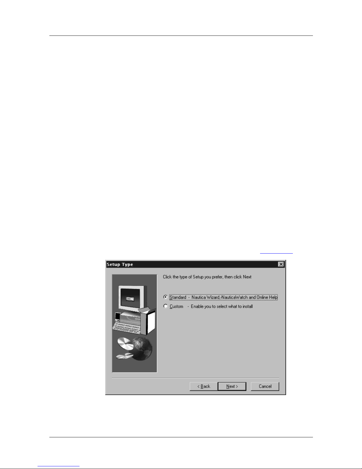
• Window 5: The Setup Type window opens (Figure 1-1
Next to continue, or Back to return to Window 3.
).
Figure 1-1. Setup Type Window
1-2 302269-A Rev.00
Page 23
You can either:
Getting Started
Select
Standard (the default) to move directly into the
Installation Assistant.
Select the
Custom option which allows you to specify
exactly what parts of the software you want to install before
starting the Installation Assis tant. Click on
Back to return to Window 4.
or
Note:
If you are a first time user of Nautica Wizard, it is
Next to continue
recommended that you select the Standard option. Additional
software elements can be added at a later time by running the
Nautica Wizard setup program again, then clicking on the
Custom option (Figure 1-1
) and selecting the parts of the
program you want to install.
• Window 6: Select a Program Folder into which all
application icons are installed. Click on
Back to return to Window 5.
Next to continue or
The installation software copies Nautica Wizard and Nautica
Watch to your PC, creates the program groups and starts
Nautica Wizard.
Note:
To run the CD in futu re without starting the installation
program, hold down the [SHIFT] key on the keyboard as you
insert the CD into your PC.
When Nautica Wizard opens, the Installation Assistant (software
that allows you to enter configuration information for the router)
starts automatically only if there are no other Nautica routers on
the LAN and the router you are installing is still in its
unconfigured state.
For information about starting the Installation Assistant manually ,
refer to page 1-5
.
Before the setup program starts the Installation Assistant, ensure
you have the following information:
302269-A Rev.00 1-3
Page 24

Nautica Wizard Installation Guide
European Requirements
• Your unique IP address
• Your subnet mask
• The name of your Nautica router
• The ISDN telephone number of the unit you want to call
• Any password you have been asked to use (optional)
North American Requirements
• Your unique IP address
• Your subnet mask
• The name of your Nautica router
• The ISDN telephone number of the unit you want to call
• Any password you have been asked to use (optional)
• The central office switch type used by your telephone
company
• Your local ISDN telephone numbers
• Your SPIDs (Service Profile Identifiers)
1-4 302269-A Rev.00
Page 25
Using the Installation Assistant
The Installation Assistant allows you to enter basic configuration
information into your Nautica router. How you access the
Installation Assistant depends on your configuration:
• If you r r outer is the only Nautica router on your n etw o rk, t he
Installation Assistant starts automatically when Nautica
Wizard open s for the f irst time.
• If there is more than one Nautica router on your LAN, or if
the unit is already configured, you must start it manually.
Starting the Installation Assistant Manually
To start the Installation Assistant manually, the router that you
want to set up needs to ha ve all its current conf iguration erased. If
a unit has no configuration, its name in the Nautica Wizard
window appears as “NoConfig,” and the graphical representation
of the unit is blue.
Getting Started
Erasing a Router Configuration
Caution:
to save the existing configuration to a file before erasing it from
the router.
To erase a router’s configuration and set it back to the factory
defaults, use one of the following procedures:
Nautica Wizard cannot undo an erase. It may be best
Procedure Option 1
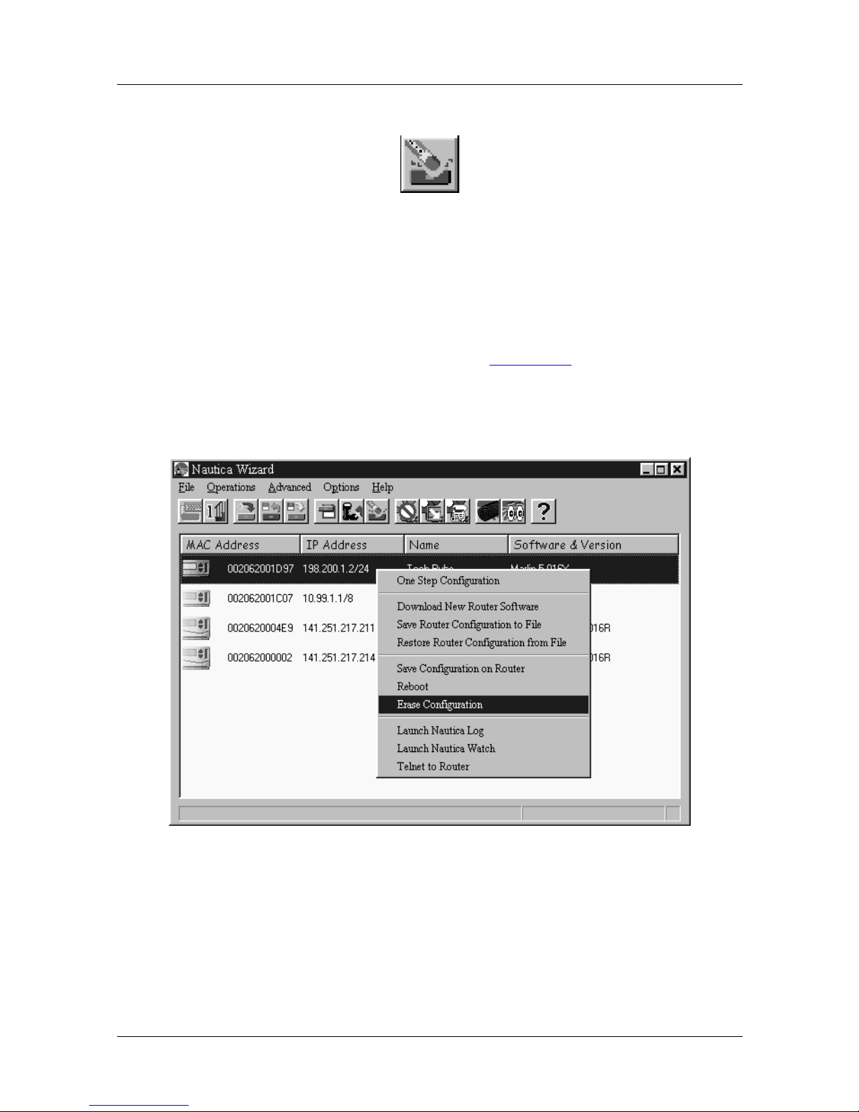
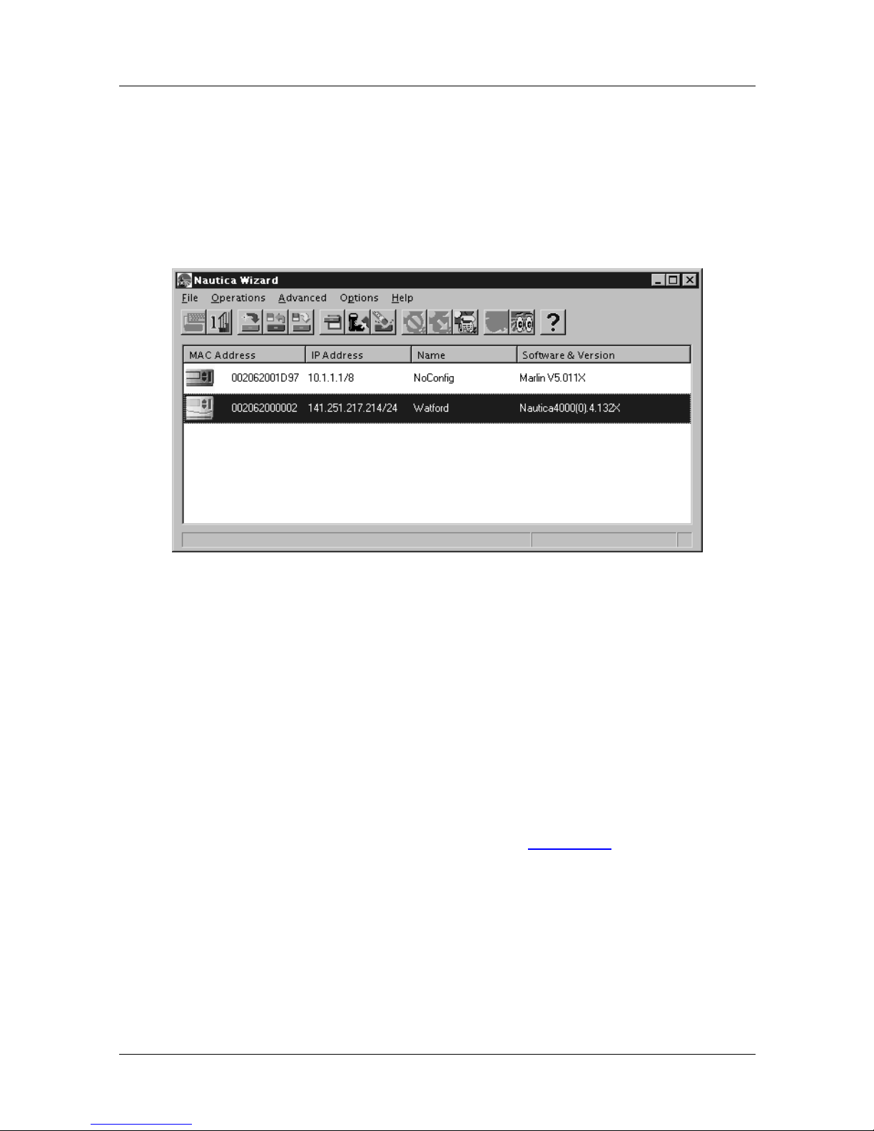
1. Select the unit in the Nautica Wizard window (Figure 1-2)
by clicking on its line.
302269-A Rev.00 1-5
Page 26

Nautica Wizard Installation Guide
Figure 1-2. Nautica Wizard Window
2. Then select Operations > Erase Configuration (Figure
1-3), or click once on the Erase Configuration button
(Figure 1-4)
in the toolbar.
Figure 1-3. Nautica Wizard Operations Menu
1-6 302269-A Rev.00
Page 27
Getting Started
Figure 1-4. Erase Configuration Button
Procedure Option 2
1. Position the cursor over the selected router line in the
Nautica Wizard window (Figure 1-2
mouse button once.
2. In the Quick menu that appears, select the Erase
configuration command with the left mouse button.
) and press the right
Figure 1-5. Nautica Wizard Quick Menu
302269-A Rev.00 1-7
Page 28
Nautica Wizard Installation Guide
Once the configuration has been erased, the graphical
representation of the router will change to blue in the Nautica
Wizard window to show that it is unconfigured. Only
unconfigured routers can be set up us ing the Installation
Assistant.
Figure 1-6. Nautica Wizard with Unconfigured Router
Configuring a Router Using the Installation Assistant
To start the Installation Assistant, use one of the following
procedures:
Procedure Option 1
1. Select the router to be conf igur ed by clicking on it once in
the Nautica Wizard window (Figure 1-2
).
1-8 302269-A Rev.00
Page 29
Getting Started
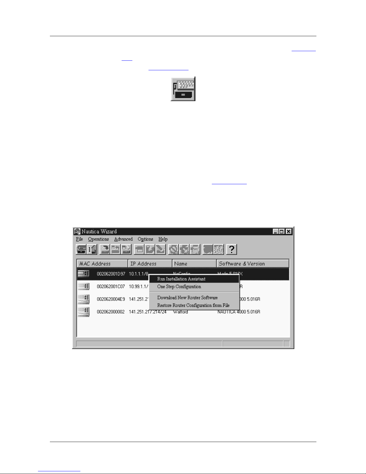
2. Click on Operations > Run Installation Assistant (Figure
1-3) or click on the Run Installation Assistant icon in the
toolbar (Figure 1-7)
.
Figure 1-7. Run Installation Assistant Button
Procedure Option 2
1. Position the cursor over the selected router in the Nautica
Wizard window and press the right mouse button once.
In the menu that appears (Figure 1-8
option, Run Installation Assistant, by clicking on it once
with the left mouse button.
), select the first
Figure 1-8. Nautica Wizard Configuration Quick Menu
302269-A Rev.00 1-9
Page 30
Nautica Wizard Installation Guide
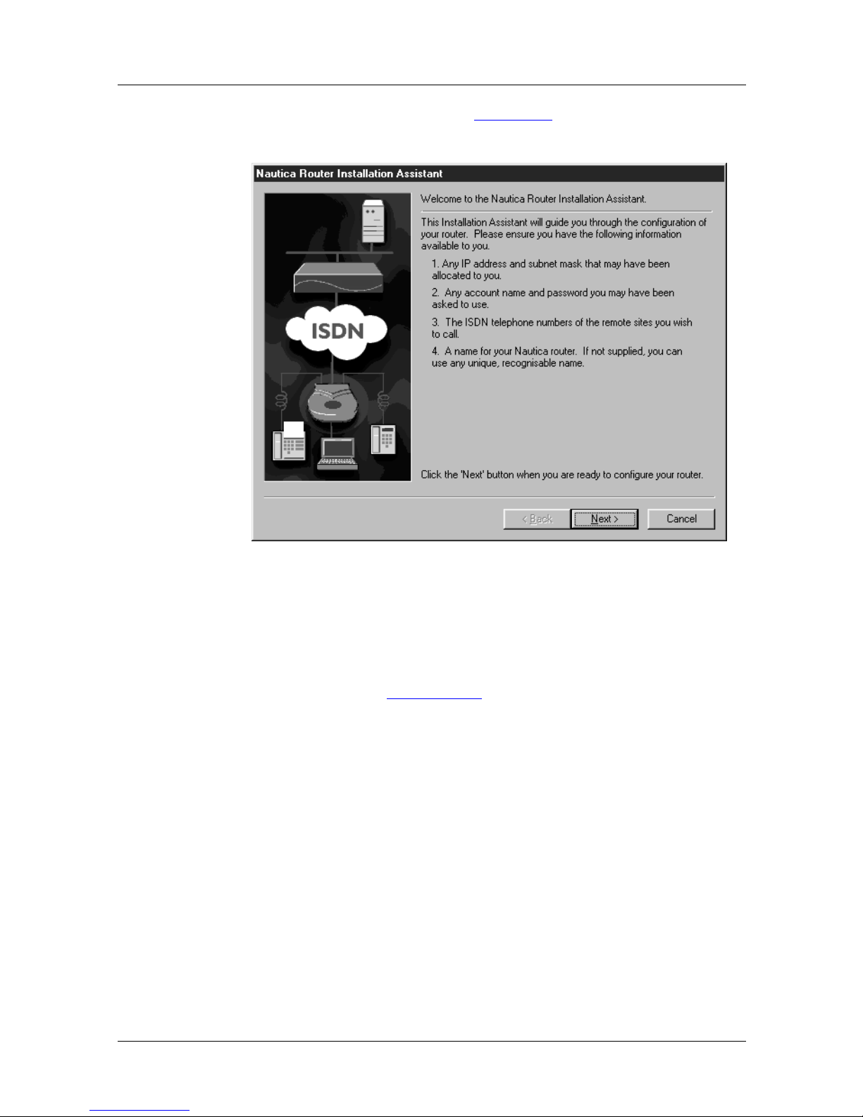
The first screen that appears (Figu r e 1-9), lists all the options you
need to configure your router.
Figure 1-9. Nautica Wizard Installation Assistant Checklist
To complete the configuration.
1. Proceed with the installation if you have all of this
information (Figure 1-9)
available.
1-10 302269-A Rev.00
Page 31

Getting Started
2. Click on the Next button and you move into the next
Installation Assistant window:
Figure 1-10. Your Network and ISDN Connectivity Window
3. Select whether you have one or more than one PC
connected to your router. The default is one PC.
4. Consult the chapter that refers to your installation type:
• An Internet Service Provider (ISP) - Chapter 2
• An intranet or corporate network - Chapter 3
• Both an ISP and an Intranet - Chapter 4
• Something other than these options - Chapter 5.
An ISP is an organization, such as America Online, that
allows you to access the resources and services of the
Internet.
An intranet is a network that can b e accessed only within
a company by its emplo yees and partners. An e xample of
an intranet is the Bay Networks Partnerweb
™
.
302269-A Rev.00 1-11
Page 32

Page 33

Chapter 2
Connecting to an Internet Service
Provider
An Internet Service Provider (ISP) is a vendor whose service
allows your computer to access the Internet. Nautica Wizard
configures your router to connect to the ISP using Network
Address Translation (NAT). For a detailed explanation of NAT,
refer to the Concepts topic of the Nautica Wizard Help file or to
the Nautica Configuration Wizard 5 Reference Guide on the CD
that accompanies this installation guide.
This chapter contains the following sections:
• ISDN Connectivity (page 2-2
• Connecting to the ISDN Network (page 2-5
• ISP Account Details (page 2-8
• Completing the Connection (page 2-11
• Cancelling an Automatic ISDN Call (page 2-15
• Dealing with a Call Failure (page 2-17
• Redialing an ISDN Number (page 2-17
)
)
)
)
)
)
)
302269-A Rev.00 2-1
Page 34

Nautica Wizard Installation Guide
ISDN Connectivity
To connect to an ISP using the Installation Assistant, it is
important that you select this o ption in the Your Network and
ISDN Connectivity window of the Installation Assistant (Figure
2-1).
Figure 2-1. Your Network and ISDN Connectivity Window
With this option selected, click on the
Next button to move you
into the Connecting to an Internet Service Provider window
(Figure 2-2
2-2 302269-A Rev.00
).
Page 35

Connecting to an Internet Service Provider
Figure 2-2. Connecting to an Internet Service Provider Window
The parameters in this window are as follows:
Parameter: IP Address Supplied
Function: Generally, your ISP supplies you with an IP address. If it
has not done so or you cannot get one, click No.
302269-A Rev.00 2-3
Page 36

Nautica Wizard Installation Guide
Parameter: IP Address
Function: If you have been given an IP address, enter it into the IP
address field.
An IP address uniq uely i d ent ifies your router and mak es
the passing of information possib le. For more
information on IP addresses and TCP/IP in gen eral, refer
to the Concepts topic in the Nautica Wizard Help file.
Parameter: Subnet Mask
Function: Enter the subnet mask that needs to be applied to your IP
address.
Subnet masks identify distinct, logical collections of
devices on a network, and group them together. They
allow the router to determine whether another IP address
is local to your router.
2-4 302269-A Rev.00
Page 37

Connecting to an Internet Service Provider
Connecting to the ISDN Network
If you are in North America, the Connecting to the ISDN
Network wind ow (Figure 2-3
) appears:
Figure 2-3. Connecting to the ISDN Network
The parameters in this window are as follows:
302269-A Rev.00 2-5
Page 38

Nautica Wizard Installation Guide
Parameter: Switch Type
Function: The switch type is the type of ISDN line you are
operating. The default setting here is National ISDN,
but other values such as AT&T Custom Point to Point,
AT&T Custom Multipoint and Nortel DMS Custom can
also be selected.
Select the ISDN line type. This informatio n is supplied
by your telephone company. If you are unsure of the
switch type, select the Autose nse option.
Note: Selecting Autosense disables the two SPID fields.
Parameter: Area Code
Function: Enter the local area code here.
Parameter: First Telephone Number
Function: Local numbers are provided b y your tel ephone compan y .
If your switch type is AT&T Custom Point to Point, you
do not have to enter a local number.
Enter any local numbers provided by your telephone
company.
Parameter: Second Telephone Number
Function: Local numbers are provided b y your tel ephone compan y .
If your switch type is AT&T Custom Point to Point, you
do not have to enter a local number.
2-6 302269-A Rev.00
Enter any local numbers provided by your telephone
company.
Page 39

Connecting to an Internet Service Provider
Parameter: First SPID
Function: Service Profile Identifiers (SPIDs) are provided by your
telephone company. If your switch type is AT&T
Custom Point to Point, you do not have to enter a SPID.
For all other line types there should be a SPID
corresponding to each local ISDN telephone number.
Enter any SPID provided by your telephone company.
Parameter: Second SPID
Function: Service Profile Identifiers (SPIDs) are provided by your
telephone company. If your switch type is AT&T
Custom Point to Point, you do not have to enter a SPID.
For all other line types there should be a SPID
corresponding to each local ISDN telephone number.
Enter any SPID provided by your telephone company.
302269-A Rev.00 2-7
Page 40

Nautica Wizard Installation Guide
ISP Accoun t Details
Once the information has been entered into this window, click on
Next button to open the Internet Service Provider Account
the
Details window (Figure 2-4
).
Figure 2-4. Internet Service Provider Account Details Window
The parameters in this window are as follows:
Parameter: Username
Function: This is the account name given to you by the ISP. Enter
this information exactly as you received it.
Usernames are case sensitive.
2-8 302269-A Rev.00
Page 41

Connecting to an Internet Service Provider
Parameter: Password
Function: If you have been given a password, enter this data into
the password field. Remember that the password is case
sensitive.
Anything typed into this field is displayed as a series of
asterisks for security purposes. Passwords provide extra
security for your router.
This password is used by the router to identify you to
your ISP.
Parameter: Confirm Password
Function: The passwo rd needs to be entered again in the Confirm
Password field.
When you click on the Next button, the password
entered here is matched against the password entered in
the Password field. If there is a difference, a dialog box
appears advising that the passwords are incorrect. You
must enter the password again before you can leave this
window.
Parameter: Telephone Number
Function: Enter into this field (Figure 2-4)
number given to you by the ISP. This number is the
connection number for your router and not any other
numbers you might use when dealing with the ISP.
the ISDN telephone
302269-A Rev.00 2-9
Page 42

Nautica Wizard Installation Guide
Parameter: Path Name
Function: The name you want the path t o the ISP t o be called. This
is an optional field.
Entering a value here names the path that reaches the
ISP. This path name can be seen by selecting the router
in the Nautica W izard windo w (Figure 2-7
on Advanced > Paths > Configuration once the
Installation Assistant is comple te.
Selecting Advanced > Paths > Configuration causes the
Paths Ta ble (Figure 2-5
), and clicking
) to appear:
Figure 2-5. Paths Table
In the Paths Table you can see the name you have assigned to the
ISP Account path, as well as the path to the local LAN (LAN01 ).
2-10 302269-A Rev.00
Page 43

Connecting to an Internet Service Provider
Completing the Connection
After you have entered the ISDN telephone number, click on the
Next button. The Completing the Configuration window appears
(Figure 2-6
).
Figure 2-6. Completing the Configuration Window
The parameters in this window are as follows:
302269-A Rev.00 2-11
Page 44

Nautica Wizard Installation Guide
Parameter: Router Name
Function: This is an arbitrary name you can use to identify your
router. By default, the Installation Assistant enters your
user name here, although you can overwrite this if you
require.
If you hav e mo re than one ro uter on your netw or k, using
names allows you to locate and configure them more
effectively. Th is is no t the accou nt nam e given to you by
the ISP, although you can use this name here if you wish.
Parameter: IP Address
Function: This is the IP address of the router (not the ISP). To the
right of this field, the Installation Assistant shows you
the IP address(es) assigned to your PC.
Generally the IP address of the router is one greater than
that of the PC. For example, if the PC’s IP address is
141.14.10.0, the IP address of the router is 141.14.10.1.
The IP address is entered automatically b y the router, but
you can change this if necessary.
Parameter: Mask
Function: This is the subnet mask applied to your router’s IP
address. Unless you change the IP address, this field is
entered automatically by the Installatio n Assistant.
Parameter: Router Password
Function: An additional password to protect your router.
This password protects the configuration on your router
and the manager interface. If you enter a password here
(this is optional), the password must be entered every
time you look at or amend the con figuration of the
router. For security purposes, the password is displayed
as a series of asterisks.
2-12 302269-A Rev.00
Page 45

Connecting to an Internet Service Provider
Parameter: Confirm Password
Function: To ensure that you have typed the password correctly,
enter it again into the Confirm Password field.
The passwords are checked against each other when you
click on the Finish button. If ther e are an y discrepancies,
a dialogue box advises you of this. Enter the passwords
again and click on the
Finish button once more.
Parameter: Test Call
Function: If you select Yes to the this option, your router calls the
telephone number entered into the Internet Serv ice
Provider Account Details window (Figure 2-4
is made when you click on the
Finish button.
). This call
302269-A Rev.00 2-13
Page 46

Nautica Wizard Installation Guide
If the call is successful, and you did not enter a Path
Name, a path is created on your router with the name of
the Challenge Handshake Authentication Control
(CHAP) ID of the router you are calling.
If your router is not CHAP challenged and you did not
enter a Path Name
on the router.
, a path called RemotePPP is created
If you have entered a Path Name
, this is the name of the
path that is created on the router. The path type is Point
to Point Protocol (PPP), un less you are connecting to a
Nautica Router when it is a Nautica Protocol path.
If your initial call fails, refer to the Dealing with a Call
Failure section of this chapter. F or more information
about CHAP passwords, refer to the Concepts topic of
the Nautica Wizard help file and the Nautica
Configuration Wizard 5 Reference Guide on the CD that
accompanies this installation guide.
2-14 302269-A Rev.00
Page 47

Connecting to an Internet Service Provider
Cancelling an Automatic ISDN Call
If you agreed to make a call to the ISP, the call needs to be
manually cancelled after about one minute. Cancel the call by:
1. Selecting the router on which the call is running in the
Nautica Wizard window (Figure 2-7
).
Figure 2-7. The Nautica Wizard Window
2. Clicking on Advanced > ISDN > Stats.
3. The ISDN Ports Table appears (Figure 2-8)
.
302269-A Rev.00 2-15
Page 48

Nautica Wizard Installation Guide
Figure 2-8. ISDN Ports Table
4. In the ISDN Ports table (Figure 2-8
), click once on the
port carrying the call (for the Status of the call).
5. Click on Clear.
6. Click on OK to retur n you to the Nautica Wizard window.
For more information on ISDN statistics, refer to the Nautica
Configuration Wizard 5.0x Reference Guide on the CD that
accompanies this installation guide.
2-16 302269-A Rev.00
Page 49

Connecting to an Internet Service Provider
Dealing with a Call Failure
If the call fails, you are advised of this failure. Calls can fail for
many reasons. As a guide, check the following:
• The ISDN number on the path is correct.
• The passwords for the path are the same as those for the ISP.
• There is a physical connection between your router and an
ISDN wall outlet.
Refer to the Nautica Configuration Wizard 5 Reference Guide on
the CD that accompanies this installation guide for details on how
to amend ISDN numbers and CHAP passwords on paths.
Redialing an ISDN Number
If you need to re-call an ISDN number after a call failure, do the
following:
1. Select the router on which to place the call in the Nautica
Wizard window (Figure 2-7
2. Click on Advanced > Paths > Configu ration.
3. The Paths Table appears (Figure 2-9
).
).
302269-A Rev.00 2-17
Page 50

Nautica Wizard Installation Guide
Figure 2-9. The Paths Table
4. In the Paths Table, click on the path that points to the
router you want to call.
5. Click once on Call.
6. Click on OK to close the window.
You need to clear the call after about a minute (for instructions,
see page 2-15
).
2-18 302269-A Rev.00
Page 51

Chapter 3
Connecting to an Intranet
Rather than configuring your Nautica router to connect into an
Internet Service Provider (ISP - Chapter 2), it is possible to
connect into an intranet or corporate network.
Using your router to attach to an intranet means the remote office
can use all the facilities and data provided to people working in
the central office.
This chapter includes the following sections:
• ISDN Connectivity (page 3-2
• Transport Protocols (page 3-5
• Connecting to the ISDN Network (page 3-11
• Intranet Account Details (page 3-14
• Completing the Configuration (page 3-16
• Cancelling an Automatic ISDN Call (page 3-19
• Dealing with a Call Failure (page 3-20
)
)
)
)
)
)
)
302269-A Rev.00 3-1
Page 52

Nautica Wizard Installation Guide
ISDN Connectivity
The quickest way to connect your ro uter to an intranet is by using
the Installation Assistant. To run the Installation Assistant, do the
following:
1. Click on the router to be configured in the Nautica
Wizard window (it is blue).
Figure 3-1. Nautica Wizard Window
2. If the router already contains configuration information,
erase this or save the conf iguration to a f ile and then erase
it.
3. Start the Installation Assistant using any of these three
options:
• Click on the Run Installation Assistant button (Figure
3-2) in the toolbar:
Figure 3-2. Run Installation Assistant Button
3-2 302269-A Rev.00
Page 53

Connecting to an Intranet
• Click on Operations > Run Installation Assistant.
• Right click on the highlighted router and select Run
Installation Assistant from the Quick m enu by clicking
on it once with the left mouse button (Figure 3-3)
:
Figure 3-3. Nautica Wizard Quick Menu
4. If you have all the information to hand in the first
window, click on the Next button.
302269-A Rev.00 3-3
Page 54

Nautica Wizard Installation Guide
5. In the Your Network and ISDN Connectivity window,
select the intranet or Corporate Network option.
Figure 3-4. Your Network and ISDN Connectivity Window
Click on the Next button to proceed with the installation.
3-4 302269-A Rev.00
Page 55

Transport Protoc ols
After you hav e selected the intranet or Corpor ate Netw ork option
in the Your Network and ISDN Connectivity window (Figure
3-4), click on the Next button. The Connecting to an intranet
window appears (Figure 3-5
Connecting to an Intranet
).
Figure 3-5. Connecting to an Intranet Window
The parameters in this window are as follows:
302269-A Rev.00 3-5
Page 56

Nautica Wizard Installation Guide
Parameter: TCP/IP
Function: Transport Control Prot ocol/Intern et Protocol (TCP/IP) is
the main protocol used by PCs to move data around the
network. If your network uses TCP/IP, leave this option
selected. If you are unsure which protocol is being used
on your PC, check with your system administrator.
Parameter: IPX
Function: Internet Packet Exchange (IPX) is a pr otocol used b y the
Novell Co rpo rat ion o n t heir n et wo rks . If you are us i ng a
Novell network, select the IPX option here. If you are
unsure which protocol is being used on your PC, check
with your system administrator.
3-6 302269-A Rev.00
Page 57

Connecting to an Intranet
Connecting to an Intranet using TCP/IP
If you select the TCP/IP option in the Connecting to an intranet
window (Fig ure 3-5
), click on the
to an intranet with IP window appears (Figure 3-6
button and the Connecting
Next
).
Figure 3-6. Connecting to an Intranet with IP Window
The parameters in this window are as follows:
302269-A Rev.00 3-7
Page 58

Nautica Wizard Installation Guide
Parameter: Have IP Address
Function: If you have been provided with an IP address by your
systems administrator, click on Yes. If you do not have
an IP address, click on No and move onto the next
window.
Parameter: Enter IP Address
Function: If you have been supplied with an IP address, enter it in
this field.
Parameter: Enter Subnet Mask
Function: If you have entered an IP add ress, enter the subnet mask
for that address into this field.
3-8 302269-A Rev.00
Page 59

Connecting to an Intranet
Connecting to an Intranet using Novell IPX
If you selected the Novell IPX option in the Connecting to an
Intranet window (Figure 3-5
Connecting to an Intranet with IPX window appears (Figure 3-7
), click on the
Next
button and the
).
Figure 3-7. Connecting to an Intranet with IPX Window
The parameters in this window are as follows:
302269-A Rev.00 3-9
Page 60

Nautica Wizard Installation Guide
Parameter: Autolearn Network Number
Function: If you do not understand Novell IPX, or have not been
supplied with your network details, click on Yes at the
top of this window. This turns on a feature known as
“autolearn.” Autolearn discov er s the netwo rk n umb er of
your connection automatically.
Note: The network number is only learned if the local server is
attached to the LAN.
Parameter: Network Number
Function: If you know the number of the network, enter it here.
Parameter: Network Type
Function: If you know the network type, enter it here.
Parameter: SAP Filtering
Function: Service Advertising Protocols (SAPs) advise you of
services, such as print servers, that are available on the
network. As you are connecting into an intranet, you
may not need to know about all the services pro vi de d by
that network. Clicking on Yes for this option allows you
to set up SAP filters to filter out the SAPs you do not
want to receive.
For more information on SAP filtering, refer to Nautica
Configuration Wizard 5 Reference Guide on the CD that
accompanied this installation guide.
3-10 302269-A Rev.00
Page 61

Connecting to the ISDN Network
If you are in North America, the Connecting to the ISDN
Network wind ow (Figure 3-8
) appears:
Connecting to an Intranet
Figure 3-8. Connecting to the ISDN Network
The parameters in this window are as follows:
302269-A Rev.00 3-11
Page 62

Nautica Wizard Installation Guide
Parameter: Switch Type
Function: The switch type is the type of ISDN line you are
operating. The default setting here is National ISDN,
but other values such as AT&T Custom Point to Point,
AT&T Custom Multipoint and Nortel DMS Custom can
also be selected.
Select the ISDN line type. This informatio n is supplied
by your telephone company. If you are unsure of the
switch type, select the Autose nse option.
Note: Selecting Autosense disables the two SPID fields.
Parameter: Area Code
Function: Enter the local area code here.
Parameter: First Telephone Number
Function: Local numbers are provided b y your tel ephone compan y .
If your switch type is AT&T Custom Point to Point, you
do not have to enter a local number.
Enter any local numbers provided by your telephone
company.
Parameter: Second Telephone Number
Function: Local numbers are provided b y your tel ephone compan y .
If your switch type is AT&T Custom Point to Point, you
do not have to enter a local number.
3-12 302269-A Rev.00
Enter any local numbers provided by your telephone
company.
Page 63

Connecting to an Intranet
Parameter: First SPID
Function: Service Profile Identifiers (SPIDs) are provided by your
telephone company. If your switch type is AT&T
Custom Point to Point, you do not have to enter a SPID.
For all other line types there should be a SPID
corresponding to each local ISDN telephone number.
Enter any SPID provided by your telephone company.
Parameter: Second SPID
Function: Service Profile Identifiers (SPIDs) are provided by your
telephone company. If your switch type is AT&T
Custom Point to Point, you do not have to enter a SPID.
For all other line types there should be a SPID
corresponding to each local ISDN telephone number.
Enter any SPID provided by your telephone company.
302269-A Rev.00 3-13
Page 64

Nautica Wizard Installation Guide
Intranet Account Details
Click on the Next button in the Connecting to an Intranet with
IPX window (Figure 3-7
appears (Figure 3-9
).
). The Intranet Account Details window
Figure 3-9. Intranet Account Details Window
The parameters in this window are as follows:
3-14 302269-A Rev.00
Page 65

Connecting to an Intranet
Parameter: Username
Function: Enter the account n a me her e exactly as it is given t o you
by the system administrator . Username is a case sensiti ve
field.
Parameter: Password
Function: If you have a password, enter it here exactly as you have
been given it. This field is case sensitive.
Parameter: Confirm Password
Function: If you do have a password, enter it again into the
Confirm Password field. When you click on the Next
button, the two pa sswords are matched. You only move
to the next window if they agree. If they do not match,
you are advised of this and need to enter the passwords
again.
Parameter: Telephone Number
Function: Enter the ISDN telephone number of the intranet into the
next field on this form.
Parameter: Path Name
Function: The fi nal field in the window, Path Name, is an optional
field. By default a path is created to the new router, the
name of this path is set once the call is made. Entering a
name here allows you to apply your own name to this
path.
302269-A Rev.00 3-15
Page 66

Nautica Wizard Installation Guide
Completing the Configuration
After you have entered the ISDN telephone number, click on the
Next button. The Completing the Configuration window appears
(Figure 3-10
).
Figure 3-10. Completing the Configuration Window
The parameters in this window are as follows:
3-16 302269-A Rev.00
Page 67

Connecting to an Intranet
Parameter: Name
Function: Router Name is an arbitrary name you can use to
identify your ro uter. If you hav e mor e than on e rout er on
your network, using names allows you to locate and
configure them more effectively. This is not the account
name given you by the Intranet manager, although you
can use this name here if you wish.
Parameter: IP Address
Function: Enter the IP address for the router. A router’s IP address
is generally one higher than that of your PC.
The Completing the C onf ig uration window shows the IP
address(es) assigned to your PC to the right of this field.
Enter a router address for your router.
For exam ple, if t he IP address of th e PC is 1 41.100 .10.1,
the address of the router could be 141.100.10.2.
Parameter: Mask
Function: Enter a subnet mask that is applied to the IP address of
the router.
Parameter: Password
Function: The Router Password field is an additional password to
protect your router. If you enter a password here (this is
optional), the password must be entered every time you
look at or amend the configuration details of the router.
The password is displayed as a series of asterisks for
security purposes.
302269-A Rev.00 3-17
Page 68

Nautica Wizard Installation Guide
Parameter: Confirm Password
Function: Enter the password again into the Confirm Password
field. The passwords are checked against each other
when you click on
a dialog box advises you of this. Enter the passwords
again and click on
Parameter: Test Call
Function: If you click on Yes for this option, making an automatic
call to the telephone number, your router calls the
telephone number entered into the Intranet Account
Details window (Figure 3-9
click on the Finish button.
Finish. If there are any discrepancies,
Finish once more.
). This call is made when you
If the call is successful and you have not entered a name
in the path name field on the Intranet Account Details
window (Figu re 3-9
), and your router is presented with a
Challenge Handshake Authentication Protocol (CHAP)
password, a path is created on your rout er with the nam e
of the CHAP ID of the router you are calling.
If your router is n ot CHAP chal lenge d, and you ha v e no t
entered a name in the path name field on the Intranet
Account Details window (Figure 3-9
), a path called
RemotePPP, or RemoteNautica is created on the router.
Note:
RemoteNautica is only used as a path na m e if the
Nautica Path option is selected when configuring a CLAM,
Marlin or Nautica 4000.
If you click on No to the initial call option, a path called
RemotePPP or RemoteNautica is created on the router.
3-18 302269-A Rev.00
Page 69

Connecting to an Intranet
If your initial call fails, refer to the Dealing with a Call
Failure section of this chapter. F or more information
about CHAP passwords, refer to the Concepts topic of
the Nautica Wizard help file and the Nautica
Configuration Wizard 5 Reference Guide on the CD that
accompanied this installation guide.
Once all the information is entered into the Completing
the Configuration window (Figure 3-10
Finish button. You are returned to the Nautica Wizard
window.
Cancelling an Automatic ISDN Call
If you agreed to make a call to the ISP, the call needs to be
manually cancelled after about one minute. Cancel the call by:
), click on the
1. Selecting the router on which the call is running in the
Nautica Wizard window (Figure 3-11
Figure 3-11. The Nautica Wizard Window
2. Clicking on Advanced > ISDN > Stats.
).
3. The ISDN Ports Table appears (Figure 3-12)
302269-A Rev.00 3-19
.
Page 70

Nautica Wizard Installation Guide
Figure 3-12. ISDN Ports Table
4. In the ISDN Ports table, click once on the port carrying
the call (the TxUtil and RxUtil are greater than 00).
5. Click on the Clear button.
Dealing with a Call Failure
If the call fails, you are advised of this failure. Calls fail for many
reasons. As a guide, check the following:
• The ISDN number on the path is correct.
• The passwords for the path are the same as those for the ISP.
• There is a physical connection between your router and an
ISDN wall outlet.
3-20 302269-A Rev.00
Page 71

Redialling an ISDN Number
If you need to re-call an ISDN number after a call failure, do the
following:
1. Select the router on which to place the call in the Nautica
Wizard window (Figure 3-11
2. Click on Advanced > Paths > Configu ration.
Connecting to an Intranet
).
3. The Paths Table appears (Figure 3-13
Figure 3-13. The Paths Table
):
4. In the Paths Table, select the path that links to the remote
site.
5. Click once on Call.
6. Click on OK to close the window.
You need to cancel the call after about a minute (for instructions,
see page 3-19
302269-A Rev.00 3-21
).
Page 72

Page 73

Chapter 4
Connecting to Both an ISP and an
Intranet
It is possible to use your router to connect into an intranet and an
Internet Service Provider (ISP).
An intranet is an enterprise-wide network. Home wo rkers or
people at remote offices use their routers to connect into the
central off ice intranet. In this way they can access all the data and
services available on that network. An ISP allows your computer
to access the Internet.
This chapter includes the following sections:
• ISDN Connectivity (page 4-2
• ISP Account Details (page 4-7
• Transport Protocols (page 4-10
• Connecting to the ISDN Network (page 4-16
• Intranet Account Details (page 4-19
• Completing the Configuration (page 4-21
• Cancelling an Automatic ISDN Call (page 4-25
• Dealing with a Call Failure (page 4-26
• Riddling an ISDN Number (page 4-26
)
)
)
)
)
)
)
)
)
302269-A Rev.00 4-1
Page 74

Nautica Wizard Installation Guide
ISDN Connectivity
To connect to an ISP and an intranet using the Installation
Assistant, do the following:
1. Click on the router to be configured in the Nautica
Wizard window (Figure 4-1
).
Figure 4-1. Nautica Wizard Window
2. If the router already contains configuration information,
erase this or save the conf iguration to a f ile and then erase
it.
3. Start the Installation Assistant by completing one of the
following:
• Click on the Run Installation Assistant button in the
toolbar.
Figure 4-2. Run Installation Assistant Button
4-2 302269-A Rev.00
Page 75

Connecting to Both an ISP and an Intranet
• Click on Operations > Run Installation Assistant.
Figure 4-3. Nautica Wizard Operations Menu
• Right click on the highlighted router and select Run
Installation Assistant from the Quick m enu.
Figure 4-4. Nautica Wizard Quick Menu
4. If you have all the information to hand in the first
Installation Assistant window, click on the Next button.
302269-A Rev.00 4-3
Page 76

Nautica Wizard Installation Guide
In the Your Network and ISDN Conn ectivity window (Figure
4-5), select the Both an ISP and an Intranet option.
Figure 4-5. Your Network and ISDN Connectivity Window
With this option selected, click on the
button to move you
Next
into the Connecting to an Internet Service Provider window
(Figure 4-6
).
4-4 302269-A Rev.00
Page 77

Connecting to Both an ISP and an Intranet
Figure 4-6. Connecting to an Internet Service Provider Window
The parameters in this window are as follows:
Parameter: Have IP Address
Instructions: Generally , you r ISP suppl ies you with an IP addres s. If it
has not done so, or if you cannot get one, click on No.
302269-A Rev.00 4-5
Page 78

Nautica Wizard Installation Guide
Parameter: IP Address
Function: If you have been given an IP address, enter it into the IP
address field. An IP address uniquely identifies your
router and makes the passing of information possible.
For more information on IP addresses and TCP/IP in
general, refer to the Concepts topic in the Nautica
Wizard Help file.
Parameter: Subnet Mask
Function: Next, enter the subnet mask that needs to be applied to
your IP addresses. Subnet masks allow more IP
addresses to be used, but the router needs to kno w which
subnet mask it is using in order to pass this information
on to other routers. For more information on subnet
masks and TCP/IP in general, refer to the Concepts topic
of the Nautica Wizard Help file.
4-6 302269-A Rev.00
Page 79

ISP Accoun t Details
Once the information has been entered into this window, click on
Next button to open the Internet Service Provider Account
the
Details window (Figure 4-7
Connecting to Both an ISP and an Intranet
).
Figure 4-7. Internet Service Provider Account Details Window
The parameters in this window are as follows:
302269-A Rev.00 4-7
Page 80

Nautica Wizard Installation Guide
Parameter: Username
Function: Username is the account name given to you by the ISP.
Enter this information exactly as you received it.
Usernames are case sensitive.
Parameter: Password
Function: If you have been given a password, enter this data into
the password field. For security purposes, anything
typed into this field is displayed as a series of asterisks.
Passwords provide extra security for your router. Only
routers that know the password can access information
via your router, and, conversely, you can only access
information from routers if you know their password.
Parameter: Confirm Password
Function: The passwo rd needs to be entered again in the Confirm
Password field. When you click on the Next button, the
password entered here is matched against the password
entered in the Password field. If there is a difference, a
dialog box appears advising that the passwords are
incorrect. You must enter the passwords again before
you can leave this window.
Parameter: Telephone Number
Function: Enter into this field th e ISDN telephone number gi v en to
you by the ISP. This number is the connection number
for your router (an d not an y ot her numb er you migh t use
when dealing with the ISP).
4-8 302269-A Rev.00
Page 81

Connecting to Both an ISP and an Intranet
Parameter: Path Name
Function: The name you want the path to the connection to be
called. This is an optional field.
Entering a value here names the path that reaches the
remote connection. This path name can be seen by
selecting the router in the Nautica Wizard window
(Figure 4-1
), and clicking on Advanced > Paths >
Configuration once the Installation Assistant is
complete.
Selecting Advanced > Paths > Configuration causes the
Paths Ta ble (Figure 4-8
) to appear:
Figure 4-8. Paths Table
In the Paths Table you can see the name you have assigned to the
remote connection path, as well as the path to the local LAN
(LAN01).
302269-A Rev.00 4-9
Page 82

Nautica Wizard Installation Guide
Transport Protoc ols
After you have selected the Intranet or Corporate Network option
in the Your Network and ISDN Connectivity window (Figure
4-5), click on the Next button. The Connecting to an Intranet
window appears (Figure 4-9
).
Figure 4-9. Connecting to an Intranet Window
The parameters in this window are as follows:
4-10 302269-A Rev.00
Page 83

Connecting to Both an ISP and an Intranet
Parameter: TCP/IP
Function: Transport Control Prot ocol/Intern et Protocol (TCP/IP) is
the main protocol used by PCs to move data around the
network. If your network uses TCP/IP, leave this option
selected. If you are unsure which protocol is being used
on your PC, check with your system administrator.
Parameter: IPX
Function: Internet Packet Exchange (IPX) is a pr otocol used b y the
Novell Co rpo rat ion o n t heir n et wo rks . If you are us i ng a
Novell network, select the IPX option here. If you are
unsure which protocol is being used on your PC, check
with your system administrator.
For more information on Transmission Control Protocol/Internet
Protocol (TCP/IP) and Novell Internetworking Packet Exchange
(IPX) refer to the Concepts topic in the Nautica Wizard Help file.
302269-A Rev.00 4-11
Page 84

Nautica Wizard Installation Guide
Connecting to an Intranet using TCP/IP
If you select the TCP/IP option in the Connecting to an Intranet
window (Fig ure 4-9
), click on the
to an Intranet with IP window appears (Figure 4-10
button and the Connecting
Next
).
Figure 4-10. Connecting to an Intranet with IP Window
The parameters in this window are as follows:
4-12 302269-A Rev.00
Page 85

Connecting to Both an ISP and an Intranet
Parameter: Have IP Address
Function: If you have been provided with an IP address by your
systems administrator, click on Yes. If you do not have
an IP address, click on No and move onto the next
window.
Parameter: Enter IP Address
Function: If you have been supplied with an IP address, enter it in
this field.
Parameter: Enter Subnet Mask
Function: If you have entered an IP add ress, enter the subnet mask
for that address into this field.
302269-A Rev.00 4-13
Page 86

Nautica Wizard Installation Guide
Connecting to an Intranet using Novell IPX
If you selected the Novell IPX option in the Connecting to an
Intranet window (Figure 4-9
Connecting to an Intranet with IPX window appears (Figure
4-11).
), click on the
Next
button and the
Figure 4-11. Connecting to an Intranet with IPX window
The parameters in this window are as follows:
4-14 302269-A Rev.00
Page 87

Connecting to Both an ISP and an Intranet
Parameter: Autolearn Network Number
Function: If you do not understand Novell IPX, or have not been
supplied with your network details, click on Yes at the
top of this window. This turns on a feature known as
“autolearn.” Autolearn discov er s the netwo rk n umb er of
your connection automatically.
Note: The network number is only learned if the local server is
attached to the LAN.
Parameter: Network Number
Function: If you know the number of the network, enter it here.
Parameter: Network Type
Function: If you know the network type, enter it here.
Parameter: SAP Filtering
Function: Service Advertising Protocol (SAPs), advise you of
services, such as print servers, that are available on the
network. As you are connecting into an intranet, you
may not need to know about all the services pro vi de d by
that network. Clicking on Yes for this option allows you
to set up SAP filters to filter out the SAPs you do not
want to receive.
For more information on SAP filtering, refer to Nautica
Configuration Wizard 5 Reference Guide on the CD that
accompanied this installation guide.
302269-A Rev.00 4-15
Page 88

Nautica Wizard Installation Guide
Connecting to the ISDN Network
If you are in North America, the Connecting to the ISDN
Network wind ow (Figure 4-12
) appears:
Figure 4-12. Connecting to the ISDN Network
The parameters in this window are as follows:
4-16 302269-A Rev.00
Page 89

Connecting to Both an ISP and an Intranet
Parameter: Switch Type
Function: The switch type is the type of ISDN line you are
operating. The default setting here is National ISDN,
but other values such as AT&T Custom Point to Point,
AT&T Custom Multipoint and Nortel DMS Custom can
also be selected.
Select the ISDN line type. This informatio n is supplied
by your telephone company. If you are unsure of the
switch type, select the Autose nse option.
Note: Selecting Autosense disables the two SPID fields.
Parameter: Area Code
Function: Enter the local area code here.
Parameter: First Telephone Number
Function: Local numbers are provided b y your tel ephone compan y .
If your switch type is AT&T Custom Point to Point, you
do not have to enter a local number.
Enter any local numbers provided by your telephone
company.
Parameter: Second Telephone Number
Function: Local numbers are provided b y your tel ephone compan y .
If your switch type is AT&T Custom Point to Point, you
do not have to enter a local number.
302269-A Rev.00 4-17
Enter any local numbers provided by your telephone
company.
Page 90

Nautica Wizard Installation Guide
Parameter: First SPID
Function: Service Profile Identifiers (SPIDs) are provided by your
telephone company. If your switch type is AT&T
Custom Point to Point, you do not have to enter a SPID.
For all other line types there should be a SPID
corresponding to each local ISDN telephone number.
Enter any SPID provided by your telephone company.
Parameter: Second SPID
Function: Service Profile Identifiers (SPIDs) are provided by your
telephone company. If your switch type is AT&T
Custom Point to Point, you do not have to enter a SPID.
For all other line types there should be a SPID
corresponding to each local ISDN telephone number.
Enter any SPID provided by your telephone company.
4-18 302269-A Rev.00
Page 91

Connecting to Both an ISP and an Intranet
Intranet Account Details
Click on the Next button in the Connecting to an Intranet with
IPX window (Figure 4 -11
appears (Figure 4-13
).
). The Intranet Account Details window
Figure 4-13. Intranet Account Details Window
The parameters in this window are as follows:
302269-A Rev.00 4-19
Page 92

Nautica Wizard Installation Guide
Parameter: Username
Function: Enter the account n a me her e exactly as it is given t o you
by the System Administrator. Username is a case
sensitive field.
Parameter: Password
Function: If you have a password, enter it here exactly as you have
been given it. This field is case sensitive.
Parameter: Confirm Password
Function: If you do have a password, enter it again into the
Confirm Password field. When you click on the
button, the two pa sswords are matched. You only move
to the next window if they agree. If they do not match
you are advised of this and need to enter the passwords
again.
Next
Parameter: Telephone Number
Function: Enter the ISDN telephone number of the intranet into the
next field on this form.
Parameter: Path Name
Function: The final field on the form, Path Name, is an optional
field. By default a path is created to the new router. The
name of this path is set once the call is made. Entering a
name here allows you to apply your own name to this
path.
4-20 302269-A Rev.00
Page 93

Connecting to Both an ISP and an Intranet
Completing the Configuration
After you have entered the ISDN telephone number, click on the
Next button. The Completing the Configuration window appears
(Figure 4-14
).
Figure 4-14. Completing the Configuration Window
The parameters in this window are as follows:
302269-A Rev.00 4-21
Page 94

Nautica Wizard Installation Guide
Parameter: Name
Function: This router name is an arbitrary name you can use to
identify your ro uter. If you hav e mor e than on e rout er on
your network, using names allows you to locate and
configure them more effectively. This is not the account
name given you by the intranet manager, although you
can use this name here if you like.
Parameter: IP Address
Function: Enter the IP address for the router. A router’s IP address
is generally one higher than that of your PC. For
example, if the IP address of the PC is 141.100.10.1, the
address of the router could be 141.100.10.2.
The Completing the C onf ig uration window shows the IP
address(es) assigned to your PC to the right of this field.
Enter a router address for your router.
Parameter: Mask
Function: Enter a subnet mask that is applied to the IP address of
the router.
Parameter: Password
Function: The Router Password field is an additional password to
protect your router. If you enter a password here (this is
optional), the password must be entered every time you
look at or amend the configuration details of the router.
For security purposes, the password is displayed as a
series of asterisks.
4-22 302269-A Rev.00
Page 95

Connecting to Both an ISP and an Intranet
Parameter: Confirm Password
Function: Enter the password again into the Confirm Password
field. The passwords are checked against each other
when you click on the
Finish button. If there are any
discrepancies, a dialo g box advi ses you of this . Ent er t he
passwords again and click on the
Finish button once
more.
Parameter: Test Call
Function: If you click on Yes for this option, making an automatic
call to the telephone number, your router calls the
telephone number entered into the Intranet Account
Details window (Figure 4-13
you click on the
Finish button.
). This call is made when
If the call is successful and you have not entered a name
in the path name field on the Intranet Account Details
window (Figure 4-13
), and your router is pres ent ed with
a Challenge Handshake Authentication Protocol
(CHAP) password, a path is created on your router with
the name of the CHAP ID of the router you are calling.
If your router is n ot CHAP chal lenge d, and you ha v e no t
entered a name in the path name field on the Intranet
Account Details window (Figure 4-13
), a path called
RemotePPP, or RemoteNautica is created on the router.
Note:
RemoteNautica is only used as a path na m e if the
Nautica Path option is selected when configuring a CLAM,
Marlin or Nautica 4000.
If you click on No for the initial call option, a path called
RemotePPP or RemoteNautica is created on the router.
302269-A Rev.00 4-23
Page 96

Nautica Wizard Installation Guide
If your initial call fails, refer to the Dealing with a Call
Failure section of this chapter. F or more information
about CHAP passwords, refer to the Concepts topic of
the Nautica Wizard help file and Nautica Configuration
Wizard 5 Re ference Guide on the CD that accompanied
this installation.
Once all the information is entered into the Completing
the Configuration window (Figure 4-14
Finish button. You are returned to the Nautica Wizard
window.
), click on the
4-24 302269-A Rev.00
Page 97

Connecting to Both an ISP and an Intranet
Cancelling an Automatic ISDN Call
If you agreed to make a call to the ISP, the call needs to be
manually cancelled after about one minute. Cancel the call by:
1. Selecting the router on which the call is running in the
Nautica Wizard window (Figure 4-15
).
Figure 4-15. The Nautica Wizard Window
2. Clicking on Advanced > ISDN > Stats.
3. The ISDN Ports Table appears (Figure 4-16
).
302269-A Rev.00 4-25
Page 98

Nautica Wizard Installation Guide
Figure 4-16. ISDN Ports Table
4. In the ISDN Ports table, click once on the port carrying
the call (the TxUtil and RxUtil are greater than 00).
5. Click on the Clear button.
Dealing with a Call Failure
If the call fails, you are advised of this failure. Calls fail for many
reasons. As a guide, check the following:
• The ISDN number on the path is correct.
• The passwords for the path are the same as those for the ISP.
• There is a physical connection between your router and an
ISDN wall outlet.
Redialling an ISDN Number
If you need to re-call an ISDN number after a call failure, do the
following:
4-26 302269-A Rev.00
Page 99

Connecting to Both an ISP and an Intranet
1. Select the router on which to place the call in the Nautica
Wizard window (Figure 4-1
).
2. Click on Advanced > ISDN Calls.
3. The ISDN Calls window appears (Figure 4-17
):
Figure 4-17. Edit ISDN Calls Configuration Window
4. In the Calling an ISDN Number panel, click on Data Call
and then enter a number in the ISDN Number field
5. Click once on Call.
6. Click on OK to close the window.
You need to cancel the call after about a minute (for instructions,
see page 4-25
302269-A Rev.00 4-27
).
Page 100

 Loading...