

Page 1

Norstar VoIP Gateway
Configuration Guide
Part No. P0606298 02
August 11, 2003
Page 2

2
Copyright © 2003 Nortel Networks
All rights reserved.
The information in this document is subject to change without notice. The statements, configurations, technical data, and
recommendations in this document are believed to be accurate and reliable, but are presented without express or implied
warranty. Users must take full responsibility for their applications of any products specified in this document. The
information in this document is proprietary to Nortel Networks NA Inc.
Trademarks
NORTEL NETWORKS, Norstar and Meridian are trademarks of Nortel Networks.
Microsoft, MS, MS-DOS, Windows, and Windows NT are registered trademarks of Microsoft Corporation.
All other trademarks and registered trademarks are the property of their respective owners.
P0606298 02
Page 3

Contents
Preface . . . . . . . . . . . . . . . . . . . . . . . . . . . . . . . . . . . . . . . . . . . . . . . . . . . . . . . . . . 13
Before you begin . . . . . . . . . . . . . . . . . . . . . . . . . . . . . . . . . . . . . . . . . . . . . . . . . . . . . . . . . . 13
Symbols used in this guide . . . . . . . . . . . . . . . . . . . . . . . . . . . . . . . . . . . . . . . . . . . . . . . . . . 13
Text conventions . . . . . . . . . . . . . . . . . . . . . . . . . . . . . . . . . . . . . . . . . . . . . . . . . . . . . . . . . . 14
Acronyms . . . . . . . . . . . . . . . . . . . . . . . . . . . . . . . . . . . . . . . . . . . . . . . . . . . . . . . . . . . . . . . . 14
Related publications . . . . . . . . . . . . . . . . . . . . . . . . . . . . . . . . . . . . . . . . . . . . . . . . . . . . . . . 15
How to get help . . . . . . . . . . . . . . . . . . . . . . . . . . . . . . . . . . . . . . . . . . . . . . . . . . . . . . . . . . . 16
Chapter 1
About Norstar VoIP Gateway. . . . . . . . . . . . . . . . . . . . . . . . . . . . . . . . . . . . . . . . . 17
VoIP Gateway key features . . . . . . . . . . . . . . . . . . . . . . . . . . . . . . . . . . . . . . . . . . . . . . . 18
Chapter 2
IP Telephony overview. . . . . . . . . . . . . . . . . . . . . . . . . . . . . . . . . . . . . . . . . . . . . . 21
3
Presales Support (CSAN) . . . . . . . . . . . . . . . . . . . . . . . . . . . . . . . . . . . . . . . . . . . . . 16
Supported H.323 features . . . . . . . . . . . . . . . . . . . . . . . . . . . . . . . . . . . . . . . . . . . . 19
Key IP telephony concepts . . . . . . . . . . . . . . . . . . . . . . . . . . . . . . . . . . . . . . . . . . . . . . . . . . 21
VoIP trunks . . . . . . . . . . . . . . . . . . . . . . . . . . . . . . . . . . . . . . . . . . . . . . . . . . . . . . . . . . . 21
VoIP trunks and analog/digital telephones . . . . . . . . . . . . . . . . . . . . . . . . . . . . . . . . 21
Gatekeepers . . . . . . . . . . . . . . . . . . . . . . . . . . . . . . . . . . . . . . . . . . . . . . . . . . . . . . . . . .22
Codecs . . . . . . . . . . . . . . . . . . . . . . . . . . . . . . . . . . . . . . . . . . . . . . . . . . . . . . . . . . . . . . 22
Jitter Buffer . . . . . . . . . . . . . . . . . . . . . . . . . . . . . . . . . . . . . . . . . . . . . . . . . . . . . . . . . . . 23
QoS routing . . . . . . . . . . . . . . . . . . . . . . . . . . . . . . . . . . . . . . . . . . . . . . . . . . . . . . . . . . .24
Prerequisites checklist . . . . . . . . . . . . . . . . . . . . . . . . . . . . . . . . . . . . . . . . . . . . . . . . . . . . . . 24
Network diagram . . . . . . . . . . . . . . . . . . . . . . . . . . . . . . . . . . . . . . . . . . . . . . . . . . . . . . . 24
Network devices . . . . . . . . . . . . . . . . . . . . . . . . . . . . . . . . . . . . . . . . . . . . . . . . . . . . . . . 25
Network assessment . . . . . . . . . . . . . . . . . . . . . . . . . . . . . . . . . . . . . . . . . . . . . . . . . . . . . . .25
Chapter 3
Configuring the VoIP Gateway . . . . . . . . . . . . . . . . . . . . . . . . . . . . . . . . . . . . . . . 27
Computer requirements . . . . . . . . . . . . . . . . . . . . . . . . . . . . . . . . . . . . . . . . . . . . . . . . . . . . . 27
Accessing the web interface . . . . . . . . . . . . . . . . . . . . . . . . . . . . . . . . . . . . . . . . . . . . . . . . . 27
Configuring the Protocol Definition parameters . . . . . . . . . . . . . . . . . . . . . . . . . . . . . . . . . . . 29
Configuring the Registration Prefixes . . . . . . . . . . . . . . . . . . . . . . . . . . . . . . . . . . . . . . . . . . 41
Configuring the Number Manipulation tables . . . . . . . . . . . . . . . . . . . . . . . . . . . . . . . . . . . . 44
Number Manipulation overview . . . . . . . . . . . . . . . . . . . . . . . . . . . . . . . . . . . . . . . . . . . . 44
Basic Concepts . . . . . . . . . . . . . . . . . . . . . . . . . . . . . . . . . . . . . . . . . . . . . . . . . . . . . 44
Configuring number manipulation for Destination Phone Numbers for Norstar to IP calls 46
Configuring number manipulation for Digit Delivery . . . . . . . . . . . . . . . . . . . . . . . . . . . . 49
Configuring number manipulation for Source Phone Numbers for IP to Norstar calls . . 52
Configuring number manipulation for Source Phone Numbers for Norstar to IP calls . . 55
Norstar VoIP Gateway Configuration Guide
Page 4

4 Contents
Configuring the Channels to Hunt Group parameters . . . . . . . . . . . . . . . . . . . . . . . . . . . . . . 58
Configuring the Automatic Dialing phone numbers . . . . . . . . . . . . . . . . . . . . . . . . . . . . . . . . 61
Configuring the Caller ID Display . . . . . . . . . . . . . . . . . . . . . . . . . . . . . . . . . . . . . . . . . . . . . . 63
Configuring the Telephone to IP Routing . . . . . . . . . . . . . . . . . . . . . . . . . . . . . . . . . . . . . . . . 65
Configuring the IP to Hunt Group Routing . . . . . . . . . . . . . . . . . . . . . . . . . . . . . . . . . . . . . . . 67
Configuring Call Forwarding . . . . . . . . . . . . . . . . . . . . . . . . . . . . . . . . . . . . . . . . . . . . . . . . . 71
Configuring the Network Settings . . . . . . . . . . . . . . . . . . . . . . . . . . . . . . . . . . . . . . . . . . . . . 72
Configuring the Channel Settings . . . . . . . . . . . . . . . . . . . . . . . . . . . . . . . . . . . . . . . . . . . . . 76
Configuring the VoIP Gateway time and date . . . . . . . . . . . . . . . . . . . . . . . . . . . . . . . . . . . . 82
Chapter 4
Configuring the VoIP Gateway using the INI file . . . . . . . . . . . . . . . . . . . . . . . . . 85
Retrieving the INI file from the VoIP Gateway . . . . . . . . . . . . . . . . . . . . . . . . . . . . . . . . . . . . 85
Loading the INI file on the VoIP Gateway . . . . . . . . . . . . . . . . . . . . . . . . . . . . . . . . . . . . . . . 86
Contents of the INI file . . . . . . . . . . . . . . . . . . . . . . . . . . . . . . . . . . . . . . . . . . . . . . . . . . . . . . 87
Using VoIP Gateway features . . . . . . . . . . . . . . . . . . . . . . . . . . . . . . . . . . . . . . . . . . . . . . . 107
Basic, Logging and Web parameters . . . . . . . . . . . . . . . . . . . . . . . . . . . . . . . . . . . . . . . 88
Channel parameters . . . . . . . . . . . . . . . . . . . . . . . . . . . . . . . . . . . . . . . . . . . . . . . . . . . . 90
H.323 Parameters . . . . . . . . . . . . . . . . . . . . . . . . . . . . . . . . . . . . . . . . . . . . . . . . . . . . . . 93
The INI file structure . . . . . . . . . . . . . . . . . . . . . . . . . . . . . . . . . . . . . . . . . . . . . . . . . . . 105
The INI file structure rules . . . . . . . . . . . . . . . . . . . . . . . . . . . . . . . . . . . . . . . . . . . 105
The INI file example . . . . . . . . . . . . . . . . . . . . . . . . . . . . . . . . . . . . . . . . . . . . . . . . 106
Chapter 5
Configuring the Norstar system. . . . . . . . . . . . . . . . . . . . . . . . . . . . . . . . . . . . . 111
Configuring your Norstar KSU . . . . . . . . . . . . . . . . . . . . . . . . . . . . . . . . . . . . . . . . . . . . . . . 111
Required Norstar hardware . . . . . . . . . . . . . . . . . . . . . . . . . . . . . . . . . . . . . . . . . . . . . . 111
Configuring the trunks . . . . . . . . . . . . . . . . . . . . . . . . . . . . . . . . . . . . . . . . . . . . . . . . . . 111
Configuration tips . . . . . . . . . . . . . . . . . . . . . . . . . . . . . . . . . . . . . . . . . . . . . . . . . . 112
Configuring the Norstar system . . . . . . . . . . . . . . . . . . . . . . . . . . . . . . . . . . . . . . . . . . . 112
Shared line settings . . . . . . . . . . . . . . . . . . . . . . . . . . . . . . . . . . . . . . . . . . . . . . . . 112
Dedicated lines settings . . . . . . . . . . . . . . . . . . . . . . . . . . . . . . . . . . . . . . . . . . . . . 114
Example configurations . . . . . . . . . . . . . . . . . . . . . . . . . . . . . . . . . . . . . . . . . . . . . . . . . . . . 117
Configuring a simple Norstar network . . . . . . . . . . . . . . . . . . . . . . . . . . . . . . . . . . . . . . 118
Setting up the dialing plan . . . . . . . . . . . . . . . . . . . . . . . . . . . . . . . . . . . . . . . . . . . 119
Setting up the Norstar . . . . . . . . . . . . . . . . . . . . . . . . . . . . . . . . . . . . . . . . . . . . . . . 119
Setting up the VoIP Gateway dialing plan – Hunt Groups . . . . . . . . . . . . . . . . . . . 120
Setting up the VoIP Gateway dialing plan – IP Routing Table . . . . . . . . . . . . . . . . . 120
Setting up the VoIP Gateway dialing plan – Caller ID table . . . . . . . . . . . . . . . . . . 121
Setting up the VoIP Gateway dialing plan – Number Type . . . . . . . . . . . . . . . . . . . 122
Setting up the VoIP Gateway dialing plan – Digit Delivery . . . . . . . . . . . . . . . . . . . 122
Setting up the VoIP Gateway dialing plan – destination Hunt Group assignment . 123
Setting up the VoIP Gateway – Fast Start parameters . . . . . . . . . . . . . . . . . . . . . . 124
P0606298 02
Page 5

Contents 5
Setting up the VoIP Gateway – H.323 parameters . . . . . . . . . . . . . . . . . . . . . . . . . 124
Setting up the VoIP Gateway to control the Call Progress Tone . . . . . . . . . . . . . . . 125
Setting up the VoIP Gateway to enable end to end DTMF tones . . . . . . . . . . . . . . . . . 125
Setting up the VoIP Gateway to use a RAD over VoIP trunks . . . . . . . . . . . . . . . . . . . . 126
Connections required for the RAD . . . . . . . . . . . . . . . . . . . . . . . . . . . . . . . . . . . . . 126
Configuring the VoIP Gateway . . . . . . . . . . . . . . . . . . . . . . . . . . . . . . . . . . . . . . . . 126
Setting up the VoIP Gateway for T.38 Fax Relay . . . . . . . . . . . . . . . . . . . . . . . . . . . . . . 127
Enabling Fax support on the VoIP Gateway . . . . . . . . . . . . . . . . . . . . . . . . . . . . . . 127
Setting up the dialing plan on the VoIP Gateway . . . . . . . . . . . . . . . . . . . . . . . . . . 128
Setting up the VoIP Gateway to use a Radvision Gatekeeper . . . . . . . . . . . . . . . . . . . 129
Configuring the H.323 Protocol Definition settings . . . . . . . . . . . . . . . . . . . . . . . . . 129
Configuring the Gatekeeper Registration of the dialing plan . . . . . . . . . . . . . . . . . 130
Configuring the Business Communications Manager as an endpoint . . . . . . . . . . . . . . 130
Considerations with Business Communications Manager . . . . . . . . . . . . . . . . . . . 130
Considerations when using a Meridian 1 IPT . . . . . . . . . . . . . . . . . . . . . . . . . . . . . . . . 131
Considerations when using a CSE1K Gatekeeper . . . . . . . . . . . . . . . . . . . . . . . . . . . . 131
Chapter 6
Changing the VoIP Gateway password . . . . . . . . . . . . . . . . . . . . . . . . . . . . . . . 133
Chapter 7
Upgrading the VoIP Gateway . . . . . . . . . . . . . . . . . . . . . . . . . . . . . . . . . . . . . . . 135
Upgrading the software on the VoIP Gateway . . . . . . . . . . . . . . . . . . . . . . . . . . . . . . . . . . . 136
Loading the software file . . . . . . . . . . . . . . . . . . . . . . . . . . . . . . . . . . . . . . . . . . . . . . . . 136
Loading a configuration file . . . . . . . . . . . . . . . . . . . . . . . . . . . . . . . . . . . . . . . . . . . . . . 137
Backing up the VoIP Gateway configuration . . . . . . . . . . . . . . . . . . . . . . . . . . . . . . . . . . . . 137
Restoring the VoIP Gateway configuration . . . . . . . . . . . . . . . . . . . . . . . . . . . . . . . . . . . . . 138
Chapter 8
Diagnostics and Troubleshooting . . . . . . . . . . . . . . . . . . . . . . . . . . . . . . . . . . . 139
VoIP Gateway LEDs . . . . . . . . . . . . . . . . . . . . . . . . . . . . . . . . . . . . . . . . . . . . . . . . . . . . . . 139
VoIP Gateway Self-Testing . . . . . . . . . . . . . . . . . . . . . . . . . . . . . . . . . . . . . . . . . . . . . . . . . 140
Rapid self-test mode . . . . . . . . . . . . . . . . . . . . . . . . . . . . . . . . . . . . . . . . . . . . . . . . . . . 140
Detailed self-test mode . . . . . . . . . . . . . . . . . . . . . . . . . . . . . . . . . . . . . . . . . . . . . . . . . 140
RS-232 terminal . . . . . . . . . . . . . . . . . . . . . . . . . . . . . . . . . . . . . . . . . . . . . . . . . . . . . . . . . . 141
Connecting a terminal to the VoIP Gateway . . . . . . . . . . . . . . . . . . . . . . . . . . . . . . . . . 141
Configuring a terminal . . . . . . . . . . . . . . . . . . . . . . . . . . . . . . . . . . . . . . . . . . . . . . . . . . 141
Viewing the terminal information . . . . . . . . . . . . . . . . . . . . . . . . . . . . . . . . . . . . . . . . . . 141
SysLog Support . . . . . . . . . . . . . . . . . . . . . . . . . . . . . . . . . . . . . . . . . . . . . . . . . . . . . . . . . . 142
Sending the SysLog Messages . . . . . . . . . . . . . . . . . . . . . . . . . . . . . . . . . . . . . . . . . . . 143
Setting the SysLog Server IP Address . . . . . . . . . . . . . . . . . . . . . . . . . . . . . . . . . . . . . 143
Activating the SysLog Client . . . . . . . . . . . . . . . . . . . . . . . . . . . . . . . . . . . . . . . . . . . . . 143
Troubleshooting . . . . . . . . . . . . . . . . . . . . . . . . . . . . . . . . . . . . . . . . . . . . . . . . . . . . . . . . . . 144
Norstar VoIP Gateway Configuration Guide
Page 6

6 Contents
Appendix A
Numbering and Dial Plans. . . . . . . . . . . . . . . . . . . . . . . . . . . . . . . . . . . . . . . . . . 147
Public and Private Numbering Plans . . . . . . . . . . . . . . . . . . . . . . . . . . . . . . . . . . . . . . . . . . 147
Dialing Plans . . . . . . . . . . . . . . . . . . . . . . . . . . . . . . . . . . . . . . . . . . . . . . . . . . . . . . . . . . . . 148
Numbering Plans in H.323 . . . . . . . . . . . . . . . . . . . . . . . . . . . . . . . . . . . . . . . . . . . . . . . . . . 149
Planning Your Numbering Plan . . . . . . . . . . . . . . . . . . . . . . . . . . . . . . . . . . . . . . . . . . . . . . 149
Configuring Numbering Plans in the Norstar VoIP Gateway . . . . . . . . . . . . . . . . . . . . . . . . 150
Appendix B
Efficient Networking . . . . . . . . . . . . . . . . . . . . . . . . . . . . . . . . . . . . . . . . . . . . . . 153
Determining the bandwidth requirements . . . . . . . . . . . . . . . . . . . . . . . . . . . . . . . . . . . . . . 153
Network engineering . . . . . . . . . . . . . . . . . . . . . . . . . . . . . . . . . . . . . . . . . . . . . . . . . . . . . .154
Additional feature configuration . . . . . . . . . . . . . . . . . . . . . . . . . . . . . . . . . . . . . . . . . . . . . . 160
Further network analysis . . . . . . . . . . . . . . . . . . . . . . . . . . . . . . . . . . . . . . . . . . . . . . . . . . . 163
Post-installation network measurements . . . . . . . . . . . . . . . . . . . . . . . . . . . . . . . . . . . . . . . 166
General . . . . . . . . . . . . . . . . . . . . . . . . . . . . . . . . . . . . . . . . . . . . . . . . . . . . . . . . . . . . .144
Possible common problems . . . . . . . . . . . . . . . . . . . . . . . . . . . . . . . . . . . . . . . . . . . . . 144
Possible H.323 Problems . . . . . . . . . . . . . . . . . . . . . . . . . . . . . . . . . . . . . . . . . . . . . . . 146
Determining WAN link resources . . . . . . . . . . . . . . . . . . . . . . . . . . . . . . . . . . . . . . . . . 153
Link utilization . . . . . . . . . . . . . . . . . . . . . . . . . . . . . . . . . . . . . . . . . . . . . . . . . . . . . 153
Bandwidth requirements on half duplex links . . . . . . . . . . . . . . . . . . . . . . . . . . . . . . . . 155
Bandwidth requirements on full duplex links . . . . . . . . . . . . . . . . . . . . . . . . . . . . . . . . . 157
LAN engineering examples . . . . . . . . . . . . . . . . . . . . . . . . . . . . . . . . . . . . . . . . . . . . . . 158
WAN engineering . . . . . . . . . . . . . . . . . . . . . . . . . . . . . . . . . . . . . . . . . . . . . . . . . . . . . 159
Determining network loading caused by IP telephony traffic . . . . . . . . . . . . . . . . . . . . 160
Enough link capacity . . . . . . . . . . . . . . . . . . . . . . . . . . . . . . . . . . . . . . . . . . . . . . . . 162
Not enough link capacity . . . . . . . . . . . . . . . . . . . . . . . . . . . . . . . . . . . . . . . . . . . . 162
Other intranet resource considerations . . . . . . . . . . . . . . . . . . . . . . . . . . . . . . . . . . 162
Implementing the network, LAN engineering . . . . . . . . . . . . . . . . . . . . . . . . . . . . . . . . 163
Components of delay . . . . . . . . . . . . . . . . . . . . . . . . . . . . . . . . . . . . . . . . . . . . . . . . . . 163
Reducing link delay . . . . . . . . . . . . . . . . . . . . . . . . . . . . . . . . . . . . . . . . . . . . . . . . . . . . 164
Reducing hop count . . . . . . . . . . . . . . . . . . . . . . . . . . . . . . . . . . . . . . . . . . . . . . . . . . . 164
Adjust the jitter buffer size . . . . . . . . . . . . . . . . . . . . . . . . . . . . . . . . . . . . . . . . . . . . 164
Reduce packet errors . . . . . . . . . . . . . . . . . . . . . . . . . . . . . . . . . . . . . . . . . . . . . . . 165
Routing issues . . . . . . . . . . . . . . . . . . . . . . . . . . . . . . . . . . . . . . . . . . . . . . . . . . . . . . . . 165
Appendix C
Silence compression. . . . . . . . . . . . . . . . . . . . . . . . . . . . . . . . . . . . . . . . . . . . . . 167
Silence Compression on Half Duplex Links . . . . . . . . . . . . . . . . . . . . . . . . . . . . . . . . . . . . . 168
Silence compression on Full Duplex Links . . . . . . . . . . . . . . . . . . . . . . . . . . . . . . . . . . . . . 170
Comfort noise . . . . . . . . . . . . . . . . . . . . . . . . . . . . . . . . . . . . . . . . . . . . . . . . . . . . . . . . . . . 172
P0606298 02
Page 7

Contents 7
Appendix D
Network performance utilities. . . . . . . . . . . . . . . . . . . . . . . . . . . . . . . . . . . . . . . 173
Ping . . . . . . . . . . . . . . . . . . . . . . . . . . . . . . . . . . . . . . . . . . . . . . . . . . . . . . . . . . . . . . . . . . . 173
Traceroute . . . . . . . . . . . . . . . . . . . . . . . . . . . . . . . . . . . . . . . . . . . . . . . . . . . . . . . . . . . . . . 173
Sniffer . . . . . . . . . . . . . . . . . . . . . . . . . . . . . . . . . . . . . . . . . . . . . . . . . . . . . . . . . . . . . . . . . 174
Appendix E
Interoperability . . . . . . . . . . . . . . . . . . . . . . . . . . . . . . . . . . . . . . . . . . . . . . . . . . . 175
Business Communications Manager . . . . . . . . . . . . . . . . . . . . . . . . . . . . . . . . . . . . . . . . . . 175
Local Gateway IP Interface . . . . . . . . . . . . . . . . . . . . . . . . . . . . . . . . . . . . . . . . . . . . . . 175
Media Parameters . . . . . . . . . . . . . . . . . . . . . . . . . . . . . . . . . . . . . . . . . . . . . . . . . . . . . 176
Remote Gateway . . . . . . . . . . . . . . . . . . . . . . . . . . . . . . . . . . . . . . . . . . . . . . . . . . . . . . 177
Meridian 1 ITG / IPT . . . . . . . . . . . . . . . . . . . . . . . . . . . . . . . . . . . . . . . . . . . . . . . . . . . . . .178
CSE 1000 Gatekeeper . . . . . . . . . . . . . . . . . . . . . . . . . . . . . . . . . . . . . . . . . . . . . . . . . . . . . 178
Adding an H.323 Endpoint . . . . . . . . . . . . . . . . . . . . . . . . . . . . . . . . . . . . . . . . . . . . . . 178
Setting H.323 Endpoint Dialing Plan . . . . . . . . . . . . . . . . . . . . . . . . . . . . . . . . . . . 179
Committing Gatekeeper Configuration Changes . . . . . . . . . . . . . . . . . . . . . . . . . . 180
Programming the VoIP Gateway to work with a CSE 1000 Gatekeeper . . . . . . . . . . . . 180
Radvision Gatekeeper . . . . . . . . . . . . . . . . . . . . . . . . . . . . . . . . . . . . . . . . . . . . . . . . . . . . . 181
General Settings . . . . . . . . . . . . . . . . . . . . . . . . . . . . . . . . . . . . . . . . . . . . . . . . . . . . . . 181
General Gateway Setup for Radvision ECS Gatekeeper Interoperability . . . . . . . . . . . 182
Setting up the Numbering Plan . . . . . . . . . . . . . . . . . . . . . . . . . . . . . . . . . . . . . . . . . . . 182
Setting up Remote Routers for IP Telephony Prioritization . . . . . . . . . . . . . . . . . . . . . . . . . 184
Creating an outbound traffic filter . . . . . . . . . . . . . . . . . . . . . . . . . . . . . . . . . . . . . . . . . 184
Sample criteria, ranges, and actions for UDP filtering . . . . . . . . . . . . . . . . . . . . . . 185
Appendix F
Quality of Service. . . . . . . . . . . . . . . . . . . . . . . . . . . . . . . . . . . . . . . . . . . . . . . . . 187
Measuring Intranet QoS . . . . . . . . . . . . . . . . . . . . . . . . . . . . . . . . . . . . . . . . . . . . . . . . . . . 187
Measuring end-to-end network delay . . . . . . . . . . . . . . . . . . . . . . . . . . . . . . . . . . . . . . 187
Measuring end-to-end packet loss . . . . . . . . . . . . . . . . . . . . . . . . . . . . . . . . . . . . . . . . 188
Recording routes . . . . . . . . . . . . . . . . . . . . . . . . . . . . . . . . . . . . . . . . . . . . . . . . . . . . . . 188
Adjusting Ping measurements . . . . . . . . . . . . . . . . . . . . . . . . . . . . . . . . . . . . . . . . . . . 189
Adjustment for processing . . . . . . . . . . . . . . . . . . . . . . . . . . . . . . . . . . . . . . . . . . . 189
Late packets . . . . . . . . . . . . . . . . . . . . . . . . . . . . . . . . . . . . . . . . . . . . . . . . . . . . . . 190
Measurement procedure . . . . . . . . . . . . . . . . . . . . . . . . . . . . . . . . . . . . . . . . . . . . . . . . 190
Other measurement considerations . . . . . . . . . . . . . . . . . . . . . . . . . . . . . . . . . . . . . . . 190
Decision: does the intranet meet IP telephony QoS needs? . . . . . . . . . . . . . . . . . 191
Implementing QoS in IP networks . . . . . . . . . . . . . . . . . . . . . . . . . . . . . . . . . . . . . . . . . . . . 191
Traffic mix . . . . . . . . . . . . . . . . . . . . . . . . . . . . . . . . . . . . . . . . . . . . . . . . . . . . . . . . . . . 192
TCP traffic behavior . . . . . . . . . . . . . . . . . . . . . . . . . . . . . . . . . . . . . . . . . . . . . . . . . . . 192
Norstar VoIP Gateway Configuration Guide
Page 8

8 Contents
Appendix G
SNMP Management . . . . . . . . . . . . . . . . . . . . . . . . . . . . . . . . . . . . . . . . . . . . . . . 193
SNMP Message Standard . . . . . . . . . . . . . . . . . . . . . . . . . . . . . . . . . . . . . . . . . . . . . . . . . . 193
SNMP MIB Objects . . . . . . . . . . . . . . . . . . . . . . . . . . . . . . . . . . . . . . . . . . . . . . . . . . . . . . . 194
SNMP Extensibility feature . . . . . . . . . . . . . . . . . . . . . . . . . . . . . . . . . . . . . . . . . . . . . . . . . 195
VoIP Gateway supported MIBs . . . . . . . . . . . . . . . . . . . . . . . . . . . . . . . . . . . . . . . . . . . . . . 195
Appendix H
Working with H.450 supplementary services . . . . . . . . . . . . . . . . . . . . . . . . . . 197
Call Hold and Retrieve features . . . . . . . . . . . . . . . . . . . . . . . . . . . . . . . . . . . . . . . . . . . . . . 197
Appendix I
Alternate (Redundant) Gatekeeper. . . . . . . . . . . . . . . . . . . . . . . . . . . . . . . . . . . 201
Appendix J
DTMF, Fax and Modem transport modes. . . . . . . . . . . . . . . . . . . . . . . . . . . . . . 203
Consultation\Alternate feature . . . . . . . . . . . . . . . . . . . . . . . . . . . . . . . . . . . . . . . . . . . . 197
Call Transfer . . . . . . . . . . . . . . . . . . . . . . . . . . . . . . . . . . . . . . . . . . . . . . . . . . . . . . . . .198
Call Forward . . . . . . . . . . . . . . . . . . . . . . . . . . . . . . . . . . . . . . . . . . . . . . . . . . . . . . . . . 198
DTMF/MF Relay Settings . . . . . . . . . . . . . . . . . . . . . . . . . . . . . . . . . . . . . . . . . . . . . . . . . . 203
Fax/Modem Settings . . . . . . . . . . . . . . . . . . . . . . . . . . . . . . . . . . . . . . . . . . . . . . . . . . . . . . 204
Configuring Fax Relay Mode . . . . . . . . . . . . . . . . . . . . . . . . . . . . . . . . . . . . . . . . . . . . . 204
Configuring Fax/Modem ByPass Mode . . . . . . . . . . . . . . . . . . . . . . . . . . . . . . . . . . . . . 205
Supporting V.34 Faxes . . . . . . . . . . . . . . . . . . . . . . . . . . . . . . . . . . . . . . . . . . . . . . . . . 206
Appendix K
Specifications. . . . . . . . . . . . . . . . . . . . . . . . . . . . . . . . . . . . . . . . . . . . . . . . . . . . 207
VoIP Gateway specifications . . . . . . . . . . . . . . . . . . . . . . . . . . . . . . . . . . . . . . . . . . . . 207
Default RTP/RTCP/T.38 Ports . . . . . . . . . . . . . . . . . . . . . . . . . . . . . . . . . . . . . . . . . . . . . . . 209
Industry standard packet types . . . . . . . . . . . . . . . . . . . . . . . . . . . . . . . . . . . . . . . . . . . . . . 209
VoIP Gateway specific payload types . . . . . . . . . . . . . . . . . . . . . . . . . . . . . . . . . . . . . . . . . 210
Glossary . . . . . . . . . . . . . . . . . . . . . . . . . . . . . . . . . . . . . . . . . . . . . . . . . . . . . . . . 211
Index . . . . . . . . . . . . . . . . . . . . . . . . . . . . . . . . . . . . . . . . . . . . . . . . . . . . . . . . . . . 215
P0606298 02
Page 9

Figures
Figure 1 Norstar VoIP Gateway front panel . . . . . . . . . . . . . . . . . . . . . . . . . . . . . . . . . . . 17
Figure 2 Typical VoIP Gateway application . . . . . . . . . . . . . . . . . . . . . . . . . . . . . . . . . . . . 18
Figure 3 Web browser login screen . . . . . . . . . . . . . . . . . . . . . . . . . . . . . . . . . . . . . . . . . 28
Figure 4 Protocol Definition screen . . . . . . . . . . . . . . . . . . . . . . . . . . . . . . . . . . . . . . . . . 29
Figure 5 Registration Prefixes Table screen . . . . . . . . . . . . . . . . . . . . . . . . . . . . . . . . . . . 42
Figure 6 Destination Phone Number Manipulation Table for TEL->IP calls screen . . . . . 47
Figure 7 Digit Delivery Table screen . . . . . . . . . . . . . . . . . . . . . . . . . . . . . . . . . . . . . . . . . 50
Figure 8 Source Phone Number Manipulation Table for IP->TEL calls screen . . . . . . . . 53
Figure 9 Source Phone Number Manipulation Table for TEL->IP calls screen . . . . . . . . 56
Figure 10 End Point’s Phone Number table . . . . . . . . . . . . . . . . . . . . . . . . . . . . . . . . . . . . 58
Figure 11 Automatic Dialing Table . . . . . . . . . . . . . . . . . . . . . . . . . . . . . . . . . . . . . . . . . . . 61
Figure 12 Caller Display Info . . . . . . . . . . . . . . . . . . . . . . . . . . . . . . . . . . . . . . . . . . . . . . . 63
Figure 13 Phone to IP Routing Table . . . . . . . . . . . . . . . . . . . . . . . . . . . . . . . . . . . . . . . . . 65
Figure 14 IP to Hunt Group Routing Table . . . . . . . . . . . . . . . . . . . . . . . . . . . . . . . . . . . . . 68
Figure 15 Call Forward Table . . . . . . . . . . . . . . . . . . . . . . . . . . . . . . . . . . . . . . . . . . . . . . . 71
Figure 16 Network Settings . . . . . . . . . . . . . . . . . . . . . . . . . . . . . . . . . . . . . . . . . . . . . . . . 73
Figure 17 Channel Settings . . . . . . . . . . . . . . . . . . . . . . . . . . . . . . . . . . . . . . . . . . . . . . . . 77
Figure 18 Regional Settings screen . . . . . . . . . . . . . . . . . . . . . . . . . . . . . . . . . . . . . . . . . . 82
Figure 19 Configuration File screen . . . . . . . . . . . . . . . . . . . . . . . . . . . . . . . . . . . . . . . . . . 85
Figure 20 Configuration File screen . . . . . . . . . . . . . . . . . . . . . . . . . . . . . . . . . . . . . . . . . . 86
Figure 21 INI File Structure . . . . . . . . . . . . . . . . . . . . . . . . . . . . . . . . . . . . . . . . . . . . . . . 105
Figure 22 VoIP Gateway INI file example . . . . . . . . . . . . . . . . . . . . . . . . . . . . . . . . . . . . . 106
Figure 23 Example of IP to Hunt Group Routing settings for shared lines . . . . . . . . . . . . 113
Figure 24 Example of Digit Delivery Settings for shared lines . . . . . . . . . . . . . . . . . . . . . 114
Figure 25 Example of Channels - Hunt Group settings for dedicated lines . . . . . . . . . . . 115
Figure 26 Example of Caller Display Info settings for dedicated lines . . . . . . . . . . . . . . . 115
Figure 27 Example of IP to Hunt Group Routing Table settings for dedicated lines . . . . . 116
Figure 28 Simple Norstar and VoIP Gateway network . . . . . . . . . . . . . . . . . . . . . . . . . . . 118
Figure 29 Channels - Hunt Group screen for simple Norstar network . . . . . . . . . . . . . . . 120
Figure 30 Tel To IP Routing & IP Security screen for a simple Norstar network . . . . . . . . 121
Figure 31 Caller Display Info screen for a simple Norstar network . . . . . . . . . . . . . . . . . . 121
Figure 32 Destination Phone Number Manipulation Table for TEL->IP calls screen for
Figure 33 Digit Delivery Table screen for a simple Norstar network . . . . . . . . . . . . . . . . . 123
Figure 34 IP to Hunt Group Routing Table screen for a simple Norstar network . . . . . . . 124
Figure 35 Using a RAD over the VoIP Gateway . . . . . . . . . . . . . . . . . . . . . . . . . . . . . . . . 126
Figure 36 VoIP Gateway with T.38 Fax Relay . . . . . . . . . . . . . . . . . . . . . . . . . . . . . . . . . . 127
Figure 37 VoIP Gateway with a Gatekeeper . . . . . . . . . . . . . . . . . . . . . . . . . . . . . . . . . . . 129
Figure 38 Change Password screen . . . . . . . . . . . . . . . . . . . . . . . . . . . . . . . . . . . . . . . . 133
Figure 39 RS-232 cable wiring . . . . . . . . . . . . . . . . . . . . . . . . . . . . . . . . . . . . . . . . . . . . . 141
9
a simple Norstar network . . . . . . . . . . . . . . . . . . . . . . . . . . . . . . . . . . . . . . . . . 122
Norstar VoIP Gateway Configuration Guide
Page 10

10 Figures
Figure 40 Status and Error Messages . . . . . . . . . . . . . . . . . . . . . . . . . . . . . . . . . . . . . . . 142
Figure 41 E.164 Numbering Plan . . . . . . . . . . . . . . . . . . . . . . . . . . . . . . . . . . . . . . . . . . . 147
Figure 42 Example of the Registration Prefixes Table . . . . . . . . . . . . . . . . . . . . . . . . . . . 151
Figure 43 Example Destination Phone Number Manipulation Table . . . . . . . . . . . . . . . . 151
Figure 44 LAN engineering peak transmission . . . . . . . . . . . . . . . . . . . . . . . . . . . . . . . . 158
Figure 45 Peak traffic, WAN link . . . . . . . . . . . . . . . . . . . . . . . . . . . . . . . . . . . . . . . . . . . . 159
Figure 46 Calculating network load with IP telephony traffic . . . . . . . . . . . . . . . . . . . . . . 160
Figure 47 Network loading bandwidth . . . . . . . . . . . . . . . . . . . . . . . . . . . . . . . . . . . . . . . 161
Figure 48 One call on a half duplex link without silence compression . . . . . . . . . . . . . . . 168
Figure 49 One call on a half duplex link with silence compression . . . . . . . . . . . . . . . . . 168
Figure 50 Two calls on a half duplex link with silence compression . . . . . . . . . . . . . . . . . 169
Figure 51 One call on a full duplex link without silence compression . . . . . . . . . . . . . . . . 170
Figure 52 One call on a full duplex link with silence compression . . . . . . . . . . . . . . . . . . 171
Figure 53 Two calls on a full duplex link with silence compression . . . . . . . . . . . . . . . . . 172
P0606298 02
Page 11

Tables
Table 1 Network diagram prerequisites . . . . . . . . . . . . . . . . . . . . . . . . . . . . . . . . . . . . . 24
Table 2 Network device checklist . . . . . . . . . . . . . . . . . . . . . . . . . . . . . . . . . . . . . . . . . . 25
Table 3 Network assessment . . . . . . . . . . . . . . . . . . . . . . . . . . . . . . . . . . . . . . . . . . . . . 25
Table 4 Protocol Definition parameters . . . . . . . . . . . . . . . . . . . . . . . . . . . . . . . . . . . . . . 30
Table 5 Registration Prefixes Table . . . . . . . . . . . . . . . . . . . . . . . . . . . . . . . . . . . . . . . . . 43
Table 6 Destination Phone Number Manipulation Table for TEL->IP calls (Norstar to IP) 48
Table 7 Digit Delivery Table . . . . . . . . . . . . . . . . . . . . . . . . . . . . . . . . . . . . . . . . . . . . . . . 51
Table 8 Source Phone Number Manipulation Table for IP->TEL calls (IP to Norstar) . . . 54
Table 9 Source Phone Number Manipulation Table for TEL->IP calls (Norstar to IP) . . . 56
Table 10 End Point’s Phone Numbers . . . . . . . . . . . . . . . . . . . . . . . . . . . . . . . . . . . . . . . 59
Table 11 Call Forward parameters . . . . . . . . . . . . . . . . . . . . . . . . . . . . . . . . . . . . . . . . . . 71
Table 12 Network Settings Parameters . . . . . . . . . . . . . . . . . . . . . . . . . . . . . . . . . . . . . . . 73
Table 13 Channel Settings . . . . . . . . . . . . . . . . . . . . . . . . . . . . . . . . . . . . . . . . . . . . . . . . 78
Table 14 Basic and Logging parameters . . . . . . . . . . . . . . . . . . . . . . . . . . . . . . . . . . . . . 88
Table 15 Channel parameters . . . . . . . . . . . . . . . . . . . . . . . . . . . . . . . . . . . . . . . . . . . . . . 90
Table 16 H.323 Parameters . . . . . . . . . . . . . . . . . . . . . . . . . . . . . . . . . . . . . . . . . . . . . . . 93
Table 17 Using the VoIP Gateway features . . . . . . . . . . . . . . . . . . . . . . . . . . . . . . . . . . . 107
Table 18 Norstar trunk configuration . . . . . . . . . . . . . . . . . . . . . . . . . . . . . . . . . . . . . . . . 111
Table 19 Dialing plan for simple Norstar network . . . . . . . . . . . . . . . . . . . . . . . . . . . . . . 119
Table 20 Software file types . . . . . . . . . . . . . . . . . . . . . . . . . . . . . . . . . . . . . . . . . . . . . . 135
Table 21 Indicator LEDs on the VoIP Gateway front panel . . . . . . . . . . . . . . . . . . . . . . . 139
Table 22 Possible common problems . . . . . . . . . . . . . . . . . . . . . . . . . . . . . . . . . . . . . . . 144
Table 23 Possible H.323 problems . . . . . . . . . . . . . . . . . . . . . . . . . . . . . . . . . . . . . . . . . 146
Table 24 NPI/TON values . . . . . . . . . . . . . . . . . . . . . . . . . . . . . . . . . . . . . . . . . . . . . . . . 149
Table 25 Sample Numbering Plan . . . . . . . . . . . . . . . . . . . . . . . . . . . . . . . . . . . . . . . . . 150
Table 26 VoIP Transmission Characteristics for unidirectional continuous media stream 154
Table 27 Bandwidth Requirements per Gateway port for half-duplex links . . . . . . . . . . . 156
Table 28 Bandwidth Requirements per Gateway port for Full-duplex links . . . . . . . . . . . 157
Table 29 Link capacity example . . . . . . . . . . . . . . . . . . . . . . . . . . . . . . . . . . . . . . . . . . . 162
Table 30 Norstar VoIP Gateway Product Interoperability Summary . . . . . . . . . . . . . . . . 175
Table 31 Site pairs and routes . . . . . . . . . . . . . . . . . . . . . . . . . . . . . . . . . . . . . . . . . . . . 189
Table 32 Computed load of voice traffic per link . . . . . . . . . . . . . . . . . . . . . . . . . . . . . . . 189
Table 33 Delay and error statistics . . . . . . . . . . . . . . . . . . . . . . . . . . . . . . . . . . . . . . . . . 190
Table 34 VoIP Gateway functional specifications . . . . . . . . . . . . . . . . . . . . . . . . . . . . . . 207
Table 35 Default RTP/RTCP/T.38 port allocation . . . . . . . . . . . . . . . . . . . . . . . . . . . . . . 209
Table 36 Industry standard packet types . . . . . . . . . . . . . . . . . . . . . . . . . . . . . . . . . . . . 209
Table 37 VoIP Gateway specific payload types . . . . . . . . . . . . . . . . . . . . . . . . . . . . . . . . 210
11
Norstar VoIP Gateway Configuration Guide
Page 12

12 Tables
P0606298 02
Page 13
Preface
The Norstar VoIP Gateway is an accessory for Norstar KSU that provides up to four IP telephony
trunks. These IP telephony trunks allow you to establish voice calls to other IP telephony enabled
telephones systems using a data networking connection. Examples of IP telephony enabled
telephone systems are a Business Communications Manager system, Meridian 1 IPT or another
Norstar KSU equipped with a Norstar VoIP Gateway.
Before you begin
This guide provides information about the configuration and operation of the Norstar VoIP
Gateway. It is intended for persons responsible for the configuration of a Norstar VoIP Gateway
system. Prior knowledge of IP networks is required.
Before using this guide, the Norstar VoIP Gateway must be connected to the Norstar KSU.
This guide assumes:
• You have planned the telephony and data requirements for your Norstar system.
• The Norstar KSU is installed and initialized, and the hardware is working. External lines and
internal telephones and telephony equipment are connected to the KSU or Expansion
Modules.
• Configuration of lines is complete.
• Operators have a working knowledge of the Windows operating system and of graphical user
interfaces.
• Operators who manage the data portion of the system are familiar with network management
and applications.
13
Symbols used in this guide
This guide uses these symbols to draw your attention to important information:
Caution: Caution Symbol
Alerts you to conditions where you can damage the equipment.
Danger: Electrical Shock Hazard Symbol
Alerts you to conditions where you can get an electrical shock.
Warning: Warning Symbol
Alerts you to conditions where you can cause the system to fail or work improperly.
Norstar VoIP Gateway Configuration Guide
Page 14

14 Text conventions
Note: Note/Tip symbol
Alerts you to important information.
Tip: Note/Tip symbol
Alerts you to additional information that can help you perform a task.
Text conventions
This guide uses these following text conventions:
angle brackets (< >) Represent the text you enter based on the description inside the
brackets. Do not type the brackets when entering the command.
Example: If the command syntax is
ping
<ip_address>
, you enter: ping 192.32.10.12
bold Courier text
italic text Represents terms, book titles and variables in command syntax
bold text Represents fields names, field entries, and screen names in the
plain Courier
text
dollar sign ($)
Acronyms
This guide uses the following acronyms:
Represent command names, options and text that you need to enter.
Example: Use the
Example: Enter
dinfo command.
show ip {alerts|routes}.
descriptions. If a variable is two or more words, the words are
connected by an underscore.
Example: The command syntax
show at
valid_route
<valid_route>
,
is one variable and you substitute one value for it.
configuration application.
Represents command syntax and system output, such as prompts and
system messages.
Example:
The $ symbol indicates hexadecimal notation.
Set Trap Monitor Filters
ATM Asynchronous Transfer Mode
CDP Coordinated Dialing Plan
CLID Calling Line Identification
CIR Committed Information Rate
CNG Comfort Noise Generation
ECM Error Correction Mode
P0606298 02
Page 15

Related publications 15
ICMP Internet Control Message Protocol
IEEE802 ESS Institute of Electrical and Electronics Engineers, Inc., standard 802
Electronic Switching System Identification code
IP Internet Protocol
ISDN Integrated Services Digital Network
LAN Local Area Network
LATA Local Area and Transport Area
MCR Maximum Cell Rate
MOS Mean Opinion Score
PCM Pulse Code Modulation
PING Packet InterNet Groper
PPP Point-to-Point Protocol
PRI Primary Rate Interface
PSTN Public Switched Telephone Network
QoS Quality of Service
RAS Registration, Admissions and Status
RTP Real-time Transfer Protocol
SNMP Simple Network Management Protocol
TCP Transmission Control Protocol
UDP User Datagram Protocol
UDP Universal Dialing Plan
VoIP Voice over Internet Protocol
VAD Voice Activity Detection
VLAN Virtual LAN
WAN Wide Area Network
Related publications
Documents referenced in the Norstar VoIP Gateway Configuration Guide include:
• Norstar Installer Guide
• Norstar System Coordinator Guide
• Norstar VoIP Gateway Installation Guide
Norstar VoIP Gateway Configuration Guide
Page 16

16 How to get help
How to get help
USA and Canada
Authorized Distributors - ITAS Technical Support
Telephone:
1-800-4NORTEL (1-800-466-7835)
If you already have a PIN Code, you can enter Express Routing Code (ERC) 196#.
If you do not yet have a PIN Code, or for general questions and first line support, you can enter
ERC 338#.
Website:
http://www.nortelnetworks.com/support
Presales Support (CSAN)
Telephone:
1-800-4NORTEL (1-800-466-7835)
Use Express Routing Code (ERC) 1063#
EMEA (Europe, Middle East, Africa)
Technical Support - CTAS
Telephone:
00800 800 89009
Fax:
44-191-555-7980
email:
emeahelp@nortelnetworks.com
CALA (Caribbean & Latin America)
Technical Support - CTAS
Telephone:
1-954-858-7777
email:
csrmgmt@nortelnetworks.com
APAC (Asia Pacific)
Technical Support - CTAS
Telephone:
+61 388664627
Fax:
+61 388664644
email:
asia_support@nortelnetworks.com
P0606298 02
Page 17

Chapter 1
About Norstar VoIP Gateway
The VoIP Gateway provides excellent voice quality and optimized packet voice streaming over IP
networks. The product enables voice, fax and data traffic to be sent over the same IP network.
The VoIP Gateway incorporates up to four ports for connection to analog trunk ports on a Norstar
KSU or to a fax. These ports supports up to four simultaneous VoIP calls.
Additionally, the VoIP Gateway is equipped with a 10/100 Base-T Ethernet port for connection to
the LAN.
With the VoIP Gateway you can:
• network your Norstar system to another Norstar system or other Nortel Networks Enterprise
communications systems using the IP network
• use your IP network to replace PSTN or other costly private network trunking between
locations
• use the capacity of the enterprise data network for voice and avoid costly access and long
distance charges.
17
The VoIP Gateway is a very compact device, designed to be installed on a desk-top, on the wall, or
in a 19-inch rack.
The VoIP Gateway supports the H.323 ITU protocol, enabling the deployment of "voice over
packet" solutions in environments where each enterprise location is provided with a simple Media
Gateway. This provides the enterprise with the ability to transmit the voice and telephony signals
over a packet network.
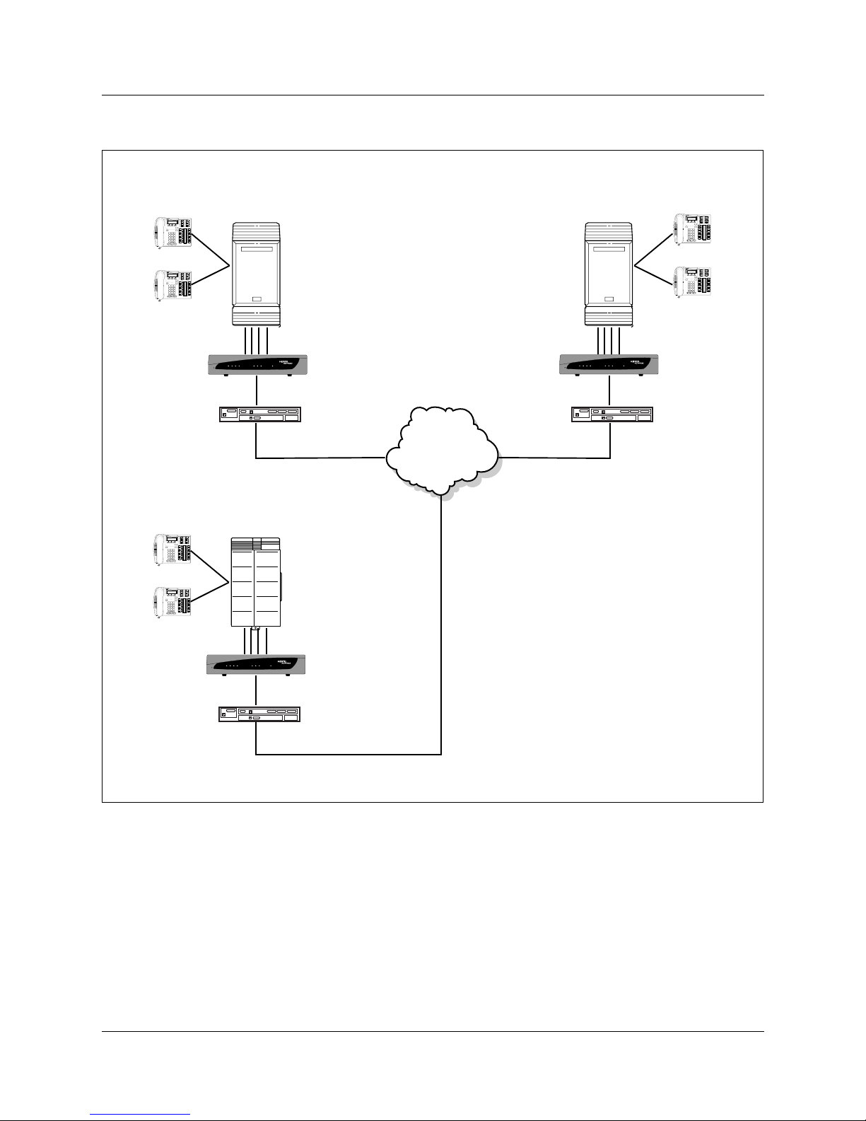
The layout diagram, Figure 2 on page 18, illustrates a typical VoIP Gateway application.
Figure 1 Norstar VoIP Gateway front panel
1 2 3 4
C h a n n e l s
Data
Control
LAN
Ready
VoIP Gateway
Norstar VoIP Gateway Configuration Guide
Page 18
18
Figure 2 Typical VoIP Gateway application
VoIP Gateway
Router
Branch Office
Modular ICS
l
y
d
tro
a
t
a
n
N
a
e
o
A
1 2 3 4
C h a n n e l s
R
D
L
C
VoIP Gateway
Branch Office
Compact ICS
Internet
Head Office
Modular ICS
l
y
d
tro
ta
a
n
N
a
e
o
1 2 3 4
C h a n n e l s
R
D
LA
C
VoIP Gateway
VoIP Gateway
Router
VoIP Gateway
1 2 3 4
C h a n n e l s
R
D
LA
C
VoIP Gateway
l
y
o
d
tr
ta
a
n
N
a
e
o
Router
VoIP Gateway key features
• high quality voice, data and fax over IP networks
• supports up to 4 analog telephone loop start ports
• connected to the IP network via a 10/100 Base-T Ethernet interface
• codecs include: G.711, G.723.1, G.729A
• T.38 Fax with superior performance (can handle a round trip delay up to 9 sec.)
• compliant with H.323 (Version 4)
P0606298 02
Page 19

19
• Emergency Line, connected to the unused pins on port #4, with a relay to an analog line, even
if the VoIP Gateway is powered off.
• LEDs on the front and rear panels that provide information on the operating status of the VoIP
Gateway and the network interface
• Restart button on the front panel that restarts the VoIP Gateway
• compact, rugged enclosure only one-half of a 19-inch rack unit, 1 U high (1.75" or 44.5 mm)
• mounting option of installing two VoIP Gateway in a single 19-inch rack shelf, one U high
(1.75" or 44.5 mm).
Supported H.323 features
The VoIP Gateway implements the RadVision™ H.323 version 4.0 protocol stack. In this version,
the VoIP Gateway features the following:
Gatekeeper
• Works without a Gatekeeper using the internal phone table.
• Registers to a known Gatekeeper.
• Supports Gatekeeper registration with prefixes
• Functions as an H.323 gateway or can imitate an H.323 terminal with up to four aliases.
• Uses routed-mode calls.
• Uses direct-mode calls.
• Uses redundant Gatekeepers if a redundant Gatekeeper is defined.
• Can fallback to internal routing table if there is no communication with the Gatekeeper.
• Supports the "TimeToLive" parameter. The VoIP Gateway sends Registration requests up to
"TimeToLive" expiration.
• Supports IRR messages for KeepAlive.
• Supports the mapping of destination (Alias) numbers in the ACF message by the Gatekeeper.
• Supports RAI (Resource Available Indication) messages, informing gatekeeper that the
gateway resources are below a threshold.
Call setup
• Can use the Normal Connect procedure.
• Can use the Fast Connect procedure with or without immediately opening a H.245 channel.
• Can use Tunneling.
• Can negotiate a codec from a list of given codecs for Normal or Fast Connect procedures.
• Can open a H.245 channel when using Fast Connect.
Norstar VoIP Gateway Configuration Guide
Page 20

20
Other:
• Supports using a Country Code (0xB5) and Manufacturers Code (0x28) in H.323 messages
• Supports H.323 Annex D, T.38 real time FAX.
• Supports H.450 Call Hold, Call Transfer and Call Forwarding supplementary services
(H.450.1, H.450.2, H.450.3 and H.450.4).
• Supports the following codecs: G.711 A-law, G.711 µ-law, G.723.1 (6.3 kbps, 5.3 kbps), G.729.
• Supports DTMF and HookFlash signal out of band using the H.245 channel (using the
"Alphanumeric" field).
• Supports DTMF out of band using H.225/Q.931 keypad facility messages.
• Supports of one or two stage dialing for network to VoIP Gateway calls.
• Supports reopening of logical channel and implementation of empty terminal capability set.
• Supports configurable H.323 Port Range.
• Supports H.225/Q.931 Progress Indicator parameter for Fast Connect, enabling playing of
local ringback tone or to cut through the voice channel to listen to remote call progress tones/
messages.
P0606298 02
Page 21

Chapter 2
IP Telephony overview
This section provides a brief overview of the “Key IP telephony concepts”. It also provides a
“Prerequisites checklist” to help you set up your IP Telephony network.
Key IP telephony concepts
In traditional telephony, the voice path between two telephones is circuit switched. This means that
the analog or digital connection between the two telephones is dedicated to the call. The voice
quality is usually excellent, since there is no other signal to interfere.
In IP telephony, the VoIP Gateway encodes the speech of the call into small data packets called
frames. The system sends the frames across the IP network to the other VoIP Gateway, where the
frames are decoded and sent to the receiving telephone. If some of the frames get lost while in
transit, or are delayed too long, the receiving telephone experiences poor voice quality. On a
properly-configured network, voice quality should be consistent for all IP calls.
21
The following sections describe some of the components for IP telephony:
• “VoIP trunks” on page 21
• “Gatekeepers” on page 22
• “Codecs” on page 22
• “Jitter Buffer” on page 23
• “QoS routing” on page 24
VoIP trunks
VoIP trunks allow voice signals to travel across IP networks. The VoIP Gateway converts the voice
signal into IP packets, which are then transmitted through the IP network to a gateway on the
remote system. The device at the other end reassembles the packets into a voice signal. Business
Communications Manager and Meridian 1 IPT are devices that can use the H.323 protocol trunks
which the VoIP Gateway supports.
VoIP trunks and analog/digital telephones
While analog and digital telephones cannot be connected to the VoIP Gateway system with an IP
connection, they can make and receive calls to and from other systems through VoIP trunks. Calls
received through the VoIP trunks to system telephones are received through the LAN or WAN and
are translated within the VoIP Gateway to voice channels.
Norstar VoIP Gateway Configuration Guide
Page 22
22 Key IP telephony concepts
Gatekeepers
A gatekeeper tracks IP addresses of specified devices, and provides authorization for making and
accepting calls for these devices. A gatekeeper is not required as part of the network to which your
VoIP Gateway is attached, but Gatekeepers can be useful on networks with a large number of
devices.
Note: The VoIP Gateway does not contain a gatekeeper application. If you want to put a
gatekeeper on your network, it must be put on a separate gatekeeper server. The VoIP
Gateway is compatible with RadVision and CSE 1000 gatekeepers.
Codecs
The algorithm used to compress and decompress voice is embedded in a software entity called a
codec (COde-DECode).
Two popular Codecs are G.711 and G.729. The G.711 Codec samples voice at 64 kilobits per
second (kbps) while G.729 samples at a far lower rate of 8 kbps. For actual bandwidth
requirements, refer to “Determining the bandwidth requirements” on page 153, where you will
note that the actual kbps requirements are slightly higher than the label suggests.
Voice quality is better when using a G.711 CODEC, but more network bandwidth is used to
exchange the voice frames between the telephones.
If you experience poor voice quality, and suspect it is due to heavy network traffic, you can get
better voice quality by configuring the IP telephone to use a G.729 CODEC.
The VoIP Gateway supports these codecs:
•G.729
•G.723
•G.711-uLaw
•G.711-aLaw
P0606298 02
Page 23

Key IP telephony concepts 23
Jitter Buffer
Voice frames are transmitted at a fixed rate, because the time interval between frames is constant.
If the frames arrive at the other end at the same rate, voice quality is perceived as good. In many
cases, however, some frames can arrive slightly faster or slower than the other frames. This is
called jitter, and degrades the perceived voice quality. To minimize this problem, the VoIP
Gateway uses a jitter buffer for arriving frames.
The Norstar VoIP Gateway uses a dynamic jitter buffer that can be configured using two
parameters:
• Minimum delay (0 msec to 150 msec).
This defines the starting jitter capacity of the buffer. For instance, at 0 msec, there is no
buffering at the start. At the default level of 70 msec, the VoIP Gateway will always buffer
incoming packets by at least 70 msec worth of voice frames.
• Optimization Factor (0 to 12).
This defines how the jitter buffer tracks to changing network conditions. When set at its
maximum value of 12, the dynamic buffer will aggressively track changes in delay (based on
packet loss statistics) to increase the size of the buffer and then not decay back down. This
results in the best packet error performance, but at the cost of extra delay. At the minimum
value of 0, the buffer tracks delays only to compensate for clock drift and quickly will decay
back to the minimum level. This optimizes the delay performance but at the expense of a
higher error rate.
The default settings of 70 msec Minimum delay and 7 Optimization Factor should provide a good
compromise between delay and error rate. The jitter buffer "holds" incoming packets for 70 msec
before making them available to the codec for decoding into voice. The codec actually "takes"
frames from the buffer at regular intervals in order to produce continuous speech. As long as
delays in the network do not change (jitter) by more than 70 msec from one packet to the next,
there will always be a sample in the buffer for the codec to use. If there is more than 70 msec of
delay at any time during the call, the packet is too late. The codec will try to access a frame and
will not be able to find one. The codec must produce a voice sample even if a frame is not
available. It will actually create a voice sample to use that minimizes the effect of the loss. This
loss is then flagged as the buffer being too small. The dynamic algorithm then causes the size of
the buffer to increase for the next voice session. The size of the buffer may decrease again if the
gateway notices that the buffer is not filling up as much as expected. At no time will the buffer
shrink to less than the minimum size configured in the Minimum delay parameter.
This delaying of packets can provide somewhat of a communications challenge, as speech is
delayed by the number of frames in the buffer. For one-sided conversations, there are no issues.
However, for two-sided conversations, where one party tries to interrupt the other speaking party,
it can be annoying. In this second situation, by the time the voice of the interrupter reaches the
interruptee, the interruptee has spoken (2*jitter size) frames past the intended point of interruption.
Norstar VoIP Gateway Configuration Guide
Page 24

24 Prerequisites checklist
QoS routing
To minimize voice jitter over low bandwidth connections, the VoIP Gateway can assign specific
DiffServ Marking in the IPv4 header of the IP telephony data packets.
The DiffServ Code point (DSCP) is contained in the second byte of the IPv4 header. DSCP is used
by the router to determine how the packets will be separated for Per Hop Behavior (PHB). The
DSCP is contained within the DiffServ field, which was known as the ToS field in older versions.
Prerequisites checklist
Before you set up VoIP trunks on the VoIP Gateway, complete the following checklists to ensure
that the system is correctly set up. Some questions do not apply to all installations.
This guide contains a number of appendices that explain various aspects of the system directly
related to IP telephony functions.
This section includes the following checklists:
• “Network diagram” on page 24
• “Network devices” on page 25
• “Network assessment” on page 25
Network diagram
To aid in installation, a Network Diagram is needed to provide a basic understanding of how the
network is configured. Before you install IP functionality, you must have a network diagram that
captures all of the information described in the following table.
Table 1 Network diagram prerequisites
Prerequisites Yes
1.a Has a network diagram been developed?
1.b Does the network diagram contain any routers, switches or bridges with corresponding
IP addresses and bandwidth values for WAN or LAN links?
1.c Does the network diagram contain IP Addresses, netmasks, and network locations of all Norstar VoIP
Gateways?
1.d Does the network diagram contain IP Addresses and netmasks of any other IP Telephony gateways
that you need to connect to?
1.e Does the network diagram contain the IP address for any Gatekeeper that may be used?
P0606298 02
Page 25

Network assessment 25
Network devices
The following table contains questions about devices on the network such as firewalls, NAT
devices, and DHCP servers.
• If the network uses public IP addresses, complete 2.c.
• If the network uses private IP addresses, complete 2.d. to 2.e.
Table 2 Network device checklist
Prerequisites Yes No
2.a Is the network using DHCP?
2.b Is the network using private IP addresses?
2.c Do you have a public IP addresses for the Norstar VoIP Gateway?
2.d Does the system have a firewall/NAT device?
2.e A hub-based core will not have suitable performance for IP Telephony. Does the network
use a non-hub solution at its core?
Network assessment
The following table of questions are meant to ensure that the network is capable of handling IP
telephony, and that existing network services are not adversely affected.
Table 3 Network assessment
Prerequisites Yes No
3.a Has a network assessment been completed?
3.b Has the number of switch/hub ports available and used in the LAN infrastructure been
calculated?
3.c Does the switch use VLANs? If so, get the VLAN port number and ID.
3.d Have the used and available IP addresses for each LAN segment been calculated?
3.e Has DHCP usage and location been recorded?
3.f Has the speed and configuration of the LAN been calculated?
3.g Has the estimated latency values between network locations been calculated?
3.h Have the Bandwidth/CIR utilization values for all WAN links been calculated?
3.i Has the quality of service availability on the network been calculated?
Norstar VoIP Gateway Configuration Guide
Page 26

26 Network assessment
P0606298 02
Page 27

Chapter 3
Configuring the VoIP Gateway
The VoIP Gateway has a web interface you use for gateway configuration, including downloading
of configuration files and for run-time monitoring. You can access the web interface from any
standard web browser, such as Microsoft™ Internet Explorer or Netscape™ Navigator.
Specifically, you can employ this facility to set up the gateway configuration parameters needed to
configure the VoIP Gateway. You also have the option to reset the gateway to apply the new set of
parameters.
Computer requirements
To use the web interface, you need the following:
• a computer capable of running your web browser
• a network connection to the VoIP Gateway
• one of the following compatible web browsers
• Microsoft™ Internet Explorer™ (version 5.0 and higher)
• Netscape™ Navigator™ (version 7.0 and higher)
27
Accessing the web interface
To access the web interface:
1 Open your web browser.
2 In the URL field, enter the IP address of the VoIP Gateway.
When you enter the IP address make sure you include http:// at the start of the IP address (for
example: http://10.1.10.10.
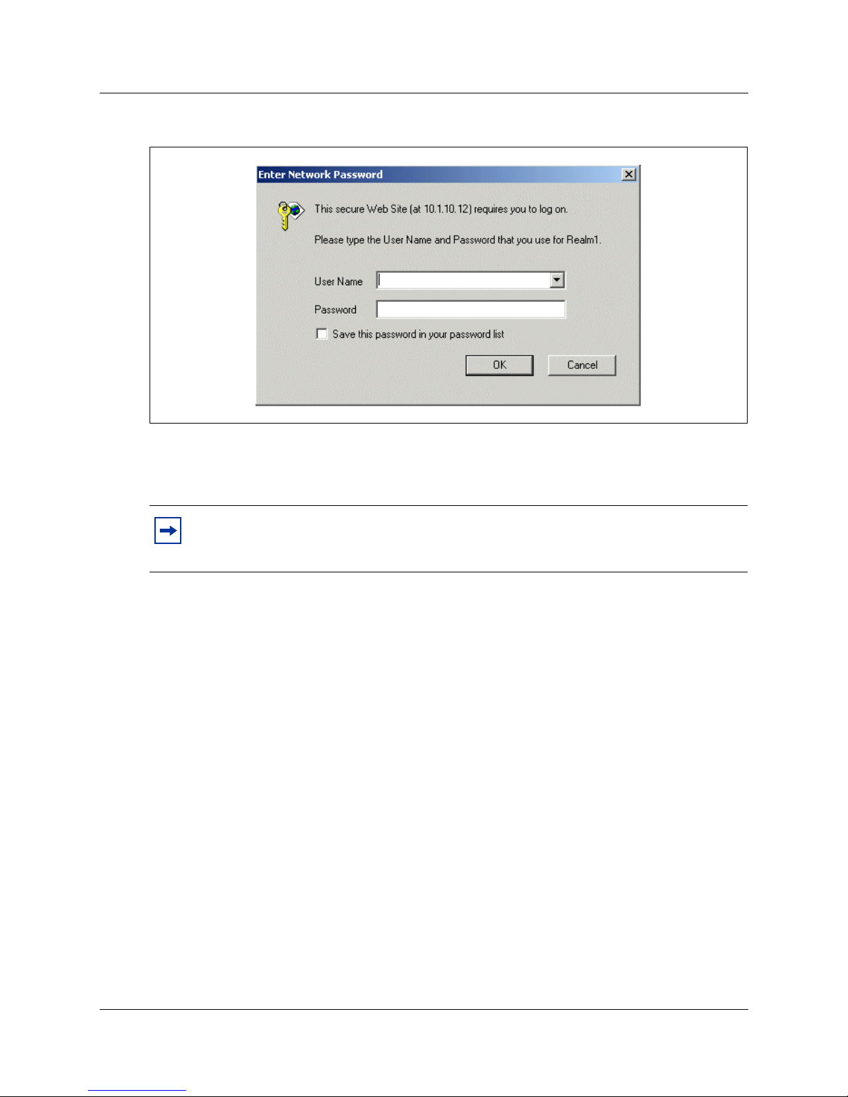
The Enter Network Password screen appears.
Norstar VoIP Gateway Configuration Guide
Page 28
28 Accessing the web interface
Figure 3 Web browser login screen
3 Enter the User Name and Password.
If you have not changed the user name and password, the default User Name is Admin and the
default password is Admin.
Note: Nortel Networks recommends that you change the User Name and Password from
their default values. For information about how to change the User Name and Password,
refer to “Changing the VoIP Gateway password” on page 133.
4 Click the OK button.
P0606298 02
Page 29
Configuring the Protocol Definition parameters 29
Configuring the Protocol Definition parameters
To configure the Protocol Definition parameters:
1 Access the web interface.
2 Click the Protocol Management button.
3 Click the Protocol Definition tab.
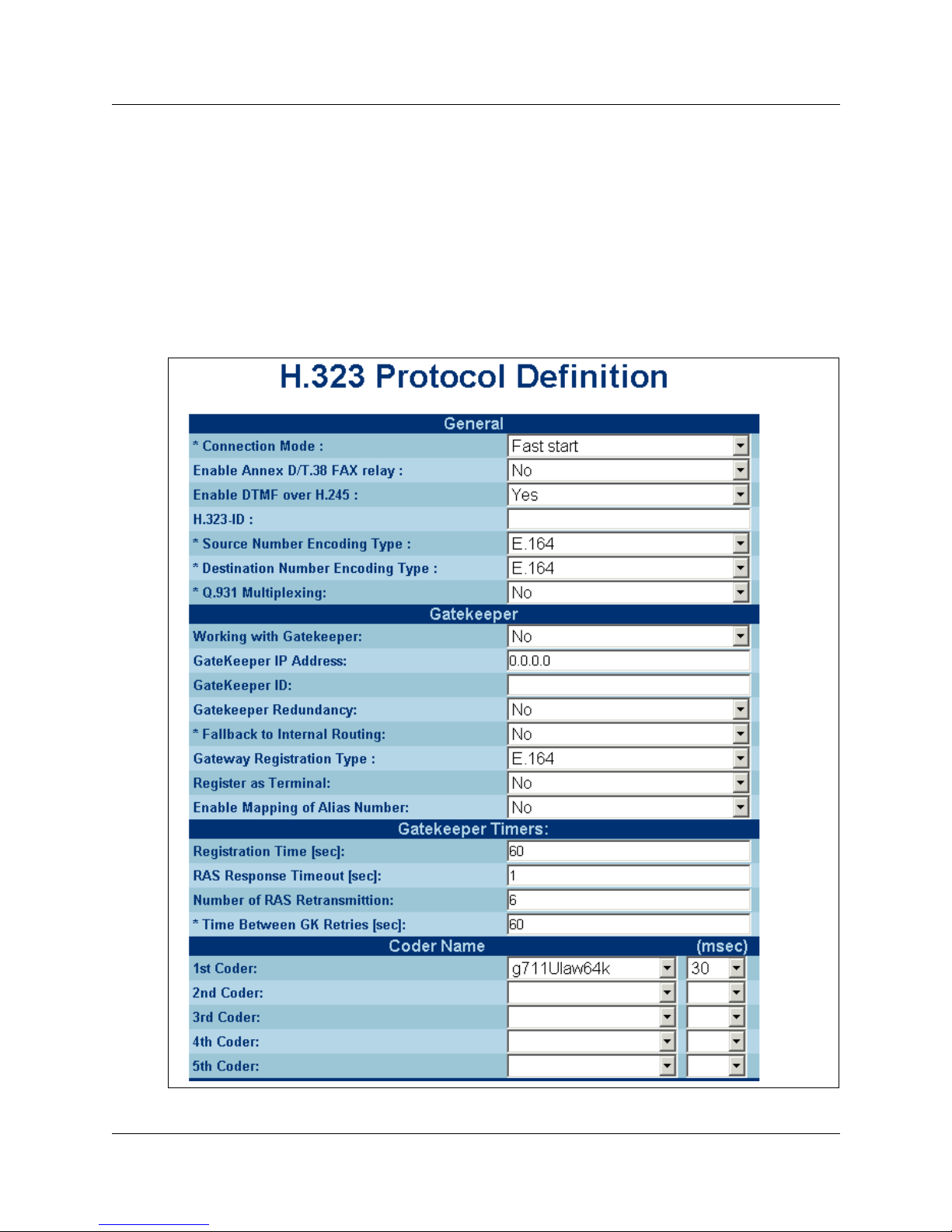
The Protocol Definition screen appears.
Figure 4 Protocol Definition screen
Norstar VoIP Gateway Configuration Guide
Page 30

30 Configuring the Protocol Definition parameters
4 Configure the Protocol Definition parameters according to the following table.
Table 4 Protocol Definition parameters
Parameter Description
General
Connection Mode Select Fast Start if you want the VoIP Gateway to use the Fast Start connection mode.
Select Normal if you want the VoIP Gateway to use the Normal connection mode.
The default value is Fast Start.
The Fast Start connection mode allows a media path to be established using H.225,
without having to start the full H.245 protocol session. In some situations, you need to use
fast start in order to control call progress tones.
Enable Annex D/T.38 Fax
relay
Enable DTMF over H.245 Select Yes to enable DTMF over H.245.
H.323-ID Enter the VoIP Gateway H.323-ID you want to use for registration to the Gatekeeper.
Source Number
Encoding Type
Destination Number
Encoding Type
Select No to disable Annex D/T.38 Fax relay.
Select Yes to enable Annex D/T.38 Fax relay.
When you enable this feature, the VoIP Gateway can send and receive Fax messages
using the H.323 Annex D T.38 procedure.
When you enable this feature, the VoIP Gateway sends out of band DTMF signaling using
H.245. Out of band signaling is recommended for use with H.323 protocol and the Norstar
KSU.
You can enter a string up to 19 characters long.
When you are using a Gatekeeper, the VoIP Gateway will send a registration message to
the Gatekeeper with this H323-ID string.
Select the source number encoding type. This defines the encoding type of the calling
phone number in H.225 setup messages.
You can select E.164, H.323-ID, E.164 & H.323-ID, TableValues or TableValues &
H.323-ID.
Select TableValues if you want the VoIP Gateway to use the values configured in the
Tel -> IP Source Number Manipulation table.
Select H323-ID if you want the VoIP Gateway to add the H323-ID to the source
information.
Select E.164 if you want the VoIP Gateway to use E.164 source encoding and not use the
encoding type defined in the table.
The default value is E.164.
Note: If you select an option that includes “H.323-ID”, you must enter a string in the
H.323-ID box.
Select the destination number encoding type. This defines the encoding type of the called
phone number in H.225 setup messages.
You can select E.164, H.323-ID, E.164 and H.323-ID, or TableValues.
Select TableValues if you want the VoIP Gateway to use the values configured in the
Tel -> IP Dest Number manipulation table.
Select H.323-ID if you want the VoIP Gateway to add the H323-ID to the destination
information.
Select E.164 if you want the VoIP Gateway to use E.164 destination encoding and not use
the encoding type defined in the table.
The default value is E.164.
Note: If you select an option that includes “H.323-ID”, you must enter a string in the
H.323-ID box.
P0606298 02
Page 31

Configuring the Protocol Definition parameters 31
Table 4 Protocol Definition parameters (Continued)
Parameter Description
Q.931 Multiplexing Select No to disable H.323 Q.931 multiplexing.
Select Yes to enable H.323 Q.931 multiplexing.
The default value is No.
When you enable Q.931 multiplexing, the VoIP Gateway uses the same socket for all
H.225 messages sent to the same destination.
Gatekeeper
Working with Gatekeeper Select Yes if you are using a Gatekeeper to determine what IP address should be used
Gatekeeper IP address Enter the IP address of the Gatekeeper you are using.
Gatekeeper ID Enter the string used to identify the Gatekeeper.
Gatekeeper Redundancy Select No if you are using a single Gatekeeper.
First Redundant
Gatekeeper
Second Redundant
Gatekeeper
Fallback to internal
routing
for the telephone number dialed.
Select No if you are not using a Gatekeeper to resolve telephone number to IP address
translation. If you are not using a Gatekeeper, you must configure the Telephone to IP
Routing table on the VoIP Gateway.
Enter the IP address in dotted format notation, for example 192.10.1.255.
Select Yes if you are using two or three Gatekeepers.
If you enable Gatekeeper Redundancy, the VoIP Gateway can work with multiple
Gatekeepers. If there is no response from the current Gatekeeper, the VoIP Gateway tries
to communicate with the other Gatekeepers. When a new Gatekeeper is found, the VoIP
Gateway continues working with it until the next failure.
To use Gatekeeper Redundancy, you must enter an IP address in the First Redundant
Gatekeeper box. If you are using three Gatekeepers, you also need to enter an IP
address in the Second Redundant Gatekeeper box.
Enter the IP address of the first redundant Gatekeeper you are using.
Enter the IP address in dotted format notation, for example 192.10.1.255.
Note: This parameter is available only if you select Yes in the Gatekeeper Redundancy
box.
Enter the IP address of the second redundant Gatekeeper you are using.
Enter the IP address in dotted format notation, for example 192.10.1.255.
Note: This parameter is available only if you select Yes in the Gatekeeper Redundancy
box.
Select No if you do not want to use the internal Telephone to IP Routing table when the
Gatekeeper is not available.
Select Yes if you want to use the internal Telephone to IP Routing table when the
Gatekeeper is not available.
When the VoIP Gateway falls back to the internal Telephone to IP Routing table, the VoIP
Gateway continues scanning for the Gatekeeper. When the VoIP Gateway finds an active
Gatekeeper, it switches from internal routing back to Gatekeeper routing.
The default value is No.
Norstar VoIP Gateway Configuration Guide
Page 32

32 Configuring the Protocol Definition parameters
Table 4 Protocol Definition parameters (Continued)
Parameter Description
Gateway Registration
Ty pe
Register as Terminal Select No if you want the VoIP Gateway to register and act as a standard gateway.
Enable Mapping of Alias
Number
Gatekeeper Timers
Registration Time Enter the time in seconds between registrations to the Gatekeeper.
RAS Response Timeout Enter the time in seconds that the VoIP Gateway waits for a RAS response from the
Number of RAS
retransmission
Time between GK retries Enter the time in seconds before the VoIP Gateway tries to contact the list of Gatekeepers
Select the registration type you want to use. This defines the encoding type of the VoIP
Gateways phone numbers that is used when the VoIP Gateway registers these numbers
with a Gatekeeper.
You can select E.164, H.323-ID, E.164 & H.323-ID, TableValues, or TableValues &
H.323-ID.
Select TableValues if you want the VoIP Gateway to use the values configured in the
Gateway Registration Prefixes Table.
Select H323-ID if you want the VoIP Gateway to add the H323-ID to the destination
information.
Select E.164 if you want the VoIP Gateway to use E.164 encoding and not use the
encoding type defined in the table.
The default value is E.164.
Note: If you have entered a string in the H.323 ID box, this string is added to the gateway
registration when you select H.323-ID, E.164 & H.323-ID, or TableValues & H.323-ID.
Select Yes if you want the VoIP Gateway to register and act as an H.323 terminal with
multiple aliases (up to 4). Also, in all gateway messages, the terminal type value is set to
terminal.
The default value is No.
Select Yes to allow the Gatekeeper to change the gateway destination number using the
Alias parameter in the ACF message.
Select No if you do not want the Gatekeeper to change the gateway destination number.
The default Registration Time is 60 seconds.
Note: This setting must match the configuration settings on your Gatekeeper.
Gatekeeper. When this time expires, the VoIP Gateway retransmits the RAS message.
The default time is 2 seconds.
Note: This setting must match the configuration settings on your Gatekeeper.
Enter the number of times that the VoIP Gateway retransmits the RAS message to the
Gatekeeper, before the VoIP Gateway decides that the Gatekeeper is not responding.
If you have enabled Gatekeeper Redundancy, the VoIP Gateway will then try the next
Gatekeeper.
If none of the Gatekeepers are responding and you have enabled Fallback to internal
routing, the VoIP Gateway will start using the internal Telephone to IP Routing table.
The default number of retransmissions is 2.
Note: This setting must match the configuration settings on your Gatekeeper.
again.
The default time is 60 seconds.
Note: This setting must match the configuration settings on your Gatekeeper.
P0606298 02
Page 33

Configuring the Protocol Definition parameters 33
Table 4 Protocol Definition parameters (Continued)
Parameter Description
Coders
1st Coder Select the first preferred codec for the VoIP Gateway.
This codec is the highest priority codec and is used by the VoIP Gateway whenever
possible.
Select the size of the Voice Packet used with this codec in milliseconds.
Selecting the size of the packet determines how many codec payloads are combined into
one RTP (Voice) packet.
2nd Coder Select the second preferred codec for the VoIP Gateway.
If the far end gateway cannot use the codec assigned as the 1st Coder, the VoIP Gateway
attempts to use this codec.
Select the size of the Voice Packet used with this codec in milliseconds.
Selecting the size of the packet determines how many codec payloads are combined into
one RTP (Voice) packet.
3rd Coder Select the third preferred codec for the VoIP Gateway.
If the far end gateway cannot use the codecs assigned as the 1st Coder or 2nd Coder, the
VoIP Gateway attempts to use this codec.
Select the size of the Voice Packet used with this codec in milliseconds.
Selecting the size of the packet determines how many codec payloads are combined into
one RTP (Voice) packet.
4th Coder Select the fourth preferred codec for the VoIP Gateway.
If the far end gateway cannot use the codecs assigned as the 1st Coder, 2nd Coder or
3rd Coder, the VoIP Gateway attempts to use this codec.
Select the size of the Voice Packet used with this codec in milliseconds.
Selecting the size of the packet determines how many codec payloads are combined into
one RTP (Voice) packet.
5th Coder Select the fifth preferred codec for the VoIP Gateway.
If the far end gateway cannot use the codecs assigned as the 1st Coder, 2nd Coder,
3rd Coder or 4th Coder, the VoIP Gateway attempts to use this codec.
If the far end gateway cannot use any of these five codecs, a VoIP connection cannot be
made.
Select the size of the Voice Packet used with this codec in milliseconds.
Selecting the size of the packet determines how many codec payloads are combined into
one RTP (Voice) packet.
DTMF and Dialing Parameters
Enable Automatic Dialing Select Yes to enable Automatic Dialing.
Select No to disable Automatic Dialing.
When you enable Automatic Dialing, a telephone number is automatically dialed as soon
you select one of the VoIP Gateway lines. To use the Automatic Dialing feature, you must
configure the Automatic Dialing Table. For information about how to configure the
Automatic Dialing Table, refer to “Configuring the Automatic Dialing phone numbers” on
page 61.
When you disable Automatic Dialing, you hear dial tone when you select one of the VoIP
Gateway lines. You can then dial the telephone number of the person you want to call.
Recommendations:
We recommend that you select No to disable Automatic Dialing.
Norstar VoIP Gateway Configuration Guide
Page 34

34 Configuring the Protocol Definition parameters
Table 4 Protocol Definition parameters (Continued)
Parameter Description
Max Digits in Phone
Number
Interdigits Timeout Enter the time in seconds that the VoIP Gateway waits between digits dialed by the user.
Use ‘#’, “*’ digits for
dialing
Dial Tone Duration Enter the time in seconds that the dial tone is played.
Fast Start Parameters
Open H.245 channel Select No if you do not want the VoIP Gateway to open an H.245 channel when making a
Play Ringback Tone to IP Select Dont Play if you do not want the Ringback tone played to IP side of the call.
Enter the maximum number of digits that can be dialed.
You can enter a value from 2 to 19.
The default value is 4.
Note: Dialing ends when the maximum number of digits are dialed, the Interdigits Timeout
expires, or the '#' key is dialed.
When the Interdigits Timeout expires, the VoIP Gateway will attempt to dial the digits
already received.
You can enter a value of 0 to 5 seconds.
The default value is 4 seconds.
Select No if you do not want to allow the "*" and "#" to be used for telephone numbers
dialed by a user or entered for the endpoint telephone numbers.
Select Yes if you want to allow the "*" and "#" to be used for telephone numbers dialed by
a user or entered for the endpoint telephone number.
The default value is No.
Note: When this feature is activated, the # can not be used to end the dialed number.
Note: The # and * can always be used as first digit of a dialed number, even if you select
No for this parameter.
The default time is 16 seconds.
Note: Dial Tone Duration is not applicable when Automatic Dialing is enabled.
Fast Start connection.
Select Yes if you want the VoIP Gateway to open an H.245 channel immediately after the
Fast Start connection is established. The opening of an H.245 channel may be needed for
relaying DTMF digits over H.245 channel during a call.
The default value is No.
Recommendations:
For quicker call setup when you are using Fast Start, set this parameter to Yes.
Select Play if you want the Ringback tone played to the IP side of the call. When you
select Play, the Progress Indicator is set to 8 in the H.225 Alert message (PI=8).
The default value is Play.
Note: If you are using Auto Answer lines on the Norstar KSU and digit delivery to
automatically ring a destination Norstar set, select Dont Play for this parameter.
Recommendations:
If the destination lines on the Norstar KSU are configured as manual answer, set this
parameter to Play.
If the destination lines on the Norstar KSU are configured as auto answer, set this
parameter to Dont Play.
When you select Dont Play the Norstar KSU provides ringback tone.
P0606298 02
Page 35

Table 4 Protocol Definition parameters (Continued)
Parameter Description
Configuring the Protocol Definition parameters 35
Play Ringback Tone to Tel Select Dont Play if you do not want to play the Ringback Tone to the Telephone side of
Progress Indicator to
ISDN
Progress Indicator to IP Select 0 if you do not want to set the Progress Indicator (PI) in the H.225 Alert messages
Send Media Information
in Connect
the call.
Select Play if you want to play the Ringback Tone to the Telephone side of the call.
Select Play according to PI if want to play the Ringback Tone to the Telephone side of
the call when indicated by the Progress Indicator. When you select this option, the
Ringback Tone is played when the Progress Indicator is set to PI=1 or PI=8 in the
received H.225 Alert message. (default)
The default value is Dont Play.
Recommendations:
If there are any Business Communications Manager or Meridian 1 IPT gateways on your
VoIP network, set this parameter to Dont Play.
Select 0 if you do not want to set the Progress Indicator (PI) in the H.225 Alert messages
sent to an ISDN endpoint.
Select 1 if you want to set the Progress Indicator to PI = 1 in H.225 Alert messages sent.
Select 8 if you want to set the Progress Indicator to PI = 8 in H.225 Alert messages sent.
Select Not configured if you want to set the Progress Indicator in the H.225 Alert
messages according to "Play Ringback Tone to IP" parameter.
The default value is Not Configured.
Recommendations:
If there are any Business Communications Manager or Meridian 1 IPT gateways on your
VoIP network, set this parameter to Not configured.
sent to an IP telephony endpoint.
Select 1 if you want to set the Progress Indicator to PI = 1 in H.225 Alert messages sent.
Select 8 if you want to set the Progress Indicator to PI = 8 in H.225 Alert messages sent.
Select Not configured if you want to set the Progress Indicator in the H.225 Alert
messages according to "Play Ringback Tone to IP" parameter.
The default value is Not Configured.
Recommendations:
If there are any Business Communications Manager or Meridian 1 IPT gateways on your
VoIP network, set this parameter to Not configured.
Select No to send the Fast Start Structure response in the Alert message. This provides
the media path used when the destination endpoint is providing the Ringback Tones.
Select Yes to send the Fast Start Structure response after the call is answered and the
connect message is sent.
After receiving the Fast Start Setup message, the gateway should reply with an H.225
message that includes media information structure. The gateway can send the message
with Alert or Connect messages. Sending this information in Alert message enables the
remote side to open the voice channel before receiving the Connect message.
The default value is No.
Note: This option is only relevant if Fast Start is used.
Recommendations:
If there are any Business Communications Manager or Meridian 1 IPT gateways on your
VoIP network, set this parameter to No.
Norstar VoIP Gateway Configuration Guide
Page 36

36 Configuring the Protocol Definition parameters
Table 4 Protocol Definition parameters (Continued)
Parameter Description
Open Media On Connect Select No to open the voice channel after sending an Alert message.
Select Yes to open the voice channel after the call is answered and a Connect message is
sent.
The default value is No.
Note: This option is only relevant if you use Fast Start or Tunneling.
Recommendations:
If there are any Business Communications Manager or Meridian 1 IPT gateways on your
VoIP network, set this parameter to No.
Number Manipulation and Routing Modes
Add Trunk Group ID as
Prefix
IP to Tel Routing Mode Select Route calls before manipulation if you want to route the calls before the number
Tel to IP Routing Mode Select Route calls before manipulation if you want to route the calls before the number
H450 Supplementary Services
Select No if you do not want the VoIP Gateway to add the Trunk Group ID
Select Yes if you want to add the Hunt Group ID as a prefix to the destination phone
number for incoming calls. This option can be used to define various routing rules.
To use this feature you must configure the Hunt Group IDs.
Recommendations:
We recommend you set this parameter to No.
manipulation rules are applied.
Select Route calls after manipulation if you want to route the calls after the number
manipulation rules are applied.
The option is not applicable if you use a Gatekeeper.
The default is Route calls before manipulation.
Recommendations:
We recommend you set this parameter to Route calls before manipulation.
manipulation rules are applied.
Select Route calls after manipulation if you want to route the calls after the number
manipulation rules are applied.
The option is not applicable if you use a Gatekeeper.
The default is Route calls before manipulation.
Recommendations:
We recommend you set this parameter to Route calls before manipulation.
Enable Hold Select No to disable Hold service.
Select Yes to enable Hold service (H.450.4).
If the Hold service is enabled, a user can activate Hold (or unhold) using the HookFlash.
On receiving a Hold request, the remote party will be put on hold and hear the hold tone.
The default is No.
Note: To use the H.450 Supplementary Services, the gateways at both ends must support
these services.
Recommendations:
The Business Communications Manager and Meridian 1 IPT gateways do not support
H.450 Supplementary Services. If there are any Business Communications Manager or
Meridian 1 IPT gateways on your VoIP network, set this parameter to No.
P0606298 02
Page 37

Configuring the Protocol Definition parameters 37
Table 4 Protocol Definition parameters (Continued)
Parameter Description
Enable Transfer Select No to disable Call Transfer service.
Select Yes to enable Call Transfer service (H.450.2).
If the Transfer service is enabled, the user can activate Transfer using HookFlash
signaling. If this service is enabled, the remote party will perform the call transfer.
The default is No.
Note: To use the H.450 Supplementary Services, the gateways at both ends must support
these services.
Recommendations:
The Business Communications Manager and Meridian 1 IPT gateways do not support
H.450 Supplementary Services. If there are any Business Communications Manager or
Meridian 1 IPT gateways on your VoIP network, set this parameter to No.
Enable Forward Select No to disable the Call Forward service.
Select Yes to enable Call Forward service (H.450.3).
A Call Forward table must be defined to use the Call Forward service.
The default is No.
Note: To use the H.450 Supplementary Services, the gateways at both ends must support
these services.
Recommendations:
The Business Communications Manager and Meridian 1 IPT gateways do not support
H.450 Supplementary Services. If there are any Business Communications Manager or
Meridian 1 IPT gateways on your VoIP network, set this parameter to No.
Misc parameters
IP Security Select No if you want the VoIP Gateway to accept all H.323 calls that are sent to the VoIP
Gateway.(default)
Select Yes if you want the VoIP Gateway to accept H.323 calls only from IP addresses
defined in Prefix routing table. The VoIP Gateway rejects all calls from unknown IP
addresses.
When you are using a Gatekeeper, Nortel Networks recommends you set this option to
Yes. This allows the Gatekeeper to decide if H.323 calls are accepted or rejected.
The default value is No.
Norstar VoIP Gateway Configuration Guide
Page 38

38 Configuring the Protocol Definition parameters
Table 4 Protocol Definition parameters (Continued)
Parameter Description
Channel Select Mode Select By Phone Number if you want the VoIP Gateway to select the channel according
Enable Caller ID Select Yes for this option.
Caller ID Type Select Bellcore for this option.
Polarity Reversal Select No if you do not want the VoIP Gateway to change the line polarity.
Enable Current
Disconnect
Enable Hook-Flash Select No to disable Hook-Flash.
Send DTMF over H225/
Q.931
to the destination telephone number received in H.225 setup message. This telephone
number is the number you enter in the Phone Number box on the Channels - Hunt Group
screen.
If you are using Hunt Groups, select one of the following four options.
•Select Cyclic Ascending if you want the VoIP Gateway to always select the next
higher channel number in the Hunt Group. When the VoIP Gateway reaches the
highest channel number in the Hunt Group, it will select the lowest channel number in
the Hunt Group and then start ascending again.
•Select Ascending Always if you want the VoIP Gateway to always start at the lowest
channel number in the Hunt Group and if that channel is not available, select the next
higher channel.
•Select Cyclic Descending if you want the VoIP Gateway to always select the next
lower channel number in the Hunt Group. When the VoIP Gateway reaches the lowest
channel number in the Hunt Group, it will select the highest channel number in the
Hunt Group and then start descending again.
•Select Descending Always if you want the VoIP Gateway to always start at the
highest channel number in the Hunt Group and if that channel is not available, select
the next lower channel.
For information about how to enter the Phone Number and Hunt Group ID, refer to
“Configuring the Channels to Hunt Group parameters” on page 58.
Note: To prevent conflicts, configure the Norstar Hunt Group to start its hunt from the
opposite end of the channel numbers. For example, if the VoIP Gateway starts the hunt
from the lowest channel number, ensure the Norstar starts its hunt from the highest
channel number.
When you select Yes, the Calling number and Display text is sent to the Norstar KSU
between first and second rings.
Bellcore is the Caller ID Type that is compatible with the Norstar KSU.
Select Yes if you want the VoIP Gateway to change the line polarity on call answer and
change it back on call release.
The default value is No.
Recommendations:
For use with the Norstar KSU, you must set this parameter to No.
Select Yes to generate a Current disconnect pulse of 900msec after a call is released
from IP.
Recommendations:
For use with the Norstar KSU, you must set this parameter to Yes.
Select Yes if you want the VoIP Gateway to send an H.245 User Input Indication message
when a hookflash is detected.
The default is No.
Select No for this option.
The Norstar VoIP Gateway uses H.245 to send DTMF out of band (refer to the Enable
DTMF over H.245 option).
P0606298 02
Page 39

Table 4 Protocol Definition parameters (Continued)
Parameter Description
Configuring the Protocol Definition parameters 39
Release Call on “Setup
Ack”
Does Setup Include
Phone Number?
Default Destination
Number
Number of Max Calls Enter the maximum number of calls that the VoIP Gateway can have active at the same
H323 Base Port Enter the starting TCP/UDP transport port for H.225/H.245 messages. The VoIP Gateway
H225 Listen Port Enter the port number on which the VoIP Gateway expects to receive H.225/Setup
H225 Dial Port Enter the port number on which the VoIP Gateway sends H.225/Setup messages.
Enable SysLog CDR Select No if you do not want to send Call Detail Recording (CDR) information to the
Select No if you do not want the VoIP Gateway to release the call when it receives a
Setup Ack message.
Select Yes if you want the VoIP Gateway to release the call when it receives a Setup Ack
message.
Use this option to enable receiving Setup Ack messages, when the Enable DTMF overlap
Dialing option is disabled.
The default is No.
Select No if you want the VoIP Gateway to send an empty SETUP (or Gatekeeper ARQ)
message. An empty SETUP message does not include the called party number.
Select Yes if you want the VoIP Gateway to include the called party number in the SETUP
message.
The default is Yes.
Recommendations:
Select Yes for this parameter.
Enter the telephone number that the VoIP Gateway dials if a call setup is received with no
telephone number.
The number you enter must be one of the End Points Phone Numbers you have defined.
time.
If you enter 0, there is no restriction on the maximum number of calls.
The default value is 0.
will use dynamic ports (except RTP ports) starting from this port to this port +500.
If you enter 0, the default ports are used.
The default port range is 32000 to 65000.
Note: You normally do not have to change the base port number unless you are using the
VoIP Gateway behind NAT. Nortel Networks does not recommend using the VoIP
Gateway behind NAT.
messages.
The default port number is 1720.
Note: You normally do not have to change the base port number unless you are using the
VoIP Gateway behind NAT. Nortel Networks does not recommend using the VoIP
Gateway behind NAT.
The default port number is 1720.
Note: You normally do not have to change the base port number unless you are using the
VoIP Gateway behind NAT. Nortel Networks does not recommend using the VoIP
Gateway behind NAT.
SysLog server.
Select Yes if you want to sent CDR information to the Syslog server at end of each Call.
The default is No.
5 Click the Submit button to save your changes.
6 To apply the changes, you must reset the VoIP Gateway. To reset the VoIP Gateway:
Norstar VoIP Gateway Configuration Guide
Page 40

40 Configuring the Protocol Definition parameters
a Click the Reset button.
b Click the Restart button.
A confirmation dialog box appears.
c Click the OK button.
7 To save the changes so they are available after a power fail, you must save the changes to
non-volatile memory. To save the changes to non-volatile memory:
a Click the Save Configuration button.
The Save Configuration to the system screen appears.
b Click the Save Configuration button that is in middle of the screen.
A confirmation message appears when the save is complete.
Note: The Save Configuration option is useful for trying out a new configuration.
Simply make the change and try out the new configuration. If you are happy with the
new configuration, save the changes to non-volatile memory. If you are not happy
with the new configuration, do not save the changes to non-volatile memory and
remove power from the VoIP Gateway. The VoIP Gateway will return to the previous
configuration.
P0606298 02
Page 41

Configuring the Registration Prefixes
The Gatekeeper Registration Prefix Table allows you to associate dialing plan information with
specific digit prefixes.
Gatekeepers can route calls based on two pieces of information: destination digits and numbering
plan. The ability to route by numbering plan is useful when Gatekeepers must route both private
and public calls. For example, company A has an internal private network with private access
codes. These codes are 7 digit numbers comprising a location code and an internal DN. A code of
395-3491 also looks like a valid local public number. The numbering plan information allows the
Gatekeeper to route the apparently ambiguous destination digits that could be dialed on both a
private and public network. For example, a digit string of 395-3491 with a numbering plan of
E.164 Public / National is routed to the destination IP address of a gateway that interfaces with the
PSTN. The same digit string with a numbering plan of Private / Level1 Regional is routed to the IP
address of a gateway on the private network.
The Gatekeeper Registration Prefix Table data is sent when the gateway requests permission to
register with the Gatekeeper. This registration request is triggered by a gateway reset.
If there are no entries in the Registration Prefix Table, then the VoIP Gateway registers with the
Gatekeeper using the numbers defined on the Channels - Hunt Group screen and the NPI / TON
selected in the Gateway Registration Type parameter on the Protocol Definition screen.
Configuring the Registration Prefixes 41
Using a Radvision ECS 3.0 Gatekeeper
The Norstar VoIP Gateway works with the Radvision ECS 3.0 Gatekeeper. The Radvision
Gatekeeper uses both the destination digits and the numbering plan information (NPI/TON) to
resolve a called number into an IP address for the destination. If you are using a Radvision
Gatekeeper, we recommend that you configure the Registration Prefix Table to guarantee
maximum flexibility.
Using a Nortel Networks CSE1000 Gatekeeper
The Norstar VoIP Gateway works with the Nortel Networks CSE1000 Gatekeeper. The CSE1000
Gatekeeper is manually administered to set up its dialing plan and does not require the use of the
Gatekeeper Registration Prefixes Table.
The CSE1000 Gatekeeper is setup based on the H323-ID. The H323-ID is a unique text string used
to represent the gateway. When using the CSE1000 Gatekeeper, select H323-ID as the Gateway
Registration Type.
To configure the Gatekeeper Registration Prefixes parameters:
1 Access the web interface.
2 Click the Protocol Management button.
Norstar VoIP Gateway Configuration Guide
Page 42

42 Configuring the Registration Prefixes
3 Click the Registration Prefixes tab.
The Registration Prefixes Table screen appears.
Figure 5 Registration Prefixes Table screen
P0606298 02
Page 43

Configuring the Registration Prefixes 43
4 Configure the Registration Prefixes according to the following table.
Table 5 Registration Prefixes Table
Parameter Description
GK Registration Prefixes Enter the Gatekeeper Registration prefix. These prefixes are used by the VoIP Gateway to
register to a Gatekeeper.
When entering a prefix, you can create an entry that represents multiple prefixes using
the following notation:
• [n-m] represents a range of numbers. For example, enter [250-279] to specify all
prefixes from 250 to 279.
Type of Number Select the H.225/Q.931 Number Type assigned to this entry.
You can select Unknown, Private or E.164 Public.
The default is Unknown.
Select the H.225/Q.931 Number Plan assigned to this entry.
• If you selected Unknown as the Number Type, you can select Unknown.
• If you selected Private as the Number Type, you can select Unknown, Level 0
Regional (Local), Level 1 Regional, Level 2 Regional or PISN Specific.
• If you selected E.164 Private as the Number Type, you can select Unknown,
International, National, Network Specific, Subscriber or Abbreviated.
The default is Unknown.
If you are using a RadVision Gatekeeper, you must configure the Type of Number fields.
If you are using a CSE1k Gatekeeper, you are not required to configure the Type of
Number fields.
Note: The Type of Number information is used only for registration of this number where
the VoIP Gateway is the destination endpoint. The Type of Number encoding used when
dialing from this VoIP Gateway is set in the number manipulation tables for Telephone to
IP calls.
See Appendix A, “Numbering and Dial Plans,” on page 147, for more information about
the Type of Number fields.
5 Click the Submit button to save your changes.
6 To save the changes so they are available after a power fail, you must save the changes to
non-volatile memory. To save the changes to non-volatile memory:
a Click the Save Configuration button.
The Save Configuration to the system screen appears.
b Click the Save Configuration button that is in middle of the screen.
A confirmation message appears when the save is complete.
Note: The Save Configuration option is useful for trying out a new configuration.
Simply make the change and try out the new configuration. If you are happy with the
new configuration, save the changes to non-volatile memory. If you are not happy
with the new configuration, do not save the changes to non-volatile memory and
remove power from the VoIP Gateway. The VoIP Gateway will return to the previous
configuration.
Norstar VoIP Gateway Configuration Guide
Page 44

44 Configuring the Number Manipulation tables
Configuring the Number Manipulation tables
The VoIP Gateway provides Number Manipulation tables for incoming and outgoing calls. These
tables are used to modify the destination and source telephone numbers so that the calls can be
routed properly.
The VoIP Gateway has four number Manipulation tables.
• “Configuring number manipulation for Destination Phone Numbers for Norstar to IP calls” on
page 46
• “Configuring number manipulation for Digit Delivery” on page 49
• “Configuring number manipulation for Source Phone Numbers for IP to Norstar calls” on
page 52
• “Configuring number manipulation for Source Phone Numbers for Norstar to IP calls” on
page 55
Note: Number manipulation can occur either before or after a routing decision is made.
To control when number manipulation is done, set the IP to Tel Routing Mode and the
Tel to IP Routing Mode parameters. For information about these parameters, refer the
description of these parameters on Table 4 on page 30.
Number Manipulation overview
The Norstar VoIP Gateway contains a number of very powerful and useful utilities for the
manipulation of source and destination telephone numbers used on a call by call basis.
Understanding how the manipulation works and what circumstances would need digit
manipulation is key to setting up the overall network dialing plan.
Basic Concepts
The VoIP Gateway uses four manipulation tables:
• IP -> Tel Source Numbers
• Tel -> IP Source Numbers
• Tel -> IP Destination Numbers
• Digit Delivery (IP -> Tel Destination Numbers)
In addition, similar tables are used for routing decisions in the VoIP Gateway:
• Tel -> IP Routing table
• IP -> Hunt Group Routing table.
These routing tables do not use any manipulation features but simply allow calls to be directed
properly, as determined by the dialed digits.
Each of these will be explained further in sections to follow. Each manipulation table utilizes the
same basic set of rules.
P0606298 02
Page 45

Configuring the Number Manipulation tables 45
Digit parsing
In order to determine whether or not a particular call requires digit manipulation or routing, the
number (source or destination) is parsed to see if it matches the digit rule in the table (Dialed
number, Source Number, Prefix). Digit parsing options include:
• Digits: Numerals from 0 – 9.
• Wild card: * means any number of digits of any type
• Don’t Care: X means any single digit of any type
• Terminator: # indicates the end of the digit string (no digits follow)
• Range: [x - y] indicates the range of numbers from x to y inclusive
• Range: [x,y,z] indicates the value may be any of the indicate list
For example:
• [5551200 – 5551300] represents all of the numbers from 5551200 to 5551300 inclusive.
• [3,4,5]xxx# would be a 4 digit number beginning in either 3, 4 or 5.
• 123[100 -200]* would be numbers that start with 123100 to 123200 inclusive.
Number Classification – NPI / TON
In the tables that provide manipulation from Tel -> IP, you may specify the NPI / TON to be used
in the H.323 message coding. This classification is important in some gatekeepers (Radvision) in
order to provide address resolution. The NPI / TON used in your setup message must be the same
as that used in registration by the destination gateway.
NPI / TON is a term originally used with Q.931 which is the basis for H.323. Choices for
Numbering Plan Indicator (NPI) are:
• Unknown
•Private
• Public (e164)
Public is chosen if the number is part of the PSTN numbering plan that is used for national dialing.
Private is used to represent a numbering plan that is used in a private voice network.
For more information on Numbering and Dial Plans, refer to Appendix A, “Numbering and Dial
Plans,” on page 147.
Stripping and adding digits
The tables provide the ability to strip leading digits from the digit string (number of stripped digits)
and to add new leading digits (prefix to add).
Norstar VoIP Gateway Configuration Guide
Page 46

46 Configuring the Number Manipulation tables
Configuring number manipulation for Destination Phone Numbers
for Norstar to IP calls
This number manipulation table is used to manipulate the digits that are dialed into the VoIP
Gateway prior to setting up the call. Numbers that are dialed by the user are first checked in this
table to see if there is a match. If there is a match, the values entered into the table are used to
manipulate the digits. This is programmed in "Protocol Management / Protocol Definition" by
changing the setting for "Tel to IP Routing Mode". This manipulation can be done either before or
after a routing decision is made for the call. In general, a routing decision will be made before
manipulation.
Uses for manipulation can be as follows:
• To strip dialing plan digits from the number. For example, a user might dial 6 in front of each
number in order to indicate a private network number. If this leading digit is not removed by
Norstar routing, it may be removed here before the call is setup. This would allow the
destination number to be understood by a gatekeeper or by the destination gateway (for
routing to the correct output hunt group).
• Assignment of NPI / TON. The VoIP Gateway can use a single global setting for NPI / TON
classification or it can use the setting in this table on a call by call basis. Control for this is
done using “Protocol Management / Protocol Definition / Destination Number Encoding
Type”
To configure the Destination Phone Number Manipulation Table for TEL->IP calls:
1 Access the web interface.
2 Click the Protocol Management button.
3 Point to the Manipulation Tables tab and click the Tel -> IP Dest Numbers link.
The
Destination Phone Number Manipulation Table for TEL->IP calls screen appears.
P0606298 02
Page 47

Configuring the Number Manipulation tables 47
Figure 6 Destination Phone Number Manipulation Table for TEL->IP calls screen
4 To configure the first ten entries, click the Table Index drop list and click 1-10.
To configure the last ten entries, click the Table Index drop list and click 11-20.
Norstar VoIP Gateway Configuration Guide
Page 48

48 Configuring the Number Manipulation tables
5 Configure the Phone Number Manipulation Table according to the following table.
Table 6 Destination Phone Number Manipulation Table for TEL->IP calls (Norstar to IP)
Parameter Description
Dialed Number Enter the number you want to match for this table entry.
When entering a number, you can create an entry that represents multiple numbers using
the following notation:
• [n-m] represents a range of numbers
• [n,m] represents multiple numbers
• x represents any single digit
• * represents any digit or multiple digits
• # represents the end of a number
• For example:
[5551200-5551300] represents all of the numbers from 5551200 to 5551300
[2221,2231,2241] represents the numbers 2221, 2231 and 2241
54324* represents any number that starts with 54324
54324xx represents a 7 digit number that starts with 54324
123[100-200]* represents numbers that starts with 123100 to numbers that start with
123200.
When the dialed number matches the number you enter here, the rules in this number
manipulation table entry are applied.
The VoIP Gateway matches the rules starting at the top of the table. For this reason, enter
more specific rules above more generic rules. For example, if you enter 551* in entry 1
and 55* in entry 2, the VoIP Gateway applies rule 1 to numbers that starts with 551 and
applies rule 2 to numbers that start with 550, 552, 553, 554, 555, 556, 557, 558 and 559.
However if you enter 55* in entry 1 and 551* in entry 2, the VoIP Gateway applies rule 1 to
all numbers that start with 55 including numbers that start with 551.
Num of stripped digits Enter the number of digits that you want to remove from the destination phone number.
For example, if you enter 3 and the destination phone number is 5551234, the new
destination phone number is 1234.
Prefix to add Enter the number you want to add to the front of the stripped destination phone number.
For example, if you enter 9 and the stripped destination phone number is 1234, the new
destination phone number is 91234.
Type of Number Select the H.225/Q.931 Number Type assigned to this entry.
You can select Unknown, Private or E.164 Public.
The default is Unknown.
Select the H.225/Q.931 Number Plan assigned to this entry.
• If you selected Unknown as the Number Type, you can select Unknown.
• If you selected Private as the Number Type, you can select Unknown, Level 0
Regional (Local), Level 1 Regional, Level 2 Regional or PISN Specific.
• If you selected E.164 Private as the Number Type, you can select Unknown,
International, National, Network Specific, Subscriber or Abbreviated.
The default is Unknown.
If you are using a RadVision Gatekeeper, you must configure the Type of Number fields.
If you are using a CSE1k Gatekeeper, you are not required to configure the Type of
Number fields.
See Appendix A, “Numbering and Dial Plans,” on page 147, for more information about
the Type of Number fields.
6 Click the Submit button to save your changes.
P0606298 02
Page 49

Configuring the Number Manipulation tables 49
7 To save the changes so they are available after a power fail, you must save the changes to
non-volatile memory. To save the changes to non-volatile memory:
a Click the Save Configuration button.
The Save Configuration to the system screen appears.
b Click the Save Configuration button that is in middle of the screen.
A confirmation message appears when the save is complete.
Note: The Save Configuration option is useful for trying out a new configuration.
Simply make the change and try out the new configuration. If you are happy with the
new configuration, save the changes to non-volatile memory. If you are not happy
with the new configuration, do not save the changes to non-volatile memory and
remove power from the VoIP Gateway. The VoIP Gateway will return to the previous
configuration.
Configuring number manipulation for Digit Delivery
This number manipulation table defines the rules for changing the destination number received for
an incoming IP to Norstar call.
Digit delivery is a method used to automatically dial through to a target DN on the destination
Norstar system. You can configure the Norstar system to automatically answer certain lines. In this
configuration, the Norstar system provides a dial tone and waits for the caller to dial further digits,
as if they were a set on that system. These extra digits may be for a local telephone set or a local
PSTN call. If the destination digits received by the VoIP Gateway match a row of this table, the
digits will first be manipulated according to the rule in that row. They will then be dialed out after
the Norstar system answers the line. If a call does not match a row of this table, it is still connected
according to the IP to Hunt Group Routing Table. However, the Norstar system will not dial out
digits when the line is answered.
Note: The Digit Delivery Table feature uses auto answer trunks to implement dialing
through to the destination target line. In order to use the Digit Delivery Table feature,
DTMF tone receivers must be available on the target Norstar system. DTMF receivers are
provided with a Services Card, Combo Card or E&M trunk card.
To configure the number manipulation for Digit Delivery:
1 Access the web interface.
2 Click the Protocol Management button.
3 Point to the Manipulation Tables tab and click the Digit Delivery Table link.
The
Digit Delivery Table screen appears.
Norstar VoIP Gateway Configuration Guide
Page 50

50 Configuring the Number Manipulation tables
Figure 7 Digit Delivery Table screen
4 To configure the first ten entries, click the Table Index drop list and click 1-10.
To configure the last ten entries, click the Table Index drop list and click 11-20.
P0606298 02
Page 51

Configuring the Number Manipulation tables 51
5 Configure the Digit Delivery Table according to the following table.
Table 7 Digit Delivery Table
Parameter Description
Called Number Enter the number you want to match for this table entry.
When entering a number, you can create an entry that represents multiple numbers using
the following notation:
• [n-m] represents a range of numbers
• [n,m] represents multiple numbers
• x represents any single digit
• * represents any digit or multiple digits
• # represents the end of a number
• For example:
[5551200-5551300] represents all of the numbers from 5551200 to 5551300
[2221,2231,2241] represents the numbers 2221, 2231 and 2241
54324* represents any number that starts with 54324
54324xx represents a 7 digit number that starts with 54324
123[100-200]* represents numbers that starts with 123100 to numbers that start with
123200.
When the dialed number matches the number you enter here, the rules in this number
manipulation table entry are applied.
The VoIP Gateway matches the rules starting at the top of the table. For this reason, enter
more specific rules above more generic rules. For example, if you enter 551* in entry 1
and 55* in entry 2, the VoIP Gateway applies rule 1 to numbers that starts with 551 and
applies rule 2 to numbers that start with 550, 552, 553, 554, 555, 556, 557, 558 and 559.
However if you enter 55* in entry 1 and 551* in entry 2, the VoIP Gateway applies rule 1 to
all numbers that start with 55 including numbers that start with 551.
Num of stripped digits Enter the number of digits that you want to remove from the destination phone number.
For example, if you enter 3 and the destination phone number is 5551234, the new
destination phone number is 1234.
Prefix to add Enter the number you want to add to the front of the stripped source phone number.
For example, if you enter 9 and the stripped source phone number is 1234, the new
source phone number is 91234.
The prefix can include digit and the following:
• D = wait for dial tone
You should always use D as the first prefix digit so that the VoIP Gateway will wait for a
Norstar dial tone before dialing out the digits. Dial tone detection can only be used as
the first prefix digit.
• P = pause
You can use the pause to wait for any secondary dial tone. This might be required for
dialing out through the Norstar to the PSTN. The pause waits for 1.5 seconds. Longer
periods may be achieved by using more than one P character. For example, PP will
wait for 3.0 seconds.
• other digits such as destination codes to access outside lines
Note: The wait for dial tone character is case sensitive. You must use a capital D to
indicate wait for dial tone.
6 Click the Submit button to save your changes.
7 To save the changes so they are available after a power fail, you must save the changes to
non-volatile memory. To save the changes to non-volatile memory:
Norstar VoIP Gateway Configuration Guide
Page 52

52 Configuring the Number Manipulation tables
a Click the Save Configuration button.
The Save Configuration to the system screen appears.
b Click the Save Configuration button that is in middle of the screen.
A confirmation message appears when the save is complete.
Note: The Save Configuration option is useful for trying out a new configuration.
Simply make the change and try out the new configuration. If you are happy with the
new configuration, save the changes to non-volatile memory. If you are not happy
with the new configuration, do not save the changes to non-volatile memory and
remove power from the VoIP Gateway. The VoIP Gateway will return to the previous
configuration.
Configuring number manipulation for Source Phone Numbers for IP
to Norstar calls
This number manipulation table defines the rules for changing the source number received in IP to
Norstar calls. A common use of this table is to alter the Calling Line Identification information that
is presented on the destination Norstar telephone.
To configure the number manipulation for Source Phone Numbers for IP to Norstar calls:
1 Access the web interface.
2 Click the Protocol Management button.
3 Point to the Manipulation Tables tab and click the IP -> Tel Source Numbers link.
Source Phone Number Manipulation Table for IP->TEL calls screen appears.
The
P0606298 02
Page 53

Configuring the Number Manipulation tables 53
Figure 8 Source Phone Number Manipulation Table for IP->TEL calls screen
Norstar VoIP Gateway Configuration Guide
Page 54

54 Configuring the Number Manipulation tables
4 Configure the Phone Number Manipulation Table according to the following table.
Table 8 Source Phone Number Manipulation Table for IP->TEL calls (IP to Norstar)
Parameter Description
Prefix Enter the number you want to match for this table entry.
When entering a number, you can create an entry that represents multiple numbers using
the following notation:
• [n-m] represents a range of numbers
• [n,m] represents multiple numbers
• x represents any single digit
• * represents any digit or multiple digits
• # represents the end of a number
• For example:
[5551200-5551300] represents all of the numbers from 5551200 to 5551300
[2221,2231,2241] represents the numbers 2221, 2231 and 2241
54324* represents any number that starts with 54324
54324xx represents a 7 digit number that starts with 54324
123[100-200]* represents numbers that starts with 123100 to numbers that start with
123200.
When the dialed number matches the number you enter here, the rules in this number
manipulation table entry are applied.
The VoIP Gateway matches the rules starting at the top of the table. For this reason, enter
more specific rules above more generic rules. For example, if you enter 551* in entry 1
and 55* in entry 2, the VoIP Gateway applies rule 1 to numbers that starts with 551 and
applies rule 2 to numbers that start with 550, 552, 553, 554, 555, 556, 557, 558 and 559.
However if you enter 55* in entry 1 and 551* in entry 2, the VoIP Gateway applies rule 1 to
all numbers that start with 55 including numbers that start with 551.
Num of stripped digits Enter the number of digits that you want to remove from the source phone number.
For example, if you enter 3 and the source phone number is 5551234, the new source
phone number is 1234.
Prefix to add Enter the number you want to add to the front of the stripped destination phone number.
For example, if you enter 9 and the stripped destination phone number is 1234, the new
destination phone number is 91234.
5 Click the Submit button to save your changes.
6 To save the changes so they are available after a power fail, you must save the changes to
non-volatile memory. To save the changes to non-volatile memory:
a Click the Save Configuration button.
The Save Configuration to the system screen appears.
P0606298 02
Page 55

Configuring the Number Manipulation tables 55
b Click the Save Configuration button that is in middle of the screen.
A confirmation message appears when the save is complete.
Note: The Save Configuration option is useful for trying out a new configuration.
Simply make the change and try out the new configuration. If you are happy with the
new configuration, save the changes to non-volatile memory. If you are not happy
with the new configuration, do not save the changes to non-volatile memory and
remove power from the VoIP Gateway. The VoIP Gateway will return to the previous
configuration.
Configuring number manipulation for Source Phone Numbers for
Norstar to IP calls
This number manipulation table is used to manipulate or assign NPI / TON values to the source
number used for the call setup. Generally speaking, this table is not used since the source phone
number is a statically set parameter for the VoIP Gateway.
Source phone numbers are entered into the VoIP Gateway in the Channels – Hunt Group table. In
that table, a phone number can be entered for each port of the VoIP Gateway. This number may be
different from port to port, which is appropriate for a system that uses a key system style of line
appearances, or could be the same, which is appropriate for a system that uses the PBX system of
line pools.
The source number in an H.323 message is used to identify the caller for use in calling line ID
presentation. As such, manipulation of the source digits would normally only need to be done in
order to change the digits so that they will be in a more appropriate form for calling line ID.
For example, the VoIP Gateway may be setup so that it reflects the telephone number used in the
private dialing plan. Source manipulation can then be used to transform that private number into a
public dialing plan number that represents the normal PSTN number that would be used to dial the
location.
The source manipulation table may also be used to assign a specific NPI / TON classification to
the calling number. Setting an NPI / TON can be done globally or values used in this table can be
applied. Control for this is done using “Protocol Management / Protocol Definition / Source
Number Encoding Type”
To configure the
1 Access the web interface.
2 Click the Protocol Management button.
3 Point to the Manipulation Tables tab and click the Tel -> IP Source Numbers link.
The Source Phone Number Manipulation Table for TEL->IP calls screen appears.
Source Phone Number Manipulation Table for TEL->IP calls:
Norstar VoIP Gateway Configuration Guide
Page 56

56 Configuring the Number Manipulation tables
Figure 9 Source Phone Number Manipulation Table for TEL->IP calls screen
4 To configure the first ten entries, click the Table Index drop list and click 1-10.
To configure the last ten entries, click the Table Index drop list and click 11-20.
5 Configure the Phone Number Manipulation Table according to the following table.
Table 9 Source Phone Number Manipulation Table for TEL->IP calls (Norstar to IP)
Parameter Description
Prefix Enter the number you want to match for this table entry.
When entering a number, you can create an entry that represents multiple numbers using
the following notation:
• [n-m] represents a range of numbers
• [n,m] represents multiple numbers
• x represents any single digit
• * represents any digit or multiple digits
• # represents the end of a number
• For example:
[5551200-5551300] represents all of the numbers from 5551200 to 5551300
[2221,2231,2241] represents the numbers 2221, 2231 and 2241
54324* represents any number that starts with 54324
54324xx represents a 7 digit number that starts with 54324
123[100-200]* represents numbers that starts with 123100 to numbers that start with
123200.
When the dialed number matches the number you enter here, the rules in this number
manipulation table entry are applied.
The VoIP Gateway matches the rules starting at the top of the table. For this reason, enter
more specific rules above more generic rules. For example, if you enter 551* in entry 1
and 55* in entry 2, the VoIP Gateway applies rule 1 to numbers that starts with 551 and
applies rule 2 to numbers that start with 550, 552, 553, 554, 555, 556, 557, 558 and 559.
However if you enter 55* in entry 1 and 551* in entry 2, the VoIP Gateway applies rule 1 to
all numbers that start with 55 including numbers that start with 551.
P0606298 02
Page 57

Configuring the Number Manipulation tables 57
Table 9 Source Phone Number Manipulation Table for TEL->IP calls (Norstar to IP) (Continued)
Parameter Description
Num of stripped digits Enter the number of digits that you want to remove from the source phone number.
For example, if you enter 3 and the source phone number is 5551234, the new source
phone number is 1234.
Type of Number Select the H.225/Q.931 Number Type assigned to this entry.
You can select Unknown, Private or E.164 Public.
The default is Unknown.
Select the H.225/Q.931 Number Plan assigned to this entry.
• If you selected Unknown as the Number Type, you can select Unknown.
• If you selected Private as the Number Type, you can select Unknown, Level 0
Regional (Local), Level 1 Regional, Level 2 Regional or PISN Specific.
• If you selected E.164 Private as the Number Type, you can select Unknown,
International, National, Network Specific, Subscriber or Abbreviated.
The default is Unknown.
If you are using a RadVision Gatekeeper, you must configure the Type of Number fields.
If you are using a CSE1k Gatekeeper, you are not required to configure the Type of
Number fields.
See Appendix A, “Numbering and Dial Plans,” on page 147, for more information about
the Type of Number fields.
6 Click the Submit button to save your changes.
7 To save the changes so they are available after a power fail, you must save the changes to
non-volatile memory. To save the changes to non-volatile memory:
a Click the Save Configuration button.
The Save Configuration to the system screen appears.
b Click the Save Configuration button that is in middle of the screen.
A confirmation message appears when the save is complete.
Note: The Save Configuration option is useful for trying out a new configuration.
Simply make the change and try out the new configuration. If you are happy with the
new configuration, save the changes to non-volatile memory. If you are not happy
with the new configuration, do not save the changes to non-volatile memory and
remove power from the VoIP Gateway. The VoIP Gateway will return to the previous
configuration.
Norstar VoIP Gateway Configuration Guide
Page 58

58 Configuring the Channels to Hunt Group parameters
Configuring the Channels to Hunt Group parameters
From the Channels - Hunt Group screen you can enable and assign telephone numbers to the VoIP
Gateway ports.
To configure the Channels to Hunt Group parameters:
1 Access the web interface.
2 Click the Protocol Management button.
3 Click the Channels - Hunt Group link.
The Channels - Hunt Group screen appears.
Figure 10 End Point’s Phone Number table
P0606298 02
Page 59

4 Configure the End Point’s Phone Numbers according to the following table.
You must enter a number in the Phone Number boxes for each port that you want to use.
Table 10 End Point’s Phone Numbers
Parameter Description
Configuring the Channels to Hunt Group parameters 59
Channel(s) The numbers in the Channel(s) boxes represent the ports on the back of the VoIP
Phone Number In each of the Phone Number boxes, enter the telephone number that is assigned to that
Hunt Group Id In each of the Hunt Group Id boxes, enter the Hunt Group ID assigned to the channel. The
Gateway.
To enable a VoIP Gateway channel, you must enter the port number on this screen.
channel.
You must enter a telephone number for a channel to enable that channel.
If you want to disable a port, leave the Phone Number box for that channel blank.
The Phone Number you enter is the “source” number in the protocol. Also, if you are not
using the Digit Manipulation tables, the Phone Number you enter on this screen is
presented as the Calling Line Identification information on the destination set.
Recommendations:
If the analog loop start lines are configured as one dedicated line per Norstar set, enter a
unique phone number for each channel.
If the analog loop start lines are configured in a line pool, enter the same phone number
for all of the channels. The phone number you enter would typically be the main number
required to reach a receptionist.
If you assign unique phone numbers to channels configured in a line pool, the calling line
identification information would become confusing, since many Norstar sets may have
access to the same channel.
same Hunt Group ID can be used for more than one channel.
The Hunt Group ID is an optional field that is used to define a group of channels that are
used for routing IP to telephone calls. If an incoming call is assigned to a Hunt Group, the
call is routed to the channel or channels that correspond to the Hunt Group ID enter here.
In most situations, the application will need all 4 channels assigned to one hunt group.
Important: If you enter a Hunt Group Id, you must configure the IP to Hunt Group Routing
Table. If you do not configure the IP to Hunt Group Routing Table, calls will not complete.
For information about how to configure this table, refer to “Configuring the IP to Hunt
Group Routing” on page 67.
Note: Only the entries for the first four channels are supported on the VoIP Gateway.
5 Click the Submit button to save your changes.
6 To apply the changes, you must reset the VoIP Gateway. To reset the VoIP Gateway:
a Click the Reset button.
b Click the Restart button.
A confirmation dialog box appears.
c Click the OK button.
7 To save the changes so they are available after a power fail, you must save the changes to
non-volatile memory. To save the changes to non-volatile memory:
Norstar VoIP Gateway Configuration Guide
Page 60

60 Configuring the Channels to Hunt Group parameters
a Click the Save Configuration button.
The Save Configuration to the system screen appears.
b Click the Save Configuration button that is in middle of the screen.
A confirmation message appears when the save is complete.
Note: The Save Configuration option is useful for trying out a new configuration.
Simply make the change and try out the new configuration. If you are happy with the
new configuration, save the changes to non-volatile memory. If you are not happy
with the new configuration, do not save the changes to non-volatile memory and
remove power from the VoIP Gateway. The VoIP Gateway will return to the previous
configuration.
P0606298 02
Page 61

Configuring the Automatic Dialing phone numbers 61
Configuring the Automatic Dialing phone numbers
The Automatic Dialing Table defines the telephone numbers that are automatically dialed when
this port is used. This table is used only if Automatic Dialing feature is enabled.
To configure the Automatic Dialing Table:
1 Access the web interface.
2 Click the Protocol Management button.
3 Click the Automatic Dialing tab.
The Automatic Dialing Table screen appears.
Figure 11 Automatic Dialing Table
4 In the Destination Phone Number box for a port, enter the telephone number to dial.
When this VoIP Gateway port is selected when making a call, the number in the Destination
Phone Number box is automatically dialed.
If you do not want to use this port for Automatic Dialing, leave the Destination Phone
Number box blank.
5 Repeat step 4 for each port you want to use for Automatic Dialing.
6 Click the Submit button to save your changes.
7 To save the changes so they are available after a power fail, you must save the changes to
non-volatile memory. To save the changes to non-volatile memory:
a Click the Save Configuration button.
The Save Configuration to the system screen appears.
Norstar VoIP Gateway Configuration Guide
Page 62

62 Configuring the Automatic Dialing phone numbers
b Click the Save Configuration button that is in middle of the screen.
A confirmation message appears when the save is complete.
Note: The Save Configuration option is useful for trying out a new configuration.
Simply make the change and try out the new configuration. If you are happy with the
new configuration, save the changes to non-volatile memory. If you are not happy
with the new configuration, do not save the changes to non-volatile memory and
remove power from the VoIP Gateway. The VoIP Gateway will return to the previous
configuration.
P0606298 02
Page 63

Configuring the Caller ID Display
The Caller ID Display Table contains the Caller ID information that is sent when a call is made
using the VoIP Gateway. The person receiving the call can use this information for caller
identification. The information on this table is sent in the H.225 Setup message sent to the remote
party.
To configure the Caller ID Display Table:
1 Access the web interface.
2 Click the Protocol Management button.
3 Click the Caller ID tab.
The Caller Display Info screen appears.
Figure 12 Caller Display Info
Configuring the Caller ID Display 63
4 In the Caller ID/Name box, enter the Caller ID string that sent when a call is made using this
VoIP Gateway port.
The caller ID string can contain up to 18 characters, but Nortel Networks recommends that
you do not exceed 16 characters to ensure proper display on Norstar telephones.
5 Repeat step 4 for each VoIP Gateway port.
6 Click the Submit button to save your changes.
7 To save the changes so they are available after a power fail, you must save the changes to
non-volatile memory. To save the changes to non-volatile memory:
a Click the Save Configuration button.
The Save Configuration to the system screen appears.
Norstar VoIP Gateway Configuration Guide
Page 64

64 Configuring the Caller ID Display
b Click the Save Configuration button that is in middle of the screen.
A confirmation message appears when the save is complete.
Note: The Save Configuration option is useful for trying out a new configuration.
Simply make the change and try out the new configuration. If you are happy with the
new configuration, save the changes to non-volatile memory. If you are not happy
with the new configuration, do not save the changes to non-volatile memory and
remove power from the VoIP Gateway. The VoIP Gateway will return to the previous
configuration.
P0606298 02
Page 65

Configuring the Telephone to IP Routing 65
Configuring the Telephone to IP Routing
The IP Routing Table associates a called telephone number prefix with a destination IP address.
When a call is routed through the VoIP Gateway, the number dialed is compared to the list of
prefixes on the IP Routing Table. Calls that match one of the prefixes are sent to the corresponding
IP address. If the number dialed does not match one of the prefixes, the call is not made.
The Telephone to IP Routing table is also used for the IP Security feature. When the IP Security
feature is enabled, the VoIP Gateway accepts calls only if they match one of the prefixes entered in
the Telephone to IP Routing Table.
If you are using a Gatekeeper, the Gatekeeper matches the number dialed to the correct IP address.
When using a Gatekeeper, you do not need to configure the Telephone to IP Routing Table.
However, if you want to use fallback routing when communication with the Gatekeeper is lost,
you will need to configure the IP Routing Table.
To configure the IP Routing Table:
1 Access the web interface.
2 Click the Protocol Management button.
3 Click the Tel to IP Routing tab.
The Tel to IP Routing & IP Security screen appears.
Figure 13 Phone to IP Routing Table
4 In the Routing Index drop box, select the range of entries that you want to edit.
Norstar VoIP Gateway Configuration Guide
Page 66

66 Configuring the Telephone to IP Routing
5 In the Destination Phone Prefix box, enter a prefix for this IP Routing Table entry.
The prefix can be 1 to 40 digits long. Any telephone number routed to the VoIP Gateway that
starts with these digits is sent to the IP Telephony gateway that has the IP Address entered in
the box to the right of this field.
Note: When entering a number, you can create an entry that represents multiple
numbers using the following notation:
• [n-m] represents a range of numbers
• [n,m] represents multiple numbers
• x represents any single digit
• * represents any digit or multiple digits
• # represents the end of a number
• For example:
[5551200-5551300] represents all of the numbers from 5551200 to 5551300
[2221,2231,2241] represents the numbers 2221, 2231 and 2241
54324* represents any number that starts with 54324
54324xx represents a 7 digit number that starts with 54324
123[100-200]* represents numbers that starts with 123100 to numbers that start
with 123200.
When the dialed number matches the number you enter here, the rules in this number
manipulation table entry are applied.
The VoIP Gateway matches the rules starting at the top of the table. For this reason,
enter more specific rules above more generic rules. For example, if you enter 551* in
entry 1 and 55* in entry 2, the VoIP Gateway applies rule 1 to numbers that starts with
551 and applies rule 2 to numbers that start with 550, 552, 553, 554, 555, 556, 557,
558 and 559. However if you enter 55* in entry 1 and 551* in entry 2, the VoIP
Gateway applies rule 1 to all numbers that start with 55 including numbers that start
with 551.
6 In the IP Address box, enter the IP address of the IP Telephony gateway to which calls that
match this entry are sent.
The IP Telephony gateway to which the calls are sent must be compatible with the VoIP
Gateway. Examples of compatible IP telephony gateways are: another VoIP Gateway,
Business Communications Manager and Meridian 1 IPT.
7 Repeat steps 4 and 6, for each IP Routing Table entry.
Note: You can have maximum of 50 entries in the IP Routing Table.
8 Click the Submit button to save your changes.
9 To save the changes so they are available after a power fail, you must save the changes to
non-volatile memory. To save the changes to non-volatile memory:
a Click the Save Configuration button.
The Save Configuration to the system screen appears.
P0606298 02
Page 67

Configuring the IP to Hunt Group Routing 67
b Click the Save Configuration button that is in middle of the screen.
A confirmation message appears when the save is complete.
Note: The Save Configuration option is useful for trying out a new configuration.
Simply make the change and try out the new configuration. If you are happy with the
new configuration, save the changes to non-volatile memory. If you are not happy
with the new configuration, do not save the changes to non-volatile memory and
remove power from the VoIP Gateway. The VoIP Gateway will return to the previous
configuration.
Configuring the IP to Hunt Group Routing
The IP to Hunt Group Routing Table is used to route incoming IP calls to a group of channels. If an
incoming IP call matches one of the prefixes entered, the call is assigned to a Hunt Group. The call
is then sent to the VoIP Gateway channels assigned to answer that Hunt Group.
To use Hunt Groups you must also do the following.
• You must configure the Channel Select Mode parameter to determine the method in which
new calls are assigned to channels within the hunt groups. For information about how to
enable this option, refer to “Configuring the Protocol Definition parameters” on page 29.
• You must assign a Hunt Group ID to the VoIP Gateway channels on the End Point Phone
Number screen. For information about how to assign a Hunt Group ID to a channel, refer to
“Configuring the Channels to Hunt Group parameters” on page 58.
To configure the IP to Hunt Group Routing Table:
1 Access the web interface.
2 Click the Protocol Management button.
The H323 Gateway Parameters screen appears.
3 Click the IP to Hunt GR Routing tab.
The IP to Hunt Group Routing Table screen appears.
Norstar VoIP Gateway Configuration Guide
Page 68

68 Configuring the IP to Hunt Group Routing
Figure 14 IP to Hunt Group Routing Table
P0606298 02
Page 69

Configuring the IP to Hunt Group Routing 69
4 In the Prefix box, enter a prefix for this Hunt Group Routing Table entry.
The prefix can be 1 to 7 digits long. Any telephone number routed to the VoIP Gateway that
starts with these digits is assigned to the Hunt Group entered in the box to the right of this
field.
Note: When entering a number, you can create an entry that represents multiple
numbers using the following notation:
• [n-m] represents a range of numbers
• [n,m] represents multiple numbers
• x represents any single digit
• * represents any digit or multiple digits
• # represents the end of a number
• For example:
[5551200-5551300] represents all of the numbers from 5551200 to 5551300
[2221,2231,2241] represents the numbers 2221, 2231 and 2241
54324* represents any number that starts with 54324
54324xx represents a 7 digit number that starts with 54324
123[100-200]* represents numbers that starts with 123100 to numbers that start
with 123200.
When the dialed number matches the number you enter here, the rules in this number
manipulation table entry are applied.
The VoIP Gateway matches the rules starting at the top of the table. For this reason,
enter more specific rules above more generic rules. For example, if you enter 551* in
entry 1 and 55* in entry 2, the VoIP Gateway applies rule 1 to numbers that starts with
551 and applies rule 2 to numbers that start with 550, 552, 553, 554, 555, 556, 557,
558 and 559. However if you enter 55* in entry 1 and 551* in entry 2, the VoIP
Gateway applies rule 1 to all numbers that start with 55 including numbers that start
with 551.
5 In the Hunt Group Id box, enter the Hunt Group ID number to which calls that match the
prefix are assigned.
Norstar VoIP Gateway Configuration Guide
Page 70

70 Configuring the IP to Hunt Group Routing
6 Repeat steps 4 and 5, for each IP to Hunt Group Routing Table entry.
Recommendations:
If the Norstar is using a PBX configuration (i.e.: physical lines are auto answer and
sets have target line appearances), we recommend that all lines be associated with the
same hunt group.
One option is to configure a range of valid extensions for a Hunt Group ID. For
example: 967-0100 to 967-0200 are a block of numbers assigned to target lines that
terminate on various Norstar sets. All four channels should be configured as part of
the same Hunt Group where the valid DN range is between 967-0100 and 967-0200.
If the Norstar is using a square configuration (i.e.: physical lines appear and ring on
Norstar sets), we recommend that each line that has its own DN should have a
dedicated Hunt Group that allows only the specific dialed DN access to that channel.
For example: Dedicated lines are assigned to four people: line 1 is 967-0100, Line 2 is
967-0101, line 3 is 967-0102, and line 4 is 967-0103. In this example, four hunt
groups should be defined. Each Hunt Group has a single dedicated DN associated with
the channel that corresponds to the Norstar line.
7 Click the Submit button to save your changes.
8 To save the changes so they are available after a power fail, you must save the changes to
non-volatile memory. To save the changes to non-volatile memory:
a Click the Save Configuration button.
The Save Configuration to the system screen appears.
b Click the Save Configuration button that is in middle of the screen.
A confirmation message appears when the save is complete.
Note: The Save Configuration option is useful for trying out a new configuration.
Simply make the change and try out the new configuration. If you are happy with the
new configuration, save the changes to non-volatile memory. If you are not happy
with the new configuration, do not save the changes to non-volatile memory and
remove power from the VoIP Gateway. The VoIP Gateway will return to the previous
configuration.
P0606298 02
Page 71

Configuring Call Forwarding
The VoIP Gateway allows you to forward incoming calls based on the VoIP Gateway port to which
the call is routed.
This feature uses H.450 protocol and should only be considered for networks that only use Norstar
VoIP Gateways. H.450 protocol is not supported on other Nortel Networks endpoints such as
Business Communications Manager and Meridian1 IPT.
To configure Call Forwarding:
1 Access the web interface.
2 Click the Protocol Management button.
3 Click the Call Forward tab.
The Call Forward Table screen appears.
Figure 15 Call Forward Table
Configuring Call Forwarding 71
4 Configure the Call Forward parameters for each port according to the table below.
Table 11 Call Forward parameters
Parameter Description
Forward Type Select Immediate if you want to forward any incoming call to the Phone number specified.
Forward to Phone
Number
Time for No Reply
Forward
This option is equivalent to the Norstar feature Call Forward All Calls (CFAC).
Select Busy if you want to forward incoming calls when the VoIP Gateway port is busy.
This option is equivalent to the Norstar feature Call Forward on Busy (CFB).
Select No reply if you want to forward incoming calls that are not answered with the time
specified in the Time for No Reply Forward box.
This option is equivalent to the Norstar feature Call Forward No Answer (CFNA).
Enter the telephone number to which the call is forwarded.
If you have set the Forward Type for this port to no reply, enter the number of seconds the
VoIP Gateway waits before forwarding the call to the phone number specified.
Norstar VoIP Gateway Configuration Guide
Page 72

72 Configuring the Network Settings
5 Click the Submit button to save your changes.
6 To save the changes so they are available after a power fail, you must save the changes to
non-volatile memory. To save the changes to non-volatile memory:
a Click the Save Configuration button.
The Save Configuration to the system screen appears.
b Click the Save Configuration button that is in middle of the screen.
A confirmation message appears when the save is complete.
Note: The Save Configuration option is useful for trying out a new configuration.
Simply make the change and try out the new configuration. If you are happy with the
new configuration, save the changes to non-volatile memory. If you are not happy
with the new configuration, do not save the changes to non-volatile memory and
remove power from the VoIP Gateway. The VoIP Gateway will return to the previous
configuration.
Configuring the Network Settings
From network settings page you can define the:
• IP settings including the gateway IP address and subnet mask
• Logging settings, such as IP address of SysLog Server
• SNMP settings
• RTP settings, including RTP base port and RTP Differentiated Services or IP TOS and
Precedence QOS parameters.
• Ethernet status
To change the network settings:
1 Access the web interface.
2 Click the Advanced Configuration button.
3 Click the Network Settings tab.
The Network Settings screen appears.
P0606298 02
Page 73

Figure 16 Network Settings
Configuring the Network Settings 73
4 Configure the Network Settings according to the following table.
Table 12 Network Settings Parameters
Parameter Description
IP Address Enter the IP address of the VoIP Gateway.
Enter the IP address in dotted format notation, for example 192.10.1.255.
The IP address for the VoIP Gateway must be a static IP address.
If you do not know the IP address for the VoIP Gateway, contact your network
administrator.
Subnet Mask Enter the subnet mask of the VoIP Gateway.
Enter the subnet mask in dotted format notation, for example 255.255.255.0
If you do not know the subnet mask for the VoIP Gateway, contact your network
administrator.
Norstar VoIP Gateway Configuration Guide
Page 74

74 Configuring the Network Settings
Table 12 Network Settings Parameters (Continued)
Parameter Description
Default Gateway Address If a Default Gateway is used on your network, enter the IP address of the Default Gateway
DNS Primary Server IP If a DNS server is used on your network, enter the IP address of the primary DNS server.
DNS Secondary Server IPIf a secondary DNS server is used on your network, enter the IP address of the
NAT IP Address If the VoIP Gateway is behind a router with NAT enabled, enter the NAT IP address for the
Enable DHCP Select Enable to enable DHCP support on the VoIP Gateway. When enabled the VoIP
SysLog Server IP
address
Enable SysLog Select Yes to send the logs and error message generated by the VoIP Gateway to the
SNMP Manager IP Enter the IP address for the computer you are using as the SNMP Manager.
used by the VoIP Gateway.
Enter the IP address in dotted format notation, for example 192.10.1.255.
If you do not know the IP address for the Default Gateway, contact your network
administrator.
Enter the IP address in dotted format notation, for example 192.10.1.255.
A DNS server allows you to use domain names, such as www.NortelNetworks.com,
instead of IP addresses when you are accessing other locations on the Internet.
If you do not know the IP address of the primary DNS server you use on your network,
contact your network administrator.
secondary DNS server.
Enter the IP address in dotted format notation, for example 192.10.1.255.
The secondary DNS server is used if the Primary DNS server is not available or does not
have an entry for the domain name you entered.
If you do not know the IP address of the secondary DNS server you use on your network,
contact your network administrator.
VoIP Gateway.
Nortel Networks does not recommend using the VoIP Gateway behind a router that has
NAT enabled.
Gateway will attempt to get its IP address from the DHCP server.
Select Disable to disable DHCP support on the VoIP Gateway.
The default value is Disable.
Note: The VoIP Gateway requires a static IP address. If you enable DHCP, you must
ensure that a reserved IP address is assigned to the VoIP Gateway.
If you are using a SysLog Server, enter the IP address of the computer you are using to
run the SysLog Server.
The SysLog Server is an application designed to collect the logs and error messages
generated by the VoIP Gateway.
Enter the IP address in dotted format notation, for example 192.10.1.255.
SysLog Server. If you select Yes, you must enter an IP address in the SysLog Server IP
address box.
Select No to send the logs and error messages generated by the VoIP Gateway to the
RS-232 serial port instead of the SysLog Server.
The default value is No.
Note: Due to the increase in network traffic caused by the SysLog messages, Nortel
Networks recommends that you do not Enable SysLog for normal operation. You should
enable SysLog only under the instructions of a trained Nortel Networks service
professional. Syslogs are only used by Nortel Networks support personnel to assist in
troubleshooting problems.
The SNMP Manager a device that is used for receiving SNMP Traps.
Enter the IP address in dotted format notation, for example 192.10.1.255.
P0606298 02
Page 75

Configuring the Network Settings 75
Table 12 Network Settings Parameters (Continued)
Parameter Description
Enable SNMP Select Yes if you want to send SNMP traps to the SNMP Manager.
Select No if you do not want to send SNMP traps.
The default value is Yes.
RTP Base UDP Port Enter the base UDP port you want to use for RTP (voice), RTCP and T.38 channels. This
RTP IP Diff Serv Enter the Diff Serv Code Point (DSCP) value that is assigned to the RTP packets.
RTP IP TOS Enter the value that is assigned to IP Type Of Service (TOS) field in the IP header for all
RTP IP Precedence Enter the value that is assigned to the IP Precedence field in the IP header for all RTP
Port 1 Duplex Mode Shows the Duplex mode the Ethernet port is using.
Port 1 Speed Shows the speed, in MBits per second, that the Ethernet port is using.
is the lower boundary of UDP ports used by the VoIP Gateway.
The upper boundary is the Base UDP Port + 40.
The range of possible UDP ports is 1000 to 64000.
The default base UDP port is 4000. You should not change this parameter from its default
value.
The DSCP value is used by DiffServ compatible routers to prioritize how packets are sent.
By prioritizing packets, the DiffServ routers can minimize the transmission delays for time
sensitive packets such as VoIP packets.
DSCP values can be from 0 to 63.
The default value is 46, which enables priority handling by QoS routers.
If enter a Diff Serv value, this value is used instead of the RTP IP TOS and RTP IP
Precedence values.
RTP packets sent by the VoIP Gateway.
You can enter a value from 0 to 15.
The default value is 0.
packets sent by the VoIP Gateway.
You can enter a value from 0 to 7.
The default value is 0.
This is a read-only parameter.
This is a read-only parameter.
5 Click the Submit button to save your changes.
6 To apply the changes, you must reset the VoIP Gateway. To reset the VoIP Gateway:
a Click the Reset button.
b Click the Restart button.
A confirmation dialog box appears.
c Click the OK button.
7 To save the changes so they are available after a power fail, you must save the changes to
non-volatile memory. To save the changes to non-volatile memory:
a Click the Save Configuration button.
The Save Configuration to the system screen appears.
Norstar VoIP Gateway Configuration Guide
Page 76

76 Configuring the Channel Settings
b Click the Save Configuration button that is in middle of the screen.
A confirmation message appears when the save is complete.
Note: The Save Configuration option is useful for trying out a new configuration.
Simply make the change and try out the new configuration. If you are happy with the
new configuration, save the changes to non-volatile memory. If you are not happy
with the new configuration, do not save the changes to non-volatile memory and
remove power from the VoIP Gateway. The VoIP Gateway will return to the previous
configuration.
Configuring the Channel Settings
The Channels Settings screen allows you to set the VoIP Gateway channel parameters, such as
Input and Output voice gain, Jitter buffer characteristics, Modem, Fax and DTMF transport modes.
These parameters apply to all VoIP Gateway ports.
Note: Nortel Networks recommends that you do not change any settings on the Channel
Settings screen except when instructed to do so by Nortel Networks service personnel.
Note: Set the Loss Plan setting for the Norstar analog loop start lines to MediumCO. You
set the Norstar Loss Plan settings using **CONFIG programming.
To configure the Channel Settings:
1 Access the web interface.
2 Click the Advanced Configuration button.
3 Click the Channel Settings tab.
The Channels Settings screen appears
P0606298 02
Page 77

Figure 17 Channel Settings
Configuring the Channel Settings 77
Norstar VoIP Gateway Configuration Guide
Page 78

78 Configuring the Channel Settings
4 Configure the Channel Settings according to the following table.
Table 13 Channel Settings
Parameter Description
Voice Volume Enter the Voice gain control in dB. This parameter sets the level for the transmitted signal.
You can enter a value from -31 to 31 dB.
The default value is -6 dB.
Input Gain Enter the PCM input gain in dB. This parameter sets the level for the received signal.
You can enter a value from -31 to 31 dB.
The default value is 0 dB.
Silence Suppression Select On to turn on Silence Suppression.
Select Off to turn off Silence Suppression.
The default value is Off.
Silence Suppression is a method conserving bandwidth on VoIP calls by not sending
packets when silence is detected.
Echo Canceller Select On to turn on Echo Cancellation.
Select Off to turn off Echo Cancellation.
The default value is On.
DTMF Transport Type Select DTMF Mute to erase the DTMF tones from voice stream and not relay the DTMF
MF Transport Type Select Mute MF to erase the MF tones from the voice stream and not relay the MF to the
DTMF Volume Enter the DTMF gain control value in dBms.
CAS Transport Type Select the CAS Transport Type you want the VoIP Gateway to use.
Fax Transport Mode Select the Fax Transport Mode that the VoIP Gateway uses.
Caller ID Transport Type Select the Caller ID Transport Type you want the VoIP Gateway to use.
Caller ID Type Select Bellcore for this option.
to the remote end. DTMF will still be sent in out of band signaling if you select Yes for the
Enable DTMF over H.245 parameter on the Protocol Definition screen.
Select Proprietary DTMF Relay to erase the DTMF digits from voice stream and relay
the DTMF to the remote end.
Select DTMF Transparent to leave the DTMF tones in the voice stream.
Select RFC2833 Relay DTMF to erase the DTMF digits from voice stream and relay the
DTMF to the remote end using RFC 2833 standard.
The default value is DTMF Mute.
remote end.
Select Relay MF to erase the MF tones from the voice stream and relay the MF to the
remote end.
Select Transparent MF to leave the MF tones in the voice stream.
The default is Relay MF.
You can enter a value from -31 to 0 dBm.
The default value is -11 dBm.
You can select CAS Events Only or CAS RFC2833 Relay.
You can select Transparent, Relay or Bypass.
The default value is Relay.
You can select Disable, Bypass or Mute.
Bellcore is the Caller ID Type that is compatible with the Norstar KSU.
P0606298 02
Page 79

Table 13 Channel Settings (Continued)
Parameter Description
Configuring the Channel Settings 79
V21 Modem Transport
Ty pe
V22 Modem Transport
Ty pe
V23 Modem Transport
Ty pe
V32 Modem Transport
Ty pe
V34 Modem Transport
Ty pe
Fax Relay Redundancy
Depth
Fax Relay Enhanced
Redundancy Depth
Fax Relay ECM Enable Select Disable if you do not want to use Error Correction Mode (ECM) mode during Fax
Fax Relay Max Rate Select the maximum rate, in bps, at which fax relay messages are transmitted.
Fax/Modem Bypass
Coder Type
Fax/Modem Bypass
Packing Factor
CNG Detector Mode Select the Comfort Noise Generation (CNG) Detector Mode you want the VoIP Gateway
Select the V.21 Modem Transport Type that the VoIP Gateway uses.
You can select Transparent, Relay or Bypass.
The default value is Transparent.
Select the V.22 Modem Transport Type that the VoIP Gateway uses.
You can select Transparent, Relay or Bypass.
The default value is Bypass.
Select the V.23 Modem Transport Type that the VoIP Gateway uses.
You can select Transparent, Relay or Bypass.
The default value is Bypass.
Select the V.32 Modem Transport Type that the VoIP Gateway uses.
You can select Transparent, Relay or Bypass.
The default value is Bypass.
Note: This option applies to V.32 and V.32bis modems.
Select the V.34 Modem Transport Type that the VoIP Gateway uses.
You can select Transparent, Relay or Bypass.
The default value is Bypass.
Note: This option applies to V.34 and V.90 modems.
Enter the number of times that each fax relay payload is retransmitted to network.
You can enter a value from 0 to 2.
The default value is 0.
Note: This option is applicable only when T. 38 Protection Mode is set to Redundant
Packets.
Enter the number of times that control packets are retransmitted when using the T.38
standard.
You can enter a value from 0 to 4.
The default value is 0.
relay.
Select Enable if you want to use ECM mode during Fax Relay.
The default value is Enable.
You can select 2400, 4800, 7200, 9600, 12000, or 14400.
The default rate is 14400 bps.
Select the Codec you want the VoIP Gateway to use when performing fax/modem bypass.
Usually, high bit rate coders such as G.711 should be used.
The default codec is G.711 ALaw.
Enter the number of codec payloads are used to generate a Fax/Modem Bypass packet.
You can enter a value of 1, 2 or 3 codec payloads.
The default value is 1 codec payload.
to use.
You can select Disable, Relay or Event Only
Norstar VoIP Gateway Configuration Guide
Page 80

80 Configuring the Channel Settings
Table 13 Channel Settings (Continued)
Parameter Description
Dynamic Jitter Buffer
Minimum Delay
Dynamic Jitter Buffer
Optimization Factor
RTP Redundancy Depth Enter 0 to disable the generation of redundant packets.
Packing Factor Enter the number of codec payloads are used to generate an RTP packet.
Basic RTP Packet
Interval
RTP Directional Control Select the RTP Directional Control you want the VoIP Gateway to use.
RFC 2833 Payload Type Enter the RFC 2833 Payload Type.
RFC 2198 Payload Type Enter the RFC 2198 Payload Type.
Fax Bypass Payload Type Enter the Fax Bypass Payload Type.
Enable RFC 3389 CN
Payload Type
Enable Answer Detector Select Enable to enable Answer Detector.
Answer Detector Activity
Delay
Answer Detector Silence
Time
Answer Detector
Redirection
Answer Detector
Sensitivity
Enable AGC Select Enable to enable Automatic Gain Control (AGC).
AGC Gain Slope Enter the AGC Gain Slope.
AGC Redirection Enter the AGC Redirection value.
AGC Target Energy Enter the AGC Target Energy value.
Enable Energy Detector Select Enable to enable Energy Detector.
Energy Detector Quality
Factor
Enter the minimum delay for the Dynamic Jitter Buffer.
You can enter a value from 0 to 150 milliseconds.
The default delay is 70 milliseconds.
Note: For more information about the Jitter Buffer, refer to “Jitter Buffer” on page 23.
Enter the Dynamic Jitter Buffer frame error to delay optimization factor.
You can enter a value from 0 to 12.
The default factor is 7.
Note: For more information about the Jitter Buffer, refer to “Jitter Buffer” on page 23.
Enter 1 to enable the generation of RFC 2198 redundancy packets.
The default value is 0.
You can enter a value of 1, 2 or 3 codec payloads.
The default value is 1 codec payload.
Select the RTP Packet Interval you want the VoIP Gateway to use for the codecs.
Select the Enable RFC 3389 CN Payload Type.
Select Disable to disable Answer Detector.
Enter the Answer Detector Activity Delay.
Enter the Answer Detector Silence Time.
Select Enable to enable Answer Detector Redirection.
Select Disable to disable Answer Detector Redirection.
Enter the Answer Detector Sensitivity.
Select Disable to disable AGC.
Select Disable to disable Energy Detector.
Enter the Energy Detector Quality Factor.
P0606298 02
Page 81

Table 13 Channel Settings (Continued)
Parameter Description
Configuring the Channel Settings 81
Energy Detector
Threshold
Enable Pattern Detector Select Enable to enable Pattern Detector.
Enter the Energy Detector Threshold.
Select Disable to disable Pattern Detector.
5 Click the Submit button to save your changes.
6 To apply the changes, you must reset the VoIP Gateway. To reset the VoIP Gateway:
a Click the Reset button.
b Click the Restart button.
A confirmation dialog box appears.
c Click the OK button.
7 To save the changes so they are available after a power fail, you must save the changes to
non-volatile memory. To save the changes to non-volatile memory:
a Click the Save Configuration button.
The Save Configuration to the system screen appears.
b Click the Save Configuration button that is in middle of the screen.
A confirmation message appears when the save is complete.
Note: The Save Configuration option is useful for trying out a new configuration.
Simply make the change and try out the new configuration. If you are happy with the
new configuration, save the changes to non-volatile memory. If you are not happy
with the new configuration, do not save the changes to non-volatile memory and
remove power from the VoIP Gateway. The VoIP Gateway will return to the previous
configuration.
Norstar VoIP Gateway Configuration Guide
Page 82

82 Configuring the VoIP Gateway time and date
Configuring the VoIP Gateway time and date
To configure the time and date on the VoIP Gateway:
1 Access the web interface.
2 Click the Advanced Configuration button.
3 Click the Regional Settings tab.
The Regional Settings screen appears.
Figure 18 Regional Settings screen
4 In the YYYY box, enter the current year (for example, 2003).
5 In the MM box, enter the number for the current month (for example, enter 5 for May).
6 In the DD box, enter the current date (for example, 25).
7 In the HH box, enter the current hour using 24 hour clock, (for example, enter 14 for 2 p.m.).
8 In the MM box, enter the current minutes.
9 In the SS box, enter the current seconds.
10 Click the Set Time & Date button.
11 To save the changes so they are available after a power fail, you must save the changes to
P0606298 02
Note: The time you enter is the time at the location where the VoIP Gateway is
installed. Be sure to allow for the time difference if the VoIP Gateway is located in a
different time zone.
non-volatile memory. To save the changes to non-volatile memory:
Page 83

Configuring the VoIP Gateway time and date 83
a Click the Save Configuration button.
The Save Configuration to the system screen appears.
b Click the Save Configuration button that is in middle of the screen.
A confirmation message appears when the save is complete.
Note: The Save Configuration option is useful for trying out a new configuration.
Simply make the change and try out the new configuration. If you are happy with the
new configuration, save the changes to non-volatile memory. If you are not happy
with the new configuration, do not save the changes to non-volatile memory and
remove power from the VoIP Gateway. The VoIP Gateway will return to the previous
configuration.
Norstar VoIP Gateway Configuration Guide
Page 84

84 Configuring the VoIP Gateway time and date
P0606298 02
Page 85

Chapter 4
Configuring the VoIP Gateway using the INI file
You can configure the VoIP Gateway using the web interface or by loading the configuration .INI
file. The configuration INI file is downloaded using the web interface.
To create an INI file, Nortel Networks recommends that you:
1 Upload the INI file from the VoIP Gateway.
2 Make the necessary changes.
3 Download the resulting file to the VoIP Gateway.
This method preserves the programming that already exists, including the special default values
that have been entered when the unit was manufactured.
Retrieving the INI file from the VoIP Gateway
Before you can edit the INI file, you need to get the INI file from the VoIP Gateway.
85
1 Access the web interface.
2 Click the Advanced Configuration button.
3 Click the Configuration File tab.
The Configuration File screen appears
Figure 19 Configuration File screen
4 Click the Get INI FILE button.
5 Navigate to the folder where you want to save the INI.
6 Click the Save button.
The VoIP Gateway starts loading INI file into the folder you selected.
A message appears when the file transfer is completed.
Norstar VoIP Gateway Configuration Guide
Page 86

86 Loading the INI file on the VoIP Gateway
You can now edit the INI file using a standard text editor. The file that you create must have the
Windows extension “.ini”.
Loading the INI file on the VoIP Gateway
After you have finished editing the INI file, you need to load that file onto the VoIP Gateway. To
load the INI file:
1 Access the web interface.
2 Click the Advanced Configuration button.
3 Click the Configuration File tab.
The Configuration File screen appears
Figure 20 Configuration File screen
4 Click the Browse button.
5 Navigate to the folder that contains the INI file you want to load.
6 Click the file and click the Open button.
7 Click the Send File button.
8 To apply the changes, you must reset the VoIP Gateway. To reset the VoIP Gateway:
P0606298 02
The filename and path of the file appears in the box beside the Browse button.
a Click the Reset button.
b Click the Restart button.
A confirmation dialog box appears.
c Click the OK button.
Page 87

Contents of the INI file
The INI file contains the following information:
• “Basic, Logging and Web parameters”
• “Channel parameters”
• “H.323 Parameters”
All INI file data is downloaded at startup and stored in non-volatile memory. The provisioning
procedure should be used again only to modify VoIP Gateway parameters.
If a parameter is not specified in the INI file, values associated with that parameter are reset to a
default value. These values may not be the same as the values that were configured for the VoIP
Gateway at the time of manufacture. All parameters that are defined in the INI file contained in the
CD ROM or obtained by uploading the INI file from the VoIP Gateway should also be defined in
the user modified INI file in order for the VoIP Gateway to function correctly. You may alter these
parameters, but the parameter should be specifically defined. The easiest way to ensure this is to
upload the INI file from the VoIP Gateway to the computer, edit this file and then download the
resulting file.
Contents of the INI file 87
The Default Channel parameters are applied to all VoIP Gateway channels.
The Channel Parameters define the DTMF, Fax and Modem transfer modes. Refer to “DTMF, Fax
and Modem transport modes” on page 203.
Norstar VoIP Gateway Configuration Guide
Page 88

88 Contents of the INI file
Basic, Logging and Web parameters
Table 14 describes the parameters that are found in the Basic, Logging and Web parameters section
of the INI file.
Table 14 Basic and Logging parameters
INI
File Field Name
MGControlProtocolType 4 = for H.323 gateway
DSPVersionTemplateNumber 0 = Firmware DSP version supports PCM/ADPCM, G723 and G729 Coders
EthernetPhyConfiguration 0 = 10 Base-T half-duplex
DHCPEnable 0 – Disable (default)
BootPRetries 1 = Single BootP request.
EnableDiagnostics 0 = No diagnostics (default)
WatchDogStatus 0 = Disable gateway’s watch dog
EnableLanWatchDog 0 - Disable LAN WatchDog (default)
SysLogServerIP IP address in dotted format notation, e.g., ‘192.10.1.255’
Valid Range and Description
(default)
1 = Firmware DSP version supports PCM/ADPCM, and NetCoder coders
2 = Same as "0" but with voice and energy detectors
3 = Same as "1" but with voice and energy detectors
DSP templates 2 or 3 should be selected for Disconnect supervision feature,
enabled by: "EnableSilenceDisconnect = 1".
1 = 10 Base-T full-duplex
2 = 100 Base-T half-duplex
3 = 100 Base-T full-duplex
4 = auto-negotiate (Default)
Auto-negotiate falls back to half-duplex mode (HD) when the opposite port is not
in auto-negotiate, but the speed (10 Base-T, 100 Base -T) in this mode is always
configured correctly.
1 – Enable
After the gateway is powered up it will try first to communicate with BootP server.
If BootP server is not responding and "DHCPEnable =1" the gateway will send
DHCP request to configure its IP address and other network parameters from
the enterprise DHCP server.
2 = 2 BootP retries - (3 seconds).
3 = 3 BootP retries - (default, 6 seconds)
4 = 10 BootP retries - (30 seconds).
5 = 20 BootP retries - (60 seconds).
6 = 40 BootP retries - (120 seconds).
7 = 100 BootP retries - (300 seconds).
15 = BootP retries forever.
Number of BootP retries, and then DHCP retries (if DHCPEnable = 1) at
gateway startup.
Note: BootPRetries parameter becomes active after the VoIP Gateway is reset
INI
file is loaded. To change the parameters, first modify the
and
then reset the gateway.
1 = Perform diagnostics
1 = Enable gateway’s watch dog (default)
1 - Enable LAN WatchDog
When enabled, the VoIP Gateway is restarted if a LAN failure is detected.
INI
file, and
P0606298 02
Page 89

Table 14 Basic and Logging parameters (Continued)
INI
File Field Name
Valid Range and Description
Contents of the INI file 89
EnableSyslog 0 = Disable SysLog (default)
DisableRS232 0 – RS-232 serial port is enabled (default)
LoggerFormat 0 – name + msg
DisableWebTask 0 – Enable Web management (default)
ResetWebPassword Allows resetting the default of Web password to:
Disable WebConfig 0 = Enable changing parameters from Web (default)
SNMPManagerIP IP address of SNMP Manager. The SNMP manager is used for receiving SNMP
DisableSNMP 0 – SNMP is enabled (default)
HTTPport HTTP port used for Web management (default = 80).
1 = Enable SysLog
If SysLog is disabled all Logs and error messages are sent to RS-232 serial port
if “DisableRS232 = 0”
1 – RS-232 serial port is disabled
To enable sending of all log and error messages to the RS-232 serial port,
define:
“EnableSyslog = 0” and “DisableRS232 = 0”
1 – time + msg
2 – name + time + msg
3 – SysLog prefix + msg (default)
1 – Disable Web management
Username: “Admin”
Password: “Admin”
1 = Operate Web server in “read only” mode
Tr ap s .
For example: SNMPManagerIP = 10.2.1.10
1 – SNMP is disabled
Norstar VoIP Gateway Configuration Guide
Page 90

90 Contents of the INI file
Channel parameters
Table 15 describes the parameters that are found in the Channel Parameters section of the INI file.
Note: Nortel Networks recommends that you do not change any of the Channel
parameters except when instructed to do so by Nortel Networks service personnel.
Table 15 Channel parameters
INI
File Field Name Valid Range and Description
DJBufMinDelay 0 to 150 msec (default = 70)
DJBufOptFactor 0 to 12 (default = 7)
BaseUDPPort Range 1000-64000 (default 4000)
ECHybridLoss 0 = 6 dB (default)
FaxModemBypassM 1, 2 (default = 1)
FaxModemRelayVolume -18 to -3, corresponding to -18 dBm to -3 dBm in 1 dB steps. (Default = -12 dBm)
FaxRelayECMEnable 0 = Disable using ECM mode during Fax Relay
FaxRelayEnhanced
RedundancyDepth
FaxRelayRedundancyDepth 0 to 2 (default =0)
FaxRelayMaxRate Limits the maximum rate at which fax messages are transmitted.
FaxTransportMode Sets the Fax transport
UseT38orFRF11 0 = Use proprietary FRF.11 syntax to send/receive fax relay.
V21ModemTransportType 0 = Transparent, (default)
Dynamic Jitter Buffer Minimum Delay.
Dynamic jitter buffer frame error/delay optimization.
The lower boundary of the UDP ports used by the VoIP Gateway for RTP, RTCP
and T.38 channels.
The upper boundary is the BaseUDPPort + 10*(number of gateway’s channels).
1 = 9 dB
2 = 0 dB
3 = 3 dB
Sets the four wire to two wire worst case Hybrid loss, the ratio between the
signal level sent to the hybrid and the echo level returning from the hybrid.
Number of 20 msec payloads to be used for generating one RTP fax/modem
bypass packet.
Fax gain control.
1 = Enable using ECM mode during Fax Relay. (default)
0 to 4 (default =0)
Number of repetitions applied to control packets when using T.38 standard.
Number of repetitions to be applied to each fax relay payload when transmitting
to network (applicable only when T38ProtectionMode = 0).
0 = 2.4 kbps
1 = 4.8 kbps
2 = 7.2 kbps
3 = 9.6 kbps
4 = 12.0 kbps
5 = 14.4 kbps, (default).
0 = disable
1 = relay, (default)
2 = bypass.
1 = Use T.38 protocol to send/receive fax relay, (default).
2 = ModemBypass.
P0606298 02
Page 91

Table 15 Channel parameters (Continued)
INI
File Field Name Valid Range and Description
Contents of the INI file 91
V22ModemTransportType 0 = Transparent
V23ModemTransportType 0 = Transparent
V32ModemTransportType
(For V.32 & V.32bis modems)
V34ModemTransportType
(For V.34 & V.90 modems)
FaxModemBypassCoderType Coder to be used while performing fax/modem bypass. Refer to acTCoders
FaxBypassPayloadType Fax Bypass RTP dynamic payload type
T38ProtectionMode 0 = Use redundancy packets for protecting T.38 fax relay stream, (default)
DTMFVolume -31 to 0, corresponding to -31 dBm to 0 dBm in 1 dB steps (default = -11 dBm)
DTMFTransportType 0 = erase digit from voice stream, do not relay to remote.
MFTransportType 0 = erase MFs from voice transport, not relayed to remote.
RFC2833PayloadType The RFC 2833 DTMF relay dynamic payload type.
InputGain -31 to 31 corresponding to -31 dB to +31 dB in 1 dB steps. (Default = 1 dB). PCM
RTPRedundancyDepth 0 = Disable redundancy packets generation (default)
Voi ceVo lu me -31 to 31, corresponding to -31 dB to +31 dB in 1 dB steps.
SCE 0 = silence compression disabled (default)
2 = ModemBypass, (default).
2 = ModemBypass, (default).
0 = Transparent
2 = ModemBypass, (default).
0 = Transparent
2 = ModemBypass, (default).
enumeration. Usually, high bit rate coders such as G.711 and G.726/G.727
should be used.
0 = G711 A-law =0, (default)
1 = G711 µ-law=1,
4 = G726_32
11 = G727_32.
Default = 102
1 = Use Forward Error Correction (FEC) algorithm to protect T.38 fax relay
stream (isn’t implemented)
DTMF gain control.
1 = erase digit from voice stream, relay to remote. (Default)
2 = digits remains in voice stream.
3 = erase digit from voice stream, relay to remote according to RFC 2833
standard
7 = digits will be sent using RFC 2833 standard, but received RFC 2833 digits
will be muted from audio
1 = erase MFs from voice transport, relay to remote. (Default)
2 = MFs are not erased from voice, not relayed to remote.
Range: 96 to 99, 106 to 127; Default = 96
The 100, 102 to 105 range is allocated for proprietary usage.
Cisco™ are using payload type 101 for RFC 2833.
The same payload type should be used for receive and for transmit.
input gain.
1 = Enable generation of RFC 2198 redundancy packets.
(Default = 1 dB). Voice gain control
1 = silence compression enabled
Norstar VoIP Gateway Configuration Guide
Page 92

92 Contents of the INI file
Table 15 Channel parameters (Continued)
INI
File Field Name Valid Range and Description
ECE 0 = Echo Canceler disabled
IPDiffServ 0 - 63 value for setting the Diff Services Code Point (DSCP).
IPPrecedence 0 to 7 (default 0)
IPTOS 0 to 15 (default 0)
FlashHookPeriod 300 to 1500 (default 700) Flash Hook time in msec. The parameter is used for
MinimumFlashHookTime 25-300, (default = 250)
DTMFDetectionPoint 0 = DTMF event is reported when button is pressed
DTMFDigitLength Time in msec for generating DTMF to PSTN side.
DTMFInterDigitInterval Time in msec between generated DTMFs to PSTN side
CallerIDType 0 = Bellcore GR-30-CORE Type 1(default)
TestMode 0 = CoderLoopback, encoder-decoder loopback inside DSP.
1 = Echo Canceler enabled (default)
If defined it will override the IP TOS and IP Precedence settings.
Applies only to RTP packets.
Sets the value of the IP precedence field in the IP header for all RTP packets
Sets the value of the IP Type Of Service field in the IP header for all RTP packets
Flash Hook detection and for Flash Hook generation.
Minimum threshold in msec + 50msec for detection of HookFlash.
1 = DTMF event is reported on button release (default)
The parameter is used for out of band dialing (H.245 user input message or
H.225 keypad facility)
Default = 100 msec
Default = 100 msec
1 = ETSI Type 1
Both Bellcore and ETSI Type 1 Caller ID signals are generated/detected
between first and second rings.
1 = PCMLoopback, loopback the incoming PCM to the outgoing PCM.
2 = ToneInjection, generates a 1000 Hz tone to outgoing PCM.
3 = NoLoopback, (default).
P0606298 02
Page 93

Contents of the INI file 93
H.323 Parameters
Table 16 describes the parameters that are found in the H.323 Parameters section of the INI file.
Table 16 H.323 Parameters
INI
File Field Name Valid Range and Description
GatewayVersion Version of VoIP Gateway, for example “GatewayVersion = 4.0 GA”.
StaticNatIP Static NAT IP address.
Global gateway IP address. Should be defined if static Network Address
Translation device (NAT) is used between the gateway and the Internet.
IsGatekeeperUsed 0 = no Gatekeeper used (internal phones table used)
GatekeeperIp IP address of the Gatekeeper
IsRedundantGKUsed 0 = No redundancy
GWRegistrType The Gateway Registration Type defines the encoding type of the VoIP Gateways
1 = Gatekeeper used (default)
Used if IsGatekeeperUsed = 1
GatekeeperIP parameter can contain up to three IP addresses.
In example below, there are 2 redundant gatekeepers in addition the first
gatekeeper.
GatekeeperIP = 10.2.37.10
GatekeeperIP = 10.2.37.11
GatekeeperIP = 10.2.37.12
To enable the use of redundant gatekeeper option, select
“IsRedundantGKUsed = 1”.
1 = Allow gatekeeper redundancy, according to GatekeeperIP addresses.
If redundancy is used, VoIP Gateway tries to communicate with redundant
Gatekeepers, if there is no response from the current Gatekeeper. If a new
Gatekeeper is found the VoIP Gateway stays working with it, until the next failure.
phone numbers that are used when the VoIP Gateway registers these numbers
with a Gatekeeper.
0 - E.164 (default)
1 - H.323-ID
2 - E.164 and H.323-ID
3 - Table Values
4 - Table Values and H.323-ID
Select 0 (E.164) if you want the VoIP Gateway to use e164 encoding and not use
the encoding type defined in the table
Select 1 (H.323-ID) if you want the VoIP Gateway to add the H323-ID to the
destination information.
Select 3 (Table Value registration) if you want the VoIP Gateway to use the
values configured in the Gateway Registration Table.
If GWRegistrType=1, 2 or 4, you must configure the H323IDString.
Norstar VoIP Gateway Configuration Guide
Page 94

94 Contents of the INI file
Table 16 H.323 Parameters (Continued)
INI
File Field Name Valid Range and Description
RegistrationPrefix The registration prefix is used to register a VoIP Gateway to a Gatekeeper. The
H323IDString Definition of Gateway H.323-ID for registration to Gatekeeper. In the case that a
SourceEncodeMode The Source Number Encoding Type defines the encoding type of the calling
DestEncodeMode The Destination Number Encoding Type defines the encoding type of the called
RegistrationTime Time in seconds between registrations to the Gatekeeper (default 60)
parameter can be repeated up to 10 times.
Registration Prefix can contain single value or contain a number range, such as:
RegistrationPrefix = 123,9,0
RegistrationPrefix = 10-30,9,1
Plan,Type values:
0,0 - Unknown, Unknown
9,0 - Private Unknown
9,1 - Private Level 2 Regional
9,2 - Private Level 1 Regional
9,3 - Private PISN Specific
9,4 - Private Level 0 Regional (local)
1,1 - Public International
1,2 - Public National
1,3 - Public Network Specific
1,4 - Public Subscriber
1,6 - Public Abbreviated
H323IDString exists in configuration and IsGatekeeperUsed=1, the VoIP
Gateway will send a registration to the Gatekeeper with this H323-ID string.
This string can be up to 19 characters.
phone number in H.225 setup messages.
0 - E.164 (default)
1 - H.323-ID
2 - E.164 and H.323-ID
3 - Table Values
4 - Table Values and H.323-ID registration
Select 0 (E.164) if you want the VoIP Gateway to use e164 source encoding and
not use the encoding type defined in the table
Select 1 (H.323-ID) if you want the VoIP Gateway to add the H323-ID to the
source information.
Select 3 (Table Values) if you want the VoIP Gateway to use the values
configured in the Tel -> IP Source Number manipulation table.
If SourceEncodeMode=1, 2 or 4, you must configure the H323IDString.
phone number in H.225 setup messages.
0 - E.164 (default)
1 - H.323-ID
2 - E.164 and H.323-ID
3 - Table Values
Select 0 (E.164) if you want the VoIP Gateway to use e164 destination encoding
and will not use the encoding type defined in the table
Select 1 (H.323-ID) if you want the VoIP Gateway to add the H323-ID to the
destination information.
Select 3 (Table Values) if you want the VoIP Gateway to use the values
configured in the Tel -> IP Dest Number manipulation table.
If DestEncodeMode=1, 2 or 4, you must configure the H323IDString.
P0606298 02
Page 95

Table 16 H.323 Parameters (Continued)
INI
File Field Name Valid Range and Description
Contents of the INI file 95
ResponseTimeOut Time in seconds, the VoIP Gateway waits for RAS response from the
MaxRetries Number of retransmissions of RAS message to the Gatekeeper, before the VoIP
TimeBetweenGKsLoops Time in seconds before the VoIP Gateway tries again to go through the
IsGKFallbackUsed 0 = Fallback is not used (default)
CanMapAliases If enabled, the Gatekeeper can change the gateway destination number, using
IsAutoDiscovery 0 = no auto discovery of Gatekeeper (default)
IsTerminal 0 = Standard Gateway behavior (default)
IsTunnelingUsed 0 = no tunneling (default)
EnableRAI 0 - Disable RAI messages
RAIHighThreshold 0 - 100,
RAILowThreshold 0 - 100,
RAILoopTime The VoIP Gateway checks for resource availability each RAILoopTime period
IsFastConnectUsed 0 = normal connect (default)
Gatekeeper, before message retransmission (default 2).
Gateway decides that the Gatekeeper is not responding (default 2).
If “IsRedundantGKUsed = 1”, the VoIP Gateway tries to use one of the
redundant Gatekeepers from its list.
Gatekeeper list (default 60).
1 = If the Gatekeeper(s) does not respond, use internal Phone to IP table for call
routing.
The VoIP Gateway leaves the fallback mode as soon as it again finds the
Gatekeeper.
the Alias parameter in the ACF message.
Gatekeeper Auto Discovery requires multicast and is not supported
1 = Gateway imitates an H.323 terminal with up to 4 aliases.
In all Gateway messages the “terminal type” value is set to “terminal”
1 = tunneling
1 - If the VoIP Gateway resources are below the threshold, an almost out of
resources RAI message will be sent to the Gatekeeper.
Usually RAI will be applicable if the VoIP Gateway is configured to use Hunt
groups.
"Out of resources" gateway threshold, in percentage [default = 90%]
When number of VoIP Gateway busy endpoints [%} is above the High Threshold,
the VoIP Gateway will send a RAI message with "almostOutOfResources =
TRUE "
The Gateway Resources [%] are calculated as the number of busy endpoints
divided by total available gateway endpoints.
"Out of resources" gateway threshold, in percentage [default = 90%]
When the number of VoIP Gateway busy endpoints [%] is below the Low
Threshold, the VoIP Gateway will send a RAI message with
"almostOutOfResources = FALSE "
[sec] (default 10sec).
1 = fast connect
Norstar VoIP Gateway Configuration Guide
Page 96

96 Contents of the INI file
Table 16 H.323 Parameters (Continued)
INI
File Field Name Valid Range and Description
CoderName Defines the coder used. Enter in the format: Coder name,ptime.
The Coder name can be one of the following:
g711Ulaw64k - G.711 u-law
g711Alaw64k - G.711 A-law
g7231 - G.723 6.3 kbps (default)
g7231r53 - G.723 5.3 kbps
g729 - G.729A
The RTP packetization period (ptime) depends on the selected Coder name, and
can have the following values:
g711 family - 10,20,30,40,50,60,80,100,120 (default=20)
g729 - 10,20,30,40,50,60,80,100,120 (default=20)
g723 family - 30,60,90,120,150 (default = 30)
Note1: If not specified, the ptime gets a default value.
This parameter can appear up to 5 times. If several coders are used,
IsMSAlgorithmOn should be set to 1 for Normal connect procedure, otherwise,
only the first coder is used.
ChannelList List of phone numbers for the VoIP Gateway channels
Channel2Phone Phone number of channel.
TrunkGroup_x a-b,c or just a,c
EnableHold 0 - Disable Hold
a, b, c
a = first channel
b = number of channels starting from “a”
c = the phone number of the first channel
example: ChannelList = 0,4,101
Defines phone numbers 101 to 104 for up to 4 VoIP Gateway channels.
INI
file can include up to ten “ChannelList = “ entries
The
The “ChannelList = “ can be used instead or in addition to Channel2Phone
parameter.
Its format: Channel2Phone = “<channel>, <number>”
<channel> is 0...23.
Example: “Channel2Phone = 0, 1002”
Appears 4 times.
x - Hunt group ID, starting with 1
a - Starting port (from 1)
b - Ending port (up to 4)
c - phone number allocated for the first port
For example:
TrunkGroup_1 = 1-3,100
TrunkGroup_2 = 4,200
The Trunk Group can be used instead of ChannelList and Channel2Phone
parameters.
1 - Enable Hold service (H.450.4)
If enabled the Hold (or unhold) will be activated at the VoIP Gateway by a
HookFlash. On receiving a Hold request, the remote party will be put on hold,
and will play hold tone to the telephone port.
P0606298 02
Page 97

Table 16 H.323 Parameters (Continued)
INI
File Field Name Valid Range and Description
Contents of the INI file 97
EnableTransfer 0 - Disable Call Transfer (default)
EnableForward 0 - Disable call forward (default)
ForwardInfoX a,b,c
IsFaxUsed 0 = No
DetFaxOnAnswerTone 0 = Receiving Gateway initiates T.38 on receiving HDLC preamble signal from
ChannelToFax# Type of H.323 (annex D) FAX channel
Prefix Mapping phone number to IP address, using phone number prefix
PSTNPrefix a,b
IsDialNeeded 0 = no dial needed (automatic dialing)
1 - Enable call transfer service (H.450.2)
A transfer is initiated at the VoIP Gateway by using a HookFlash. If this service is
enabled, the remote party will perform the call transfer.
1 - Enable call forward service (H.450.3).
If you enable Call Forward, a "Call forward table" must be used to define call
forward modes (see the ForwardInfoX parameter).
x - Gateway port number (1 to 24)
a - Call forward mode
0 - not in use
1 - On busy
2 - Immediate forward
3 - No reply for time "c"
b - Forwarded number
c - Timeout [sec] for no reply
Incoming IP to Telephone call will be forwarded to "b" number on one of the
conditions: busy, immediate or no reply.
1 = Fax is send/received using H.323 Annex D T.38 procedure.
Fax (default)
1 = Receiving GW initiates T.38 on receiving of CED answer tone from Fax.
0 = Voice only
1 = Fax only (can be used only with Fast Start or Tunneling)
2 = Voice + Fax (default)
Example: ChannelToFax3 = 1 (use port ‘3’ only for Fax)
‘IsFaxUsed’ parameter should be set to ‘1’ in order to use the H.323 Fax
according to Annex D T.38.
When channel is set to 2 (Voice + Fax), at beginning of a call, the logical channel
is opened as Voice channel, and after Fax detection, the channel is reopened as
Fax T.38 channel.
This parameter can appear up to 4 times.
Example: Prefix = 20,10.2.10.2
Any dialed number that starts with “20” is routed to IP address “10.2.10.2”.
This parameter is needed when a Gatekeeper is not used.
Can appear up to 20 times. Maximal prefix size is 7 digits
a - destination number prefix (for IP to telephone calls)
b - Hunt group ID
Outgoing IP to Telephone calls starting with "a" will be routed to Hunt group "b".
1 = dial needed (default)
If 0 = TargetOfChannel parameters define the automatic dialed number.
If "DialisNeeded =1" the VoIP Gateway seizes the line (after detecting the ringing
signal), plays a dial tone, collects DTMF digits and sends Setup to IP
destination.
Norstar VoIP Gateway Configuration Guide
Page 98

98 Contents of the INI file
Table 16 H.323 Parameters (Continued)
INI
File Field Name Valid Range and Description
TargetOfChannel### Automatic dialed phone number.
IsUseFreeChannel 0 = Select the channel according to destination phone number received in H.225
IsTwoStageDial 0 = One stage dialing
IsWaitForDialTone 0 = don’t wait for dial tone
FXOWaitForDialTime Dialing timeout [in msec], after seizing the line and before start dialing. (Default
EnableSilenceDisconnect If enabled, the VoIP Gateway will disconnect the call if silence is detected for
FarEndDisconnectPeriod Duration of Silence period [in seconds] for call disconnection. (Default = 120)
MaxDigits 2 to 19 (default 4). Maximum number of digits that can be dialed.
TimeBetweenDigits 0 to 5 (default 4) Inter-digit timeout in seconds, used to terminate dialed
IsSETUPIncludeNum 0 = Send an empty SETUP (or GK ARQ) message, without called party number.
The automatic dialed number, used if OFF HOOK or ringing signal is detected.
Applicable when IsDialNeeded = 0.
Its format: “TargetOfChannel<channel> = <number>”.
Example: “TargetOfChannel1 = 123”
The parameter, if used, should be defined per port (channel)
setup message, (default)
1 = Select the next available channel
Used for IPÆ VoIP Gateway calls
The next available channel is selected, out of the gateway channels defined in
‘ChannelList’ and Channel2Phone’ parameters.
When using one stage dialing, (‘IsTwoStageDial =0’), ‘IsUseFreeChannel’ should
be equal to ‘1’.
For one stage dialing the VoIP Gateway selects the next free channel, and dials
into the line the destination phone number received in Setup message.
1 = Two Stage Dialing (default)
Used for IP Æ VoIP Gateway calls
For ‘Two Stage Dialing the VoIP Gateway seizes the PSTN/PBX line, without
performing any dial, the remote User is connected over IP to PSTN/PBX, and all
further signaling (dialing and call progress tones) is done directly with the PBX
without gateway intervention.
For ‘One Stage Dialing’ VoIP Gateway seizes the next available channel
(‘IsUseFreeChannel’ should be ‘1’), and dials the destination phone number
received in Setup message. Use the ‘IsWaitForDialTone’ parameter to specify
whether the dialing should come after detection of dial tone, or immediately after
seizing of the line.
1 = Wait for dial tone (default)
Used for ‘One Stage Dialing’.
If IsWaitForDialTone = 0, VoIP Gateway dials phone number immediately after
seizing the PSTN/PBX line, without ‘listening’ to dial tone.
If IsWaitForDialTone = 1, VoIP Gateway dials phone number only after it detects
a dial tone (it can take 3-5 sec to detect a dial tone).
The correct dial tone parameters should be configured in call progress tone file.
=1000)
Applicable for single stage dialing.
120seconds (default)
Applicable for VoIP Gateways that are using DSP template = 3 or 4.
Dialing ends when maximum number of digits dialed or timeout between digits
expired (TimeBetweenDigits parameter), or ‘#’ is dialed.
numbers.
1 = Do not send an empty setup message (default)
P0606298 02
Page 99

Table 16 H.323 Parameters (Continued)
INI
File Field Name Valid Range and Description
Contents of the INI file 99
DefaultNumber Phone number
IsH323IDUsed 0 = The VoIP Gateway encodes the calling and called phone number into e.164
EnableQ931Cause 0 - H.225 Release reason will be sent in the Release Complete H.323 message
IsSetupAckUsed 0 = On receiving of Setup Ack message, VoIP Gateway releases the Call
OpenH245onFS 0 = Don’t open H.245 channel of Fast Start (default)
IsDTMFUsed 0 = not used (default)
IsHookFlashUsed 0 = not used (default)
Is931MsgUsed 0 = not used (default)
IsSpecialDigits 0 = not used (Default)
VoIP Gateway dials this number if the SETUP message is received with no
phone number.
The DefaultNumber must be one of the phone numbers of the end points.
field (default)
1 = The VoIP Gateway encodes the destination phone number in e.164 and
source phone number in H.323-ID fields.
2 = The VoIP Gateway encodes the source phone number in e.164 and
destination phone number in H.323-ID fields.
3 = The VoIP Gateway encodes the calling and called phone number into
H.323-ID field.
(default)
1 - Q.931 cause will be send in Release Complete message
(default)
1 = On receiving of Setup Ack message, the call is not released.
When working in non-overlap mode (‘IsOverlapUsed = 0’), use this parameter to
enable receiving of Setup Ack messages.
This parameter is used for specific, non-standard applications. Usually when
working in non-overlap mode, the Setup Ack messages are not sent.
1 = H.245 channel is opened immediately after Fast Start connection is
established.
Opening of H.245 channel may be needed for relaying DTMF digits over H.245
channel during a call.
1 = DTMF digits are sent over H.245 channel using Facility message
Incoming facility messages of out-of-band DTMF is played into FXS or FXO
channels.
For using out of band DTMF, the User must disable inband DTMF by setting:
‘DTMFTransportType = 0’ (erase digit and don’t relay).
Note that this feature is not supported when using Fast Start, unless other party
opens H.245 channel.
1 = Send H.245 User Input Indication message, when a hookflash is detected
The received facility message with a HookFlash signal generates HookFlash at
the channel
1 = DTMF digits and HookFlash signal is sent in H.225/Q.931 info message
(keypad facility)
Note that incoming Q.931 DTMF digits and HookFlash are always ignored.
To use H.225/Q.931 messages, set the following parameters:
‘IsDTMFUsed = 0’ and ‘IsOverlapUsed = 0’
1 = Allows user to dial “*” and “#”, and allows endpoint telephone number to
contain such digits.
Notes:
a. When this feature is activated, “#” can not be used to end the dialed number.
b. # and * can be used as first digit of dialed number, disregard the value of
"IsSpecialDigits" parameter.
Norstar VoIP Gateway Configuration Guide
Page 100

100 Contents of the INI file
Table 16 H.323 Parameters (Continued)
INI
File Field Name Valid Range and Description
IsFSOpenMediaOn
Connect
IsFSMediaInfoSendOn
Connect
IsFSRemoteRBTone 0 = Originator of Fast Start call plays local ringback tone, until it receives
PlayRBTone2Tel 0 - Don't play for fast start
PlayRBTone2IP 0 - Don't play Ringback to IP (default)
ProgressIndicator2IP 0 - No PI will be sent in H.225 messages
CallerDisplayInfo# Caller DisplayInfo table is used to send Caller Identification information per VoIP
EnableCallerID 0 = Don’t send CallerID signal to VoIP Gateway port (default)
H225ListenPort H.225 TCP listen port (default 1720)
0 = Voice channel is open after sending an Alert message (default)
1 = Voice channel is opened after sending a Connect message
After receiving the Setup message, the VoIP Gateway can open a voice channel
immediately, or it can wait until the call is answered and the Connect message is
sent.
Note that this is only relevant if Fast Start or Tunneling are used.
0 = Fast Start Structure response is sent in Alert message (default)
1 = Fast Start Structure response is sent in Connect message
After receiving Fast Start Setup message, the VoIP Gateway should reply with
H.225 message that includes media information structure. It can be sent with
Alert or Connect messages. Sending this information in Alert message enables
the remote side to open the voice channel before receiving the Connect
message.
Note that this is only relevant if Fast Start is used.
Connect message (default)
1 = If the received Alert message contains media information structure, the VoIP
Gateway opens voice channel, without playing any local tone to the channel. It is
the remote gateway’s responsibility to play the ringback tone over IP.
If the Alert message does not contain a media information structure, the voice
channel is not opened and a local ringback tone is generated, until a Connect
message is received.
Note that this is only relevant if Fast Start is used.
1 - Play
2 - Play according to Progress Indicator (PI). The gateway will not play local
ringback tone if PI=1 or PI=8 was received in H.225 Alert message. (default)
1 - Play Ringback tone to IP, and set PI=8 in H.225 Alert message
1 - PI = 1 will be sent to IP in H.225 Alert
8 - PI = 8 will be sent to IP in H.225 Alert
If not configured at all (default), the PI sent in the H.225 messages will be set
according to "Play Ringback tone to IP" parameter.
Gateway port to remote IP terminal.
This parameter can appear up to 4 times, with up to 18 characters per string.
To ensure proper display on the Norstar telephones, use a maximum of 16
characters per string.
For example:
CallerDisplayInfo0 = Nortel 1001
CallerDisplayInfo1 = Nortel 1002
CallerDisplayInfo2 = Nortel 1003;
CallerDisplayInfo3 = Nortel 1004
1 = Calling number and Display text is sent to the VoIP Gateway port, between
the first and second rings.
In the VoIP Gateway, if "EnableCallerID=1", the Caller ID signal will be detected
and sent to IP in a H.323 Setup message (as "Display" element).
The VoIP Gateway expects to receive H.225/Setup message on this port
P0606298 02
 Loading...