

Page 1

Magellan Vector 2.0 Maintenance Release
Release Notes
Software Release Date: June 15 1998
Issue: 1.9.1
© 1998 Northern Telecom
All rights reserved
*Magellan is a trademark of Northern Telecom
Printed in Canada
Magellan Vector 2.0 Release Notes, Issue 1.9.1
Page 2

2
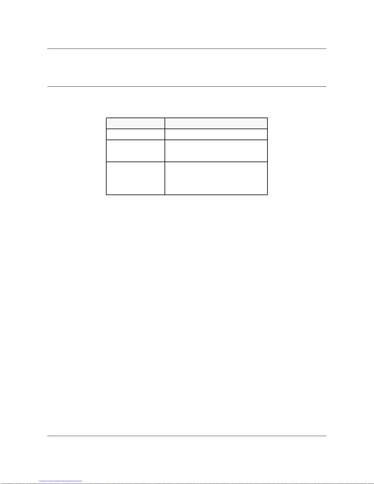
Revision Record
Issue Date Purpose
1.2 97-04-21 Summarize the Vector 2.0.3 Release
1.3 97-05-28 Summarize the Vector 2.0.4 Release
1.4 97-07-15 Summarize the Maintenance Release for VSS2.0.5
1.5 97-09-30 Summarize the Maintenance Release for VSS2.0.6
1.6 97-11-10 Summarize the Maintenance Release for VSS2.0.7
1.7 97-12-04 Summarize the Maintenance Release for VSM 2.0.5
1.8 98-02-16 Summarize the Maintenance Release for VSM 2.0.6
1.9 98-04-17 Summarize the Maintenance Release for VSM 2.0.7
1.9.1 98-06-15 Change the upgrade and downgrade procedures for
and VSS 2.0.8
and VSS 2.0.9
VSS 2.0.9. Correct the Hardware Summary table.
Magellan Vector 2.0 Release Note, Issue 1.9.1
Page 3

Table of Contents
5 Revision Record 2
6 Table of Contents 3
7 Chapter 1 Introduction 5
Configuration Supported 5
Functionality Supported 5
New Hardware 5
VSS 6
VSM 6
MDP 7
Documentation 7
New contents in this release 7
Exclusions 7
8 Chapter 2
Release Considerations 8
3
9 Chapter 3
Service Requests11
Unresolved Service Requests 11
Descriptions of Unresolved Service Requests 11
Solved Service Requests 13
Descriptions of Solved Service Requests 13
10 Chapter 4
Vector documentation 15
NTPs available with this release 15
Installing NTPs online 16
Viewing NTPs 17
Addendum to NTP 241-9501-301 Vector Management Interface User Guide 17
Changes to NTP 241-9501-301 Vector Management Interface User Guide 19
Addendum to NTP 241-9501-301 Vector Management Interface
User Guide 20
Resetting the Network Module 20
Changes to NTP 241-9501- 501 Vector Switch Hardware Maintenance Guide 20
Selecting a MAC address 21
Removing and installing high-speed interconnect (HSI) cables 21
Addendum to NTP 241-9501-301 Vector Management Interface User Guide 24
Addendum to NTP 241-9501-501 Vector Switch Hardware Maintenance Guide 25
Replacing link modules 25
Replacing link select cards 27
Magellan Vector 2.0 Release Notes, Issue 1.9.1
Page 4

4
Appendix A
Upgrade Procedure 30
A.1 In Service Upgrade Procedure 31
A.2 Out of Service Upgrade Procedure 31
A.3 Out of Service Downgrade Procedure 35
Appendix B
Hardware Summary 40
Hardware Vintages 40
Magellan Vector 2.0 Release Note, Issue 1.9.1
Page 5

Chapter 1
Introduction
These release notes highlight the functionality new to this Vector Maintenance
Release in the areas of Hardware, Vector Switching System (VSS) software,
Vector System Manager (VSM) software, and Magellan Data Provider (MDP)
software.This Maintenance Release provides bug fixes for the Vector Switch
Software (VSS) and the Vector System Manager (VSM) software. See chapter
3 for the list of resolved bug fixes.
Included in these release notes:
• Chapter 1 provides an overview of this document and the product
functionality included or excluded for this release.
• Chapter 2 contains general release considerations.
• Chapter 3 lists all the Service Requests that are resolved and high priority
unresolved Service Requests in this release
• Chapter 4 provides a list of the Vector Release 2.0.X Northern Telecom
Publications (NTPs), the procedure for accessing the Vector installation
document (NTP 241-9501-103), and last minute changes and additions to
the NTPs.
5
• Appendix A contains Vector Switching System software upgrade and
installation procedure for Release VSS2.0.8 Vector product.
• Appendix B is a summary of the available hardware.
Configuration Supported
• 2.5 or 5.0 Gbit/s Vector switches with the V ector Switching System (VSS)
software
• The Vector System Manager (VSM)
• The Magellan Data Provider (MDP)
Functionality Supported
New Hardware
• Link Module
• Link Selector
• Netmod Extender
• External Synchronization Interface (ESI)
• Back Plane
Magellan Vector 2.0 Release Notes, Issue 1.9.1
Page 6

6
• Power Module
• Fan Unit
• ASX-1000 air filter
• BIP II
VSS
• Duplex operation (manual, fault-driven and forced SWACT)
• Vector 1.1 ER6 and Vector 2.0.4 functionality
• Hardware inventory
• ESI DS1 BITS
• ESI Line Timing for OC-3/STM-1, J2, DS3, E3, and OC-12/STM-4
Netmods
• Traps (new hardware and SWACT)
• VMI
• OAM cells for OC12, OC3, DS1, DS3, E1, E3, J2 interfaces
• Mixed i960HA SCP pair and i960CF SCP pair configuration support
VSM
• Called Address Screening
• Enhanced Traffic Management
• Enhanced Connection Admission Control (ECAC)
• SVC Failure Cause Counters and Traps
• Vector 1.1 ER6 and Vector 2.0.4 functionality
• Discovery (new hardware)
• Equipment management (new hardware)
• Fault management (new hardware and SWACT)
• Manual and Forced SWACT
• ESI DS1 BITS
• ESI Line Timing for OC-3/STM-1, J2, DS3, E3, and OC-12/STM-4
Netmods
• OAM cells for OC12, OC3, DS1, DS3, E1, E3, J2 interfaces
• VSM-ForeView co-existence
• Called Address Screening
• Enhanced Traffic Management
Magellan Vector 2.0 Release Note, Issue 1.9.1
Page 7

• Enhanced CAC
• SVC Failure Cause Counters and Traps
MDP
• Billing support for fabric redundancy
• Updated BDF formats
Documentation
• Release Notes
• NTPs
New contents in this release
• VSM and VSS bug fixes, see chapter 3.
Exclusions
Excluded from this release:
7
O
• Thermal below 5
C and above 40OC
Excluded from the product:
• Fore IP and SPANS
• ARP server on switch
Magellan Vector 2.0 Release Notes, Issue 1.9.1
Page 8
8
Chapter 2
Release Considerations
The following table lists the latest compatible releases for the products shown:
Product Release Table
Product Release
VSS (on-switch) VSS2.0.9_130_98.tar
VSM (off-switch) VSM2.0.7_131_HP-UX.tar
VSM2.0.7_131_SunOS.tar
MDP (off-switch) mdp096pai_sp413.tar.01
Following MDP Patch is required:
P096_01.tar
Use the following instructions to load the MDP patch:
1) Log on to the MDP server.
2) Download (copy or ftp) the MDP patch file (P096_01.tar) to the MDP
server.
3) Stop any MDP processing by typing:
/iws/mdp/mdpadm shutdown
4) As root user, extract the fix from the tar file:
tar -xvfp P096_01.tar
The new executables will be propagated to the correct directories.
5) Restart MDP processing by typing:
/iws/mdp/mdpadm restart
The MDP BDF output formats have changed in the MDP R9.6 release. See
the Vector Data Collection System User Guide (NTP-241-9501-320) for
details.
Magellan Vector 2.0 Release Note, Issue 1.9.1
Page 9
The Vector Release 2.0.X switch does not support ARP Server functionality.
In cases where customers are running ARPSERVER on Vector Release 1.1,
they need to migrate their ARPSERVER configuration onto a host before or
during the upgrade to a Vector 2.0.X network.
Only one ESI module per switch is supported in this release.
The Partial Packet Policing function of the Enhanced Traffic Management
Feature requires the revision J fabric (PEC NTET51AD).
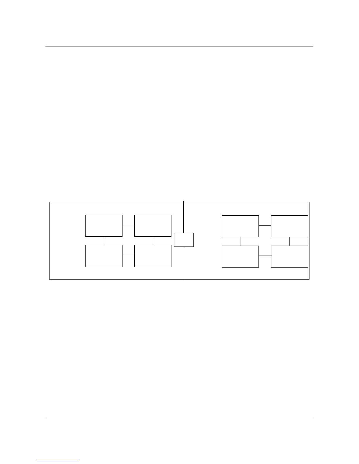
To support a mixed i960CF/HA SCP configuration, you must upgrade the
Vector Switching System (VSS) Software to at least Vector Release 2.0.2. In
the mixed i960CF/HA SCP configuration, each fabric pair must be
configured either with two i960CF SCPs or two i960HA SCPs. As shown in
following figure, the i960CF SCP cannot coexist on the same fabric pair as
the i960HA SCP.
Switch configuration with both i960CF and i960HA processors
9
active plane
inactive plane
fabric 1
i960CF SCP
fabric 3
i960HA SCP
active plane
fabric 1
i960HA SCP
fabric 3
i960CF SCP
OR
i960CF SCP i960HA SCP
fabric 2
fabric 4
The “configuration VCC modify” command is removed in Vector Release
2.0.4 and higher. In order to modify an UPC contract, you must delete the PVC
or PVP and then reprovision the PVC or the PVP with the new UPC contract.
Hot-Swapping (plugging IN and OUT on in-active fabric) the SCP CF
processor card (NTET11AA or ACCA0130-2001 SCP-ASXCF Rev. K/L/M)
can cause permanent damage to the board. The work-around is to remove the
fabric with the SCP card. This problem is resolved in the SCP HA processor
card (that is, NTET11AC).
inactive plane
i960HA SCP i960CF SCP
fabric 2
fabric 4
The ESI card takes 125 seconds to sync to the source. Bellcore standards
indicate that a Stratum 3 clock must lock within 100 seconds.
Magellan Vector 2.0 Release Notes, Issue 1.9.1
Page 10

10
Customers who are running 2.0.3, 2.0.4 or 2.0.7 and before with pmp or
backplane throughpaths configured must use the upgrade and installation
procedure described in Appendix A.
New firmware for the External Synchronization Card has been introduced
which improves the locking characteristics to the BITS timing source. A
version 9 listed under configuration esi show will be displayed for ESI cards
containing the new updated firmware.
Fast SPVC re-routing in the event of a cable failure has been introduced for
OC3 and J2 Netmods.
The reset command introduced in Vector Release VSS2.0.4 under operation
linkmod has been replaced in VSS2.0.8 with the command operation netmod
reset. This VMI command provides the ability re-initialize the specified
netmod. Note: Invoking this command causes service disruptions to all ports
on the affected netmod.
Users who wish to install or migrate to MDP version 10.3.1 should refer to the
Magellan Data Provider User Guide, NTP 241-6001-309 for installation and
operation instructions. MDP 10.3.1 (version MDP103Pax) requires the Solaris
operating system and application of patch 10.3-14.
Magellan Vector 2.0 Release Note, Issue 1.9.1
Page 11

Chapter 3
Service Requests
Unresolved Service Requests
The table below lists all unresolved high priority Service Requests (SRs)
found in Vector Release VSS2.0.8 and VSM2.0.6.
Unresolved Service Requests
SR Number Description
10126103 pt to mpt connections spanning two or more ports with contract
violated.
10127209 Traffic did not swact onto the new active linkselect card
10133471 Unable to modify port bandwidth consistently.
10137752 Switch panic after several hours of MDP connection failures
10139547 All PVCs lost if NM Reset followed immediately by SWACT or
SYNC
11
10132316 Classical IP connection problem during hardware upgrades
Descriptions of Unresolved Service Requests
10126103: pt to mpt connections spanning two or more ports with contract violated.
V iolation of contract (exceeding available bandwidth) on point to multi-point
connections that span 2 or more physical ports on the same netmod will result
with traffic being block on outgoing netmod ports and dropping
synchronization (for switches that are in sync) or in-active fabric panic when
the sync command is invoked (for switches out-of-sync). Recovery is to bring
traffic in-line with the contract, reset the affected netmod (operation netmod
reset) and re-sync the switch.
10127209:
Traffic did not swact onto the new active linkselect card.
During replacement of the Link Select Card, there is a possibility that the
system may loose connection to the netmod or the netmod may get locked up
resulting in stoppage of all traffic. The avoidance procedure is to use the new
Link Select replacement procedure described in Chapter 4 (Vector
Documentation) of these release notes. Recovery is to reset the netmod using
the VMI command operation netmod reset.
Magellan Vector 2.0 Release Notes, Issue 1.9.1
Page 12

12
10133471: Unable to modify port bandwidth consistently.
This problem is actively being investigated. We believe it is related to Flash
memory fragmentation. Suggested avoidance procedure is to perform an
operation flash free command on flash memory every 4 to 6 weeks. This
ensures large blocks of contiguous memory are available for write operations
into flash.
10137752:
One instance of a switch panic due to the MDP being down or an invalid MDP
address specified has been reported from the field. On this occasion, error
messages were displayed on the serial port and SNMP traps generated
(expected) but after 9 hours a switch panic occurred. Addressing the MDP
connection failure will avoid this panic. If this is not possible (MDP
connection problem persists), network operators should disable call recording
until the MDP connection problem is resolved.
10139547:
There is a possibility that performing a sync or swact operation immediately
after a operation netmod reset or removing, inserting or re-seating a Netmod
may result with all connections that originate/terminate on that netmod being
destroyed. This may result with the active and inactive CDBs being corrupted
or sync failures when call recording is enabled.
A voidance procedure is todrop sync prior to invokingoperation netmod reset
or removing, inserting or re-seating a Netmod then wait 2 minutes before
syncing the switch.
There two recovery procedures available.
For systems with corrupted CDBs, the recovery procedure is to reset the CDB
on the active and inactive, perform a restore with the last valid CDB backup
on the active, then sync the switch.
Switch panic after several hours of MDP connection failures
All PVCs lost if NM Reset followed immediately by SWACT or SYNC
For systems were there are no missing connections between the active and
inactive CDB’s but the switch will not sync (with call, recording enabled) the
recovery procedure is to disable call records, sync the switch, drop sync,
enable call recording, reboot the active SCP and sync the switch.
Please refer to the Gotcha describing this problem and recovery in more
details.
10132316:
Classical IP connection problem during hardware upgrades
There is a possibility that SPANS may become unstable or go down on one or
more switches in the network as a result of upgrading or replacing a hardware
component (i.e. Fabric, Linkmod or Linkeselect). This results in classical IP
Magellan Vector 2.0 Release Note, Issue 1.9.1
Page 13
connections being intermittent or going down. There are several possible
recovery procedures available. If this problem occurs, please contact GTS for
the appropriate recovery procedure.
Solved Service Requests
The tables below lists solved Customer and Internal Service Requests (SRs)
for the V ector Switch Software (VSS) and the Vector System Manager (VSM).
Solved Service Requests - VSS
SR Number Description
10067327 setting date, difference from GMT is 00:00
10136334 When UNI 3.0 signaling is down, it will not autonomously restore.
10139834 Vector SCP stuck in initialized state after loading connectionsdue
Solved Service Requests - VSM
SR Number Description
10138835 Off switch VMI command conf ecac ecac always fails.
13
to CDB corruption
Descriptions of Solved Service Requests
10067327:setting date, difference from GMT is 00:00 (VSS)
This fix resolves the problem of not being able to set the timezone. A new
command configuration switch timezone has been added. Previously the date
command contained an offset which was used for this purpose but did not work
correctly .
The new VMI command is;
configuration switch timezone est | cst | mst | pst | akst
where est = eastern standard time, cst = central standard time, mst = mountain
standard time, pst = pacific standard time and alst = alaskan stand time.
The operation date command can still be used to display the current date and
time.
Magellan Vector 2.0 Release Notes, Issue 1.9.1
Page 14

14
10136334: When UNI 3.0 signaling is down, it will not autonomously restore (VSS)
This fix resolves the problem where a 3.0 UNI can be brought into the down
state by changing the mode on a DS3 netmod (i.e. hcs or plcp). When the
mode of the netmod was restored to its original state, the UNI did not restore
itself to the up state. This was because previous versions of VSS2.0 only
attempted to re-establish the UNI once. Network operators had to manually
restart the UNI in question in order to restore it to the up state. Occasionally,
this did not work requiring the UNI to be deleted and recreated to clear the
problem.
In VSS2.0.9, Vector now continuously attempts to re-establish the UNI if it
goes down and carrier is present.
10139834:Vector SCP stuck in initialized state after loading connection
due to CDB corruption (VSS)
This SR (originally included in VSS2.0.7 ER2) is being propagated into
VSS2.0.9. This fix resolves the possibility of CDB corruption when operation
sync is performed. This was observed with customers having very large CDBs.
10138835:
A solution for this SR introduced in VSM2.0.6 had a problem with it. This
problem has been fixed in VSM2.0.7. This resolves a problem in the VMI with
the configuration ecac ecac commands. Execution of these commands in
previous releases always failed displaying the message “?ERROR: Invalid
command”
The configuration ecac ecac command has been replaced with
configuration ecac For example, what used to be configuration ecac ecac
enable is now configuration ecac enable.
Off switch VMI command conf ecac ecac always fails.(VSM)
Magellan Vector 2.0 Release Note, Issue 1.9.1
Page 15

Chapter 4
Vector documentation
This chapter contains information about the Northern Telecom Publications
(NTP) available with this Vector Release. The information in this chapter is
organized as follows:
• NTPs available with this release
• installing NTPs online
• addendums to NTP 241-9501-301, Vector Management Interface User
Guide
• changes to NTP 241-9501-301, Vector Management Interface User Guide
• changes to NTP 241-9501-501, Vector Switch Hardware Maintenance
Guide
15
Please note that NTP 241-9501-103, 241-9501-301 and 241-9501-501 are
updated for Release 2.0.3. To ensure you have the most recent version, you
can:
• obtain the NTP from the Vector 2.0 hardware shipment
• order the NTP via your usual channels
NTPs available with this release
• NTP 241-9501-010, Vector General Description Guide
• NTP 241-9501-501, Vector Switch Hardware Maintenance Guide
• NTP 241-9501-103, Vector Site Planning and Installation Guide
• NTP 241-9501-301, Vector Management Interface User Guide
• NTP 241-9501-302, Vector System Manager User Guide
• NTP 241-9501-320, Vector Data Collection System User Guide
• NTP 241-9501-306, Vector System Manager Error Messages
1
2
Note1: The NTP 241-9501-301, Vector Management Interface User Guide is
renamed to NTP 241-9501-301, VMI User Guide for Vector in the paper
version.
Magellan Vector 2.0 Release Notes, Issue 1.9.1
Page 16

16
Note2: The NTP 241-9501-320, Vector Data Collection System User Guide is
available in paper only (that is, not in UniHelp).
Installing NTPs online
1 Login as root on your workstation.
2 Select a UNIX xterm window.
3 Set the read/write permissions by entering the UNIX command
umask 022
4 Enter the cshell operation by entering
csh
5 Create a vector home directory by entering
mkdir -p /usr/nortel/magellan/vector
6 Select a temporary directory for extracting the UniHelp (NTP software)
cd /usr/tmp
7 From the VSM or VSS CD or tape supplied by Nortel, put the VSM or VSS
tar file into /usr/tmp
tar -xvf <device name>
where <device name> for HP platforms is typically /dev/dsk/c201d2s0 for
CD and /dev/rmt0m for tape, or for Sun platforms is typically /dev/sr0 for
CD and /dev/rst<n> for tape, where <n> is a number from 0 through 9.
8 Extract the installation document tar file to the vector home directory
cd /usr/nortel/magellan/vector
tar -xvf /usr/tmp/<tar file>
where <tar file> is sunosdoc.tar for Sun platforms and hpuxdoc.tar for HP
platforms.
Magellan Vector 2.0 Release Note, Issue 1.9.1
Page 17

Viewing NTPs
1 Change directory to the NTP directory
2 Run the viewer software by entering
17
cd /usr/nortel/magellan/vector/instldoc
instldoc.run*
The viewer software starts, with the NTP ready to view.
Addendum to NTP 241-9501-301
Guide
This section provides an addendum to NTP 241-9501-301, Vector
Management Interface User Guide, chapter 6, “VMI Configuration
Commands”, section, “Showing the configuration of the virtual path
connections (VPCs)”.
VMI command configuration vpc obshow displays the overbooking values
associated with permanent virtual paths (PVPs). This command is only
available through the Vector management interface (VMI). The only VSM
access to this command is through a telnet session to VMI.
The command configuration vpc obshow displays the overbooking values
used by the system to calculate the equivalent bandwidth for both originating/
terminating paths and through paths.
configuration vpc obshow [<port>] [<vpi>]
For example, to view the overbooking values of all PVPs, type:
Vector Management Interface User
localhost::> configuration vpc obshow
Input Output
Port VPI Port VPI VBROB BuffOB
4D2 0 terminate N/A N/A
Magellan Vector 2.0 Release Notes, Issue 1.9.1
Page 18

18
4E2 0 terminate N/A N/A
4E3 0 terminate N/A N/A
4E4 0 terminate N/A N/A
4CTL 0 terminate N/A N/A
originate 4D2 0 100 100
originate 4E2 0 100 100
originate 4E3 0 100 100
originate 4E4 0 100 100
originate 4CTL 0 100 100
4B1 33 4B2 33 200 100
4B2 33 4B1 33 400 100
Notice the two through paths (last two row entries in the example), which
report having VBR bandwidth overbooking (VBROB) values of 200 and 400
respectively and VBR output buffer overbooking (BuffOB) values of 100 and
100.
For a more concise report to display all through paths with an input port and a
virtual path identifier (VPI), for example, port 4B1 and VPI 33:
localhost::> configuration vpc obshow 4B1 33
Input Output
Port VPI Port VPI VBROB BuffOB
4B1 33 4B2 33 200 100
To display all through paths from an input port, for example, port 4B2:
localhost::> configuration vpc obshow 4B2
Input Output
Port VPI Port VPI VBROB BuffOB
4B2 33 4B1 33 400 100
Magellan Vector 2.0 Release Note, Issue 1.9.1
Page 19

19
Changes to NTP 241-9501-301
Guide
This section provides changes to the NTP 241-9501-301, Vector Management
Interface User Guide, chapter 4, “Connection admission control for SVCs”,
section, “Aggregate maximum bandwidth for all switched virtual circuits”,
page 82, must be read as follows:
For each Quality of Service (QoS) setting, bandwidth added to the aggregate
SVC maximum bandwidth is as follows:
• for a CBR SVC connection, its peak cell rate (PCR) is counted in this
parameter
• for a VBR SVC connection, its “equivalent bandwidth” is counted in this
parameter
• for a UBR SVC connection, its representative bandwidth is counted in this
parameter
• this aggregate bandwidth must be larger than the maximum bandwidth
parameter for each SVC
• the aggregate SVC maximum bandwidth can be provisioned a different
value for each of the users-to-network and network-to-user directions
Vector Management Interface User
• the pre-configured maximum aggregate bandwidth for all the SVCs is
compared against:
equivalent bandwidth of the connection to be
admitted (in case of a UBR connection, it will
equal the corresponding UBR representative
bandwidth)
SVC connections (in case of a UBR connection, each
SVC connection will consume 3 cells per second)
number of active UBR connections on the fabric *
UBR representative bandwidth
If the maximum pre-configured aggregate bandwidth is reached or
exceeded no additional SVCs can be admitted.
+ Bandwidth currently consumed by all
+
Magellan Vector 2.0 Release Notes, Issue 1.9.1
Page 20

20
Addendum to NTP 241-9501-301 Vector Management Interface
User Guide
This section provides information for a new feature that is not documented
in NTP 241-9501-301, Vector Management Interface User Guide,
Chapter 11, “VMI operation commands,” page 293.
Resetting the Network Module
Vector 2.0.8 and higher supports the ability to reset a network module.
Caution: Invoking this command causes service disruptions to all ports on
the affected netmod.
T o reset the network module, enter the command netmod reset at the level
operation:
operation netmod reset <module>
where:
module is the link module (A to D) you want to reset.
For example:
localhost::> operation netmod reset B
resets and initializes netmod B.
Once the command is invoked, VMI displays the following message:
Resetting the network module will destroy all
existing connections which are already
configured on the network module.
Reset Network Module - B - [n]?
Enter y (yes) to reset the network module or enter n (no) or press
<Return> to cancel the reset. The default is no.
Changes to NTP 241-9501- 501
Guide
This section contains the following procedures: selecting a MAC address,
removing an HSI cable and installing an HSI cable.
Vector Switch Hardware Maintenance
Magellan Vector 2.0 Release Note, Issue 1.9.1
Page 21

Selecting a MAC address
The MAC address is displayed by a menu selection accessible when the SCP
board is reset or on a power-up. The following procedure provides changes to
NTP 241-9501-501, Vector Switch Hardware Maintenance Guide, chapter 4,
“Fabric Shelf”.
Selecting a MAC address
1 As the diagnostics run, depress the next switch
2 When “FLASH?” is displayed, depress the next switch until “OPTIONS” is
displayed.
3 Depress the select switch to select “OPTIONS”
4 “MAC address?” will be displayed.
5 Depress the select switch again to select “MAC Address?”
6 The MAC address will be scrolled repeatedly on the screen
7 Depressing Next switch will return you to the main menu and display “FLASH?”
Removing and installing high-speed interconnect (HSI) cables
T o replace an HSI cable, perform the following procedures in the order shown:
21
• Removing an HSI cable
• Installing an HSI cable
Removing an HSI cable
Tools and equipment required:
• wire cutters or side cutting pliers
1 At the cable guides on the fabric shelf fan filter, cut and remove the tie wrap that
holds the HSI cables together.
2 Cut and remove the tie wraps that hold the HSI cables together at regular
intervals along the cable route from the extension shelf to the fabric shelf.
CAUTION
Make sure that you perform the next two steps in the order listed.
3 Disconnect the HSI cable from the link select card on the extension shelf.
4 Disconnect the HSI cable from the link module on the fabric shelf.
5 At the back of the switch frame, carefully pull the cable out from the fabric shelf
through the cable management tray.
Magellan Vector 2.0 Release Notes, Issue 1.9.1
Page 22

22
6 At the back of the switch frame, carefully pull the cable out from the extension
shelf over the top of the cooling unit.
Installing an HSI cable
Tools and equipment required:
• tie wraps
• replacement HSI cable
For information about the HSI cable connections between the fabric and
extension shelf, see Table 3 at the end of this procedure.
1 Place one end of the HSI cable at the front of the extension shelf and route the
other end up to the cable management area on top of the cooling unit, then
through the cable management unit to the back of the switch frame.
2 From the back of the switch frame, route the HSI cable up the back of the frame,
through the cable guide on the side of the fabric shelf fan filter, to the back of the
cable management tray.
3 Route the HSI cable over the cable management tray to the front of the switch
frame.
4 From the front of the switch frame, route the HSI cable from the cable tray straight
down to the fabric shelf. If the cable does not reach the front of the fabric shelf,
pull some slack along the cable route from the extension shelf.
Note: Make sure there is enough cable length at the front of the extension
shelf to connect the HSI cable to a link select card.
CAUTION
Make sure that you perform the next two steps in the order listed.
5 Connect the HSI cable to a link module in the fabric shelf.
Note: Make sure the HSI EMI gasket is in place on the link module.
6 Connect the HSI cable to the link select card in the extension shelf.
Note: Make sure the HSI EMI gasket is in place on the link select card.
7 Tie wrap the HSI cables together, at regular intervals along the cable route from
the extension shelf to the fabric shelf, approximately 6 to 8 inches apart.
8 At the cable guides on the fabric shelf fan filter, tie wrap the HSI cables together
and through two of the holes in the guide channel.
Magellan Vector 2.0 Release Note, Issue 1.9.1
Page 23

The following table provides connection information for the proper HSI cable
connections between the fabric shelf and extension shelf:
Table 1
Linkmods on fabric shelf Link select card on upper
extension shelf
Fabric# Slot# Position Slot#
1 4 1A X2
1B X4
5 1C X8
1D X10
2 7 2A X3
2B X5
8 2C X9
2D X11
3 10 3A X14
23
3B X16
11 3C X20
3D X22
4 13 4A X15
4B X17
14 4C X21
4D X23
Magellan Vector 2.0 Release Notes, Issue 1.9.1
Page 24

24
Addendum to NTP 241-9501-301
Guide
To prepare a switch using VMI commands prior to the replacement of a link
select card, perform the following procedure.
Preparing the switch for replacement of a link select card
1 Switch traffic away from the fabric with the link select cards needing replacement,
if it is not already on the inactive side of the subswitch, by entering the command:
localhost::> operation swact
Answer Y to the following message:
Are you sure you want to manually switch activity [n]?
2 Drop the synchronization of the switch by entering the command: localhost:: >
operation dropsync
A system response will display configuration information that varies depending on
the configuration of your switch.
3 Replace the link select card by performing procedure “Replacing link select
cards” on page 27.
CAUTION
Loss of service
Resetting the link select card will cause all the existing connections to
be dropped. However, after the link select card is initialized, the PVCs
will be automatically reestablished.
Vector Management Interface User
4 Reset the netmod by entering the command: localhost::> operation netmod
reset <A, B, C or D>
Where A, B, C or D designates the netmod in the fabric associated with the link
select card that is being replaced. In the example below, netmod A is being
replaced.
Answer Y to the following message:
Reset Network Module - A - [n]?
5 Repeat steps 3 and 4 for the remaining three link select cards on that inactive
fabric, if required.
6 Resynchronize the switch by entering the command: localhost::> operation
sync
Answer Y to the following message:
Are you sure you want to sync the switch [n]?
Answer Y to the following message:
Do you wish to wait till your action is complete [y]?
7 Switch traffic back to the fabric with the newly replaced link select cards by
entering the command: localhost::> operation swact
Magellan Vector 2.0 Release Note, Issue 1.9.1
Page 25

Answer Y to the following message:
Are you sure you want to manually switch activity [n]?
8 Synchronize the switch to the newly active fabric by entering the command:
localhost::> operation sync
Answer Y to the following message:
Are you sure you want to sync the switch [n]?
Answer Y to the following message:
Do you wish to wait till your action is complete [y]?
25
Addendum to NTP 241-9501-501
Maintenance Guide
This addendum contains the following procedures: replacing link modules,
removing a link select card and installing a link select card.
Replacing link modules
Link modules are hot-swappable, so that they can be removed and replaced on
a switch that is inservice providing the procedure is performed on the inactive
side of the subswitch. Make sure that you have been directed by a switch
operator before performing this procedure.
CAUTION
Loss of service
Any action performed on a live switch can result in loss of service.
Before starting work, make sure you have located the correct
component, that you are working on the inactive side of the subswitch,
and that the network operator is aware of your actions.
Replacing link modules
Tools and equipment required:
Vector Switch Hardware
• static wrist wrap
• slot head screwdriver
• replacement link module
CAUTION
Use a grounding strap when handling any electronic component.
Magellan Vector 2.0 Release Notes, Issue 1.9.1
Page 26

26
1 Perform a SWACT to switch traffic away from the fabric with the link modules
needing replacement, if it is not already on the inactive side of the subswitch, by
performing step 1 from “Preparing the switch for replacement of a link select card”
on page 24.
2 Locate the link module to be replaced as indicated by the operator.
3 If the LED status indicator is NOT solid green, go to step 5.
4 A solid green LED status indicator on the link module indicates that the card is
carrying traffic.Contact the network operator to have traffic switched away from
the link module. Continue with the next step when the LED changes to NOT solid
green.
5 If the LED status indicator on the link module is flashing green or OFF, go to step
9.
6 If the LED status indicator on the link module is red, then the HSI cable may be
disconnected or defective.
7 Check the connections of the HSI cable at the link module and at the link select
card.
8 Observe the color of the LED:
a. If the LED is now green (solid or flashing) and stays in that state, then inform
the network operator that you completed this procedure.
b. Otherwise continue with step 9.
9 Place the static wrist strap on your wrist and connect the wrist strap cord to the
ESD jack located below the fabric shelf.
10 Disconnect the HSI cable from the corresponding link select card.
11 Disconnect the HSI cable from the link module to be replaced.
CAUTION
Make sure that you have disconnected both ends of the HSI cable.
12 Use the screwdriver to loosen the two captive fasteners on either edge of the link
module.
13 By pulling firmly and gently on the two captive fasteners, remove the link module
from the switch fabric.
14 Place the link module in an anti-static bag or box, and put aside.
15 Remove the replacement link module from its anti-static bag or box.
16 Insert the replacement module by sliding it into the card guides. Push firmly to
seat the link module so that the faceplate is flush with the switch fabric.
17 Re-tighten the captive fasteners.
Magellan Vector 2.0 Release Note, Issue 1.9.1
Page 27

18 Re-connect the HSI cable to the link module.
19 Re-connect the HSI cable to the link select card.
20 Observe the color of the LED:
a. If the LED is now green (solid or flashing) and stays in that state, then go to
step 21.
b. Otherwise replace the HSI cable (see “Removing and installing high-speed
interconnect (HSI) cables” on page 21).
21 Inform the network operator that you completed this procedure.
Replacing link select cards
To replace link select cards in a fabric, perform the following procedures:
• Preparing the switch for replacement of a link select card
• Removing and installing a link select card
CAUTION
Loss of service
Although you are working on an inactive fabric of the switch, the
following actions are service affecting!
27
CAUTION
Link Select cards are to be hot-swapped only for replacement of a
failed unit.
Procedure step summary
1 Switch traffic away from the fabric with the link select cards to be replaced.
2 Drop the synchronization of the switch.
3 Replace the link select card.
4 Reset the netmod.
5 Repeat steps 3 and 4 for the remaining three link select cards on the inactive
fabric, if required.
6 Resynchronize the switch.
Removing and installing a link select card
Tools and equipment required:
Magellan Vector 2.0 Release Notes, Issue 1.9.1
Page 28

28
• slot head screwdriver
• static wrist wrap
• replacement link select card
CAUTION
Loss of service
Any action performed on a live switch can result in loss of service.
Before starting work, make sure you have located the correct
component and that the network operator is aware of your actions.
CAUTION
Use a grounding strap when handling any electronic component.
1 Obtain the following information from the network operator:
a. link select card identification
b. shelf slot number
2 Locate the link select card to be replaced.
3 If the LED status indicator on the link select card is NOT solid green, go to step 5.
4 A solid green LED status indicator on the link select card indicates that the card
is carrying traffic. Contact the network operator to have traffic switched away from
the link select card. Continue with the next step only when the LED changes to
NOT solid green.
5 If the LED status indicator on the link select card is flashing green or OFF, go to
step 9.
6 If the LED status indicator on the link module is red or amber, then the HSI cable
may be disconnected or defective.
7 Check the connections of the HSI cable at the link module and at the link select
card.
8 Observe the color of the LED:
a. If the LED is now green (solid or flashing) and stays in that state, then inform
the network operator that you completed this procedure.
b. Otherwise continue with step 9.
9 Place the static wrist strap on your wrist and connect the wrist strap cord to the
ESD jack located below the fabric shelf.
10 Using the screwdriver if necessary , disconnect the HSI cable from the link select
card.
Magellan Vector 2.0 Release Note, Issue 1.9.1
Page 29

11 Lift the top latch while pushing down on the bottom latch, and begin to slide the
link select card towards you.
12 Place the link select card in an anti-static bag or box, and put aside.
13 Remove the replacement link select card from its anti-static bag or box.
14 Carefully slide the replacement link select card in the slot until the connector at
the back of the card contacts the connector on the backplane of the shelf.
15 The two latches at the top and bottom of the card should now be in the latch rail
to lock the link select card in place.
16 Actuate the latches to install the card.
17 Re-connect the HSI cable to the link select card.
18 Observe the color of the LED:
a. If the LED is now green (solid or flashing) and stays in that state, then inform
the network operator that you completed this procedure.
b. Otherwise replace the HSI cable (see “Removing and installing high-speed
interconnect (HSI) cables” on page 21).
19 Inform the network operator that you completed this procedure.
29
Magellan Vector 2.0 Release Notes, Issue 1.9.1
Page 30

30 Appendix A
Appendix A
Upgrade Procedure
One of two upgrade procedures are available for upgrading to Vector Release
VSS2.0.9. Use the following guidelines to determine which upgrade procedure
to use.
• Customers who are upgrading from VSS2.0.8 or higher (all
configurations) must use the upgrade procedure provided in the Software
Installation and Commissioning for Vector and AccessShelf NTP 2419501-200.
• Customers who are upgrading from VSS2.0.7 and do not have pmp
connections configured must use the upgrade procedure provided in the
Software Installation and Commissioning for V ector and AccessShelf NTP
241-9501-200.
• Customers who are running Vectors with release VSS2.0.7 and have been
configured with point to multipoint connections must use the procedure
described in section A.2 Out of Service Upgrade procedure. This is an out
of service upgrade procedure which must be used in order to correctly
recover all the point to multipoint connections.
• Customers who are running Vectors with release VSS2.0.6 or earlier must
use the procedure described in section A.2 Out of Service Upgrade
procedure.
There is also an out of service downgrade described in A.3 Out of Service
Downgrade procedure.
WARNING There should NOT be any hardware or provisioning
changes done during either upgrade or downgrade procedure.
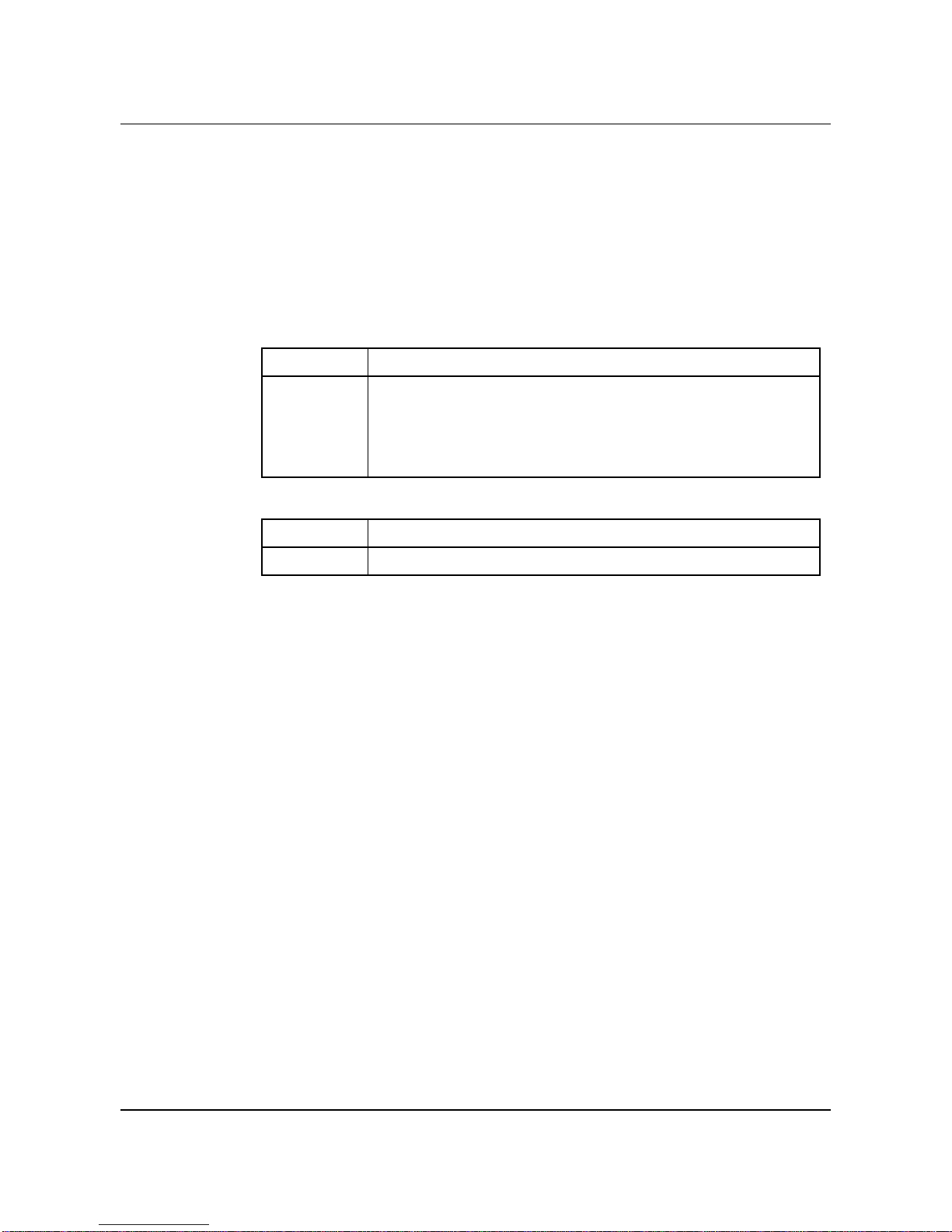
The following table summarizes the previous bullets.
Table 1 Upgrade procedures to use to upgrade to release 2.0.9
Upgrade From Condition Procedure to Use
2.0.8 All configurations In Service Upgrade
2.0.7 No PMP In Service Upgrade
2.0.7 PMP connections Out of Service Upgrade
2.0.6 or earlier All configurations Out of Service Upgrade
Magellan Vector 2.0 Release Note, Issue 1.9.1
Page 31

A.1 In Service Upgrade procedure
Please refer to the Software Installation and Commissioning for Vector and
AccessShelf NTP 241-9501-200, section entitled ‘Upgrading VSS 2.0 to later
VSS 2.0 versions’.
A.2 Out of Service Upgrade procedure
The following Procedure 20, Procedure 21, Procedure 22 and Procedure 23
guide software installers through a 2.5G and 5.0G redundant switch software
upgrade. The procedures assume that all fabrics are in sync.
Note 1: References to Fabric pair 1-2 or Fabric pair 3-4 in the following
procedures refer to the active fabric of the pair.
Procedure 20
Backing up the CDB
Back up the CDB on Fabric pair 1-2 and Fabric pair 3-4 (for 5.0G configuration).
Appendix A 31
1 Telnet to the remote host and log in.
2 Access the directory
cd /tftpboot
3 Create two unique files to which the backups for each sub-switch are to be sent:
touch <user-assigned backup file name>
The following example places the fabric (board) numbers into each filename:
touch Fabric_1-2_backup_date
touch Fabric_3-4_backup_date
Note:
Note:
4 Change the permissions on the four new files to allow read/write/execute access
by the system or any user:
chmod 777 <user-assigned backup file name>
5 Quit from the telnet session.
quit
A backup from fabric pair 1-2 can only be restored to fabric pair 1-2.
A backup from fabric pair 3-4 can only be restored to fabric pair 3-4.
tftpboot
:
6 Telnet to Fabric pair 1-2 on the switch and log in to the Vector management
interface (VMI):
Magellan Vector 2.0 Release Notes, Issue 1.9.1
Page 32

32 Appendix A
telnet <switch name>
login: vmi
password: <password>
Note:
active fabric.
7 After reviewing the syntax of backup command described below, enter this
command string to access the CDB command level and to start the backup:
operation CDB backup <host>:<path to remote file>
where <host> is the IP address of the host tftpboot server to which the CDB file
is backed up, and <path to remote file> is the path and filename of the remote
backup file to which the CDB file is to be backed up. For example, the
<path to remote file> would be Fabric_1-2_backup_date.
Note:
from the tftp user’s home directory to the directory of the remote file. For a Sun
workstation, where there is no tftp user, specify the full path name to the directory
of the remote file.
8 When the backup has completed, the following message is displayed:
CDB backup was successful.
When you telnet to a switch pair, the system will automatically route to the
For an HP workstation, where there is a tftp user, specify the path name
Note: The backed-up CDB should be kept in a safe place. It would be
required if the need for a downgrade arose. The downgrade procedure
requires a CDB of the same version as the software release being
downgraded to. For example, if the user wants to downgrade from release
2.0.9 to release 2.0.8, then a 2.0.8 version of the CDB MUST BE used.
9 For a 5.0G configuration, repeat steps 6 through 8 for the other active sub-switch
(fabric pair 3-4).
Procedure 21
1 Loading the new software into flash memory
Remove old loads from flash on fabric pair 1-2
a. localhost::> operation flash
localhost::operation flash> dir
The list of file names is shown, for example:
V208_060
CURRENT
b. Delete all current loads. Vector 2.0 supports only one load in flash.
localhost::operation flash> delete <file>/foreos.exe
localhost::operation flash> delete <file>
Magellan Vector 2.0 Release Note, Issue 1.9.1
Page 33

Appendix A 33
Where <file> is the name of the file to be deleted (i.e. V208_060).
2 Enter the
free
command to clean up (de-fragment) flash memory
localhost::operation flash> free
Note:
The Vector 2.0 software load requires approximately 1.2 MB for the
software and up to 0.5MB to store a copy of the CDB during a switch of activity.
The amount of free space available after deleting the old software and
defragmenting flash memory should be greater than the new software load size
plus the 0.5 MB for the CDB file.On fabric pair 1-2, download new software to the
active fabric:
localhost::> operation load <remotehost>:<full path to remotefile>
Where <remotehost> is the IP address of the remote host on which the upgrade
file resides and <full path to remotefile> is the full path name of the upgrade file.
For example:
localhost::> operation load <ip address>:/tftpboot/VSS2.0.9_130_98.tar
where <ip address> is the ip address of the remote machine (for example,
1.2.3.4)
Note:
DO NOT use the upgrade command. This command is used for previous
Vector releases.
3 Verify that the load is in flash.
localhost::> operation flash
localhost:: operation flash> dir
The list of file names is shown, for example:
V209_130
CURRENT
4 For a 5.0G configuration, repeat steps 1 through 4 for the other active sub-switch
(fabric pair 3-4).
Procedure 22
Loading the other fabric
1 The new software has been loaded on the active flash. The user must now switch
the fabric activity (perform a SWACT) and load the software onto the previously
inactive fabric.
localhost::> operation swact
The following message appears:
A switch of activity will affect user traffic,
billing data collection and performance information.
Are you sure you want to manually switch activity [n]?
Answer Y to the message.
Magellan Vector 2.0 Release Notes, Issue 1.9.1
Page 34

34 Appendix A
Note: The switch is no longer in SYNC and will remain as such until the
last step of the upgrade procedure.
2 After SWACT, you must telnet to both active fabrics (from fabric pairs 1-2 and 3-
4 (5.0G configuration) to reestablish a VMI session on the newly activated fabrics.
3 You can now free-up space on the flash and load the new Vector software on the
newly active side as per steps 1 through 5 of Procedure 21.
4 After repeating steps 1 through to 5, the flashes on both sides will have been
loaded with Vector release 2.0.X software. The software can now be installed into
the switch.
Procedure 23
Installing the new software
1 On fabric pair 1-2, list the inactive fabric flash version.
localhost::> operation mate version
The software downloaded previously should appear. For
example;
Retrieved INACTIVE version load info...
Software versions installed : V209_130
Current software version is V208_060
The ‘installed’ version is the version currently on flash. The ‘current software
version’ is the version of software running in the switch.
2 Set the current version to the new software for fabric pair 1-2:
localhost::> operation mate version <software load>
where <software load> is the name of the new software load displayed as
‘installed’ in the previous step
(for example, V209_130).
3 Reboot the mate fabric for fabric pair 1-2
localhost::> operation mate reboot
4 Repeat steps 1 through 3 for the other active sub-switch (fabric pair 3-4).
5 Set the version on the currently active fabric, wait 2 minutes for the mate to finish
rebooting (step 3) then reboot the active fabric.
a. localhost::> operation version
Software versions installed : V209_130
Current software version not set
The ‘installed’ version is the version of software currently copied onto flash.
Magellan Vector 2.0 Release Note, Issue 1.9.1
Page 35

Appendix A 35
b. Set the version for the current active fabric
localhost::> operation version V209_130
c. The user is now prompted to reboot the switch
Reboot the switch [y]?
Answer Y to the previous message
Note: The switch is out of service and will not carry traffic until the reboot
is complete. Downtime is dependent on the hardware setup and number of
connections configured.
6 Repeat step 5 for the other active sub-switch (fabric pair 3-4)
7 Once the switch has rebooted, the following message will appear on the serial
connection:
INFO: CC finished Performing Switch Maintenance - Sync allowed
The user can now SYNC the switch by doing:
a. localhost::> operation sync
Are you sure you want to sync the switch [n]?
b. Answer Y to the previous question
The switch has now been upgraded to 2.0.9 and is in SYNC.
A.3 Out of Service Downgrade Procedure
The following Procedure 23, Procedure 24 and Procedure 25 guide software
installers through a 2.5G and 5.0G redundant switch software downgrade. The
procedures assume that all fabrics are in sync.
Note: References to Fabric pair 1-2 or Fabric pair 3-4 in the following
procedures refer to the active fabric of the pair.
Before beginning, the installer must obtain a version of the CDB which will be
compatible with the version of software being downgrade to. For example, if
the user is downgrading from release 2.0.9 to release 2.0.7, the 2.0.7 CDB
must be obtained. The 2.0.7 CDB should have been backed up prior to
Magellan Vector 2.0 Release Notes, Issue 1.9.1
Page 36

36 Appendix A
upgrading the switch. Failure to use the proper CDB could result in CDB
corruption and an inability to properly SYNC the fabrics once the procedure is
complete.
Procedure 24
Backing up the CDB
Back up the CDB on Fabric pair 1-2 and Fabric pair 3-4 (for 5.0G configuration).
This CDB will NOT be used for the downgrade procedure, however, it could be
very useful for understanding problems which led to the necessity to perform an
out of service downgrade.
1 Telnet to the remote host and log in.
2 Access the directory
cd /tftpboot
3 Create two unique files to which the backups for each sub-switch are to be sent:
touch <user-assigned backup file name>
The following example places the fabric (board) numbers into each filename:
touch Fabric_1-2_backup_date
touch Fabric_3-4_backup_date
Note:
4 Change the permissions on the four new files to allow read/write/execute access
by the system or any user:
chmod 777 <user-assigned backup file name>
5 Quit from the telnet session.
quit
6 Telnet to Fabric pair 1-2 on the switch and log in to the Vector management
interface (VMI):
A backup from fabric pair 1-2 can only be restored to fabric pair 1-2.
tftpboot
:
telnet <switch name>
login: vmi
password: <password>
Note:
active fabric.
7 After reviewing the syntax of command backup described below, enter this
command string to access the CDB command level and to start the backup:
operation cdb backup <host>:<path to remote file>
where <host> is the IP address of the host tftpboot server to which the CDB file
is backed up, and <path to remote file> is the path and filename of the remote
backup file to which the CDB file is to be backed up. For example, if the active
Magellan Vector 2.0 Release Note, Issue 1.9.1
When you telnet to a switch pair, the system will automatically route to the
Page 37

Appendix A 37
fabric as determined in step 7 is fabric 1, the <path to remote file> would be
Fabric_1-2_backup_date.
Note:
For an HP workstation, where there is a tftp user, specify the path name
from the tftp user’s home directory to the directory of the remote file. For a Sun
workstation, where there is no tftp user, specify the full path name to the directory
of the remote file.
8 When the backup has completed, the following message is displayed:
CDB backup was successful.
9 For a 5.0G configuration, repeat steps 6 through 8 for Fabric pair 3-4.
Procedure 25
Loading the previous software into flash memory
1 Remove old loads from flash on fabric pair 1-2
a. localhost::> operation flash
localhost::operation flash> dir
The list of file names is shown, for example:
V209_130
CURRENT
b. Delete all current loads. Vector 2.0 supports only one load in flash.
localhost::operation flash> delete <file>/foreos.exe
localhost::operation flash> delete <file>
Where <file> is the name of the file to be deleted (i.e. V209_130).
2 Enter the
free
command to clean up (de-fragment) flash memory
localhost::operation flash> free
Note:
The Vector 2.0 software load requires approximately 1.2MB for the
software and up to 0.5MB to store a copy of the CDB during a switch of activity.
The amount of free space available after deleting the old software and
defragmenting flash memory should be greater than the new software load size
plus the 0.5 MB for the CDB file.
3 On fabric pair 1-2, download new software to the active fabric:
localhost::> operation load <remotehost>:<full path to remotefile>
Where <remotehost> is the IP address of the remote host on which the upgrade
file resides and <full path to remotefile> is the full path name of the upgrade file.
For example:
localhost::> operation load <ip address>:/tftpboot/VSS2.0.7_090_98.tar
Magellan Vector 2.0 Release Notes, Issue 1.9.1
Page 38

38 Appendix A
where <ip address> is the ip address of the remote machine (for example,
1.2.3.4)
Note:
Vector releases.
4 Verify that the load is in flash.
localhost::> operation flash
localhost:: operation flash> dir
The list of file names is shown, for example:
V207_090
CURRENT
5 For a 5.0G configuration, repeat steps 1 through 4 for fabric pair 3-4.
Procedure 26
Installing the new software
DO NOT use the upgrade command. This command is used for previous
The old version of software installed or loaded onto the flash. The user must
now restore the SAME-VERSION and SAME-SWITCH FABRIC CDB.
1 On the newly active fabric, restore the previously backed up CDB which is the
same as the software version to be downgraded to
localhost::> operation cdb restore <ip address>:/<path>/<backup_CDB>
where ip address is the IP address of the tftpboot server
path is the directory where the backed-up CDB is contained
backup_CDB is the CDB of the same version as the downgrade-to
software
2 Repeat the previous step using the other active fabric (fabric pair 3-4)
3 On fabric pair 1-2, list the inactive fabric flash version.
localhost::> operation mate version
The software downloaded previously should appear. For
example;
Retrieved INACTIVE version load info...
Software versions installed : V207_090
Current software version is V209_130
The ‘installed’ version is the version currently on flash.
The ‘current software version’ is the version of software
running in the switch.
4 Set the current version to the new software for fabric pair 1-2:
Magellan Vector 2.0 Release Note, Issue 1.9.1
Page 39

Appendix A 39
localhost::> operation mate version <software load>
where <software load> is the name of the new software load displayed as
‘installed’ in the previous step
(for example, V209_130).
5 Reboot the mate fabric for fabric pair 1-2
localhost::> operation mate reboot
6 Repeat steps 3 through 5 for the other active sub-switch (fabric pair 3-4).
7 SYNC to the other fabric by doing:
localhost::> operation sync noloopback
8 Once the switch has stabilized, switch activity by doing:
localhost::> operation swact
9 Load the version of software to be downgraded to (same as other fabric) into the
flash following the instructions detailed in Procedure 24. Do this on the newly
active fabric.
10 Once the switch has stabilized, restore the previously backed-up CDB which is
the same as the software version to be downgraded to.
localhost::> operation cdb restore <ip address>:/<path>/<backup_CDB>
where ip address is the IP address of the tftpboot server
path is the directory where the backed-up CDB is contained
backup_CDB is the CDB of the same version as the downgrade-to
software
11 Once the switch has stabilized, SYNC the two fabrics:
localhost::> operation sync
Magellan Vector 2.0 Release Notes, Issue 1.9.1
Page 40

40 Appendix
Appendix B
Hardware Summary
Hardware Vintages
Listed below are the minimum and current hardware vintages required in the
Vector Release 2.0.X switch.
Table 2: Vector 2.0 Material Lineup
Minimum Support
Product Code
NTET09AB NTET09AD - EMC compliant AMCH0011-2202, Management Station
NTET13AA NTET13AC - EMC compliant ACCA0056-2022 NM-2/DS3C
NTET14AA NTET14AC - EMC compliant ACCA0056-2012 NM-4/DS3C
NTET15AA NTET15AC - EMC compliant ACCA0056-2042 NM-2/E3C
NTET16AA NTET16AC - EMC compliant ACCA0056-2032 NM-4/E3C
NTET47AB - EMC Waivers ACCA0425-2042 NM-1/622SMIRC
NTET18AA NTET18AC - EMC compliant ACCA0055-2012 NM-6/DS1C
NTET17AA NTET17AC - EMC compliant ACCA0055-2022 NM-2/DS1C
NTET34AB NTET34AC - EMC compliant ACCA0055-2032 NM-6/E1C
NTET33AB NTET33AC - EMC compliant ACCA0055-2042 NM-2/E1C
NTET23AC NTET23AC - EMC compliant ACCA0126-2012 NM-2/155SMLRC
NTET24AC NTET24AC - EMC compliant ACCA0126-2022 NM-4/155SMLRC
NTET19AC NTET19AC - EMC compliant ACCA0126-2052 NM-4/155MMSCC
NTET20AC NTET20AC - EMC compliant ACCA0126-2062 NM-4/155MMSTC
Current Support
Product Code
Description
- Mothball
NTET21AC NTET21AC - EMC compliant ACCA0126-2072 NM-2/155SMSRC
NTET22AC NTET22AC - EMC compliant ACCA0126-2082 NM-4/155SMSRC
NTET35AB - EMC Waivers NTET35AC - EMC compliant ACCA0246-2012, NM-4/J2C
NTET46AA ACCA0092-2001, SBA-200E/OC3SC
NTET45AA ACCA0172-0230, HPA-200E/OC3SC
NTET12AA NTET12AD - EMC Compliant PWSP0002-2 ASX-1000/BXE DC Ps
NTET11AA - i960CF NTET11AC - i960HA - EMC
NTET51AA -Initial Revs D2 NTET51AD - Multiple CP Queue
Magellan Vector 2.0 Release Note, Issue 1.9.1
Compliant
Rev J
ACCA0135-2022, SCP-ASXHA-32
SW/CNTRL/PROC
ACCA0012-2001, SM-1000 Switch
Page 41

Table 2: Vector 2.0 Material Lineup
Appendix 41
Minimum Support
Product Code
Current Support
Product Code
Description
NTET07BA NTET07CB - EMC Compliant ENCL0100, 1000-BXE/DC ASZ1000
EMC Shelf Assembly
NTET50AA NTET50AB - EMC Compliant AENC0008, Fan-1000
NTET61AB Rel 01 NTET61AB Rel 01 - Mech fix Extension Shelf
NTET63AA Rel 07 NTET63AB Rel 02- EMC
Link Module
Compliant
NTET64AA Rel 08 - Fan
NTET64AB Rel 04 Power Module
alarm fix
NTET67BA Rel 04- J2 Cell
Loss and PLL fix
NTET67BB Rel 04 - J2 Cell
NTET67BC Rel 07 - pcb cleanup
barnacles
NTET67BD Rel 12 - pcb cleanup
Select Card (Equipment Protect Card)
Loss and PLL fix
NTET67BC Rel 04
NTET67BD Rel 07
NTET68AA Rel 06 NTET68AB Rel 05 - improved
ESI Card
locking characteristics
NTET69AA Rel 06 NTET69AB Rel 03- PCB
Netmod Extender Card
Clean up
NTET85AA Rel 03 NTET85AA Rel 05 - new labeling BIP
NTET87AA Rel 05 NTET87AA Rel 06 - cct
Cooling Unit
improvement
NTET91AA Rel 02 NTET91AA Rel 02 - Mech fix Netmod Filler
NTET92AA Rel 02 NTET92AA Rel 03 - Mech fix Row 1 Filler
NTET98AA Rel 02 NTET98AA Rel 02 - Mech fix ESI Filler
Magellan Vector 2.0 Release Notes, Issue 1.9.1
Page 42

42 Appendix
Magellan Vector 2.0 Release Note, Issue 1.9.1
 Loading...