

Page 1

Nortel Communication Server 1000
WLAN IP Telephony Installation
and Commissioning
NN43001-504
.
Page 2

Document status: Standard
Document version: 01.02
Document date: 15 June 2007
Copyright © 2004-2007, Nortel Networks
All Rights Reserved.
Sourced in Canada
The information in this document is subject to change without notice. The statements, configurations, technical
data, and recommendations in this document are believed to be accurate and reliable, but are presented without
express or implied warranty. Users must take full responsibility for their applications of any products specified in this
document. The information in this document is proprietary to Nortel Networks.
Nortel, the Nortel logo and the Globemark are trademarks of Nortel Networks.
All other trademarks are the property of their respective owners.
Page 3

3
Revision history
June 2007
Standard 01.02. This document is up-issued to reflect a change in the
revision history.
May 2007
Standard 01.01. This document is issued to support Nortel Communication
Server 1000 Release 5.0. This document contains information previously
contained in the following legacy document, now retired: WLAN IP
Telephony Installation and Configuration (553-3001-304).
August 2005
Standard 4.00. This document is up-issued to support Nortel
Communication Server 1000 Release 4.5.
September 2004
Standard 3.00. This document is up-issued to support Nortel Networks
Communication Server 1000 Release 4.0.
June 2004
Standard 2.00. This document is up-issued to reflect changes in technical
content.
May 2004
Standard 1.00. This document is issued to support the Nortel Networks
WLAN system, including the Nortel Networks WLAN IP Telephony Manager
2245, Nortel Networks WLAN Application Gateway 2246, Nortel Networks
WLAN Handset 2210, and Nortel Networks WLAN Handset 2211.
Nortel Communication Server 1000
WLAN IP Telephony Installation and Commissioning
NN43001-504 01.02 Standard
Release 5.0 15 June 2007
Copyright © 2004-2007, Nortel Networks
.
Page 4

4 Revision history
Nortel Communication Server 1000
WLAN IP Telephony Installation and Commissioning
NN43001-504 01.02 Standard
Release 5.0 15 June 2007
Copyright © 2004-2007, Nortel Networks
.
Page 5

5
Contents
New in this release 13
Feature description 13
Other changes 13
Multicast 14
Zones for wireless handsets 14
Open and use the Admin menu on the handset 14
Admin menu options for the WLAN Handset 6120/6140 14
Download the software 14
Feature programming for the WLAN Handset 6120/6140 14
Test the wireless handsets 14
Run Site Survey for the WLAN Handset 6120/6140 14
Diagnostics mode 14
Push-to-talk 14
Wireless handset status messages 15
How to get help 17
Getting help from the Nortel Web site 17
Getting help over the phone from a Nortel Solutions Center 17
Getting help from a specialist by using an Express Routing Code 17
Getting help through a Nortel distributor or reseller 18
Overview 19
Subject 19
Applicable systems 20
Conventions 21
Resources 21
Declaration of conformity 22
Shielded cable 22
Wireless telephone network description 22
Call Server 24
DHCP Server 25
DHCP options 25
TFTP Server 25
Firewall 25
WLAN Handset 2210/2211/2212 and WLAN Handset 6120/6140 25
Nortel Communication Server 1000
WLAN IP Telephony Installation and Commissioning
NN43001-504 01.02 Standard
Release 5.0 15 June 2007
Copyright © 2004-2007, Nortel Networks
.
Page 6

6 Contents
Components 26
Language 27
Licenses 27
Wi-Fi Multimedia 27
Wired Equivalent Privacy 28
Wi-Fi Protected Access 28
Wi-Fi Protected Access2 28
Virtual Private Network 28
Push-to-talk feature 28
Text-messaging feature 28
Loud noise environments 29
WLAN IP Telephony Manager 2245 29
WLAN Application Gateway 2246 30
Access Points 30
Handset switchover 31
Handset switchover 31
Loss of signal 31
Planning 33
Challenges of integrating voice applications 33
High overhead of 802.11 34
Rate scaling and variable capacity 34
Power adjustments and variable capacity 35
Quality of Service 35
DHCP server planning 36
TFTP Server planning 38
Syslog Server planning 40
Access point planning 40
Site survey 41
Effective site survey 43
Example of AP placement 44
Solving coverage issues 45
Solving overlap issues 45
Network planning 46
Network recommendation 46
Sample Access Control List 47
Network management 47
Assessment through a WLAN site survey 48
Assessment using NetIQ Vivinet Assessor 49
Monitoring and reporting with Enterprise Network Monitoring System 50
Monitoring and reporting with Communication Server 1000 Telephony
Manager 52
Monitoring and reporting with NetiQ Vivinet Assessor, Vivinet AppManager, and
Vivinet Diagnostics 53
Nortel Communication Server 1000
WLAN IP Telephony Installation and Commissioning
NN43001-504 01.02 Standard
Release 5.0 15 June 2007
Copyright © 2004-2007, Nortel Networks
.
Page 7

Contents 7
Communication Server 1000 Telephony Manager 54
Zones 54
Other network design considerations 55
Access Point interference 56
SSID options and limitations 57
Layer 3 implementation 58
WLAN IP Telephony Manager 2245 planning 59
Installation requirements 59
Capacities 59
WLAN IP Telephony Manager 2245 groups 60
Gateway and timing function 64
Roaming and handover 64
Multicast 65
Placement guidelines for the WLAN IP Telephony Manager 2245 65
WLAN Application Gateway 2246 planning 73
WLAN IP Telephony Manager 2245 and WLAN Application Gateway 2246
installation requirements 74
IP address planning 74
IP addressing with DHCP 75
Planning worksheets 75
System information 77
Bandwidth management 77
Zones 77
Zones for wireless handsets 78
Call blocking 79
Codecs 79
Jitter buffer 80
RLR and SLR 80
RTCP 80
Gain adjustment 81
Programmable rings and tones 81
In/Out of Service tones 81
Virtual Office 81
Branch Office 81
Local mode display 81
Survivable Remote Gateway 82
External Applications Server 83
End-to-end QoS 83
NAT 83
NAT Traversal feature 84
Network configurations 84
WLAN IP Telephony Manager 2245 in a NAT environment 88
DHCP Server location in a NAT environment 88
Nortel Communication Server 1000
WLAN IP Telephony Installation and Commissioning
NN43001-504 01.02 Standard
Release 5.0 15 June 2007
Copyright © 2004-2007, Nortel Networks
.
Page 8

8 Contents
TFTP Server location in a NAT environment 89
WLAN Application Gateway 2246 in a NAT environment 89
CS 1000 features 90
IP Phone 2004 features 91
Installation 93
Required materials 93
Supplied equipment 94
Preinstallation checklist 94
WLAN IP Telephony Manager 2245 installation tasks 94
About the front panel 94
Wall-mount 95
Rack-mount 96
LAN connection 97
Power connection 97
WLAN Application Gateway 2246 installation 97
WLAN IP Telephony Manager 2245 configuration 99
Introduction 99
Functional description 99
Configuration tasks 101
Connect to the WLAN IP Telephony Manager 2245 101
Serial port connection 101
Telnet connection 102
Configure the network 103
Save the configuration 105
Changing the master IP address 106
Configure the WLAN IP Telephony Manager 2245 106
Change the password 108
Administration and maintenance 111
Adding a WLAN IP Telephony Manager 2245 to the system 111
Checking in to the Gateway 111
Replacing a WLAN IP Telephony Manager 2245 112
Failed master WLAN IP Telephony Manager 2245 112
Replacing the failed WLAN IP Telephony Manager 2245 112
Removing a WLAN IP Telephony Manager 2245 from the system 113
Wireless handset scenarios 113
Changing the master WLAN IP Telephony Manager 2245 113
View software version 113
For the WLAN IP Telephony Manager 2245 114
For the WLAN Application Gateway 2246 114
For a wireless handset 114
Software updates 114
Update software on the WLAN IP Telephony Manager 2245 115
Nortel Communication Server 1000
WLAN IP Telephony Installation and Commissioning
NN43001-504 01.02 Standard
Release 5.0 15 June 2007
Copyright © 2004-2007, Nortel Networks
.
Page 9

Contents 9
Update software on the WLAN Application Gateway 2246 115
Update software on a wireless handset 115
Software update (version 97.070) for the WLAN Handsets 2210/2211/2212 116
Displays 117
Wireless handset download messages 117
Normal download messages 117
Download failure or recovery messages 118
Troubleshooting 119
Troubleshooting the WLAN IP Telephony Manager 2245 119
Error Status screen 119
Network Status screen 120
Software Version Numbers screen 121
Speed or duplex mismatch 122
Troubleshooting the WLAN Application Gateway 2246 122
Troubleshooting the handset 122
Context 122
Access Point problems 123
Configuration problems 123
Duplex mismatch 124
No ring 124
Far-end echo 124
Dropped calls 124
Wireless handset status messages 125
Using Call Server overlay commands 139
TPS CLI commands 141
Determining alias IP addresses 144
Troubleshooting coverage issues 144
Before calling Nortel Technical Support 144
Appendix A WLAN Application Gateway 2246 147
Introduction 147
System overview 148
Front panel 149
Third-party applications 150
Nurse-call systems 151
Installation 151
Configuring the WLAN Application Gateway 2246 IP address 152
Configuration 153
Administration console navigation 154
Task summary list 154
Configuring the OAI Box 155
Configuring network parameters 155
Connecting to the LAN 157
Connecting to the Application Server 158
Nortel Communication Server 1000
WLAN IP Telephony Installation and Commissioning
NN43001-504 01.02 Standard
Release 5.0 15 June 2007
Copyright © 2004-2007, Nortel Networks
.
Page 10

10 Contents
Continuing configuration through Telnet 160
Connecting through Telnet 160
Configuring the Telephone Line 161
Deleting a handset 162
Searching for a handset 162
Feature programming 163
Setting or changing a password 164
System status 164
Network status 165
Software versions 166
Telephone line status 167
Certification testing 167
WLAN Application Gateway 2246 certification 167
Wireless handset certification 167
Software 168
Software updates 168
TFTP software updates Systems 170
Planning Worksheet for Handsets 171
Free the serial port for administrative purposes 172
Appendix B Troubleshooting WLAN IP Telephony
installations 173
Site data-gathering tables 173
Product-specific configuration 176
Terminal proxy server 176
Handsets 177
WLAN IP Telephony Manager 2245 177
Quality of Service 177
WLAN specific configuration 177
Nortel switches 178
Cisco access points and switches 178
General WLAN configuration 183
DHCP server options 184
DHCP options 184
DHCP support for handsets that emulate the IP Phone 2004 187
Format of the IP Phone 2004 Terminal DHCP Class Identifier field 187
Format of the IP Phone 2004 Terminal DHCP Encapsulated Vendor Specific
option 188
Format of the IP Phone 2004 Terminal DHCP Site Specific option 189
Quality of Service checklist for voice over WLAN applications 191
RF basics and AP configuration 193
Troubleshooting 196
Diagnosis flows 196
Handset error messages 198
Nortel Communication Server 1000
WLAN IP Telephony Installation and Commissioning
NN43001-504 01.02 Standard
Release 5.0 15 June 2007
Copyright © 2004-2007, Nortel Networks
.
Page 11

Contents 11
Timing information 199
Diagnostic Tools 200
Run Site Survey for the WLAN Handset 2210/2211/2212 200
Run Site Survey for the WLAN Handset 6120/6140 201
Diagnostics Mode 204
Syslog Mode 207
Data capture 213
Questions 213
Data checklist 213
Site-data required for the capture analysis 214
Syslog capture configuration 215
Signaling Server log capture 216
General data capture 217
Capture assert error messages with the Configuration Cradle 218
Network speech levels 219
Reference documents 220
Appendix C Compatible Access Points 223
Index 224
Procedures
Procedure 1 Measuring jitter, delay, and packet loss 71
Procedure 2 Wall-mounting the WLAN IP Telephony Manager 2245 96
Procedure 3 Rack-mounting the WLAN IP Telephony Manager 2245 96
Procedure 4 Connecting the power 97
Procedure 5 Connecting to the WLAN IP Telephony Manager 2245 through
a serial port 102
Procedure 6 Connecting to the WLAN IP Telephony Manager 2245 through
Telnet 103
Procedure 7 Saving the configuration 105
Procedure 8 Changing the password 108
Procedure 9 Changing a forgotten password 109
Procedure 10 Replacing a WLAN IP Telephony Manager 2245 112
Procedure 11 Viewing the software version 114
Procedure 12 Updating software (v97.070) for the WLAN Handsets 2210/
2211/ 2212 116
Procedure 13 Installing the WLAN Application Gateway 2246 152
Procedure 14 Connecting to the WLAN Application Gateway 2246 through a
serial port 152
Procedure 15 Configure the system type from the OAI Box Configuration
option 155
Procedure 16 Configuring the network 156
Procedure 17 Connecting the WLAN Application Gateway 2246 to the
LAN 157
Procedure 18 Connecting to a WLAN Application Gateway 2246 through
Telnet 160
Procedure 19 Configuring a telephone line 161
Procedure 20 Deleting a handset 162
Nortel Communication Server 1000
WLAN IP Telephony Installation and Commissioning
NN43001-504 01.02 Standard
Release 5.0 15 June 2007
Copyright © 2004-2007, Nortel Networks
.
Page 12

12 Contents
Procedure 21 Searching for a handset 162
Procedure 22 Programming a feature 163
Procedure 23 Setting or changing a password 164
Procedure 24 Viewing system status 165
Procedure 25 Certifying wireless handsets on an existing system 168
Procedure 26 Transferring the software using FTP 169
Procedure 27 Loading software updates 170
Procedure 28 Using the serial port as the Application Server communication
link 172
Procedure 29 Using the CLI to capture a Signaling Server log 216
Procedure 30 Obtaining the wired and wireless captures 217
Procedure 31 Recording an assert error message 218
Nortel Communication Server 1000
WLAN IP Telephony Installation and Commissioning
NN43001-504 01.02 Standard
Release 5.0 15 June 2007
Copyright © 2004-2007, Nortel Networks
.
Page 13

13
New in this release
The following sections detail what is new in WLAN IP Telephony Installation
and Commissioning (NN43001-504) for CS 1000, Release 5.0.
Feature description
Support is provided for the WLAN Handset 6120/6140 through the addition
of the Nortel WLAN Handset 6100 Series Administration Tool Software.
For more information about this tool for the WLAN Handset 6120/6140,
including personal computer requirements, how to install the USB driver,
and how to install and use the software, see WLAN Handsets Fundamentals
(NN43001-505).
Other changes
This document is renamed and renumbered from WLAN IP Telephony:
Installation and Configuration (553-3001-304) to WLAN IP Telephony
Installation and Commissioning (NN43001-504). WLAN Handset
configuration information is moved to WLAN Handsets Fundamentals
(NN43001-505).
For information about changes that are not feature-related,see the following
sections:
•
"Multicast" (page 14)
•
"Zones for wireless handsets" (page 14)
•
"Open and use the Admin menu on the handset" (page 14)
•
"Admin menu options for the WLAN Handset 6120/6140" (page 14)
•
"Download the software" (page 14)
•
"Feature programming for the WLAN Handset 6120/6140" (page 14)
•
"Test the wireless handsets" (page 14)
•
"Run Site Survey for the WLAN Handset 6120/6140" (page 14)
•
"Diagnostics mode" (page 14)
•
"Push-to-talk" (page 14)
•
"Wireless handset status messages" (page 15)
Nortel Communication Server 1000
WLAN IP Telephony Installation and Commissioning
NN43001-504 01.02 Standard
Release 5.0 15 June 2007
Copyright © 2004-2007, Nortel Networks
.
Page 14

14 New in this release
Multicast
The WLAN Handset 6140 uses IP multicast addresses.
Zones for wireless handsets
The WLAN Handset 6120/6140 is added to the designated wireless handset
types.
Open and use the Admin menu on the handset
The procedures for opening and using the Admin menu on the WLAN
Handset 6120/6140 and how to make an alphanumeric string entry are
added.
Admin menu options for the WLAN Handset 6120/6140
A full description of all the options available from the Admin menu is given
for the WLAN Handset 6120/6140.
Download the software
The procedure for downloading the software for the WLAN Handset
6120/6140 is described.
Feature programming for the WLAN Handset 6120/6140
A full description of the feature programming available for the WLAN
Handset 6120/6140 is provided. This section includes soft key assignment,
feature assignment, programming memory keys, accessing features, and
programming the keys on the WLAN Handset 6120/6140.
Test the wireless handsets
The procedure for testing the WLAN IP 6120 handset is provided.
Run Site Survey for the WLAN Handset 6120/6140
Site Survey is used to evaluate the facility coverage before certifying that
an installation is complete.
Diagnostics mode
Diagnostics screen 2 shows the GatewayType for all handsets.
Push-to-talk
With the Push-to-talk (PTT) feature, the WLAN Handset 6120/6140 can
operate in a PTT group-broadcast mode like a two-way radio, in addition
to the standard telephone operation. This section describes how to initiate
and receive a PTT call.
Nortel Communication Server 1000
WLAN IP Telephony Installation and Commissioning
NN43001-504 01.02 Standard
Release 5.0 15 June 2007
Copyright © 2004-2007, Nortel Networks
.
Page 15

Other changes 15
Wireless handset status messages
The new messages are:
•
Error!
•
Server Unavailable. Restarting...
Nortel Communication Server 1000
WLAN IP Telephony Installation and Commissioning
NN43001-504 01.02 Standard
Release 5.0 15 June 2007
Copyright © 2004-2007, Nortel Networks
.
Page 16

16 New in this release
Nortel Communication Server 1000
WLAN IP Telephony Installation and Commissioning
NN43001-504 01.02 Standard
Release 5.0 15 June 2007
Copyright © 2004-2007, Nortel Networks
.
Page 17

17
How to get help
This chapter explains how to get help for Nortel products and services.
Getting help from the Nortel Web site
The best way to get technical support for Nortel products is from the Nortel
Technical Support Web site:
w
ww.nortel.com/support
This site provides access to software, documentation, bulletins, and tools to
address issues with Nortel products. From this site, you can:
•
download software, documentation, and product bulletins
•
search the Technical Support Web site and the Nortel Knowledge Base
for answers to technical issues
•
arrange for automatic notification of new software and documentation
for Nortel equipment
•
open and manage technical support cases
Getting help over the phone from a Nortel Solutions Center
If you do not find the information you require on the Nortel Technical Support
Web site, and you have a Nortel support contract, you can also get help
over the telephone from a Nortel Solutions Center.
In North America, call 1-800-4NORTEL (1-800-466-7835).
Outside North America, go to the following Web site to obtain the telephone
number for your region:
w
ww.nortel.com/callus
Getting help from a specialist by using an Express Routing Code
To access some Nortel Technical Solutions Centers, you can use an
Express Routing Code (ERC) to quickly route your call to a specialist in
your Nortel product or service. To locate the current ERC for your product
or service, go to:
Nortel Communication Server 1000
WLAN IP Telephony Installation and Commissioning
NN43001-504 01.02 Standard
Release 5.0 15 June 2007
Copyright © 2004-2007, Nortel Networks
.
Page 18

18 How to get help
www.nortel.com/erc
Getting help through a Nortel distributor or reseller
If you purchased a service contract for your Nortel product from a distributor
or authorized reseller, contact the technical support staff for that distributor
or reseller.
Nortel Communication Server 1000
WLAN IP Telephony Installation and Commissioning
NN43001-504 01.02 Standard
Release 5.0 15 June 2007
Copyright © 2004-2007, Nortel Networks
.
Page 19

19
Overview
This chapter contains information about the following topics:
•
"Subject" (page 19)
•
"Applicable systems" (page 20)
•
"Conventions" (page 21)
•
"Related information" (page 21)
•
"Declaration of conformity" (page 22)
•
"Shielded cable" (page 22)
•
"Wireless telephone network description" (page 22)
•
"Call Server" (page 24)
•
"DHCP Server" (page 25)
•
"TFTP Server" (page 25)
•
"Firewall" (page 25)
•
"WLAN Handset 2210/2211/2212 and WLAN Handset 6120/6140"
(page 25)
•
"WLAN IP Telephony Manager 2245" (page 29)
•
"WLAN Application Gateway 2246" (page 30)
•
"Access Points" (page 30)
•
"Handset switchover" (page 31)
Subject
This document describes the planning, installation, configuration,
maintenance, and troubleshooting for the Nortel WLAN system, including
the following elements:
•
Nortel WLAN IP Telephony Manager 2245
•
Nortel WLAN Application Gateway 2246 (optional)
•
Nortel WLAN Handset 2210
Nortel Communication Server 1000
WLAN IP Telephony Installation and Commissioning
NN43001-504 01.02 Standard
Release 5.0 15 June 2007
Copyright © 2004-2007, Nortel Networks
.
Page 20

20 Overview
•
Nortel WLAN Handset 2211
•
Nortel WLAN Handset 2212
•
Nortel WLAN Handset 6120
•
Nortel WLAN Handset 6140
Note about legacy products and releases
This NTP contains information about systems, components, and features
that are compatible with Nortel Communication Server 1000 Release 5.0
software. For more information about legacy products and releases, click
the Technical Documentation link under Support & Training on the
Nortel home page:
w
ww.nortel.com
Applicable systems
This document applies to the following systems:
•
Communication Server 1000M Half Group (CS 1000M HG)
•
Communication Server 1000M Single Group (CS 1000M SG)
•
Communication Server 1000M Multi Group (CS 1000M MG)
•
Communication Server 1000E (CS 1000E)
Note: When upgrading software, memory upgrades can be required on
the Signaling Server, the Call Server, or both.
System migration
When particular Meridian 1 systems are upgraded to run CS 1000 Release
5.0 software and configured to include a Signaling Server, they become
CS 1000M systems. Table 1 "Meridian 1 systems to CS 1000M systems"
(page 20) lists each Meridian 1 system that supports an upgrade path to
a CS 1000M system.
Table 1
Meridian 1 systems to CS 1000M systems
This Meridian 1 system
Maps to this CS 1000M system
Meridian 1 PBX 51C CS 1000M Half Group
Meridian 1 PBX 61C CS 1000M Single Group
Meridian 1 PBX 81C CS 1000M Multi Group
Nortel Communication Server 1000
WLAN IP Telephony Installation and Commissioning
NN43001-504 01.02 Standard
Release 5.0 15 June 2007
Copyright © 2004-2007, Nortel Networks
.
Page 21

Resources 21
Conventions
In this document, the following systems are referred to generically as
system:
• Communication Server 1000M (CS 1000M)
•
Communication Server 1000E (CS 1000E)
The following systems are referred to generically as large systems:
•
Communication Server 1000M Half Group (CS 1000M HG)
•
Communication Server 1000M Single Group (CS 1000M SG)
•
Communication Server 1000M Multi Group (CS 1000M MG)
Resources
This section lists information sources that relate to this document.
NTPs
The following NTPs are referenced in this document:
•
WLAN Handset 2210 User Guide (NN10300-077)
•
WLAN Handset 2211 User Guide (NN10300-078)
•
WLAN Handset 2212 User Guide (NN10300-071)
•
WLAN Handset 6120 User Guide (NN43150-100)
•
Features and Services Fundamentals (NN43001-106)
•
Main Office Configuration Guide for Survivable Remote Gateway 50
(NN43001-307)
•
Branch Office Installation and Commissioning (NN43001-314)
•
IP Line Fundamentals (NN43001-500)
•
WLAN Handsets Fundamentals (NN43001-505)
Online
To access Nortel documentation online, click the Technical Documentation
link under Support & Training on the Nortel home page:
w
ww.nortel.com
CD-ROM
To obtain Nortel documentation on CD-ROM, contact your Nortel customer
representative.
Nortel Communication Server 1000
WLAN IP Telephony Installation and Commissioning
NN43001-504 01.02 Standard
Release 5.0 15 June 2007
Copyright © 2004-2007, Nortel Networks
.
Page 22
22 Overview
Declaration of conformity
The WLAN IP Telephony Manager 2245 and WLAN Application Gateway
2246 have been found to comply with the following:
•
FCC Part 15 Class A - Radiate and Conducted Emissions requirements
•
CISPR 22 Class A - Radiate and Conducted Emissions requirements
•
ICES 003 Class A - Radiate and Conducted Emissions requirements
•
EN 55022 Class A - Radiated and Conducted Emissions requirements
•
EN 55024 Immunity Requirements
•
EN 61000-3-2 Harmonic Current Emissions
•
EN 61000-3-3 Flicker Emissions
WARNING
Changes or modifications to this equipment not approved by
Nortel can cause this equipment to not comply with part 15 of the
FCC rules and void the user’s authority to operate this equipment.
WARNING
This equipment contains no user-serviceable parts inside. Refer
servicing to qualified service personnel.
Shielded cable
Nortel recommends the use of shielded cable for all external signal
connections in order to maintain FCC Part 15 emissions requirements.
Wireless telephone network description
The Nortel WLAN wireless telephone network consists of the following
components:
•
Call Server
•
DHCP server
Nortel Communication Server 1000
WLAN IP Telephony Installation and Commissioning
NN43001-504 01.02 Standard
Release 5.0 15 June 2007
Copyright © 2004-2007, Nortel Networks
.
Page 23

Wireless telephone network description 23
•
Trivial File Transfer Protocol (TFTP) server
•
Firewall
•
Nortel WLAN Handset 2210/2211/2212, and Nortel WLAN Handset
6120/6140
•
Nortel WLAN IP Telephony Manager 2245
•
Nortel WLAN Application Gateway 2246 (optional)
•
Access Point (AP)—one or more as required by the site
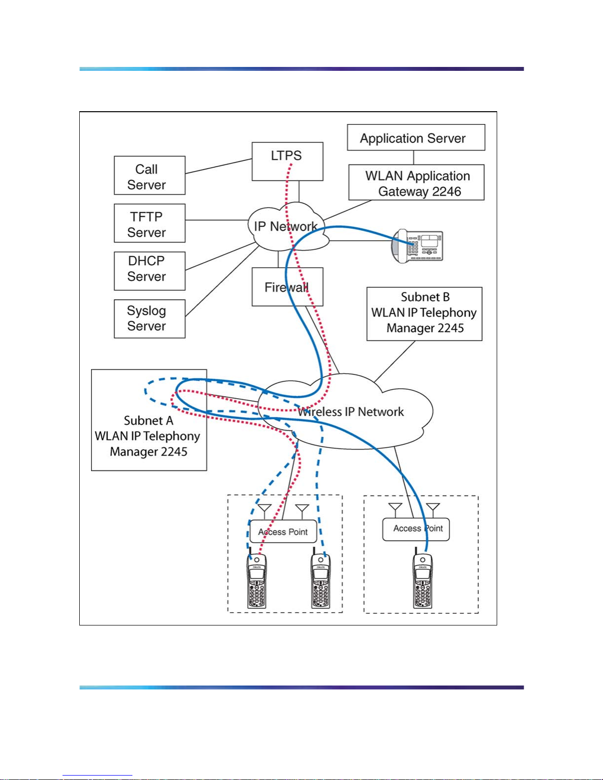
Figure 1 "Typical wireless telephone network configuration" (page 24) shows
a typical wireless telephone network configuration. The three different lines
indicate the following:
•
Red—signalling
•
Blue dashed—wireless to wireless audio
•
Blue solid—wireless to wired audio
Nortel Communication Server 1000
WLAN IP Telephony Installation and Commissioning
NN43001-504 01.02 Standard
Release 5.0 15 June 2007
Copyright © 2004-2007, Nortel Networks
.
Page 24
24 Overview
Figure 1
Typical wireless telephone network configuration
Call Server
The Call Server can be the Call Server of any Nortel Communication Server
(CS) 1000 system running CS 1000 Release 5.0 software.
Nortel Communication Server 1000
WLAN IP Telephony Installation and Commissioning
NN43001-504 01.02 Standard
Release 5.0 15 June 2007
Copyright © 2004-2007, Nortel Networks
.
Page 25

WLAN Handset 2210/2211/2212 and WLAN Handset 6120/6140 25
DHCP Server
The existing DHCP Server can be on either side of the firewall, according
to the site administrator’s preference. The DHCP server is optional if the
wireless handsets and WLAN IP Telephony Manager 2245 are statically
configured.
DHCP options
If you use a DHCP Server, configure the following options:
•
DHCP Option 3—the Default Gateway
•
DHCP Option 7—the Syslog Server
•
DHCP Option 42—the Time Server
•
DHCP Option 60—the Class Identifier
•
DHCP Option 66—the IP address of the TFTP Server
•
DHCP Option 151—the IP address of the WLAN IP Telephony Manager
2245
• DHCP Option 152—the IP address for the optional WLAN Application
Gateway 2246
For more information, see "DHCP server options" (page 184).
TFTP Server
A TFTP Server is required in an IP Telephony system to distribute software
to the wireless handsets and WLAN IP Telephony Manager 2245. It can
reside on a different subnet than the Call Server and APs. The TFTP Server
can be located on either side of the firewall.
Firewall
The firewall is an optional element that is often used to separate the wireless
and wired domains.
WLAN Handset 2210/2211/2212 and WLAN Handset 6120/6140
The WLAN Handset 2210/2211/2212 and WLAN Handset 6120/6140 uses
Voice over IP (VoIP) technology on IEEE 802.11-compliant Wireless Local
Area Networks (WLANs). Access points (AP) use radio frequencies to
transmit signals to and from the wireless handsets.
ATTENTION
In this document, handsets means the WLAN Handset 2210/2211/2212 and
WLAN Handset 6120/6140. Where the feature refers only to a specific handset,
the full handset name is used.
Nortel Communication Server 1000
WLAN IP Telephony Installation and Commissioning
NN43001-504 01.02 Standard
Release 5.0 15 June 2007
Copyright © 2004-2007, Nortel Networks
.
Page 26

26 Overview
Employees carry wireless handsets to make and receive calls as they move
throughout the building. The handsets are used only on the premises; they
are not cellular phones. The handsets communicate with the CS 1000 and
with the WLAN IP Telephony Manager 2245. Just like wired telephones, the
wireless handsets receive calls directly, receive transferred calls, transfer
calls to other extensions, and make outside and long-distance calls (subject
to corporate restrictions).
The handsets interoperate with other IP Line and IP Trunk features and
devices, such as IP Peer, and the IP Phone 20xx and IP Softphone 2050
series of IP Phones, with the exception of some media-related constraints
described in "Codecs" (page 79).
The frequencies that are allocated are governed by IEEE guidelines for
WLANs and are part of the free spectrum. The WLAN Handset 6120/6140
uses a, b, and g frequencies, and the WLAN Handset 2210/2211/2212
uses the b frequency.
The handsets work only in a Nortel Succession 3.0 (and later) environment
coordinated with a Communication Server (CS) 1000 or Business
Communications Server (BCM). These handsets communicate with the
Nortel call server through the Unified Network IP Stimulus (UNIStim)
protocol. The media path of the voice call goes from the handset directly to
the destination device (through the WLAN Telephony Manager 2245). In
addition, the handset encapsulates all traffic in the SpectraLink VoicePriority
(SVP) protocol. The WLAN Telephony Manager 2245 deencapsulates the
VoIP traffic from SVP and passes it onto the network—it does not translate
between UNIStim and SVP. Therefore, the Telephony Manager 2245 is in
the path of all communication to and from the handset. Likewise, signaling
goes from the handset to the Telephony Manager 2245 to the call server.
The WLAN Handset 2211 and the WLAN Handset 6140 are the most
durable and they are the only handsets that support Push-to-talk (PTT).
For more information about the handsets, see the following publications:
•
WLAN Handset 2210 User Guide (NN10300-077)
•
WLAN Handset 2211 User Guide (NN10300-078)
•
WLAN Handset 2212 User Guide (NN10300-071)
•
WLAN Handset 6120 User Guide (NN43150-100)
•
WLAN Handsets Fundamentals (NN43001-505)
Components
The WLAN Handset Series 2200 offers the following components for local
configuration:
•
Nortel WLAN Handset 2200 Series Configuration Cradle
Software—software only
Nortel Communication Server 1000
WLAN IP Telephony Installation and Commissioning
NN43001-504 01.02 Standard
Release 5.0 15 June 2007
Copyright © 2004-2007, Nortel Networks
.
Page 27

WLAN Handset 2210/2211/2212 and WLAN Handset 6120/6140 27
•
Nortel WLAN Handset 2200 Series Configuration Cradle—required
hardware (serial cable included)
The WLAN Handset 6100 Series offers the following components for local
configuration:
•
Nortel WLAN Handset 6100 Series Administration Tool
Software—software only
•
Nortel WLAN Handset6100 Series Dual Slot Handset Charger—required
hardware (USB cable not included)
•
USB Cable for the Nortel WLAN Handset 6100 Series Dual Slot Handset
Charger
ATTENTION
For the purposes of this document
•
Configuration Cradle refers to the Nortel WLAN Handset 2200 Series
Configuration Cradle.
•
Handset Administration Tool refers to the Nortel WLAN Handset 6100
Series Administration Tool Software.
•
Dual Slot Handset Charger or Handset Charger refers to the Nortel
WLAN Handset 6100 Series Dual Slot Handset Charger.
Language
The handset menus and screens that originate from the Call Server
are displayed in the languages supported on the Call Server. The
administration and configuration menus, and all other local handset prompts
are English-only.
Licenses
The handset appears to the Call Server as a standard IP Phone 2004.
Therefore, each wireless handset requires one IP User License and is
subject to the same feature packaging requirements as the existing IP
Phone 2004.
Wi-Fi Multimedia
The handsets support basic Wi-Fi Multimedia (WMM) to improve Quality
of Service (QoS), as defined in the 802.11e specification. WMM provides
prioritized QoS capability when concurrent applications, each with unique
latency requirements, are competing for network resources.
Nortel Communication Server 1000
WLAN IP Telephony Installation and Commissioning
NN43001-504 01.02 Standard
Release 5.0 15 June 2007
Copyright © 2004-2007, Nortel Networks
.
Page 28

28 Overview
When WMM is used, all voice traffic originating from the wireless handset is
assigned the WMM Voice Access Category, making it the highest priority
application. If the wireless network supports WMM, the handsets enable
WMM support automatically; otherwise, SpectraLink Voice Prioritization
(SVP) is used.
Wired Equivalent Privacy
The handsets support Wired Equivalent Privacy (WEP) as defined by the
802.11a, b, and g specification. Nortel offers the product with both 40-bit
and 128-bit encryption. WEP increases the security of the wireless LAN to a
level similar to a wired Ethernet LAN.
Wi-Fi Protected Access
The handsets support Wi-Fi Protected Access (WPA) using preshared key
(PSK), as defined by the 802.11i specification. WPA increases the security
of the wireless LAN, using key encryption, key rotation, authentication and
message integrity checking.
Wi-Fi Protected Access2
The handsets support Wi-Fi Protected Access2 (WPA2) using preshared
key (PSK) and Advanced Encryption Standard (AES), as defined by the
802.11i specification. WPA2 increases the security of the wireless LAN,
using key encryption, key rotation, data encryption, authentication, and
message integrity checking.
Virtual Private Network
The WLAN Handset 2212 supports Virtual Private Network (VPN) security.
VPN security provides a secure tunnel for the transfer of unencrypted
information. A two-phase approach is used to negotiate the tunnel, with
Phase 1 protecting Phase 2. Phase 1 uses preshared keys, Diffie-Hellman
group, hashing, and encryption. Phase 2 uses hashing and encryption.
Both phases have limited, configurable lifetimes.
Push-to-talk feature
With the Push-to-talk (PTT) feature, the WLAN Handset 2211 and the
WLAN Handset 6140 can operate in a PTT group-broadcast mode like a
two-way radio, in addition to the standard telephone operation.
For more information, see WLAN Handsets Fundamentals (NN43001-505).
Text-messaging feature
All WLAN handsets support text messaging applications through the WLAN
Application Gateway 2246. The application server communicates to the
WLAN Application Gateway 2246 through a proprietary Open Application
Nortel Communication Server 1000
WLAN IP Telephony Installation and Commissioning
NN43001-504 01.02 Standard
Release 5.0 15 June 2007
Copyright © 2004-2007, Nortel Networks
.
Page 29

WLAN IP Telephony Manager 2245 29
Interface (OAI) messaging protocol. The WLAN Application Gateway
2246 forwards the messages to the WLAN IP Telephony Manager, which
encapsulates the message for delivery to the handset.
If text-messaging functions are programmed, the handset can receive text
messages. While you access text messages, the handset is in messaging
mode. Incoming calls ring with the second call-ringing sound.
Loud noise environments
The handsets are designed to provide optimal voice quality. However, when
used in extremely loud noise environments, (for example, close to working
heavy machinery), degradation in call quality can be experienced due to
echo. Avoid using the handsets in loud noise environments.
WLAN IP Telephony Manager 2245
The WLAN IP Telephony Manager 2245 is a device that manages IP
telephony network traffic on the WLAN system. It is required to utilize the
11Mbs maximum transmission speed available in the handsets. The WLAN
IP Telephony Manager 2245 acts as a proxy for the wireless handsets. It
provides a number of services including a QoS mechanism, AP bandwidth
management, and efficient RF link utilization.
The WLAN IP Telephony Manager 2245 works with the APs to provide
Quality of Service (QoS) on the WLAN. All voice packets are encapsulated
by the wireless handsets. The encapsulated voice packets to and from the
wireless handsets are handled by the WLAN IP Telephony Manager 2245
and routed to and from a Call Server.
SpectraLink Voice Priority (SVP) is the QoS mechanism implemented on
the wireless handsets and APs to enhance voice quality over the wireless
network. SVP gives preference to voice packets over data packets on
the wireless medium, increasing the probability that all voice packets are
transmitted and with minimum delay. SVP is fully compliant with the IEEE
802.11 and 802.11a, b, and g standards.
Each subnet, where the wireless handsets operate, requires at least one
WLAN IP Telephony Manager 2245. One standalone unit can process up to
80 simultaneous calls depending on the model, as listed in Table 2 "WLAN
Nortel Communication Server 1000
WLAN IP Telephony Installation and Commissioning
NN43001-504 01.02 Standard
Release 5.0 15 June 2007
Copyright © 2004-2007, Nortel Networks
.
Page 30

30 Overview
Telephony Manager 2245 model numbers and capacities" (page 30).If
greater capacity is required, multiple units can be used in a master-slave
arrangement.
Table 2
WLAN Telephony Manager 2245 model numbers and capacities
Model number Maximum
number users
NTTQ60BA 10 simultaneous users
NTTQ60CA 20 simultaneous users
NTTQ60AA 80 simultaneous users (standard)
WLAN Application Gateway 2246
The WLAN Application Gateway 2246 is an optional device that enables
third-party applications to communicate directly with up to 10 000 wireless
handsets. The WLAN Application Gateway 2246 is connected to the LAN
Ethernet switch through an RJ-45CAT5 cable.
For more information about the WLAN Application Gateway 2246, see
Appendix "WLAN Application Gateway 2246" (page 147).
A WLAN Application Gateway 2246 supports 64 to 10 000 wireless
handsets, depending on the model of Gateway, as listed in Table 3 "WLAN
Application Gateway 2246 models and capacities" (page 30).
Table 3
WLAN Application Gateway 2246 models and capacities
Model number
Maximum
number of users
NTTQ65AA
64
NTTQ65BA
128
NTTQ65CA
256
NTTQ65DA
512
NTTQ65EA
1024
NTTQ65FA
10 000
Access Points
802.11a, b, and g APs provide the connection between the wired Ethernet
LAN and the wireless (802.11) LAN. APs must be positioned in all areas
where the wireless handsets are used. The number and placement of APs
Nortel Communication Server 1000
WLAN IP Telephony Installation and Commissioning
NN43001-504 01.02 Standard
Release 5.0 15 June 2007
Copyright © 2004-2007, Nortel Networks
.
Page 31

Handset switchover 31
affect the coverage area and capacity of the wireless system. Typically,
the requirements for use of handsets are similar to that of other wireless
data devices.
The APs must be either SVP-compliant or WMM-compliant to support QoS.
For a list of supported APs, see Appendix "Compatible Access Points"
(page 223).
Handset switchover
When a user on an active call is moving about, the call switches from AP to
AP in the subnet. This changeover is transparent to the user.
Loss of signal
If a wireless handset is out of range of all APs, it waits 20 seconds for a
signal to return. If a signal is not reacquired within 20 seconds, the wireless
handset loses connection to the Call Server and any calls are dropped.
When the wireless handset comes back into range of an AP, it reestablishes
a connection to the Call Server and goes through the system registration
process.
Note: If a wireless handset is out of contact with the system for
four seconds (worst case scenario) when the UNIStim messaging is
occurring, a UNIStim failure could result, causing the wireless handset
to lose the UNIStim association with the Line Telephony Proxy Server
(LTPS).
Handset switchover
If a user on an active call is moving about, the call switches from AP to AP
in the subnet. This changeover is transparent to the user.
Loss of signal
If a wireless handset is out of range of all APs, it waits 20 seconds for a
signal to return. If a signal is not reacquired within 20 seconds, the wireless
handset loses connection to the Call Server and any calls are dropped.
When the wireless handset comes back into range of an AP, it reestablishes
a connection to the Call Server and goes through the system registration
process.
ATTENTION
If a wireless handset is out of contact with the system for four seconds (worst case
scenario) during UNIStim messaging, a UNIStim failure could occur and cause
the wireless handset to lose the UNIStim association with the Line Telephony
Proxy Server (LTPS).
Nortel Communication Server 1000
WLAN IP Telephony Installation and Commissioning
NN43001-504 01.02 Standard
Release 5.0 15 June 2007
Copyright © 2004-2007, Nortel Networks
.
Page 32

32 Overview
Nortel Communication Server 1000
WLAN IP Telephony Installation and Commissioning
NN43001-504 01.02 Standard
Release 5.0 15 June 2007
Copyright © 2004-2007, Nortel Networks
.
Page 33

33
Planning
This chapter contains information about the following topics:
•
"Challenges of integrating voice applications" (page 33)
•
"DHCP server planning" (page 36)
•
"TFTP Server planning" (page 38)
•
"Syslog Server planning" (page 40)
•
"Access point planning" (page 40)
•
"Network planning" (page 46)
•
"Network recommendation" (page 46)
•
"Network management" (page 47)
•
"Zones" (page 54)
•
"Other network design considerations" (page 55)
• "WLAN IP Telephony Manager 2245 planning" (page 59)
•
"Multicast" (page 65)
•
"Placement guidelines for the WLAN IP Telephony Manager 2245"
(page 65)
•
"WLAN Application Gateway 2246 planning" (page 73)
•
"WLAN IP Telephony Manager 2245 and WLAN Application Gateway
2246 installation requirements" (page 74)
•
"IP address planning" (page 74)
•
"Planning worksheets" (page 75)
Challenges of integrating voice applications
The integration of voice applications on any data network causes some
challenges. WLANs create a number of problems for voice, above and
beyond those inherent to most data networks, such as:
•
high overhead of 802.11
Nortel Communication Server 1000
WLAN IP Telephony Installation and Commissioning
NN43001-504 01.02 Standard
Release 5.0 15 June 2007
Copyright © 2004-2007, Nortel Networks
.
Page 34

34 Planning
•
rate scaling and variable capacity
•
power adjustments and variable capacity
•
Quality of Service (QoS)
High overhead of 802.11
Unlike many other 802.n standards, 802.11 has a very high amount of
overhead associated with transmitting a packet. To compare an 802.3
network with an 802.11 network, the difference in overhead for transmitting
line-rate minimum frame sizes compared to the line-rate maximum frame
sizes on an 802.3 network can be significant, yet not nearly as significant as
on an 802.11 network.
For 802.11, the difference in effective throughput varies dramatically with
packet size because of the amount of overhead involved in transmitting
a frame. Therefore, the effective throughput of the medium is potentially
higher for data clients that use very large packet sizes than it is for voice
clients that use smaller packets. As an example, using very conservative
assumptions for average frame size, no rate scaling, and no contention or
collisions, transmission overhead consumes as much as 67% of the total
802.11 medium capacity. By contrast, in an 802.3 network using the same
assumptions, the overhead is about 8%.
Rate scaling and variable capacity
802.11b supports four transmission rates or data rates. Usually, as a
handset gets farther from an Access Point (AP), both devices scale down to
lower transmission rates to compensate for a weaker signal. As a result,
a transmission at the 5.5 megabits per second (Mb/s) data rate takes
approximately twice as long as the same size packet transmitted at the 11
Mb/s data rate. Longer transmission times mean less transmission time for
other handsets. Therefore, rate scaling compromises the overall throughput
of the medium.
Rate scaling is necessary to extend the coverage of the AP beyond a very
tight region around the AP, but the effects must be taken into account when
determining medium capacity. For example, if the maximum call capacity for
an AP is 12 when all handsets are using the 11 Mb/s physical (PHY) layer,
two handsets scaling down to 5.5 Mb/s as they move away from the AP
reduces the total call capacity of that AP to roughly 10. This factor makes
engineering the number of APs for the network difficult, because handsets
are roaming around and rate scaling up and down as necessary. Handsets
are moving, and as they do, the engineering target of call capacity becomes
a moving target.
Nortel Communication Server 1000
WLAN IP Telephony Installation and Commissioning
NN43001-504 01.02 Standard
Release 5.0 15 June 2007
Copyright © 2004-2007, Nortel Networks
.
Page 35

Challenges of integrating voice applications 35
Power adjustments and variable capacity
A WLAN has dynamic mechanisms in place for adjusting channels,
adjusting power, and filling coverage holes, all in response to changes in
the Radio Frequency (RF) environment. All of these mechanisms present
challenges to the engineering of voice networks.
Dynamic adjustments work well for guaranteeing minimum coverage and
connectivity of devices, particularly data devices. Voice requires more
planned engineering.
Usually, the number of calls per area (square foot) and calls per AP
determines the number of APs required to support the voice applications
and devices. Power adjustments affect these parameters. Ifan AP increases
power, it provides coverage for a larger area, meaning a greater call demand
for the AP. Doubling the power of an AP can quadruple its coverage area,
which means up to four times as much call demand as originally engineered.
That increased coverage area also has substantial portions of lower data
rate coverage. In addition, the added cochannel interference to other cells
using the same channel degrades their call capacity. The net effect is that
a network previously tuned for voice is now less capable of meeting the
demands of voice than it was before the dynamic power adjustment.
Automatic RF changes do not always have a negative impact on
voice-engineered networks. Admission control techniques help with the
oversubscription problems related to increasing cell sizes dynamically. Hole
filling, after an AP failure occurs, also provides substantial value to a voice
solution.
When VoWLAN drives the engineering of the network both in scale and
capacity, sometimes automatic RF features create more challenges than
they resolve.
Quality of Service
802.11 is a shared media technology, but only one device can use the
media at a time. The AP abides by this rule as well.
Because the transmitting device cannot detect collisions, 802.11 uses a
statistical mechanism to reduce the possibility of collisions when two devices
are ready to transmit at the same time. After the medium becomes available,
the mechanism requires the devices to wait a random amount of time before
starting transmission. Because of this simple mechanism, a nonvoice
device is as equally as likely to be allowed to transmit as a voice device is.
Nortel Communication Server 1000
WLAN IP Telephony Installation and Commissioning
NN43001-504 01.02 Standard
Release 5.0 15 June 2007
Copyright © 2004-2007, Nortel Networks
.
Page 36

36 Planning
For example, if a data device does seize the medium, it can send a
1500-byte frame at the lowest data rate (if it is far away from the AP), and
further delay voice frames. In addition, several data devices contending for
the medium can each, in turn, send large frames before the voice device
gained access to the medium.
Without a way to give preferential transmission opportunities to voice
devices, supporting voice applications is a tremendous challenge on 802.11
WLANs. SpectraLink Voice Priority (SVP) has evolved into a de facto
standard for Quality of Service (QoS) and serves as a model to illustrate the
functions that a successful QoS mechanism can implement.
The 802.11e standard ultimately resolves QoS issues, but the delays in the
standard create a number of additional implementation-specific challenges.
Wi-Fi Multimedia (WMM) is a step toward full 802.11e compliance for voice
and multimedia, but it is not a solution. Because it is a step, QoS feature
evolution must progress towards better and more solid standards-based
QoS capabilities.
WMM refines 802.11 to give statistical preference to certain classes over
other classes. It is fully backward-compatible to legacy non-WMM devices,
which function just like WMM best-effort class devices.
DHCP server planning
The handset IP-related parameters can be configured manually or through
a DHCP server (RFC 1541 and RFC 1533). Any DHCP server can be used,
but it must support the following capabilities.
• Provide Client IP address
•
DHCP Option 1—Subnet Mask
•
DHCP Option 3—Default Gateway
•
DHCP Option 60—Class Identifier. The wireless handsets use the Class
Identifier of Nortel-221x-A or Nortel-61xx-A. The DHCP server can use
the string in the Class Identifier to uniquely identify a wireless handset.
•
DHCP Option 66. This can be used to specify the address of the TFTP
Server. If this option is not configured, the wireless handset looks at the
Next server Boot server (siaddr) Option for the address of the TFTP
Server* Vendor Specific Option 43, 128, 144, 157, 191, or 251. Only
one of these options is required. The DHCP server encodes the Server
1 information using the same format as the IP Phone 2004. If the Server
2 information is also present in the option, it is ignored.
•
DHCP Option 151. This option contains the IP address of the WLAN IP
Telephony Manager 2245. If Option 151 is not configured, the wireless
Nortel Communication Server 1000
WLAN IP Telephony Installation and Commissioning
NN43001-504 01.02 Standard
Release 5.0 15 June 2007
Copyright © 2004-2007, Nortel Networks
.
Page 37

DHCP server planning 37
handset performs a DNS lookup of the name SLNKSVP2, if Options 6
(DNS Server) and 15 (Domain Name) are configured.
•
DHCP Option 152. If an optional WLAN Application Gateway 2246 is
used in the system, its IP address can be specified with this option.
Each wireless handset effectively uses two IP addresses in the wireless
subnet: one for the physical wireless handset and a second alias IP address
that is used on the WLAN IP Telephony Manager 2245. When allocating
addresses in a subnet scope on the DHCP server, a contiguous block of IP
addresses as large as the number of wireless handsets supported must be
marked as unavailable for distribution for other uses by the DHCP server.
When multiple WLANs are connected to a single Nortel Wireless Security
Switch (WSS), the DHCP server can require specific configuration
modifications. For a specific WSS that is used for special DHCP
configuration requirements, see the WSS documentation.
The WLAN handsets support numerous DHCP extensions for assigning
various configuration options. The WLAN handsets supply a vendor class
identifier string, which in this case is Nortel-221x-A and Nortel-61xx-A.
The WLAN handsets do not accept these options from the DHCP server
encapsulated in a 43 Vendor Type option (which is the normal way vendor
classes work). Consequently, you do not define these options as part of a
vendor class on the DHCP server. Instead, you define them as new options
that are assigned using the native code numbers that you give them.
The WLAN handsets specifically request a list of options in the DISCOVER
message. The list of options (aside from the IP address and subnet mask)
needed by a WLAN handset is:
• Class Identifier (60)
•
TFTP Server (66)
•
Signaling Server Address and other parameters (43, 128, 144, 157,
191, or 251)
•
WLAN IP Telephony Manager 2245 Address (151)
•
WLAN Application Gateway 2246 Address (152)
For an example, see Figure 2 "Sample DHCP reservation showing assigned
parameters" (page 38).
Nortel Communication Server 1000
WLAN IP Telephony Installation and Commissioning
NN43001-504 01.02 Standard
Release 5.0 15 June 2007
Copyright © 2004-2007, Nortel Networks
.
Page 38

38 Planning
Figure 2
Sample DHCP reservation showing assigned parameters
Another use for the DHCP server is to make code upgrades to the handset
easier. To prevent handsets from checking for code upgrades, assign the
value of 255.255.255.255 for the TFTP server address.
A problem can arise for handset users who travel. For example, the
company employing the handset solution is a retailer with many stores.
Each store has a local call server for the local employees who use various
VoIP devices, so all the attributes are defined at the scope level. What
happens if supervisors, who travel from store to store, want to use their
handsets at each location? The supervisors can be assigned to a signaling
server that does not recognize their phones. The best way to support these
users is to create unique reservations in each remote scope for each user’s
WLAN handset and specify the proper signaling server. This solution can
be cumbersome if there are a large number of users who travel.
TFTP Server planning
A TFTP Server (RFC1350) holds the software images for updating the
handsets and the WLAN IP Telephony Manager 2245. After the IP address
of the TFTP server is configured on a wireless handset, each time the
wireless handset is powered on, the wireless handset checks its version of
firmware against the firmware on the TFTP Server, and if the version is
different, the wireless handset downloads the new firmware from the TFTP
Server. Similarly, when a WLAN IP Telephony Manager 2245 reboots, or
is manually reset by the operator, it checks its version of software against
the version on the TFTP Server. If the versions are different, the WLAN IP
Telephony Manager 2245 downloads the new software.
The WLAN Handsets 2210/2211/2212 and WLAN Handsets 6120/6140
share the same configuration file that provides firmware version information
for the TFTP process. The actual software files are specific to either the
WLAN Handset 2200 series or the WLAN Handset 6100 series. At an
installation, which uses both the WLAN Handsets 2210/2211/2212 and the
WLAN Handsets 6120/6140, the software files for both handset series must
be installed and available on the TFTP server for the site.
Nortel Communication Server 1000
WLAN IP Telephony Installation and Commissioning
NN43001-504 01.02 Standard
Release 5.0 15 June 2007
Copyright © 2004-2007, Nortel Networks
.
Page 39

TFTP Server planning 39
Only one TFTP server is needed in the network, and it need not be
colocated with the handsets or the WLAN IP Telephony Manager 2245.
There is a client-dependent aspect to how the handsets function with the
TFTP server. How well a server works with the handsets can vary between
code versions on the handset.
You can configure handsets to not contact the TFTP server upon boot up, by
configuring 255.255.255.255 as the IP address for the TFTP server (either
directly in the handset or through the DHCP option). You can configure
the WLAN IP Telephony Manager 2245 to not contact the TFTP server by
changing the TFTP server address to none in the configuration.
The following information must be considered when planning for a TFTP
Server:
•
The process for the wireless handset to check its version of firmware
against what is available on the TFTP Server takes less than two
seconds on a quiet network.
•
If the TFTP Server is offline or unreachable, the wireless handset tries
for about 10 seconds before giving up and using its existing version
of firmware.
•
The wireless handset firmware downloading process takes about 30
seconds.
•
The TFTP Server must be capable of supporting multiple TFTP sessions.
•
When a wireless handset makes a TFTP request, it uses file names
without a full path name. Therefore, software updates for the WLAN IP
Telephony Manager 2245 and handsets must be installed into the root
directory of the TFTP Server.
When the software files are uploaded to the TFTP server. they must be
unzipped. Allow time for the TFTP server to refresh and be aware of the files
before attempting to download software to the wireless handsets and WLAN
IP Telephony Manager 2245. Monitor the TFTP Server for any errors.
The TFTP Server can be located anywhere on the network if the wireless
handsets have the subnet mask and default IP gateway configured correctly.
However, the wireless handset expects a response within two seconds to
any TFTP request. Therefore, the TFTP Server must not be located, for
example, at the other end of a slow WAN link.
If too many wireless handsets are attempting to download new software
simultaneously, the downloads can slow down or return error messages. To
reduce the number of retries and error messages, manage the download
process by staggering the times the wireless handsets download the
software.
Nortel Communication Server 1000
WLAN IP Telephony Installation and Commissioning
NN43001-504 01.02 Standard
Release 5.0 15 June 2007
Copyright © 2004-2007, Nortel Networks
.
Page 40

40 Planning
Nortel has tested the following TFTP servers. They are listed in order of
preference.
•
Nortel TFTP server (ONMS application)
•
3COM TFTP
•
PumpkinTFTP
Syslog Server planning
A Syslog Server listens for incoming syslog messages on UDP port 514 and
then processes the messages according to local administrative procedures.
Usually the syslog messages are logged for subsequent review by the
system operator. A number of devices used within a handset wireless
configuration are capable of sending messages to a Syslog Server.
The Syslog Server can be any RFC 3164-compliant log server. You can
configure the WLAN IP Telephony Manager 2245, WLAN Application
Gateway 2246, WLAN APs 2220/2221/2230/2231, and the WLAN Handsets
2210/2211/2212/6120/6140 to generate syslog messages. For information
about configuring syslog messages, see the documentation for the Wireless
Security Switches and WLAN APs. For information about configuring syslog
messages on the WLAN IP Telephony Manager 2245, see "Configure the
network" (page 103).
There are numerous third-party Syslog Servers available. You can use any
RFC 3164-compliant Syslog Server.
Access point planning
APs utilize radio frequencies to transmit signals to and from the wireless
handsets.
It is essential to know where to install the APs to provide effective coverage
for wireless handset use. It is necessary to verify that coverage is available
where it is needed. The first step is to define exactly where the coverage is
needed, which requires a site survey.
Recommendation
A site survey must be performed before installing a wireless LAN. A site survey
is also recommended when an existing network structure is modified or when
physical changes are made to a site.
Nortel recommends the use of the Nortel Site Survey Tool to perform the site
survey.
Nortel Communication Server 1000
WLAN IP Telephony Installation and Commissioning
NN43001-504 01.02 Standard
Release 5.0 15 June 2007
Copyright © 2004-2007, Nortel Networks
.
Page 41

Access point planning 41
A site survey is critical to designing and implementing a wireless LAN. The
site survey is used to determine the number of APs needed to support the
wireless handset users and to determine the best placement of the APs.
Different AP vendors provide different tools to do this.
Site survey
To conduct a site survey, set up an AP at a particular location. Use a
computer equipped with a wireless LAN device and site survey software
or a handset operating in Site Survey mode to measure the strength of
the signal from the AP. Move the wireless device around and repeat the
measurements to determine the optimum number and best locations for
the APs. This method helps identify dead zones and areas where building
materials or other factors affect the performance of the network.
Site Survey mode
The handset Site Survey mode displays negative dBm levels. These levels
represent the strength of the received signal (Received Signal Strength
Indication or RSSI) from an AP. The RSSI information aids in determining if
WLAN coverage is adequate.
For information about using the Site Survey mode, see WLAN Handsets
Fundamentals (NN43001-505).
Note: The handsets do not require connectivity to a 2245 IP Telephony
Manager or the Call Server to enable the Site Survey mode to be
used. The minimum configuration required is the Extended Service
Set Identifier (ESSID) of the WLAN or test AP and the WEP keys, if
applicable.
Access point requirement considerations for b radio
Each site is unique in its AP requirements. Consider the following points
when determining how many APs are needed and where to place them:
•
Minimum Radio Signal Strength—All APs in the coverage area must
receive a signal strength better than -70dBm. Measurement is made in
negative dBm, which measure the amount of signal loss due to distance.
Therefore, stronger signals are those with smaller values. For example,
-50 and -60 indicate stronger signals than -70; -80 is a weaker, poorer
signal than -70.
•
Adjacent APs and channel interference—In order to avoid undesirable
interference from adjacent APs, ensure that adjacent APs do not use
channels that overlap on the same frequencies.
For more information, see Figure 3 "Frequencies used by b radio" (page
42). In the figure, channels on the same horizontal line do not overlap.
In the coverage area of any given AP, signals from other APs using
overlapping channels must be at least -15 to -20dBm weaker. Because
Nortel Communication Server 1000
WLAN IP Telephony Installation and Commissioning
NN43001-504 01.02 Standard
Release 5.0 15 June 2007
Copyright © 2004-2007, Nortel Networks
.
Page 42

42 Planning
the Site Survey mode displays signals only from APs on the same
Extended Service Set ID (ESSID), check for signals from APs using all
ESSIDs to avoid channel overlap.
Figure 3
Frequencies used by b radio
•
Wireless handset range—Wireless LAN coverage must be available
wherever wireless handsets are used. Although the typical range
for a wireless handset is comparable to that of a laptop computer
utilizing a wireless LAN PC Card, the range can not be exactly the
same. Therefore, it is preferable to use a handset to carry out the site
survey, if possible. Remember that wireless handsets might be used in
areas where data devices are not typically used, such as stairwells,
washrooms, hallways, and outdoor areas.
• Number of wireless handsets per AP—Estimate the number of wireless
handsets and the anticipated call volume per AP area to ensure that the
maximum number of calls per AP is not exceeded. For the maximum
number of calls per AP for each supported manufacturer, see Appendix
"Compatible Access Points" (page 223).
•
The data rates at which the wireless handsets operate—Higher data
rates (such as 11Mbs) can only be sustained while well within the range
of the AP. If the wireless handsets are operating near the limits of the
radio frequency (RF) coverage from the AP, they automatically drop
to 1 Mbs operation.
handsets require approximately:
— 7% of available bandwidth per call at 11 Mbs operation
— 10% of the available bandwidth per call for 2 Mbs operation
Nortel Communication Server 1000
WLAN IP Telephony Installation and Commissioning
NN43001-504 01.02 Standard
Release 5.0 15 June 2007
Copyright © 2004-2007, Nortel Networks
.
Page 43

Access point planning 43
— 15% of the available bandwidth per call for 1 Mbs operation.
Note: These requirements mean that areas with a high-use density
must receive RF coverage at the highest data rate of operation.
•
LAN bandwidth—Estimate anticipated peak call volume to ensure that
enough bandwidth is available to handle the network traffic generated
by all the wireless handsets. Handsets require approximately 150 kbps
of bandwidth per call. Network traffic can be monitored and analyzed
using a network sniffer or an SNMP workstation.
•
Number of other wireless devices per AP—The wireless handsets can
share bandwidth with other wireless devices. To ensure adequate RF
bandwidth availability, consider the number of wireless data devices in
use per AP.
Note: In a very large or complex site, it can be advisable to contract
a professional site survey.
Effective site survey
Consider the following points for an effective site survey.
Network usage
Examine the network usage:
•
How many people use a wireless handset?
•
What areas of the site require wireless handset access?
•
How many hours each day are wireless handsets typically in use?
•
Which locations are likely to generate the largest amount of traffic?
•
Where is future network expansion most likely?
Mobility requirements
Assess the mobility requirements:
•
How many wireless handset users are in motion continually, such as in
a warehouse or hospital?
•
How many users work from different fixed locations throughout the site?
Physical site study
Perform a study of the physical site:
•
Study blueprints of the proposed site. A site blueprint provides a map of
the site, including the location of objects such as walls, partitions, and
anything else that could affect the performance of a wireless handset.
This helps identify areas where wireless handsets are less likely to
perform well. Many obstructions are not readily visible and, in some
Nortel Communication Server 1000
WLAN IP Telephony Installation and Commissioning
NN43001-504 01.02 Standard
Release 5.0 15 June 2007
Copyright © 2004-2007, Nortel Networks
.
Page 44

44 Planning
cases, a room originally built for a specific purpose, such as a radiology
lab, can be converted into something completely different, such as a
conference room. The blueprint can also show areas proposed for
future building expansion.
•
Mark possible wireless handset usage locations on the blueprint and
refer to the marked blueprint during the physical walk-through and
inventory.
Walk-through and survey
Conduct a physical walk-through and survey:
•
Document any items or materials near a proposed AP location that might
interfere with reception or transmission and affect wireless handset
performance, such as metal shelving.
•
Document stock and inventory levels, current environmental conditions,
and any materials that can interfere with wireless handset transmissions.
•
Walk around the site with a site survey tool before installing APs.
Use two portable computers with wireless hardware operating on a
point-to-point basis. Using diagnostic software provided by the AP
vendor, a coverage area for a potential AP can be determined by
keeping one portable computer in one place and moving around with the
other computer. Check with the vendor as to what tools are provided
and what approach is recommended for deploying their APs.
RF transmission testing
After the APs are installed and configured, measure the strength of the
Radio Frequency (RF) transmissions. Signal strength testing ensures that all
usage areas have adequate coverage. This can be performed in two ways.
1. Use the handsets to determine AP signal strength using the Site Survey
mode.
2. Use two portable computers with wireless hardware operating on a
point-to-point basis. Using diagnostic software provided by the AP
vendor, a coverage area for a potential AP can be determined by
keeping one portable computer in one place and moving around with the
other computer. Check with the vendor as to which tools are provided
and which approach is recommended for deploying their APs.
Adjust the APs as needed.
Example of AP placement
Figure 4 "Sample AP placement diagram for b radio" (page 45) is an
example of an AP placement diagram based on the results of a site survey.
Nortel Communication Server 1000
WLAN IP Telephony Installation and Commissioning
NN43001-504 01.02 Standard
Release 5.0 15 June 2007
Copyright © 2004-2007, Nortel Networks
.
Page 45

Access point planning 45
Figure 4
Sample AP placement diagram for b radio
Solving coverage issues
To resolve coverage issues, add and relocate APs.
Solving overlap issues
To resolve overlap issues, reassign channels to the APs or relocate the
APs. Like channels require 15–20dBm separation. See Figure 5 "b radio
assignment" (page 46).
Nortel Communication Server 1000
WLAN IP Telephony Installation and Commissioning
NN43001-504 01.02 Standard
Release 5.0 15 June 2007
Copyright © 2004-2007, Nortel Networks
.
Page 46

46 Planning
Figure 5
b radio assignment
For more information about overlap, see the AP vendor documentation.
Network planning
You must ensure that all connections and interfaces for the IP Telephony
network are configured as full-duplex. Duplex mismatches anywhere on the
WLAN can cause the wireless IP Telephony system not to function normally.
Network recommendation
To maximize security and to minimize accessibility for unnecessary traffic
to reach the WLAN Handsets, Nortel recommends that you adopt the
following measures:
•
Create a separate VLAN for voice traffic and map the handsets to this
VLAN to mask the handsets from other devices on the network.
•
Implement Access Control Lists (ACLs) on the WLAN infrastructure to
contain the handsets but deny other traffic.
— The WLAN IP Telephony 2245 uses IP protocol 119 and
encapsulates both signalling and media (RTP) into a common packet
format allowing the access points to prioritize legitimate handset
traffic.
Nortel Communication Server 1000
WLAN IP Telephony Installation and Commissioning
NN43001-504 01.02 Standard
Release 5.0 15 June 2007
Copyright © 2004-2007, Nortel Networks
.
Page 47

Network management 47
— Necessary traffic for instance DHCP must be allowed, while all other
traffic is denied.
Sample Access Control List
The following is a sample ACL for a voice VLAN named VLAN120.
set security acl ip SpectraLink permit udp 0.0.0.0
255.255.255.255
eq 68 0.0.0.0 255.255.255.255 eq 67
set security acl ip SpectraLink permit udp 0.0.0.0
255.255.255.255
eq 67 0.0.0.0 255.255.255.255 eq 68
set security acl ip SpectraLink permit cos 6 udp 0.0.0.0
255.255.255.255 0.0.0.0 255.255.255.255 eq 69
set security acl ip SpectraLink permit cos 7 119 0.0.0.0
255.255.255.255 0.0.0.0 255.255.255.255
set security acl ip SpectraLink deny 0.0.0.0 255.255.255.255
commit security acl SpectraLink
set security acl map SpectraLink vlan VLAN120 in
set security acl map SpectraLink vlan VLAN120 out
Network management
Network management is as much strategy and process as it is applications.
Managing a converged network consists of four key phases:
1
Assessment—Network Health Checks and WLAN Site Surveys
(post-deployment) are critical assessment items. The main goal is to
verify the ability of the network to provide voice at the required Quality
of Experience (QoE).
2
Predeployment—Before you deploy VoIP handsets, make the network
ready by rolling-out QoS across the network. This phase assumes the
WLAN itself is already deployed.
3
Ongoing monitoring—Regularly monitor the performance of the
converged network to ensure that voice quality continues to meet
expectations as the network grows and evolves over time.
4
Reporting and planning—Keep track of exceptions and problems and
form plans to resolve issues. The resolution of problems takes you
back through the assessment, predeployment (QoS configuration), and
monitoring phases again.
Nortel ties this business cycle together seamlessly with a set of products
that provide a comprehensive solution. This solution is comprised of
integrated and innovative standards-based technologies, such as Real
Time Control Protocol Extended Reports (RTCP-XR) for detailed real-time
management of calls in progress. The overall solution is referred to as
Proactive Voice Quality Management (PVQM).
Nortel Communication Server 1000
WLAN IP Telephony Installation and Commissioning
NN43001-504 01.02 Standard
Release 5.0 15 June 2007
Copyright © 2004-2007, Nortel Networks
.
Page 48

48 Planning
Assessment through a WLAN site survey
Technical support for VoWLAN is contingent on customers performing a
site survey of the WLAN. Currently, Nortel recommends the use of the
Ekahau Site Survey tool to verify the network deployment, although other
site survey tools are acceptable. The Ekahau product runs on a PC and
uses a WLAN network interface card (NIC) to collect data for analysis. The
output of the tool is a number of robust visualizations of the network. The
software verifies the basic coverage of the network and provides a number
of visualizations that are useful for VoWLAN deployments.
Perform capacity planning using the data rate analysis view, which shows a
color-coded view of the maximum data rate across all APs in the network.
With this view, you can see where your handsets can use the 11 Mb/s data
rate as opposed to scaling down to lower rates. Planning based on data rate
can have a big impact on voice-call-capacity planning.
Predict AP selection and roaming using the strongest AP view. This view
shows the AP with the strongest signal for each location in the building
and uses color codes for each AP. With the AP view, you can predict the
APs that are likely to be the primary choice of voice devices to use given
their location. You can also predict where the handoff to another AP (and
which AP) can occur for a moving user.
Perform resiliency planning through the AP reachability view. This view
presents a color-coded visualization of the number of reachable APs
from each point in the network. Locations where the tool detects one AP,
locations where the tool detects two APs, locations where the tool detects
three APs, and so on, are marked in distinct colors. With this visualization,
you can see where the network is vulnerable to a single point of failure. It is
preferable to have at least two APs that are capable of offering coverage to
every point in the building.
You can also use the AP reachability view to perform location service
planning. A minimum of three APs must be reachable for triangulation to be
effective. Therefore, use the AP reachability feature to verify a consistent
3+ AP coverage across the building.
Location capabilities have a number of client dependencies, so verifying
triangulation coverage is more complex than it appears. There are two
main location-solution types:
•
those that use the client to collect information about the APs in the
network (client-based location)
•
those that use the APs to collect information about the client
(network-based location)
Nortel Communication Server 1000
WLAN IP Telephony Installation and Commissioning
NN43001-504 01.02 Standard
Release 5.0 15 June 2007
Copyright © 2004-2007, Nortel Networks
.
Page 49

Network management 49
Both location-solution types use a form of triangulation to compute the
location of the device. Depending on the power level of the AP, it can
sometimes hear devices that it cannot transmit to. These factors combined
create the following two scenarios:
•
It is difficult to calibrate network-based solutions by using a laptop
running the site survey, because APs can sometimes hear clients
that cannot hear the AP. If AP transmission power levels are not at
a maximum, they can hear clients over a greater distance than their
own transmissions can travel. This scenario can cause the site survey
application to underestimate the number of APs that can participate
in triangulation.
•
Client-based solutions cannot triangulate APs that are not detectable
because their power is lower. But the site survey application can
accurately reflect the number of APs that can be used for triangulation.
Assessment using NetIQ Vivinet Assessor
The Network Health Check is probably the most critical step toward
ensuring a smooth rollout for any VoIP deployment. This statement applies
even more so to VoWLAN, because a WLAN is a more challenging QoS
environment than modern wired networks.
The NetIQ Vivinet Assessor 3.0 or later is the tool of choice for network
health checking. (Previously NetIQ Chariot, now an Ixia product, was
recommended for network health checking.) This product uses a laptop
(for WLAN testing for WLAN mobility) as a voice-traffic generation and
analysis tool. You can configure several nodes in various parts of the
network, to simulate calls to and from those areas. Each node simulates
call volumes through traffic generation so that you can stress-test access
links, backbones, and WAN links as necessary. You can also configure
codecs, packetization rates, and other factors to closely mimic the future
VoIP environment.
Vivinet Assessor performs a comprehensive analysis of the simulated
traffic, including reports on delay, jitter, and packet loss. The R values or
Mean Opinion Score (MOS) are reported for these simulated traffic loads
to provide a baseline for performance expectations. These analyses are
also used for capacity planning because they show the capacity at which
the Quality of Experience (QoE) ratings start to fall. More importantly, the
process of analyzing the network reveals many latent network problems that
can otherwise remain undetected until deployment.
For example, duplex mismatches can exist in various locations of the
network, and data applications, being very tolerant to packet loss, typically
do not reveal the problem unless it is severe. The issue is immediately
Nortel Communication Server 1000
WLAN IP Telephony Installation and Commissioning
NN43001-504 01.02 Standard
Release 5.0 15 June 2007
Copyright © 2004-2007, Nortel Networks
.
Page 50

50 Planning
noticeable when a voice call traverses such a link. Vivinet Assessor is
extremely useful for identifying the symptoms of issues and fixing such
problem areas in the network long before the customer places the first call.
Monitoring and reporting with Enterprise Network Monitoring System
Enterprise Network Monitoring System (ENMS) 10.5 is a cross-portfolio
management platform for fault management, network visualization, and
troubleshooting. It can receive traps and statistics from the CS 1000, as
well as virtually all other Nortel products. It can:
•
discover the call server equipment that it supports
•
display the information for the slot or port to which the call server
components are attached
•
discover the TLAN and ELAN connections on a CS 1000 Signaling
Server
ENMS differs from the Communication Server 1000 Telephony Manager in
that ENMS is a comprehensive monitoring platform for virtually all Nortel
products, while Communication Server 1000 Telephony Manager supports
only VoIP products and features. ENMS is the product that ties all the other
management packages together.
ENMS 10.5 makes convergence management quick and easy with the
Converged View in the new IP Service Management (IPSM) display. The
IPSM display provides a business-oriented overview of the Convergence
Service. With IPSM, an operator can see the status of overall service level
that is being provided, and easily zoom in with detailed troubleshooting
tools if a problem is indicated. If a phone is unreachable, or if there is a
degradation of quality in a call, it is indicated in the IPSM tabular view. The
call quality alert shows the near-end and far-end IP address and Terminal
Number (TN).
Figure 6 "ENMS 10.5 IPSM overview" (page 51) shows the IPSM overview
with a list of the phones that are registered to a particular CS 1000 system.
Many details, including type of phone, firmware revision, IP address, set TN,
registered TN, source, and destination IP port are displayed. Phones or
components of the CS 1000 system change color to indicate status. The pie
chart in the lower left corner of the display updates to show overall status
and quality of the phones and CS 1000 systems in the display.
Nortel Communication Server 1000
WLAN IP Telephony Installation and Commissioning
NN43001-504 01.02 Standard
Release 5.0 15 June 2007
Copyright © 2004-2007, Nortel Networks
.
Page 51

Network management 51
Figure 6
ENMS 10.5 IPSM overview
After you click on a specific IP Phone, the panel in the lower right portion of
the screen displays details automatically, such as the CS 1000 system, with
which the IP Phone is registered. You can then right-click on the phone to
show a data network path trace graphically, as shown in Figure 7 "ENMS
10.5 IPSM convergence view" (page 52).
For troubleshooting purposes, you can view a path trace to the signaling
server or any other IP address.
Nortel Communication Server 1000
WLAN IP Telephony Installation and Commissioning
NN43001-504 01.02 Standard
Release 5.0 15 June 2007
Copyright © 2004-2007, Nortel Networks
.
Page 52

52 Planning
Figure 7
ENMS 10.5 IPSM convergence view
ENMS can provide down to physical slot port connectivity for the wired
network. This topology data is extremely useful when shown in the
Converged View of a Path Trace. You can set the display to refresh
periodically to display the latest information about IP address changes.
With RTCP-XR, you can right-click on the set in the IPSM Convergence
or tabular view and retrieve detailed real-time set statistics, such as local
and remote latency and jitter.
Monitoring and reporting with Communication Server 1000 Telephony
Manager
Communication Server 1000 Telephony Manager is an element manager
for the CS 1000, as well as a platform for receiving traps and collecting
call statistics and other performance-related data. Call and performance
statistics are collected from the CS 1000 and stored on the Communication
Server 1000 Telephony Manager server. You can display this data in a
number of graphical reporting views, many of which are predefined for ease
of use. With these features, the Communication Server 1000 Telephony
Manager server can act in a basic performance-management role for voice
(this is not the same thing as Proactive Voice Quality Monitoring) within
the management framework.
Nortel Communication Server 1000
WLAN IP Telephony Installation and Commissioning
NN43001-504 01.02 Standard
Release 5.0 15 June 2007
Copyright © 2004-2007, Nortel Networks
.
Page 53

Network management 53
Call tracking is another feature that is not specifically related to QoS
monitoring or fault monitoring, but that is important to solution manageability.
With this feature, you can:
•
track calls that fit defined profiles and collect data for later trend analysis
•
monitor individual extensions in real time
•
have alarm notifications sent to pagers or workstations for calls that
fit specified profiles
Communication Server 1000 Telephony Manager can perform some
alarm-management functions and is a trap receiver for the voice products
it supports. It polls call servers, through SNMP, for additional alarms
that are not sent as traps. Alarms can be received from the CS 1000.
Communication Server 1000 Telephony Manager can display fault
information locally and also send the traps on to ENMS, Vivinet Manager, or
other management platforms.
Monitoring and reporting with NetiQ Vivinet Assessor, Vivinet
AppManager, and Vivinet Diagnostics
Vivinet Assessor is a Network Health Check and diagnostics tool. The
software also has a number of features for the ongoing monitoring and
reporting of issues. You can install Performance Endpoint agents on laptops
that have WLAN interfaces, to monitor the performance and quality of the
WLAN. Send this data to the Vivinet Manager for reporting and analysis.
You can configure the agents with a schedule for generating VoIP traffic to
run spot checks on the ability of the network to support VoIP at required
quality levels.
Vivinet AppManager is a product that can be purchased separately and
used in conjunction with Vivinet Diagnostics to provide detailed service-level
monitoring, reporting, and troubleshooting in a diverse network environment.
For the CS 1000, Vivnet AppManager provides information about the
percentage of devices available versus unavailable, health of interfaces,
Voice Call Quality and QoS for Signaling Server, and Voice Gateway Media
Cards. AppManager also provides summary analysis for data loss, jitter,
latency, and R-Value.
Vivinet Diagnostics is a product that can be purchased separately and used
in conjunction with Vivinet AppManager. After Vivinet AppManager receives
a call-quality alert from a Nortel voice system such as a CS 1000 or BCM
for a call in progress, AppManager generates an alert.
Nortel Communication Server 1000
WLAN IP Telephony Installation and Commissioning
NN43001-504 01.02 Standard
Release 5.0 15 June 2007
Copyright © 2004-2007, Nortel Networks
.
Page 54

54 Planning
The alert from Vivinet AppManager activates Vivinet Diagnostics, which
traces the path of the call, collects diagnostic information, and can perform
root cause analysis. You can save the results for further analysis and action.
For an example, see Figure 8 "NetiQ Vivinet Diagnostics example" (page
54).
Figure 8
NetiQ Vivinet Diagnostics example
Communication Server 1000 Telephony Manager
You can configure voice devices, from stations to communication servers
(including CS 1000), from the Communication Server 1000 Telephony
Manager server. You can also perform station administration through the
Communication Server 1000 Telephony Manager.
Although it has bulk configuration capabilities, the Communication Server
1000 Telephony Manager best serves small- to medium-size environments.
For larger VoIP installations, Enterprise Subscriber Manager is a more
scalable set-management platform.
Perform the actual configuration of the WLAN handsets manually or use the
DHCP server. Configure the call server aspects of the handset (such as
TN and DN) on the CS 1000, preferably through the Communication Server
1000 Telephony Manager.
Zones
Nortel recommends that the handsets be assigned to dedicated zones. The
zones can be used to manage the bandwidth of the WLAN IP Telephony
Manager 2245 groups. As well, zone designations can be used to list the
wireless handsets that are currently registered or are registered using LD
117 commands.
For more information, see "Bandwidth management" (page 77).
Nortel Communication Server 1000
WLAN IP Telephony Installation and Commissioning
NN43001-504 01.02 Standard
Release 5.0 15 June 2007
Copyright © 2004-2007, Nortel Networks
.
Page 55

Other network design considerations 55
Other network design considerations
WLAN Handsets 2210/2211/2212 are 802.11b-only devices and the
WLAN Handsets 6120/6140 are 802.11b, 802.11g and 802.11a devices,
which creates challenging choices for network deployments. The following
list describes some of the points to consider when determining network
deployment:
•
Separation of devices by multiple SSIDs on the same radio does not
create multiple shared mediums—the devices still transmit and receive
using common radio resources on a common channel.
•
Current QoS mechanisms in the industry are most effective at protecting
and prioritizing traffic on the downstream, that is, from AP to Mobile
Unit (MU). Wi-Fi Multimedia (WMM) improves upstream prioritization
by giving a statistical edge to different classes of devices so they
are more likely to transmit ahead of lower class devices. Still, other
devices sometimes cheat on the contention window to gain a statistical
advantage, though there are drawbacks to this method. There is no
real arbitration or coordination between multiple devices that need to
transmit packets upstream.
•
The 802.11g devices in a mixed 802.11b/g network are statistically
favored by a 2:1 ratio over 802.11b devices. For example, this means
that if there is one 802.11g device and one 802.11b device and both are
trying to saturate the medium with a data transfer, the 802.11g device
transmits, on average, two frames for every one frame from the 802.11b
device. If there are two 802.11g devices for every one 802.11b device,
on average, four 802.11g transmissions occur before one 802.11b
transmission occurs.
•
Although 802.11g devices transmit more often, because of higher data
rates, they spend less time transmitting packets. This means that
802.11g devices are not necessarily favored in the network. Having too
many 802.11g devices relative to 802.11b devices upsets this balance.
There is no easy way to determine whether to maintain an 802.11g-only
network or an 802.11b-only network. If there is a significant amount
of upstream traffic from data devices, the best course of action is to
keep data devices off the 802.11b/g network entirely. Large numbers of
802.11g devices can also cause problems with 802.11b handsets on the
medium. However, if you force the 802.11g devices to use 802.11b for
communication, the situation can become worse.
Disabling 802.11g support and maintaining a dual-mode 802.11a/b network
can make 802.11a more attractive for dual-mode data clients and reduce
the amount of data devices using the 2.4 GHz spectrum. Enabling 802.11g
support can increase the number of data devices sharing the 2.4 GHz
Nortel Communication Server 1000
WLAN IP Telephony Installation and Commissioning
NN43001-504 01.02 Standard
Release 5.0 15 June 2007
Copyright © 2004-2007, Nortel Networks
.
Page 56

56 Planning
channels, which is detrimental to voice devices. As a general policy, for
large amounts of data, use 802.11a for data and 802.11b for voice, but
leave 802.11g disabled.
Alternately, if there are few 802.11b/g data devices and the WLAN is to be
used primarily for voice, consider enabling 802.11g support. The goal is to
carefully control the number of data devices that share radio resources
with voice devices.
For example, if a large number of laptops exist in a campus and if 802.11g
mode is enabled, it is probable that a large proportion of those laptops use
802.11g (2.4 GHz) for connectivity, which makes it much more difficult to
provide good quality voice for handsets. If 802.11g is disabled, it is probable
that a large proportion of those laptops use 802.11a (5 GHz) because it
offers much higher throughput compared with 802.11b, and voice quality
benefits.
Access Point interference
When more than three APs are deployed, the APs themselves are a
significant source of interference. This is known as cochannel interference.
Therefore, it is important to consider how channel reuse impacts network
capacity.
To maximize the distance between APs operating on the same channel, tile
the channels. To scale capacity, add more APs in the same geographic
region and at the same time, reduce the transmit power of each AP.
However, the overall throughput increase does not increase proportionally
with the number of APs that are added because each individual AP loses
throughput, even though the number of APs per square foot is increasing.
Note that the biggest loss of per-AP throughput occurs when going from
nonchannel-reuse to reusing channels. For more information about this
subject, see the whitepaper available from w
ww.nortel.com.
The goal is to achieve the required call density for the number of calls
per square foot. Getting the most calls per AP is not a useful objective of
capacity planning. The parameters that must be tuned to engineer a voice
network for capacity are:
•
channel reuse factor (that is, the number of channels in the channel plan)
•
transmit power of each AP
•
the radius of the cell (that is, based on the physical distance between
APs)
Because of the complexity of this topic and the simulation data that is
required, it is not possible to discuss tuning all three variables or even two
variables at a time. An example of a light to medium office environment
(mostly cube space but some walls) is provided instead.
Nortel Communication Server 1000
WLAN IP Telephony Installation and Commissioning
NN43001-504 01.02 Standard
Release 5.0 15 June 2007
Copyright © 2004-2007, Nortel Networks
.
Page 57

Other network design considerations 57
Example
The channel reuse factor for 802.11b networks is fixed at three (three
nonoverlapping channels in the 2.4 GHz range), corresponding to channels
1, 6, and 11. The transmit power is fixed at 50 mW, which establishes the
radius of the cell.
Now the effects of cell size, based on the other fixed parameters, can be
compared.
If the deployed cells have a radius of anywhere from 33 ft to 75 ft, the call
capacity per square foot is essentially the same. This means that packing
cells in tighter than a 75 ft radius per AP is a waste of money. This example
shows that in a typical office environment with APs at half power, you can
deploy APs anywhere from 100 ft to 150 ft from each other. More walls
mean there must be less distance between APs, and lowering the power
of the AP lessens the required distance between APs, both of which also
serve to increase the net call density.
SSID options and limitations
The traditional WLAN deployment requirement was to implement separate
SSIDs for voice and for data. This requirement no longer exists, though it is
still a useful deployment option in some circumstances.
If all devices implement common security encryption mechanisms (for
example, Wi-Fi Protected Access), a single SSID can be offered to support
both voice and data. The benefit of this configuration is that users cannot
control to which network they connect. This is a security mechanism
that prevents curious or malicious users from putting their laptops in the
telephony VLAN. At the same time, it prevents inadvertent configuration
mistakes. Either way, the simplified user interface to the network benefits
both network administrators and end users.
If data devices do not use the same encryption mechanism as WLAN
handsets, it is best to implement multiple SSIDs—one for the handsets
and the other for the data devices.
If necessary, one way to ensure that multiple handset SSIDs on the same
AP still work without oversubscribing the medium is to cut in half the number
of calls per AP configured on the WLAN IP Telephony Manager 2245.
Nortel does not recommend a closed system for VoWLAN installations that
use more than one SSID, including converged data and voice WLANs.
The reason is that the SSID serves a valuable purpose in roaming. When
it is hidden by not being included in the beacon, roaming devices must
attempt to try all closed system APs. This result can dramatically impact
call handoff times.
Nortel Communication Server 1000
WLAN IP Telephony Installation and Commissioning
NN43001-504 01.02 Standard
Release 5.0 15 June 2007
Copyright © 2004-2007, Nortel Networks
.
Page 58

58 Planning
Layer 3 implementation
Where possible, simplify the number of subnets that are used for client
devices. Even in a Distributed Campus architecture, you can have a few
central subnets for clients. As a general rule, Nortel recommends that
wired or wireless IP phones be placed in a separate VLAN (subnet) from
data devices. This placement can be accomplished by providing one VLAN
(subnet) for all WLAN telephony devices, as shown in Figure 9 "Single
telephony VLAN implementation" (page 58). The data client VLAN design is
an abstraction (the best practice is to simplify). The WLAN data network
can have many client subnets, or one— that is unimportant in this context
because the focus is support of VoWLAN.
Figure 9
Single telephony VLAN implementation
Consolidating VoWLAN handsets into one VLAN (subnet) has a few
advantages. First, it allows the WLAN IP Telephony Manager 2245 design
to be greatly simplified. Instead of purchasing and deploying at least one
WLAN IP Telephony Manager 2245 per voice subnet, you can now install
one WLAN IP Telephony Manager 2245 for the single voice subnet. For
larger VoWLAN deployments, more WLAN IP Telephony Manager 2245s
may be required in that single subnet to support the number of calls;
however, fewer WLAN IP Telephony Manager 2245s are needed than in an
equivalent multisubnet deployment.
A second advantage is that external security measures are easier and
less costly to implement. It is common practice to put a telephony WLAN
behind a firewall for security reasons. This is because security features on
handsets, particularly authentication capabilities, tend to lag behind the
Nortel Communication Server 1000
WLAN IP Telephony Installation and Commissioning
NN43001-504 01.02 Standard
Release 5.0 15 June 2007
Copyright © 2004-2007, Nortel Networks
.
Page 59

WLAN IP Telephony Manager 2245 planning 59
industry. So to mitigate risks, you can use a firewall to block all but the
ports needed for IP Telephony. This practice becomes complex and costly
when multiplied by a number of subnets. A more cost-effective alternative
to implementing a firewall is to assign private addresses to the handsets
and let the WLAN IP Telephony Manager 2245 network address translation
(NAT) capabilities serve as a form of secure firewall to the telephony LAN
(T-LAN). Of course this is not as secure as using a traditional firewall to
secure the T-LAN.
The downside of putting all telephony devices into the same subnet is that
broadcasts are increased. Also, while security is simplified, the importance
of implementing adequate security measures increases because more
devices will be impacted in the event of a security breach.
WLAN IP Telephony Manager 2245 planning
Both the WLAN IP Telephony Manager 2245 and the WLAN Application
Telephony Gateway 2246 are connected to the Ethernet switch.
Installation requirements
The WLAN IP Telephony Manager 2245 requires a CAT5 cable connection
between its network port and the Ethernet switch. The WLAN IP Telephony
Manager 2245 can auto-negotiate to the type of port on the Ethernet switch.
It supports 10BaseT, 100BaseT, full-duplex and half-duplex port types.
Nortel recommends 100BaseT full-duplex.
Note: When multiple WLAN IP Telephony Managers 2245 are used, all
the WLAN IP Telephony Managers 2245 must use a uniform media type.
Do not use full-duplex on some and half-duplex on others, or 10BaseT
on some and 100BaseT on others.
Capacities
The WLAN IP Telephony Manager 2245 is available in three models:
•
WLAN IP Telephony Manager 2245-80: Serves 500 powered-on
handsets (80 simultaneous calls).
•
WLAN IP Telephony Manager 2245-20: Serves 20 powered-on
handsets.
•
WLAN IP Telephony Manager 2245-10: Serves 10 powered-on
handsets.
Capacity is measured by active calls for the WLAN IP Telephony Manager
2245-80 and by powered on handsets for the WLAN IP Telephony Manager
2245-10 and the WLAN IP Telephony Manager 2245-20. The capacity
of a system that is not based on 100Base-T, full-duplex is lower. Nortel
recommends that you not use older technology equipment.
Nortel Communication Server 1000
WLAN IP Telephony Installation and Commissioning
NN43001-504 01.02 Standard
Release 5.0 15 June 2007
Copyright © 2004-2007, Nortel Networks
.
Page 60

60 Planning
In any subnet where wireless handsets are used, each subnet must have
one or more WLAN IP Telephony Managers 2245. A WLAN IP Telephony
Manager 2245 group on a subnet consists of one or more WLAN IP
Telephony Managers 2245 and their associated wireless handsets. Only
one master WLAN IP Telephony Manager 2245 can be on a subnet.
WLAN IP Telephony Manager 2245 groups
WLAN IP Telephony Manager 2245 groups are those that have more than
one WLAN IP Telephony Manager 2245 in order to accommodate larger
systems and a higher volume of wireless telephony traffic.
Master WLAN IP Telephony Manager 2245
In a group comprised of multiple WLAN IP Telephony Managers 2245, a
master WLAN IP Telephony Manager 2245 must be identified and must
be configured with a static IP address. The wireless handsets and the
other WLAN IP Telephony Managers 2245 locate the master by using
the static IP address of the master. The loss of a nonmaster WLAN IP
Telephony Manager 2245 does not significantly affect the operation of
the remaining WLAN IP Telephony Managers 2245. However, the loss
of the master WLAN IP Telephony Manager 2245 results in a loss of all
communication between all the WLAN IP Telephony Managers 2245. This
causes the loss of all active calls, and wireless handsets cannot check in
until communication with the master is reestablished.
Group capacities
The number of calls that an individual WLAN IP Telephony Manager 2245
can support is dependent on the number of WLAN IP Telephony Manager
2245s in the subnet. Assuming that a 100 Mb/s full-duplex connection to the
network exists, a single stand-alone WLAN IP Telephony Manager 2245 can
manage up to 80 active calls. If two WLAN IP Telephony Manager 2245s
are installed in a master/slave configuration, each can support up to 64
active calls for a total of 128 calls.
Nortel Communication Server 1000
WLAN IP Telephony Installation and Commissioning
NN43001-504 01.02 Standard
Release 5.0 15 June 2007
Copyright © 2004-2007, Nortel Networks
.
Page 61

WLAN IP Telephony Manager 2245 planning 61
Table 4 "Multiple WLAN IP Telephony Manager 2245-80 capacities" (page
61) lists the call capacities for WLAN IP Telephony Manager 2245-80
groups. Table 5 "Multiple WLAN IP Telephony Manager 2245-10 and
2245-20 capacities" (page 62) lists the handset capacities for WLAN IP
Telephony Manager 2245-10 and 2245-20 groups.
Table 4
Multiple WLAN IP Telephony Manager 2245-80 capacities
Number of
WLAN IP
Telephony
Managers
2245
Calls per
WLAN IP
Telephony
Manager
2245
Total
calls Erlangs
Number of
wireless
handsets
10% use
Number of
wireless
handsets
15% use
Number of
wireless
handsets
20% use
1 80 80 65 500 433 325
2 64 128 111 1000 740 555
3 60 180 160 1500 1067 800
4 58 232 211 2000 1407 1055
557
285 262 2500 1747 1310
6 56 336 312 3000 2080 1560
7
56 392 367 3500 2447 1835
8 55 440 415 4000 2767 2075
9 55 495 469 4500 3127 2345
10
55
550 524 5000 3493 2620
11 55 605 578 5500 3853 2890
12 54 648 621 6000 4140 3105
13 54 702 674 6500 4493 3370
14 54 756 728 7000 4853 3640
15 54 810 782 7500 5213 3910
16 54 874 836 8000 5573 4180
Nortel Communication Server 1000
WLAN IP Telephony Installation and Commissioning
NN43001-504 01.02 Standard
Release 5.0 15 June 2007
Copyright © 2004-2007, Nortel Networks
.
Page 62

62 Planning
Table 5
Multiple WLAN IP Telephony Manager 2245-10 and 2245-20 capacities
Number of
WLAN IP
Telephony
Managers
2245
Number of handsets
WLAN IP
Telephony
Manager
2245-10
Number of handsets
WLAN IP
Telephony
Manager
2245-20
110 20
220 40
330
not applicable
440
not applicable
For example, if there are two subnets for handsets in a campus and some
handsets are directed to one subnet and some to the other, there are two
Call Admission Control domains operating independently. Specifically, if
both specified a limit of seven calls for each AP, it is possible to have seven
calls admitted by each WLAN IP Telephony Manager 2245 on the same
AP—therefore, the AP is oversubscribed by 2:1.
If multiple subnets are required, the best way to support them is to leverage
the Layer 3 WLAN IP Telephony Manager 2245 design. With this design, the
WLAN IP Telephony Manager 2245s are all in one subnet but SVP is routed
from the second client subnet. Although this is a supported configuration,
all the engineering guidelines for latency, jitter, and packet loss must still be
maintained. The Layer 3 design guidelines for having clients and WLAN IP
Telephony Manager 2245 in different subnets does not mean that the WLAN
IP Telephony Manager 2245 master and slaves can also be separated by
routers—they must still be collocated in the same VLAN (subnet).
WLAN handsets The WLAN Handsets 2210/2211/2212/6120/6140
support both G.711 and G.729 codecs, but only using a 30 ms packetization
rate.
The WLAN IP Telephony Manager 2245 translates between packetization
rates, meaning that from the WLAN IP Telephony Manager 2245 to the
handset, the call uses the packetization rate specified by the CS 1000 (for
example, 20 ms). Nortel recommends that the CS1000 paketization rate
match the 2245 at 30ms. For BCM, the packetization rate must be 30ms.
Nortel Communication Server 1000
WLAN IP Telephony Installation and Commissioning
NN43001-504 01.02 Standard
Release 5.0 15 June 2007
Copyright © 2004-2007, Nortel Networks
.
Page 63

WLAN IP Telephony Manager 2245 planning 63
The handsets encapsulate their voice payloads in SVP for QoS. The
handsets further synchronize communications, so that the handsets are
able to avoid collisions with each other more effectively than the usual
802.11 collision avoidance mechanisms. Each handset maintains a list
of up to four APs as potential candidates for roaming. The handsets are
aggressive in roaming to other APs, which tends to prevent them from using
a suboptimal data rate when another AP can provide better service. The
handsets also communicate with the WLAN IP Telephony Manager 2245
and discover which APs are at full call capacity, so that the handsets can
direct their calls through an AP that has call capacity available.
Under optimal conditions, meaning no interference and all devices in
proximity of the AP, up to 10 voice calls from a handset are supported
on a single AP 2330. When configuring the maximum call parameter of
a WLAN IP Telephony Manager 2245, never configure it above 10. A
more realistic rule of thumb that allows for devices to move about and rate
scale accordingly is anywhere from six to eight calls per AP. A noisy RF
environment can impact the numbers further.
To provide data devices some amount of guaranteed bandwidth, lower the
maximum voice calls per AP to prevent voice calls from consuming all
available throughput. For example, limiting the maximum calls per AP to
seven allows data traffic to reserve up to 30 per cent of media capacity. If
the network supports other handset calls on the 802.11b network, you must
leave adequate capacity for those calls too. Note that the call admission
control function of the WLAN IP Telephony Manager 2245 cannot serve to
limit those other voice calls on a per-AP basis.
There is an alternative control on the WLAN IP Telephony Manager 2245
that affects call capacity across APs. This control allows the WLAN IP
Telephony Manager 2245 to fix the data rates that handsets use. The
options are Automatic and 1 Mb/2 Mb only. When you choose the latter,
maximum call capacity drops by slightly more than half if G.711 is in use, or
by slightly more than two-thirds if G.729 is in use. Most of the variability of
call capacity is removed as rate scaling effects are eliminated. Therefore,
you can get more predictable call capacity at the expense of maximum
number of calls under optimum conditions. Note that with this option
enabled, throughput for 802.11b data devices is severely impacted by even
one or two voice calls.
If the automatic option to have higher potential capacity is selected, there
is a risk of occasionally being oversubscribed under the worst conditions.
For example, if eight calls is the configured limit on the WLAN IP Telephony
Manager 2245, and if all eight calls are from handsets on the edge of
coverage, the cell is oversubscribed. If five calls is the configured limit
and handsets are restricted to 1 Mb/2 Mb, capacity is wasted when most
handsets are close that could otherwise be used by other data devices.
Nortel Communication Server 1000
WLAN IP Telephony Installation and Commissioning
NN43001-504 01.02 Standard
Release 5.0 15 June 2007
Copyright © 2004-2007, Nortel Networks
.
Page 64

64 Planning
To gain this type of predictability, engineer the maximum calls per AP based
on 1 Mb/2 Mb rate selections in the handsets, configure that number as the
call limit on the WLAN IP Telephony Manager 2245, and then configure the
actual rate of the handsets (on the WLAN IP Telephony Manager 2245) to
Automatic. That way, the WLAN is engineered for the worst case, but in
optimal conditions, more throughput is left over for other devices to use,
because the handsets use higher data rates.
To summarize, do not use the 1 Mb/2 Mb option, even if the network is
engineered to that type of coverage.
Gateway and timing function
WLAN IP Telephony Managers 2245 provide both the connection or
gateway to the Call Server for the wireless handsets, and the timing function
for active calls. This gateway function is distributed across the WLAN IP
Telephony Manager 2245 group.
The number of active WLAN IP Telephony Managers 2245 is determined
dynamically. Whenever a WLAN IP Telephony Manager 2245 is added to or
removed from the system, the distribution of timing function for active calls,
as well as the gateway function, is affected.
Roaming and handover
Roaming is the ability of the wireless handset to go anywhere in the WLAN
Extended Service Set RF signal coverage area, and to make and receive
calls. Handover is the ability of the wireless handset to maintain an active
call without interruption while moving within a WLAN Extended Service Set
(ESS) RF signal coverage area of a WLAN. This means that the wireless
handset hands over the WLAN RF signal from AP to AP without interrupting
the data stream.
Access points on the same subnet
The handset can perform handover and roaming across SVP-compliant
APs that reside on the same subnet as the wireless handset and WLAN
IP Telephony Manager 2245 group.
Mobility across different subnets when using DHCP
If a WSS is not in use and the wireless handset IP address is acquired
through DHCP, the wireless handset must be powered down and powered
up when entering a new subnet. This enables functionality of the wireless
handset when entering the WLAN RF signal coverage area of a different
WLAN IP Telephony Manager 2245 group on a different subnet. After the
wireless handset establishes communication within the Extended Service
Set Identifier (ESSID) of the new WLAN, obtains another IP address from
the DHCP server, and checks in with the group master, normal functionality
Nortel Communication Server 1000
WLAN IP Telephony Installation and Commissioning
NN43001-504 01.02 Standard
Release 5.0 15 June 2007
Copyright © 2004-2007, Nortel Networks
.
Page 65

Placement guidelines for the WLAN IP Telephony Manager 2245 65
returns. If the wireless handset is configured to use ESSID of the new
WLAN, it automatically discovers the ESSID of the APs operating in
broadcast mode.
Table 6 "Roaming and handover capabilities summary" (page 65)
summarizes the capabilities.
Table 6
Roaming and handover capabilities summary
IP address
WSS in use
Roaming capability Handover capability
Static No No No
Static Yes Yes Yes
DHCP No Yes, if the
wireless handset
is power-cycled
between subnets.
No
DHCP Yes Yes Yes
Multicast
IP multicast addresses are used by the WLAN Handset 2211 and the
WLAN IP 6120 Handset Push-to-talk (PTT) feature. The use of IP multicast
addresses requires that multicasting be enabled on the Layer 2 switch
used by the defined group (WLAN IP Telephony Manager 2245 master
and slaves and wireless handsets).
Routers are typically configured with filters to prevent multicast traffic from
flowing outside of specific domains. The wireless LAN can be placed on a
separate VLAN or subnet to reduce the effects of broadcast and multicast
traffic from devices in other network segments.
Placement guidelines for the WLAN IP Telephony Manager 2245
To reduce the impact that jitter, delay and packet loss has on voice quality,
proper placement of the WLAN IP Telephony Manager 2245 is critical. See
Figure 10 "Maximum delay, jitter and packet loss" (page 66). The WLAN IP
Telephony Manager 2245 provides three critical functions to help achieve
exceptional voice quality over WLAN:
•
Timing
•
Quality of Service (QoS)
•
Connection Admission Control
Nortel Communication Server 1000
WLAN IP Telephony Installation and Commissioning
NN43001-504 01.02 Standard
Release 5.0 15 June 2007
Copyright © 2004-2007, Nortel Networks
.
Page 66

66 Planning
Before adding the WLAN IP Telephony Manager 2245 to the network:
•
Ensure that the APs used in the network are Voice Interoperability
for Enterprise Wireless (VIEW) certified. For more information, go to
w
ww.spectralink.com/consumer/partners/view_certification.jsp.
•
Ensure that the handsets are running Nortel Phase II software (97.070
or greater).
Figure 10
Maximum delay, jitter and packet loss
Strict timing requirements dictate that the WLAN IP Telephony Manager
2245 must be placed as close as possible to the handsets, ideally in the
same subnet.
End-to-end jitter, delay and packet loss budget is a general VoIP best
practice:
•
End-to-end delay is the time it takes for voice to go from the microphone
of the sending telephone to the earpiece of the receiving telephone.
•
End-to-end jitter must not exceed 30 ms north of the SVP server (PBX to
the WLAN IP Telephony Manager 2245) and must not exceed 1 ms south
of the SVP server (the WLAN IP Telephony Manager 2245 to the AP).
•
End-to-end packet loss is the number of packets that are lost in the
network.
Nortel Communication Server 1000
WLAN IP Telephony Installation and Commissioning
NN43001-504 01.02 Standard
Release 5.0 15 June 2007
Copyright © 2004-2007, Nortel Networks
.
Page 67

Placement guidelines for the WLAN IP Telephony Manager 2245 67
To achieve excellent voice quality, Nortel recommends using G711 CODEC
with the following configuration:
•
End-to-end delay < = 150 ms (one way)
•
Packet loss < = 0.5%
•
The maximum jitter buffer for the handsets set as low as possible.
For more information, see Converging the Data Network with VoIP
Fundamentals (NN43001-260).
The jitter budget for the link south of the WLAN IP Telephony Manager
2245 ensures that packets arrive at the handset within the 30 ms arrival
window. The evenly spaced packet flow on the outbound side of the WLAN
IP Telephony Manager 2245 allows the handset to conserve battery life by
not using extra battery power to wait for late arriving packets. It also allows
efficient roaming while the handset moves from one AP coverage area to
another. See Figure 11 "Jitter removal for packets going to the AP" (page
67).
Figure 11
Jitter removal for packets going to the AP
The following figures describe end-to-end delay for differing topologies:
•
For an example of an end-to-end delay for a LAN, see Figure 12
"Example 1: End-to-end delay and packet loss for a LAN" (page 68).
Nortel Communication Server 1000
WLAN IP Telephony Installation and Commissioning
NN43001-504 01.02 Standard
Release 5.0 15 June 2007
Copyright © 2004-2007, Nortel Networks
.
Page 68

68 Planning
•
For an example of an end-to-end delay for a WAN, see Figure 13
"Example 2: End-to-end delay and packet loss for a WAN" (page 69).
•
For an example of an end-to-end delay for a LAN to a Public Switched
Telephone Network (PSTN), see Figure 14 "Example 3: End-to-end
delay and packet loss for a LAN to a PSTN" (page 70).
Figure 12
Example 1: End-to-end delay and packet loss for a LAN
Nortel Communication Server 1000
WLAN IP Telephony Installation and Commissioning
NN43001-504 01.02 Standard
Release 5.0 15 June 2007
Copyright © 2004-2007, Nortel Networks
.
Page 69

Placement guidelines for the WLAN IP Telephony Manager 2245 69
Figure 13
Example 2: End-to-end delay and packet loss for a WAN
Nortel Communication Server 1000
WLAN IP Telephony Installation and Commissioning
NN43001-504 01.02 Standard
Release 5.0 15 June 2007
Copyright © 2004-2007, Nortel Networks
.
Page 70

70 Planning
Figure 14
Example 3: End-to-end delay and packet loss for a LAN to a PSTN
Use the following tools to measure jitter, delay and packet loss:
•
Ping (to estimate delay and packet loss)
•
Netmeeting (to generate RTP traffic)
•
Ethernet (to capture and analyze the RTP traffic)
For more information, see Figure 15 "Measuring jitter, delay and packet
loss" (page 71) and Procedure 1 "Measuring jitter, delay and packet loss"
(page 71).
Nortel Communication Server 1000
WLAN IP Telephony Installation and Commissioning
NN43001-504 01.02 Standard
Release 5.0 15 June 2007
Copyright © 2004-2007, Nortel Networks
.
Page 71

Placement guidelines for the WLAN IP Telephony Manager 2245 71
Figure 15
Measuring jitter, delay and packet loss
Procedure 1
Measuring jitter, delay, and packet loss
Step Action
1
Connect PC 2 to LAN segment C.
2
Obtain the IP address of PC 2.
3
Start Netmeeting.
4
Connect PC 1 to the LAN on segment B.
5
Ping PC 2 and note the length of the round-trip delay.
6
Start Ethernet and capture packets on the correct interface.
7
Configure a filter for RTP packets.
8
Start a Netmeeting session on PC 2.
9
End the Netmeeting session and stop the packet capture.
10 Save the file and analyze the trace to make sure that the jitter, delay,
and packet loss are within specifications.
11
Move PC 2 to segment A and repeat Step 1 to Step 10.
Nortel Communication Server 1000
WLAN IP Telephony Installation and Commissioning
NN43001-504 01.02 Standard
Release 5.0 15 June 2007
Copyright © 2004-2007, Nortel Networks
.
Page 72

72 Planning
—End—
For an example of packet stream analysis for jitter and packet loss, see
Figure 16 "Part 1: Example of analysis of a packet stream captured between
segment A and B" (page 72) and Figure 17 "Part 2: Example of analysis of
a packet stream captured between segment A and B" (page 73).
Figure 16
Part 1: Example of analysis of a packet stream captured between segment A and B
Nortel Communication Server 1000
WLAN IP Telephony Installation and Commissioning
NN43001-504 01.02 Standard
Release 5.0 15 June 2007
Copyright © 2004-2007, Nortel Networks
.
Page 73

WLAN Application Gateway 2246 planning 73
Figure 17
Part 2: Example of analysis of a packet stream captured between segment A and B
Usually the WLAN IP Telephony Manager 2245 is placed in the same
subnet as WLAN handsets. This was previously a rule, but it is now just a
recommendation. The WLAN IP Telephony Manager 2245 sometimes must
be placed in a different subnet from the handsets. However, the rules for
delay, jitter, and packet loss still apply.
Ethernet connectivity between the WLAN IP Telephony Manager 2245 and
the call server, or other voice endpoint, must never exceed 100 milliseconds
(ms) of one-way delay, 30 ms of jitter, and 2% packet loss end to end
regardless of the physical properties of the link. Whether the WLAN IP
Telephony Manager 2245 is in the same subnet with handsets, the link
between the WLAN IP Telephony Manager 2245 and the handset must be
under 100 ms of one-way delay, 1 ms of jitter and under 2% packet loss.
WLAN Application Gateway 2246 planning
The optional WLAN Application Gateway 2246 requires a 10 Mbs
half-duplex switched Ethernet connection.
Nortel Communication Server 1000
WLAN IP Telephony Installation and Commissioning
NN43001-504 01.02 Standard
Release 5.0 15 June 2007
Copyright © 2004-2007, Nortel Networks
.
Page 74

74 Planning
WLAN IP Telephony Manager 2245 and WLAN Application Gateway
2246 installation requirements
Locate the WLAN IP Telephony Manager 2245 and optional WLAN
Application Gateway 2246 in a space with:
•
sufficient backboard mounting space and proximity to the LAN access
device (switched Ethernet switch), Call Server, and power source
•
rack-mount unit (if using)
•
easy access to the front panel, which is used for cabling
•
for the WLAN Application Telephony Gateway 2246, a maximum
distance of 325 feet (100 meters) from the Ethernet switch
•
for the WLAN IP Telephony Manager 2245, a maximum distance of 325
feet (100 meters) from the Ethernet switch
IP address planning
The WLAN IP Telephony Manager 2245, the optional WLAN Application
Gateway 2246, and each of the wireless handsets and APs associated
with them, requires an IP address.
ATTENTION
IMPORTANT!
The master WLAN IP Telephony Manager 2245 must have an IP address
statically configured.
If using DHCP for the rest of the network, the DHCP Server must have the static
IP address of the master WLAN IP Telephony Manager 2245 configured on it. If
using DNS, the DNS Server must have the static IP address of the master WLAN
IP Telephony Manager 2245 configured on it.
The wireless handsets can be configured to use DHCP or can be assigned
a static IP address. If there is no DHCP Server, the system administrator
must determine what IP addresses are to be used for static addressing.
As well, whether static IP addressing or DHCP is used, a pool of alias IP
addresses must be configured on the WLAN IP Telephony Manager for the
use of the wireless handsets. Ensure that the pool of alias IP addresses is
reserved exclusively for the use of the wireless handsets.
For information about configuring a static IP address on a WLAN IP
Telephony Manager 2245, see "WLAN IP Telephony Manager 2245
configuration" (page 99). For information about configuring a static IP
address for a WLAN Application Gateway 2246, see "Configuring the WLAN
Application Gateway 2246 IP address" (page 152). For information about
configuring a static IP address on the handsets, see WLAN Handsets
Fundamentals (NN43001-505). For information about assigning IP
addresses to the APs, see the vendor-specific documentation.
Nortel Communication Server 1000
WLAN IP Telephony Installation and Commissioning
NN43001-504 01.02 Standard
Release 5.0 15 June 2007
Copyright © 2004-2007, Nortel Networks
.
Page 75

Planning worksheets 75
Record the static IP address assignments and store them in a safe place.
IP addressing with DHCP
A pool of alias IP addresses must be configured on the WLAN IP Telephony
Manager 2245 for the use of the wireless handsets. The use of a 22-bit
subnet mask provides IP addresses for approximately 500 wireless
handsets (1024 nodes). Allocate a pool of an equal number of IP addresses
on the DHCP server for the wireless handsets.
For example:
142.223.204.1 to 142.223.205.254 are allocated on the DHCP Server for
the use of the wireless handsets.
142.223.206.1 to 142.223.207.254 are configured on the WLAN IP
Telephony Manager for IP aliases for the wireless handsets.
Ensure that all these IP addresses are reserved on the DHCP Server for the
use of the wireless handsets and not assigned to any other device.
Planning worksheets
Complete this worksheet and the worksheet in Table 8 "Wireless handset
planning worksheet" (page 76) before beginning the installation.
Copy and complete this worksheet in Table 7 "WLAN IP Telephony Manager
2245 planning worksheet" (page 75) for each WLAN IP Telephony Manager
2245. Obtain the necessary information from the network administrator.
Table 7
WLAN IP Telephony Manager 2245 planning worksheet
Unit number
IP address
Hostname
Subnet Mask
Default Gateway
Master WLAN IP Telephony
Manager 2245
TFTP Download Master IP
address
Primary DNS Server IP address
Secondary DNS Server IP
address
DNS Domain
Nortel Communication Server 1000
WLAN IP Telephony Installation and Commissioning
NN43001-504 01.02 Standard
Release 5.0 15 June 2007
Copyright © 2004-2007, Nortel Networks
.
Page 76

76 Planning
WINS Server IP address
Workgroup name
Syslog Server IP address
First alias IP address
Last alias IP address
Copy and complete the worksheet from Table 8 "Wireless handset planning
worksheet" (page 76) to maintain a configuration record for the handsets.
Table 8
Wireless handset planning worksheet
Line * MAC Address * User Name
Dialin
g
Ext.
IP Address
(if statically
configured)
1
2
3
4
5
6
7
8
9
10
11
12
13
14
15
16
17
18
*—required only if using the optional WLAN Application Gateway 2246.
Nortel Communication Server 1000
WLAN IP Telephony Installation and Commissioning
NN43001-504 01.02 Standard
Release 5.0 15 June 2007
Copyright © 2004-2007, Nortel Networks
.
Page 77

77
System information
This chapter contains information about the following topics:
•
"Bandwidth management" (page 77)
•
"Codecs" (page 79)
•
"Jitter buffer" (page 80)
•
"RLR and SLR" (page 80)
•
"RTCP" (page 80)
•
"Gain adjustment" (page 81)
•
"Programmable rings and tones" (page 81)
•
"Virtual Office" (page 81)
•
"Branch Office" (page 81)
•
"Survivable Remote Gateway" (page 82)
• "External Applications Server" (page 83)
•
"End-to-end QoS" (page 83)
•
"NAT" (page 83)
• "CS 1000 and Meridian 1 features" (page 90)
•
"IP Phone 2004 features" (page 91)
Bandwidth management
The existing CS 1000 Release 5.0 software bandwidth management
mechanism using bandwidth zones applies to the handsets.
Zones
A WLAN IP Telephony Manager 2245 group consists of a master WLAN IP
Telephony Manager 2245, zero to 15 WLAN IP Telephony Manager 2245
slaves, and their associated wireless handsets.
Nortel Communication Server 1000
WLAN IP Telephony Installation and Commissioning
NN43001-504 01.02 Standard
Release 5.0 15 June 2007
Copyright © 2004-2007, Nortel Networks
.
Page 78

78 System information
It is good practice to create a Bandwidth Management Zone for each WLAN
IP Telephony Manager 2245 group (one group per subnet) in LD 117. Use
the CHG ZDES command to name the zone with the IP address of the
master WLAN IP Telephony Manager 2245.
=> NEW ZONE <zone number>
=> CHG ZDES <zone number> <Wnnn.nnn.nnn.nnn>
where
W indicates WLAN IP Telephony Manager 2245 and
nnn.nnn.nnn.nnn is the IP address of the master WLAN IP Telephony
Manager 2245.
=> PRT ZDES ALL
This allows the system administrator or support personnel to print a list of
the IP addresses of all the master WLAN IP Telephony Managers 2245 in
the system simply by printing the Zone designators in LD 117. They are
printed as Wnnn.nnn.nnn.nnn. This enables support personnel to easily
obtain the IP address of a WLAN IP Telephony Manager 2245 so they can
telnet to the WLAN IP Telephony Manager 2245 in order to diagnose and
correct problems.
Zones for wireless handsets
Assign the virtual line TNs for the wireless handsets (configured in LD 11) to
the zone number assigned to its home WLAN IP Telephony Manager 2245
group. Using LD 117, this enables support personnel to list the current
registration status of all wireless handsets that belong to the zone of a
specific WLAN IP Telephony Manager 2245 group.
=> STIP ZONE <zone number>
All wireless handsets currently registered (checked in) with their home
WLAN IP Telephony Manager 2245 group is listed. The format of the list is
TERMIP = <alias IP address>, which is located in the same subnet
as the IP address of the master WLAN IP Telephony Manager 2245 of the
group. Any wireless handsets that are currently checked in with another
WLAN IP Telephony Manager 2245 group are listed with a TERMIP in a
different subnet from that of their home WLAN IP Telephony Manager 2245
group ZDES.
Current registration status of wireless handsets
To list the current registration status of all wireless handsets that are
registered in a specific subnet, regardless of their home zone, use either
of the following LD 117 commands.
STIP TERMIP <subnet of the WLAN IP Telephony Manager 2245
group>
Nortel Communication Server 1000
WLAN IP Telephony Installation and Commissioning
NN43001-504 01.02 Standard
Release 5.0 15 June 2007
Copyright © 2004-2007, Nortel Networks
.
Page 79

Codecs 79
OR
PRT IPDN <subnet of the WLAN IP Telephony Manager 2245 group>
Alias IP address
Using the DN of a wireless handset, support personnel can obtain the
current or most recent alias IP address used by a wireless handset when it
checked in with the master of a WLAN IP Telephony Manager 2245 group,
and subsequently registered with the LTPS and Call Server.
=> PRT DNIP <DN of wireless handset>
Wireless telephone type designation
Unless there is another preferred use for the DES (Designator) prompt in
LD 11, Nortel recommends using the DES prompt to indicate the type of
WLAN Handset—either type 2210, 2211, 2212, or 6120—for the i2004
type of virtual line TN. This allows support personnel to enter 2210, 2211,
2212 or 6120 at the LD 20 DES prompt and receive a list of handsets that
are configured on the Call Server.
Call blocking
The WLAN IP Telephony Manager 2245 controls the media stream and
blocks calls due to bandwidth constraints on any AP without notifying the
Call Server.
•
The WLAN IP Telephony Manager 2245 can be configured with the
maximum number of simultaneous calls allowed on a single AP.
•
On an incoming call for a wireless handset associated with a full AP, the
caller hears ringback and the Call Forward No Answer (CFNA) treatment
is applied, such as forwarding the call to voice mail. The called party is
not notified of the incoming call.
•
If the call originates from a wireless handset that is on a
bandwidth-restricted AP, the caller hears a warning tone and the call
is blocked.
•
If a wireless handset moves into an area serviced by an AP that is
already at capacity, the wireless handset does not associate with the
new AP. Instead, the wireless handset attempts to remain associated
with an AP that has sufficient bandwidth. This could result in packet
loss, degraded signal and voice quality, and a call could be dropped.
•
UNIStim signaling, such as watchdog updates or lamp audit, are not
affected by the bandwidth constraint.
Codecs
G.711, G.729A, and G.729B codecs are supported. The RTP packets that
transit between the wireless handsets and the WLAN IP Telephony Manager
2245 always contain 30 ms of voice. The WLAN IP Telephony Manager
Nortel Communication Server 1000
WLAN IP Telephony Installation and Commissioning
NN43001-504 01.02 Standard
Release 5.0 15 June 2007
Copyright © 2004-2007, Nortel Networks
.
Page 80

80 System information
2245 repackages the voice data to the correct packet size. The jitter buffer
is always configured to 70 ms, and any UNIStim messages that configure
the jitter buffer are ignored.
ATTENTION
IMPORTANT!
If the wireless handset is registered to the same LTPSas the IP Phones, configure
only the subset of codecs supported by both the wireless handsets and the IP
Phones.
If it is necessary for the IP Phone to use a codec that is not supported on
the wireless handsets, such as G.723.1, the wireless handsets must be
configured on their own separate node.
If a remote endpoint is configured for G.723.1 as the Best Bandwidth
(BB) Codec and G.711 as the Best Quality (BQ) Codec, (G.729 is not
configured), the media path negotiates to G.711. The result can be
unexpected consequences on a narrow-band link.
Jitter buffer
The handsets do not support a configurable jitter buffer. If they receive the
Jitter Buffer Configuration UNIStim message, the command is ignored. The
jitter buffer is fixed at 70 ms.
There are two implications of a fixed jitter buffer setting:
•
If the system jitter buffer setting is less than 70 ms (default is 50 ms),
there is a slightly longer delay in the IP Phone receive direction.
•
If the system jitter buffer setting is longer than 70 ms to accommodate
severe network jitter, there could be slightly higher packet loss in the
IP Phone receive direction.
The longer than normal jitter buffer setting is reasonable since extra jitter is
introduced by the RF portion of the link.
RLR and SLR
The handsets do not support UNIStim messages used to adjust the Receive
Loudness Rating (RLR) and Send Loudness Rating (SLR) of the wireless
handset.
RTCP
Handsets do not support Real-time Transport Control Protocol (RTCP).
Incoming RTCP packets sent to the wireless handsets are actually sent to
the WLAN IP Telephony Manager 2245 and are discarded. If the wireless
handset is queried for RTCP parameters, the wireless handset returns
dummy values of 0 jitter, 0 latency, and 0 packet loss.
Nortel Communication Server 1000
WLAN IP Telephony Installation and Commissioning
NN43001-504 01.02 Standard
Release 5.0 15 June 2007
Copyright © 2004-2007, Nortel Networks
.
Page 81

Branch Office 81
Gain adjustment
The handsets ignore any UNIStim messages that adjust the loss plan of
the wireless handset.
Programmable rings and tones
The wireless handsets support alerting cadences but only a single alerting
frequency.
The wireless handsets have the same call progress tone capability as the
existing IP Phones 2004.
In/Out of Service tones
When the handset completes registration with the Call Server, it plays the In
Service tone. When the handset loses connection with the Call Server and
resets, it plays the Out of Service tone.
Virtual Office
The handsets support Virtual Office. For more information, see Features
and Services Fundamentals (NN43001-106) and IP Line Fundamentals
(NN43001-500).
Branch Office
The handsets are supported in a branch office location using the Branch
Office feature. Branch Office refers to the Media Gateway 1000B and the
Survivable Remote Gateway (SRG). A WLAN IP Telephony Manager 2245
and supported APs must be installed at the branch office location. Branch
office wireless handsets do not require wireless handset infrastructure in
the main office.
The wireless handsets in a branch office configuration behave like an
IP Phone 2004 in the Branch Office feature. The wireless handsets are
administered in the same manner as the IP Phone 2004. The display on
the wireless handsets is almost the same as the display on the IP Phone
2004, with one exception—the Local mode display.
Local mode display
The default state of the wireless handset is Standby. To determine whether
the wireless handset is in Local mode, press the off-hook (Green) or the
MENU keys on the WLAN Handset 2210/2211/2212 or the soft keys and the
Nav keys on the WLAN Handset 6120/6140. Pressing these keys changes
the state of the handset to Active Idle or Active Off-Hook, therefore putting
the handset in communication with the primary Signaling Server.
Nortel Communication Server 1000
WLAN IP Telephony Installation and Commissioning
NN43001-504 01.02 Standard
Release 5.0 15 June 2007
Copyright © 2004-2007, Nortel Networks
.
Page 82

82 System information
For the MG 1000B, if a wireless handset is registered to the Small System
Controller (SSC) in Local mode, the local-mode license information
appears on the wireless handset on the second line of the display. Since
the maximum number of display characters on the wireless handset is 19
characters, the local-mode license information about the wireless handset
display is truncated. See Table 9 "IP Phone 2004 and handset Local mode
license display (MG 1000B only)" (page 82).
Table 9
IP Phone 2004 and handset Local mode license display (MG 1000B only)
IP Phone 2004 Handset
Licensed days left x Licensed days lft x
Licensed days left xx Licensed ds lft xx
Beyond licensed period Beyond licensd prd
For more information about Branch Office, see Branch Office Installation
and Commissioning (NN43001-314).
Survivable Remote Gateway
The handset can be deployed in a Survivable Remote Gateway (SRG)
configuration for both SRG 1.0 and SRG50.
The handset supports Virtual Office in SRG for Normal mode. It is not
supported in Local mode.
Test Local mode is not accessible because the Services key is not
supported in Local mode.
The navigation keys are supported in Normal mode and not in Local mode.
Since the default state of the wireless handset is Standby, it is only possible
to determine if the wireless handset is in Local mode by pressing the
off-hook (Green) or MENU keys. Pressing these keys changes the state
of the handset to Active Idle or Active Off-Hook, therefore putting it in
communication with the primary Signaling Server in the main office.
Note 1: In order to allow SRG 1.0 systems based on BCM 3.6, to
correctly operate with the handsets, they must have a software patch
installed. The patch can be downloaded from the Nortel Electronic
Software Delivery Web site.
The BCMSRG 3.6 WLAN IP Telephony Feature patch is called
BCM_360[1].039__WLAN_IP_Telephony_Patch.exe, which includes 51
files required for automated patch installation.
Nortel Communication Server 1000
WLAN IP Telephony Installation and Commissioning
NN43001-504 01.02 Standard
Release 5.0 15 June 2007
Copyright © 2004-2007, Nortel Networks
.
Page 83

NAT 83
Note 2: No patch is required for SRG 1.0 based on BCM 3.7 or SRG50
systems
For more information about SRG, see Main Office Configuration Guide for
Survivable Remote Gateway 50 (NN43001-307).
External Applications Server
The External Applications Server (XAS) applications are not available on
the handsets.
End-to-end QoS
End-to-end QoS, such as DiffServ, and Layer 2 QoS, such as 802.1 Qp, are
not supported on the wireless telephone system. Any UNIStim commands
sent to the wireless handsets attempting to adjust Layer 2 or Layer 3 QoS
parameters are ignored.
However, the WLAN IP Telephony Manager 2245 can tag packets with a
Differentiated Services Code Point (DSCP) tag. For more information, see
"Quality of Service" (page 177). You can also provide QoS mechanisms
through the configuration of network equipment.
The Layer 2 switch port to which the WLAN IP Telephony Manager 2245 is
connected can be configured to add 802.1 Qp tagging. The Layer 3 port
that acts as the gateway for the WLAN IP Telephony Manager 2245 can be
configured to add the appropriate DiffServ tagging. Since all of the signaling
and media traffic passes through the WLAN IP Telephony Manager 2245,
all packets are tagged with the appropriate priority. If more than one WLAN
IP Telephony Manager 2245 is used, each Layer 2 port to which a WLAN
IP Telephony Manager 2245 is connected must be configured to add the
802.1 Qp tagging.
NAT
Handsets can be deployed in an Network Address Translation (NAT)
environment.
This section describes important considerations that must be taken into
account when using the handsets in a NAT environment. Failure to comply
with or heed these considerations can result in wireless handset malfunction.
For detailed information about NAT and the NAT Traversal feature, see IP
Line Fundamentals (NN43001-500).
Nortel Communication Server 1000
WLAN IP Telephony Installation and Commissioning
NN43001-504 01.02 Standard
Release 5.0 15 June 2007
Copyright © 2004-2007, Nortel Networks
.
Page 84

84 System information
NAT Traversal feature
The NAT Traversal feature is used where the IP Phone (this includes the
handsets) is located on the private side of the NAT router, while the rest of
the Server resides on the public side.
To ensure correct deployment of the wireless handsets in this type of
network configuration, most, if not all, of the WLAN equipment must reside
on the private side of the NAT router.
Network configurations
The WLAN Handset 2212 has a VPN feature that enables an IPsec tunnel
to a Nortel VPN Router, which is the only IPsec platform supported today.
This feature alters some of the usual design recommendations for the
telephony components, such as the WLAN IP Telephony Manager 2245.
Usually, the WLAN IP Telephony Manager 2245 is placed in the same
subnet with the handsets.
With the VPN feature enabled, the WLAN IP Telephony Manager 2245 now
resides behind the VPN Router in a different subnet from the handsets;
however, even though the same-subnet restriction has been lifted, it is still
very important to locate the WLAN IP Telephony Manager 2245 as close to
the handsets as possible. In this case, it is located immediately behind the
VPN Router (and in the same subnet as the VPN Router). The VPN Router
must also be located as close to the handsets as possible.
You can deploy the handsets behind a NAT router with no Security Switch,
as shown in Figure 18 "VPN design over a Layer 2 network" (page 85). This
configuration includes a Layer 2 switch, which can be any Layer 2 switch
(for example, Nortel Ethernet Switch 450). No Layer 3 device, such as a
router, can be located between the wireless handsets and the WLAN IP
Telephony Manager 2245.
Nortel Communication Server 1000
WLAN IP Telephony Installation and Commissioning
NN43001-504 01.02 Standard
Release 5.0 15 June 2007
Copyright © 2004-2007, Nortel Networks
.
Page 85

NAT 85
Figure 18
VPN design over a Layer 2 network
Nortel Communication Server 1000
WLAN IP Telephony Installation and Commissioning
NN43001-504 01.02 Standard
Release 5.0 15 June 2007
Copyright © 2004-2007, Nortel Networks
.
Page 86

86 System information
Figure 19
VPN design over a Layer 3 network
ATTENTION
If the WLAN IP Telephony Manager 2245 is not in the same subnet as the
handsets, the handsets do not work.
ATTENTION
In Figure 18 "VPN design over a Layer 2 network" (page 85), Figure 19 "VPN
design over a Layer 3 network" (page 86), Figure 20 "Not recommended VoWLAN
design" (page 87), and Figure 21 "Network configuration 3 with Full DHCP Server"
(page 89), the clouds can represent a corporate intranet or the public Internet.
Make the VPN Router public interface the default gateway for the handsets,
and if not the direct gateway for clients, at least ensure that traffic comes
from the WLAN into the public interface, not the private interface.
Connect the private interface of the VPN Router to the trusted side of the
network. Make sure that client DHCP traffic flows through the VPN Router.
If a network path around the VPN Router exists for the handsets to get
Nortel Communication Server 1000
WLAN IP Telephony Installation and Commissioning
NN43001-504 01.02 Standard
Release 5.0 15 June 2007
Copyright © 2004-2007, Nortel Networks
.
Page 87

NAT 87
DHCP assignments, the routing requirements on the VPN Router become
much more complicated. To support such a scenario, you must configure
static routes on the public interface as well as inject those routes into the
routing protocol on the private interface. Therefore, Nortel recommends that
you do not use the network design shown in Figure 20 "Not recommended
VoWLAN design" (page 87) as a design for the VPN feature.
Figure 20
Not recommended VoWLAN design
If you deploy the VPN feature of the WLAN Handset 2212 in a mixed
network where WLAN Handsets 2211/2210s are also in use, the design
recommendation becomes a little more complex. If you place a WLAN IP
Telephony Manager in the subnet with the WLAN Handsets 2210/2211, and
place a WLAN IP Telephony Manager in the subnet with the VPN Router
to support the WLAN Handset 2212, admission control problems for the
telephony WLAN can occur. Each WLAN IP Telephony Manager counts the
number of their own devices placing calls over APs, but does not count the
number of calls controlled by the other WLAN IP Telephony Manager. This
creates a blind spot for each device, and it is possible to oversubscribe an
AP by up to 2:1. The best solution to this problem is to have the WLAN
Nortel Communication Server 1000
WLAN IP Telephony Installation and Commissioning
NN43001-504 01.02 Standard
Release 5.0 15 June 2007
Copyright © 2004-2007, Nortel Networks
.
Page 88

88 System information
Handsets 2210/2211 handsets use the same WLAN IP Telephony Manager
as the WLAN Handset 2212 (VPN). This WLAN IP Telephony Manager
is on the other (remote) side of the VPN Router from the handsets, that
is, over a routed hop.
WLAN IP Telephony Manager 2245 in a NAT environment
The IP Telephony Manager 2245 must be in constant communication with
the handsets to ensure handset functionality. Since the IP Telephony
Manager 2245 must be on the same subnet as the handsets, the IP
Telephony Manager 2245 must be located on the private side of the NAT
router. The wireless VoIP network does not function if the IP Telephony
Manager 2245 is located on the public side of the NAT router.
Port 10000 is used for bidirectional UDP traffic between the handset alias
IP addresses of the IP Telephony Manager 2245 and the Echo Server on
the TPS used for NAT detection. Any network security devices that monitor
network traffic between the IP Telephony Manager 2245 and the Signaling
Server(s) must be configured to allow traffic using port 10000 to pass freely
between these devices.
DHCP Server location in a NAT environment
The WLAN Handsets only support Full DHCP. The device acting as a
DHCP Server to the WLAN Handsets must be configurable to send the
vendor-specific DHCP fields.
In some cases, the NAT router acts as the DHCP Server. In this case,
configure the NAT router with the required DHCP parameters and necessary
information.
If a separate DHCP Server is used, it must be located on the private side
of the network. See Figure 21 "Network configuration 3 (with Full DHCP
Server)" (page 89) for more information.
Nortel Communication Server 1000
WLAN IP Telephony Installation and Commissioning
NN43001-504 01.02 Standard
Release 5.0 15 June 2007
Copyright © 2004-2007, Nortel Networks
.
Page 89

NAT 89
Figure 21
Network configuration 3 with Full DHCP Server
TFTP Server location in a NAT environment
The TFTP Server can be located on the public side of the network. In this
case, the NAT router (and Wireless Security Switch if deployed) can have to
be configured to allow WLAN Handsets access to the TFTP Server (allow
traffic through on the required ports). This scenario is represented in Figure
21 "Network configuration 3 (with Full DHCP Server)" (page 89).
Another option is to place the TFTP Server on the private side of the
network.
WLAN Application Gateway 2246 in a NAT environment
If a WLAN Application Gateway 2246 is to be deployed, the requirements
are similar to that of the TFTP server.
Nortel Communication Server 1000
WLAN IP Telephony Installation and Commissioning
NN43001-504 01.02 Standard
Release 5.0 15 June 2007
Copyright © 2004-2007, Nortel Networks
.
Page 90

90 System information
The WLAN Application Gateway 2246 can be located on the public side of
the network as long as traffic is allowed on the correct ports. This scenario
is represented in Figure 21 "Network configuration 3 (with Full DHCP
Server)" (page 89).
Alternatively, the WLAN Application Gateway 2246 can be placed on the
private side of the network.
CS 1000 features
Nearly all CS 1000 features are supported on the wireless telephone system
and WLAN Handsets 22x1. Partially supported features are listed in Table
10 "Partially supported CS 1000 features" (page 90). The features that are
not supported are listed in Table 11 "CS 1000 not supported" (page 90).
Table 10
Partially supported CS 1000 features
Feature Feature full name Description
DIG Dial Intercom Group Handsfree call option is not supported.
HOT I Intercom Hotline Voice Intercom Hotline (default) is
not supported. The Ringing option is
supported.
RGA Ring Again Since the handsets cannot buzz, there is
no Ring Again tone. The only way to use
the Ring Again feature is to determine if
the Ring Again indicator is flashing, which
is possible only when the wireless handset
is in the active state.
Table 11
CS 1000 not supported
Feature Feature full name Description
AAB Automatic Answerback Cannot automatically enable Handsfree.
VCC Voice Call Cannot automatically enable Handsfree.
Active Call Failover Not supported.
Nortel Communication Server 1000
WLAN IP Telephony Installation and Commissioning
NN43001-504 01.02 Standard
Release 5.0 15 June 2007
Copyright © 2004-2007, Nortel Networks
.
Page 91

IP Phone 2004 features 91
IP Phone 2004 features
Table 12 "IP Phone 2004 features" (page 91) provides information about the
IP Phone 2004 features for the handsets.
Table 12
IP Phone 2004 features
Feature
Supported on the WLAN
handsets Description
Keypad Yes
Navigation keys Yes Up—Volume Up button
Down—Volume Down button
Left button—
Right button—
6 feature keys Yes
4 soft-labelled keys Yes
Display Partially IP phone 2004: 5x24 display
Handsets: 4x19 display
Message Waiting
Indicator
Yes Small envelope icon in the top right of the
handset LCD display
Branch Office Yes
Survivable Remote
Gateway
Yes
Virtual Office Partially No Services key.
Use FCN+7 for the Services key to support
Virtual Office.
XAS No No Expand key.
Personal Directory
Callers List
Redial List
Yes
Nortel Communication Server 1000
WLAN IP Telephony Installation and Commissioning
NN43001-504 01.02 Standard
Release 5.0 15 June 2007
Copyright © 2004-2007, Nortel Networks
.
Page 92

92 System information
Feature
Supported on the WLAN
handsets Description
Password Admin No The handsets can be password-protected,
but this is different from the IP Phone 2004
password protection mechanism.
The IP Phone 2004 password protection
is supported, in addition to the handset
password protection.
KEM No
Nortel Communication Server 1000
WLAN IP Telephony Installation and Commissioning
NN43001-504 01.02 Standard
Release 5.0 15 June 2007
Copyright © 2004-2007, Nortel Networks
.
Page 93

93
Installation
This chapter contains information about the following topics:
•
"Required materials" (page 93)
•
"Preinstallation checklist" (page 94)
•
"WLAN IP Telephony Manager 2245 installation tasks" (page 94)
•
"WLAN Application Gateway 2246 installation" (page 97)
Required materials
The following equipment must be provided by the customer:
•
power outlet(s)—must accept the provided AC adapter, one for the
WLAN IP Telephony Manager 2245 and one for the WLAN Application
Gateway 2246 (if used).
•
plywood backboard space—the WLAN IP Telephony Manager 2245
is designed to be wall-mounted to
1
/2 in. plywood securely screwed to
the wall.
OR
optional WLAN IP Telephony Manager 2245 rack-mount kit (must be
ordered separately), containing mounting plates and screws
•
screws—used to mount the WLAN IP Telephony Manager 2245 to the
wall. Four #8 -
1
/2 in. pan-head wood screws (or similar devices) are
required.
•
10BaseT CAT5 cable with an RJ-45 connector for the optional WLAN
Application Gateway 2246—provides a connection to the Ethernet
switch.
•
CAT5 cable with an RJ-45 connector for the WLAN IP Telephony
Manager 2245—provides a connection to the Ethernet switch.
•
DB-9 female null-modem cable—required for initial configuration of the
WLAN IP Telephony Manager 2245 and WLAN Application Gateway
2246.
Nortel Communication Server 1000
WLAN IP Telephony Installation and Commissioning
NN43001-504 01.02 Standard
Release 5.0 15 June 2007
Copyright © 2004-2007, Nortel Networks
.
Page 94

94 Installation
Supplied equipment
Each WLAN IP Telephony Manager 2245 and WLAN Application Gateway
2246 is shipped with one Class II AC adapter with 24V DC, 1A output.
Preinstallation checklist
Ensure that the following requirements are met prior to installation:
•
The location chosen for the WLAN IP Telephony Manager 2245 and
WLAN Application Gateway 2246 is adequate and power is available.
• APs are SVP-compatible and coverage is adequate.
•
A dedicated line is available for remote modem access, if needed.
•
The telephone system administrator is on-site to program the existing
telephone system.
WLAN IP Telephony Manager 2245 installation tasks
The following are the tasks that must be completed to install the WLAN IP
Telephony Manager 2245:
1. "Wall-mount" (page 95).
or
"Rack-mount" (page 96).
2. "LAN connection" (page 97).
3. "Power connection" (page 97).
About the front panel
The front panel of the WLAN IP Telephony Manager 2245 contains ports
to connect to the following:
•
power
•
LAN
•
administrative computer through an RS-232 port
Status LEDs supply information about status and activity of the WLAN IP
Telephony Manager 2245. See Figure 22 "WLAN IP Telephony Manager
2245 front panel" (page 95).
Nortel Communication Server 1000
WLAN IP Telephony Installation and Commissioning
NN43001-504 01.02 Standard
Release 5.0 15 June 2007
Copyright © 2004-2007, Nortel Networks
.
Page 95

WLAN IP Telephony Manager 2245 installation tasks 95
Figure 22
WLAN IP Telephony Manager 2245 front panel
•
RS-232 port—the male DB-9 connector (DTE). Provides an RS-232
connection to a terminal, terminal emulator, or modem for system
administration.
•
Link LEDs
— LNKOK—lit when there is a network connection
— ACT—lit when there is system activity
— COL—lit if there are network collisions
•
NETWORK—connects the WLAN IP Telephony Manager 2245 to the
wired Ethernet LAN
•
ERROR LED—lit when the system has detected an error
•
Status LEDs—indicate system error messages and status
— 1—heartbeat
— 2—active calls
— 3, 4, 5—currently unused
•
PWR—connects to the AC adapter supplying power to the system
WARNING
Use only the provided Class II AC adapter with 24V DC, 1A
output.
Wall-mount
The WLAN IP Telephony Manager 2245 can be mounted either vertically or
horizontally.
Nortel Communication Server 1000
WLAN IP Telephony Installation and Commissioning
NN43001-504 01.02 Standard
Release 5.0 15 June 2007
Copyright © 2004-2007, Nortel Networks
.
Page 96

96 Installation
Procedure 2
Wall-mounting the WLAN IP Telephony Manager 2245
Step Action
1
Use a 18-inch drill bit to drill four pilot holes, on 1.84 by 12.1 inch
centers (approximately equivalent to 1-1316 inch by 12-18 inch).
2
Insert the #8 x 34-inch screws in the pilot holes and tighten, leaving
a 18 to 14-inch gap from the wall.
3
Slide the WLAN IP Telephony Manager 2245 over the screws until
the WLAN IP Telephony Manager 2245 drops into place in the
keyhole openings of the flange.
4
Tighten screws fully.
—End—
Rack-mount
The rack-mount kit is designed for mounting the WLAN IP Telephony
Manager 2245 in a standard 19-inch rack and contains the following
equipment:
•
Mounting plates—two for each WLAN IP Telephony Manager 2245 to
be mounted.
•
Screws—four rack-mount screws for each WLAN IP Telephony Manager
2245 to be mounted.
Follow the steps in Procedure 3 "Rack-mounting the WLAN IP Telephony
Manager 2245" (page 96) to rack-mount the WLAN IP Telephony Manager
2245.
Procedure 3
Rack-mounting the WLAN IP Telephony Manager 2245
Step Action
1
Remove the corner screws from the WLAN IP Telephony Manager
2245.
2
Screw the U-shaped end (round screw holes) of the two mounting
plates to the WLAN IP Telephony Manager 2245.
3
Screw the other end of the two mounting plates (oblong screw holes)
to the rack.
Nortel Communication Server 1000
WLAN IP Telephony Installation and Commissioning
NN43001-504 01.02 Standard
Release 5.0 15 June 2007
Copyright © 2004-2007, Nortel Networks
.
Page 97

WLAN Application Gateway 2246 installation 97
4
Repeat steps 1-3 for each additional WLAN IP Telephony Manager
2245. The mounting plate is designed to provide the correct
minimum spacing between units. When mounting multiple units,
stack the units in the rack as closely as possible.
—End—
LAN connection
Use an RJ-45 cable to connect the NETWORK port on the WLAN IP
Telephony Manager 2245 to the connecting port on the Ethernet switch.
Power connection
Follow the steps in Procedure 4 "Connecting the power" (page 97) to
connect the power to the WLAN IP Telephony Manager 2245.
Procedure 4
Connecting the power
Step Action
1
Connect the power plug from the AC adapter to the jack labeled
PWR on the WLAN IP Telephony Manager 2245.
WARNING
Use only the provided Class II AC adapter with output
24V DC, 1A.
2
Plug the AC adapter into a 110V AC outlet to supply power to the
WLAN IP Telephony Manager 2245.
The system cycles through diagnostic testing and the LEDs blink for
approximately one minute.
3
When the system is ready for use, verify the following:
a. ERROR LED is off.
b. Status 1 is blinking.
—End—
WLAN Application Gateway 2246 installation
For information about installing the optional WLAN Application Gateway
2246, see Appendix "WLAN Application Gateway 2246" (page 147).
Nortel Communication Server 1000
WLAN IP Telephony Installation and Commissioning
NN43001-504 01.02 Standard
Release 5.0 15 June 2007
Copyright © 2004-2007, Nortel Networks
.
Page 98

98 Installation
Nortel Communication Server 1000
WLAN IP Telephony Installation and Commissioning
NN43001-504 01.02 Standard
Release 5.0 15 June 2007
Copyright © 2004-2007, Nortel Networks
.
Page 99

99
WLAN IP Telephony Manager 2245
configuration
This chapter contains information about the following topics:
•
"Introduction" (page 99)
•
"Configuration tasks" (page 101)
• "Connect to the WLAN IP Telephony Manager 2245" (page 101)
•
"Configure the network" (page 103)
•
"Configure the WLAN IP Telephony Manager 2245" (page 106)
• "Change the password" (page 108)
Introduction
The WLAN IP Telephony Manager 2245 acts as a proxy for the wireless
handsets and provides several services for them. It is connected to the
same subnet as the wireless handsets. The wireless handsets always
communicate voice and signaling directly with the WLAN IP Telephony
Manager 2245, using the proprietary SpectraLink Voice Protocol (SVP).
SVP is required for quality of service (QoS) because the current
IEEE 802.11a/b/g wireless LAN standard provides no mechanism for
differentiating audio packets from data packets. This standard is undergoing
revision to version 802.11e to provide functionality in an industry standard
similar to SVP, therefore ensuring high-quality voice in a mixed-client
environment.
Functional description
The WLAN IP Telephony Manager 2245 provides the following services
to the handsets:
• It acts as a proxy for every wireless handset; that is, all UNIStim
signaling and RTP media to and from the wireless handset pass through
the WLAN IP Telephony Manager 2245. Except for the initial DHCP
and TFTP sessions, the wireless handsets only communicate with the
WLAN IP Telephony Manager 2245.
Nortel Communication Server 1000
WLAN IP Telephony Installation and Commissioning
NN43001-504 01.02 Standard
Release 5.0 15 June 2007
Copyright © 2004-2007, Nortel Networks
.
Page 100

100 WLAN IP Telephony Manager 2245 configuration
Each WLAN IP Telephony Manager 2245 is configured with an IP
address with which all of the wireless handsets communicate. In
addition, each WLAN IP Telephony Manager 2245 is configured with a
pool of IP addresses. When a wireless handset registers with a WLAN
IP Telephony Manager 2245, the wireless handset is assigned one
of the IP addresses from the pool. All communication between this
WLAN IP Telephony Manager 2245 and other devices (TPS, IP Phones,
gateways, and other wireless handsets) is always done through its pool
IP address. In this sense, the WLAN IP Telephony Manager 2245 acts
as a NAT (Network Address Translation)
Note: The WLAN IP Telephony Manager 2245 has a single physical
Ethernet interface and MAC address; therefore, all of the IP
addresses are mapped to a single MAC address.
•
The WLAN IP Telephony Manager 2245 server tags and untags packets
with the SVP header. SVP packets have the protocol byte of the IP
header configured to 0x77. SVP-compliant APs use this proprietary
tagging to give priority to tagged packets. For UDP (UNIStim and RTP)
packets going from the wireless handset to the network, the WLAN IP
Telephony Manager 2245 replaces the SVP protocol number, 0x77,
with the UDP number, 0x11. For packets going from the network to the
wireless handset, the protocol number is changed from 0x11 to 0x77.
Because the packets that traverse the network between the wireless
handset and the WLAN IP Telephony Manager 2245 are not standard
IP packets (the packets use a nonstandard protocol number), there can
be no Layer 3 routing in the path. Therefore, the wireless handsets and
WLAN IP Telephony Managers 2245 must be in the same logical subnet.
• RTP packets between the wireless telephone and the WLAN IP
Telephony Manager 2245 always contain 30 ms worth of voice, no
matter what is configured on the Call Server. The WLAN IP Telephony
Manager 2245 repackages the RTP packets to conform to the size that
is configured in the Call Server. This provides more efficient use of the
available Radio Frequency (RF) bandwidth at the expense of slightly
increased jitter and latency.
•
The WLAN IP Telephony Manager 2245 is configured with a maximum
allowable number of simultaneous media streams on a single AP. The
WLAN IP Telephony Manager 2245 keeps track of the number of media
streams on each AP and blocks calls to and from a wireless handset
that would exceed the configured capacity. For more information about
call blocking, see "Call blocking" (page 79).
•
The WLAN IP Telephony Manager 2245 has limitations for high
availability. There are some types of failure that can result in complete
outages. Every group of WLAN IP Telephony Manager 2245s in a single
subnet has a master node. If this node fails or if connectivity to it is lost,
Nortel Communication Server 1000
WLAN IP Telephony Installation and Commissioning
NN43001-504 01.02 Standard
Release 5.0 15 June 2007
Copyright © 2004-2007, Nortel Networks
.
 Loading...