

Page 1

Nortel TDM Recorder
System Infrastructure Guide
Product Release 6.01 Standard 3.0 September 2007
297-2183-959
Page 2

Page 3

Nortel TDM Recorder
System Infrastructure Guide
Publication number: 297-2183-959
Product release: 6.01
Document release: Standard 3.0
Date: September 2007
Copyright © 2007 Nortel Networks. All Rights Reserved.
All materials provided herein are the exclusive property of Nortel Networks and its licensors.
Only expressly authorized individuals under obligations of confidentiality are permitted to
review materials in this document. By reviewing these materials, you agree to not disclose
these materials to any third party unless expressly authorized, and to protect the materials
as confidential and trade secret information. Any unauthorized review, retransmission,
dissemination or other use of these materials is strictly prohibited. If you are not authorized
to review these materials, please return these materials (and any copies) from where they
were obtained. All materials found herein are provided “AS IS” and without warranty of any
kind. Information is subject to change without notice.
Nortel Networks reserves the right to make changes in design or components as progress in
engineering and manufacturing may warrant.
The process of transmitting data and call messaging between the Meridian 1 and Nortel
TDM Recorder is proprietary to Nortel Networks. Any other use of the data and the
transmission process is a violation of the user license unless specifically authorized in
writing by Nortel Networks prior to such use. Violations of the license by alternative usage of
any portion of this process or the related hardware constitutes grounds for an immediate
termination of the license and Nortel Networks reserves the right to seek all allowable
remedies for such breach.
Nortel, the Nortel logo and the Globemark are all trademarks of Nortel Networks.
All other trademarks are the property of their respective owners.
Page 4

System Infrastructure Guide iv
Revision history
September 2007
Standard 3.0. Nortel TDM Recorder System
Infrastructure Guide is up-issued to support
Product Release 6.01.
March 2007
Standard 2.0. Nortel TDM Recorder System
Infrastructure Guide is
released.
November 2006
Standard 1.0. Nortel TDM Recorder System
Infrastructure Guide is released
.
July 2006
Nortel TDM Recorder System Infrastructure Guide
reformatted according to Nortel guidelines.
Page 5

System Infrastructure Guide v
Contents
Getting Started 9
Intended audience . . . . . . . . . . . . . . . . . . . . . . . . . . . . . . . . . . . . . . . . . . . . 10
How to get help. . . . . . . . . . . . . . . . . . . . . . . . . . . . . . . . . . . . . . . . . . . . . . 11
Software and documentation version numbering . . . . . . . . . . . . . . . . . . . . 13
Nortel TDM Recorder 15
Nortel TDM Recorder at a glance. . . . . . . . . . . . . . . . . . . . . . . . . . . . . . . . 16
Nortel TDM Recorder management . . . . . . . . . . . . . . . . . . . . . . . . . . . . . . 18
Nortel TDM Recorder features and benefits. . . . . . . . . . . . . . . . . . . . . . . . 19
Nortel TDM Recorder management features and benefits . . . . . . . . . . . . . 20
Infrastructure at a Glance 21
Nortel TDM Recorder in the workplace . . . . . . . . . . . . . . . . . . . . . . . . . . . 22
Implementation summary . . . . . . . . . . . . . . . . . . . . . . . . . . . . . . . . . . . . . . 27
Using Nortel TDM Recorder databases . . . . . . . . . . . . . . . . . . . . . . . . . . . 35
Call Recording and Playback 39
Common recording methods. . . . . . . . . . . . . . . . . . . . . . . . . . . . . . . . . . . . 40
Recording . . . . . . . . . . . . . . . . . . . . . . . . . . . . . . . . . . . . . . . . . . . . . . . . . . 43
Recording and playback . . . . . . . . . . . . . . . . . . . . . . . . . . . . . . . . . . . . . . . 50
System Setup and Administration 59
Overview. . . . . . . . . . . . . . . . . . . . . . . . . . . . . . . . . . . . . . . . . . . . . . . . . . . 60
Recording Server environment . . . . . . . . . . . . . . . . . . . . . . . . . . . . . . . . . . 61
Voice card installation and wiring . . . . . . . . . . . . . . . . . . . . . . . . . . . . . . . 69
System administration components . . . . . . . . . . . . . . . . . . . . . . . . . . . . . . 84
First time login instructions . . . . . . . . . . . . . . . . . . . . . . . . . . . . . . . . . . . . 85
Navigating the User interface . . . . . . . . . . . . . . . . . . . . . . . . . . . . . . . . . . . 86
Page 6

Contents Standard 3.0
vi Nortel TDM Recorder
Configuring Level 1 Components 89
Overview. . . . . . . . . . . . . . . . . . . . . . . . . . . . . . . . . . . . . . . . . . . . . . . . . . . 90
Configuring Recorder components . . . . . . . . . . . . . . . . . . . . . . . . . . . . . . . 91
Configuring licenses . . . . . . . . . . . . . . . . . . . . . . . . . . . . . . . . . . . . . . . . . . 93
Configuring voice cards . . . . . . . . . . . . . . . . . . . . . . . . . . . . . . . . . . . . . . . 97
Configuring alarms . . . . . . . . . . . . . . . . . . . . . . . . . . . . . . . . . . . . . . . . . . 100
Configuring Level 2 Component 109
Enterprise Archive architecture . . . . . . . . . . . . . . . . . . . . . . . . . . . . . . . . 110
Configuring Primary
Recorder Components 113
Overview. . . . . . . . . . . . . . . . . . . . . . . . . . . . . . . . . . . . . . . . . . . . . . . . . . 114
Recorder architecture . . . . . . . . . . . . . . . . . . . . . . . . . . . . . . . . . . . . . . . . 115
Recording Control Engine (Unify) Server . . . . . . . . . . . . . . . . . . . . . . . . 116
Recorder Server . . . . . . . . . . . . . . . . . . . . . . . . . . . . . . . . . . . . . . . . . . . . 126
Administration Server. . . . . . . . . . . . . . . . . . . . . . . . . . . . . . . . . . . . . . . . 128
Typical recording scenario . . . . . . . . . . . . . . . . . . . . . . . . . . . . . . . . . . . . 131
Collaboration recording . . . . . . . . . . . . . . . . . . . . . . . . . . . . . . . . . . . . . . 134
Setting up Specific
Recorder Components 137
Overview. . . . . . . . . . . . . . . . . . . . . . . . . . . . . . . . . . . . . . . . . . . . . . . . . . 138
Configuration architecture . . . . . . . . . . . . . . . . . . . . . . . . . . . . . . . . . . . . 139
Configuration with Applications Portal . . . . . . . . . . . . . . . . . . . . . . . . . . 142
Retriever architecture . . . . . . . . . . . . . . . . . . . . . . . . . . . . . . . . . . . . . . . . 145
Disk Management architecture . . . . . . . . . . . . . . . . . . . . . . . . . . . . . . . . . 147
User Defined Fields 149
Overview. . . . . . . . . . . . . . . . . . . . . . . . . . . . . . . . . . . . . . . . . . . . . . . . . . 150
Understanding call data . . . . . . . . . . . . . . . . . . . . . . . . . . . . . . . . . . . . . . 151
Recording format options . . . . . . . . . . . . . . . . . . . . . . . . . . . . . . . . . . . . . 152
Unify fields provided in the standard Recorder script . . . . . . . . . . . . . . . 153
Unify to Viewer mapping . . . . . . . . . . . . . . . . . . . . . . . . . . . . . . . . . . . . . 154
Attributes provided by Ai-Logix card model families . . . . . . . . . . . . . . . 155
Attributes provided by E1/T1 voice cards . . . . . . . . . . . . . . . . . . . . . . . . 156
Page 7

September 2007 Contents
System Infrastructure Guide vii
Viewer and Vision Replay 157
Overview. . . . . . . . . . . . . . . . . . . . . . . . . . . . . . . . . . . . . . . . . . . . . . . . . . 158
Call Redirection and Call Flows. . . . . . . . . . . . . . . . . . . . . . . . . . . . . . . . 159
List of Terms 181
Index 193
Page 8

Contents Standard 3.0
viii Nortel TDM Recorder
Page 9

System Infrastructure Guide 9
Chapter 1
Getting Started
In this chapter
Intended audience 10
How to get help 11
Software and documentation version numbering 13
Page 10

Getting Started Standard 3.0
10 Nortel TDM Recorder
Intended audience
The Nortel TDM Recorder System Infrastructure Guide is written for
hardware integrators, Nortel personnel, and customer IT staff who need to
understand the Recorder architecture as it applies to the installed
environment.
Page 11

September 2007 Getting Started
System Infrastructure Guide 11
How to get help
This section explains how to get help for Nortel products and services.
Finding the latest updates on the Nortel Web site
The content of this documentation was current at the time the product was
released. To check for updates to the latest documentation for Nortel
Contact Recording and Quality Monitoring, see the Web page for Nortel
Contact Recording and Quality Monitoring documentation, which is located
at http://www.nortel.com/helmsman
.
Getting help from the Nortel Web site
The best way to get technical support for Nortel products is the Nortel
Support Web site:
http://www.nortel.com/support
This site provides quick access to software, documentation, bulletins, and
tools to address issues with Nortel products. From this site, you can:
download software and related tools
download technical documents, release notes, and product bulletins
sign up for automatic notification of new software and documentation
search the Support Web site and Nortel Knowledge Base for answers to
technical issues
open and manage technical support cases
Getting help over the phone from a Nortel Solutions Center
If you do not find the information your require on the Nortel Technical
Support Web site, and you have a Nortel support contract, you can also get
help over the phone from a Nortel Solutions Center.
Page 12

Getting Started Standard 3.0
12 Nortel TDM Recorder
In North America, call 1-800-4NORTEL (1-800-466-7835).
Outside North America, go to the Web site below to obtain the phone
number for your region:
http://www.nortel.com/callus
Getting help from a specialist by using an Express Routing
Code
You can use an Express Routing Code (ERC) to more quickly route your
call to the appropriate support specialist. To locate the ERC for your product
or service, go to:
http://www.nortel.com/erc
Getting help through a Nortel distributor or reseller
If you purchased a service contract for your Nortel product from a
distributor or authorized reseller, you can contact the technical support staff
for that distributor or reseller.
Additional references
Additional information is included in the TDM Recorder Installation Guide
and the TDM Recorder System Administration Guide.
Page 13

September 2007 Getting Started
System Infrastructure Guide 13
Software and documentation version
numbering
Nortel Contact Recording and Quality Monitoring documentation is issued
for Nortel Contact Recording Package Release 6.01. The individual Nortel
Contact Recording and Quality Monitoring software components that you
install may display a different number. This is a known issue that does not
affect system performance. Version 6.01 will be reflected in future software
updates. Use the Nortel Contact Recording and Quality Monitoring
documentation for Release 6.01 with Nortel Contact Recording Release
6.0.1, Nortel Contact Recording Viewer, Nortel Contact Recording Archive,
and Nortel Contact Recording TDM Recorder Release 6.0.2, and Quality
Monitoring 6.0 Service Pack 4.
Page 14

Getting Started Standard 3.0
14 Nortel TDM Recorder
Page 15

System Infrastructure Guide 15
Chapter 2
Nortel TDM Recorder
In this chapter
Nortel TDM Recorder at a glance 16
Nortel TDM Recorder management 18
Nortel TDM Recorder features and benefits 19
Nortel TDM Recorder management features and benefits 20
Page 16

Nortel TDM Recorder Standard 3.0
16 Nortel TDM Recorder
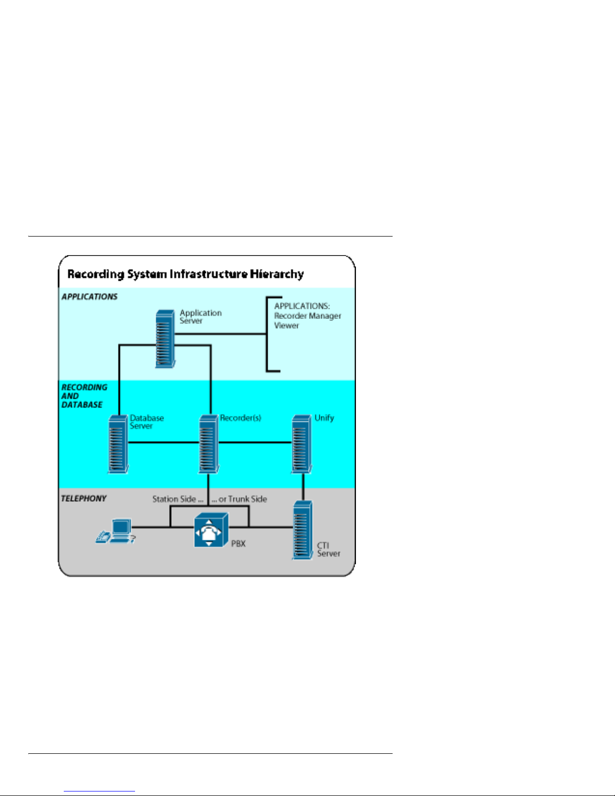
Nortel TDM Recorder at a glance
The Nortel TDM Recorder consists of software components in a standard
PC that interfaces with other CTI components. Its primary purpose is to
record calls, especially for 100 percent compliance situations. At the same
time, the superior performance of the Nortel TDM Recorder is apparent as a
standalone solution. Combined with the ease of use and management of a
portal-style interface, the Nortel TDM Recorder allows customers to have
centralized control of all their recording activities.
The Nortel TDM Recorder (Time Division Multiplexing recording, as
opposed to IP recording) system infrastructure consists of telephony,
recording subsystem, and hardware and software components, as shown in
the diagram.
Page 17
September 2007 Nortel TDM Recorder
System Infrastructure Guide 17
These are further described in “Nortel TDM Recorder features and benefits”
on page 19.
Page 18
Nortel TDM Recorder Standard 3.0
18 Nortel TDM Recorder
Nortel TDM Recorder management
The Nortel TDM Recorder is accessed and managed from any Internet
Explorer 5.5 or later web browser. The interface allows simplified access to
control, manage, and monitor all features in the recording system, including
specific programs and add-on components. Through a tabbed interface,
users select specific areas to access features. Access depends on security
level.
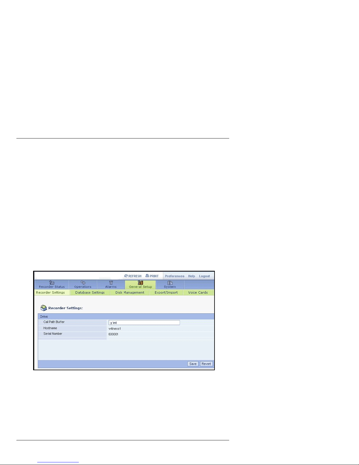
Administration and management of the recorder is accomplished through
the Recorder Manager. The Recorder Manager controls all components,
alarms, and other activities on the individual recorder.
The following is an example of the Recorder Manager interface:
The Recorder Manager is further described in “Nortel TDM Recorder
features and benefits” on page 19.
Page 19

September 2007 Nortel TDM Recorder
System Infrastructure Guide 19
Nortel TDM Recorder features and
benefits
The Nortel TDM Recorder runs on a Windows 2003 server with Service
Pack 1.
Recorder features include Distributability, Extensibility, Reliability,
Scalability, and Diagnostics, as described in the following:
Feature/Benefit Description
Distributability Recorder uses standard protocols that enable
deployment in a wide variety of enterprise
environments.
Extensibility Recorder can be deployed in dynamic environments and
supports only one manufacterer (Ai-Logix) of voice
cards, new technologies and integration with new
encoding formats.
Reliability If the network goes down, the Recorder can fall back on
tap-sense control.
Scalability Recording capabilities can be scaled to any organization
size by simply adding Recorder servers.
Diagnostics The Recording system is easy to support and the flow of
data between components is intuitive, resulting in easier
analysis and support for customers and engineers.
Page 20

Nortel TDM Recorder Standard 3.0
20 Nortel TDM Recorder
Nortel TDM Recorder management
features and benefits
The TDM Recorder management tools allow simplified system
administration functions for the recording system. Recorder Manager and
Enterprise Manager provide the following features and benefits.
Feature/Benefit Description
Improved account
management
Simplifies the management of user accounts to a single
point of administration, thereby reducing operational
costs and errors.
Highly usable Provides high visibility to all installed products
Simplified login Allows a single source of managing multiple recorders
through a single point of login. The features and the
ability to manage/control the different parts of the
recorder are based on the access rights granted to the
logged in user.
Improved alerting Provides centralized alerting and notification delivery
capability.
Ease of
deployment and
use
Decreases IT support costs and reduces system
configuration errors resulting in increased customer
satisfaction and increased competitiveness in the
marketplace
Page 21

System Infrastructure Guide 21
Chapter 3
Infrastructure at a Glance
In this chapter
Nortel TDM Recorder in the workplace 22
Implementation summary 27
Using Nortel TDM Recorder databases 35
Page 22
Infrastructure at a Glance Standard 3.0
22 Nortel TDM Recorder
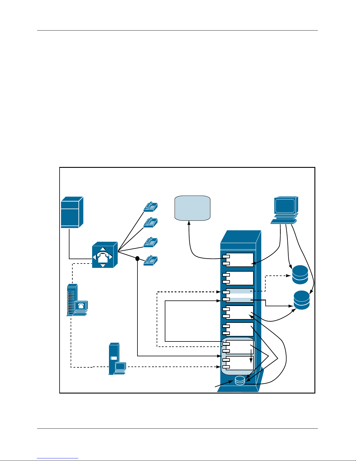
Nortel TDM Recorder in the workplace
Nortel TDM Recorder is engineered to offer a new generation of
performance through improved functionality, scalabilit,y and dependability
over existing recorder platforms. It forms the underlying platform for a
number of other systems that offer call control, replay, analysis, e-learning,
and quality monitoring functions.
The Nortel TDM Recorder infrastructure is shown in the following
illustration:
For more information, refer to “Recording Server environment” on page 61.
Consolidator
Workflow
Manager
Disk
Manager
Capture
Engine
Ai-Logix
Voice
Card
Call Buffer
Write
Delete
Media
Calls
Archiver
(local)
Retriever
.xml files
.wav files
PSTN
TDM Recorder Station-Side Recording
SAN, DVD
Archiver
(remote)
CAM
Viewer
Media
Database
Calls
Database
Unify
Server
CTI
Server
PBX
Page 23

September 2007 Infrastructure at a Glance
System Infrastructure Guide 23
This section is described in the following topics:
Staffing
Location of system
Tasks performed
System uses
Operation
Archiving
Staffing
Normally, only one or two IT staff members can access the recorder for
maintenance and configuration. Typically, only one person at a time works
on the system. This is also typical in an enterprise environment where a
recorder with the Enterprise Manager is located. Then only one or two
persons, including the system architect and authorized system
administrators, access the Enterprise Manager and other locations within the
enterprise. The many users who work with the recorder for activities such as
call replay and record control do so through other applications.
Location of system
The Nortel TDM Recorder operates optimally in a communication center or
information technology server room with air conditioning and secured
access. Physical contact with the recorder is limited to maintenance-type
functions or situations where archive media needs to be changed.
Tasks performed
The following table estimates roles and work performed by users of the
Nortel TDM Recorder:
Page 24

Infrastructure at a Glance Standard 3.0
24 Nortel TDM Recorder
System uses
The recorder is connected to application, database, and control systems that
use the output from the recorder. The main users of recordings do not
interface directly with the recorder but instead use the systems summarized
in the following table:
Role Duties
Customer's IT Support
Staff
Support and operation of the recorder with the
customer's environment.
Remote Support Engineer Support of the system from a remote help desk.
May be a Nortel support representative.
Customer Compliance or
Audit Personnel
Ensures that use of the recorder system
complies with company quality objectives
Maintenance/Installation
Administrators
Installation and maintenance of hardware and
software at one or more locations.
Customer Media
Administrators
Manages the archive media such as tapes and
DVDs to enable continued archival of critical
data and ensures users can access archived
materials.
System Description
Replay systems such as
Vision, Viewer, Archive,
Audio Server
Pull calls from the recorder for use by their
users.
Page 25

September 2007 Infrastructure at a Glance
System Infrastructure Guide 25
Operation
The main purpose of the recorder is recording and analysis. At its basic
level, the recorder system consists of applications that search a database of
call references and requests the transfer of a specific call from the recorder
for replay to the user. The recorder uploads the call references to a database
for the applications to search for, and respond to, replay requests. Calls are
controlled either by the signaling on the telephony lines or by way of a
business logic server (BDR server) that takes data, either CTI or other
business data, to determine if the call should be recorded and what attributes
should be linked to the call. The recorder responds to this control input by
setting up and initiating recording and attaching any business attributes to
the call record.
Management Tool
In addition to the normal operation of the recorder is the Recorder Manager.
This administration application is responsible for such actions as channel
allocation, alarm notification, and archive management.
Control Systems such as
Unify and Business
Driven Rules (BDR)
servers
Analyze business data and CTI information to
determine if a call should be recorded and to
tag that call with any relevant business
information that will add value.
Call and Event databases Upload call details to allow applications to
search and replay calls.
Audit database Upload configuration and call replay
transactions
Alarm Notification Monitor alarm counters and events.
Enterprise Configuration Download and upload configuration
information, copy and redeploy configurations.
System Description
Page 26

Infrastructure at a Glance Standard 3.0
26 Nortel TDM Recorder
Archiving
Calls are kept on the recorder in a circular calls buffer. Calls are either
archived to DVD or tapes located in the recorder, or the calls are “pulled” to
an external archiving server for storage. Archive activities are performed by
the Archive Manager software component.
Only certain Panasonic DVD drives and only HP DAT72 tapes are
supported for Archive.
DVD drives supported:
Only the Panasonic Range of DVD-RAM devices are currently supported.
These are the LF-D311, LFD521E or OEM equivalent SW-9571, or the LFM621U or OEM equivalent SW-9572-CPN devices. Nortel currently
recommends only 4.7 GB cartridges (as opposed to cartridgeless) disks.
Use the device driver on the installation CD that comes with the device or
download at the Panasonic driver website at the following url: http://
panasonic.co.jp/psec/support/dvdram/lim/eoem/index.html.
Each side of the DVD-RAM media can hold approximately 550 hours of
voice recording based on typical call lengths.
Tapes supported:
Only HP DAT72 tapes are supported. Use the device driver on the
installation CD that comes with the device or download at the HP driver
website (www.hp.com, clicking Support and Drivers and searching for
DAT72).
Each tape can hold 36 GB (without compression) or 72 GB (with
compression) of voice recording based on typical call lengths.
Page 27

September 2007 Infrastructure at a Glance
System Infrastructure Guide 27
Implementation summary
The Nortel TDM Recorder Server integrates synchronized voice and data
monitoring. It also interfaces with databases, archive mechanisms, CTI
servers, and other servers. The following topics should be considered in the
implementation of Nortel TDM Recorder server:
Physical connectivity options
Network operating system
Server hardware components
CTI Servers
Voice cards
Physical connectivity options
Data-application Servers may be installed on Ethernet (100/1000 Mb/s)
server backbones. The Server operating system must be configured with the
network's default router IP address, and must be able to reach all agent
workstations by way of ping.
Installers have flexibility on where to deploy the Nortel TDM Recorder
Server in the enterprise environment. However, they should bear in mind
that data capture response times will fluctuate in direct correlation to the
average packet delivery times provided by the network segments traveled.
WAN data capture is fully supported but may result in reduced quality of
playback for users.
In all circumstances, installers should try to physically co-locate the Nortel
TDM Recorder Server with replay users.
Page 28

Infrastructure at a Glance Standard 3.0
28 Nortel TDM Recorder
Network operating system
TDM Recorder installs on the Windows 2003 server with service pack1
using Windows Server Software. By default, the Server is installed as a
stand-alone Server in the NT domain model. It is recommend that you do
not configure the Nortel TDM Recorder Server as a Backup or Primary
Domain Controller, nor configure the server to participate in any NT
replication scheme.
DNS/WINS/HOSTS/LMHOSTS - Nortel TDM Recorder Application
Servers allow several different hostname-to-IP address resolution methods
for simple deployment in heterogeneous LAN environments.
The Nortel TDM Recorder server software does not directly interface with
TCP/IP, relying on the server's operating system to handle all IP resolution.
Server hardware components
Configurable hardware components of a typical Application Server include:
SCSI Hard Drive Array: Typically, all operating system and other
software is maintained on its own SCSI hard drive, mirrored RAID 1 on a
single controller. All voice and data files are typically stored on a RAID
5 (stripe set with parity) array.
Ai-Logix Voice Cards: In TDM deployments, voice connectivity is
handled by one or more digital voice cards. These cards are employed to
provide 24 or 30 digital voice channels connecting to a corresponding T1
or E1 circuit, respectively, within the ACD/PBX. Ai-Logix analog cards
can also be deployed.
Network Interface Card: Standard protocol configuration must be
entered into Windows’ Server Network applet in the Windows Control
Panel including default gateway, subnet mask, and DNS/WINS Server
addresses and names. NIC teaming (combining multiple NIC resources)
is supported.
Page 29

September 2007 Infrastructure at a Glance
System Infrastructure Guide 29
For more information on server hardware and software components, refer to
“Recording Server environment” on page 61 and “Configuring Primary
Recorder Components” on page 113.
CTI Servers
It is strongly recommended that you install CTI-server software on a
separate server from the Nortel TDM Recorder Application Server. Nortel
TDM Recorder uses a separate server so that other servers can access the
data without degrading the performance of the recorder.
Voice cards
Only Ai-Logix cards (T1 or E1) are used in the Nortel TDM Recorder
infrastructure. These can be either Digital or Analog card types. For most
ACD switches, these server-resident voice cards provide the full interface to
the contact center's telephony infrastructure. For voice card installation and
wiring information, refer to “Voice card installation and wiring” on page 69.
For compatible voice card types and configuration using the Recorder
Manager, refer to “Configuring voice cards” on page 97.
Page 30

Infrastructure at a Glance Standard 3.0
30 Nortel TDM Recorder
Hardware Summary
Item Description Details
Recorder Server Standard Server Platform
(such as HP, IBM, AdTech,
Alliance Systems)
3GHz Dual Processor Xeon
3GB RAM
RAID for Call Buffer
Expansion Chassis for more
slots
Large System = 360 Channel,
Single Box Solution (MS SQL
eWare Database, Viewer,
Recorder and Unify on a
single server)
MS SQL 2000, MSDE
Supported
Windows 2003 Server Windows 2003 Server must
have service pack1
Page 31

September 2007 Infrastructure at a Glance
System Infrastructure Guide 31
Voice Cards PCI 2.2, 3.3 Volt, Full Length
PCI Form Factor
Onboard DSPs – G726, G729a
compression
High Impedance Cards (so no
AHIB is required)
All major PBXs supported
Maximum cable lengths and
wiring diagrams are in AiLogix docs
E1/T1 Trunk-side Tap DP3209 (single T1/E1) and
DP6409 (dual T1/E1)
ISDN, Robbed Bit, NFAS
DET (Station-side) Tap NGX800 (8 channels)
NGX1600 (16 channels)
NGX2400 (24 channels)
Analog Tap LD409 (4 channels)
LD809 (8 channels)
LD1609 (16 channels)
LD2409 (24 channels)
PT409 (4 channels)
PT809 (8 channels)
PT1609 (16 channels)
(discontinued)
Item Description Details
Page 32

Infrastructure at a Glance Standard 3.0
32 Nortel TDM Recorder
Archive Devices HP DAT72
DDS5 Tape Drive - 36GB
capacity
Only HP DAT72 tapes are
supported. Use the device
driver on the installation CD
that comes with the device or
download at the HP driver
website (www.hp.com, click
Support and Drivers and
search for DAT72).
Each tape can hold 36 GB
(without compression) or
72GB (with compression) of
voice recording based on
typical call lengths.
DVD-RAM 4.7 GB Only the Panasonic Range of
DVD-RAM devices are
currently supported. Models
are the LF-D311, LFD521E or
OEM equivalent, SW-9571,
LF-M621U or OEM
equivalent SW-9572-CPN
devices.
Only 4.7 GB cartridges (as
opposed to cartridgeless) disks
are recommended.
Use the device driver on the
installation CD that comes
with the device or download
at the Panasonic web site
http://panasonic.co.jp
Each side of the DVD-RAM
media can hold approximately
550 hours of voice recording
based on typical call lengths.
Item Description Details
Page 33

September 2007 Infrastructure at a Glance
System Infrastructure Guide 33
Recorder Sizing Fewer than120 channels > Single 3GHz processor
360 channels > Dual 3 GHz processors
Over 360 channels (that is,
more than one recorder) >
Break out Unify/eWare to
separate servers
Disk performance Use 64k cluster size on the call
buffer to avoid impact of
fragmentation
Database should be on
separate physical disks/bus
from call buffer for maximum
performance
Suggested Disk Layout:
C Drive: Windows Operating
System (10 GB min)
D Drive: Program Files
Installation Directory, Trace
Logs, Postgres Workflow DB,
Archive Temp Directory (40
GB Min)
E Drive: MS SQL Database
(20 GB Min)
F Drive: Call Buffer (64k
cluster size) (10 GB min)
Item Description Details
Page 34

Infrastructure at a Glance Standard 3.0
34 Nortel TDM Recorder
Recorder PC
Considerations
Does the recorder system have
enough PCI slots?
Most mainstream servers max
out at 3 PCI slots
Expansion chassis is often
needed
A TDM bus cable is not
required, so that cards can be
split between the host system
and an external chassis
Performance can degrade if
there are more than 4 PCI
bridges between the host CPU
and the cards
PCI Express expansion
chassis can be used.
Recorder Cooling
and Power
consideration
Does system have enough
cooling and power capacity for
voice cards?
AdTech and Alliance Systems
validate systems for power,
airflow and temperature
Ai-Logix provides
specifications for power
requirements
Item Description Details
Page 35

September 2007 Infrastructure at a Glance
System Infrastructure Guide 35
Using Nortel TDM Recorder databases
This section presents information regarding the databases that the Nortel
TDM Recorder connects to, as well as the XML schema it uses. XML is
used by Nortel TDM Recorder to present configuration information and
contact metadata. The configuration XML is not connected to the database
in any way; it is simply read by the Nortel TDM Recorder from the local
disk.
The Nortel TDM Recorder uses two databases: the Calls database and the
Media database. These are shown in the following simplified diagram:
Illustration of call elements being stored separately
Note: This section uses SQL Server terminology. If SQL Server is not
installed, a default MSDE database is installed.
Calls
Database
Media
Database
Voice
Card (Ai-Logix)
Call received
from Unify (via
PBX and CTI Server)
Associated data (meta-data)
captured in XML file
Voice portion of
call captured in WAV file
Page 36

Infrastructure at a Glance Standard 3.0
36 Nortel TDM Recorder
Calls database
The Calls database stores the metadata for recorded Contacts. This metadata
includes channel, duration, start time, and user-defined fields. The
Recorder's input to this database is achieved through a stored procedure
named AddXML. The stored procedure is responsible for parsing an XML
file that describes the Contact metadata and persisting that data properly into
the database. The primary table, which stores Contact metadata, is called
tblCalls. The Viewer application uses a series of views created on this
database to allow each customer to tailor the display of Contact metadata to
their environment.
Media database
The Media database keeps track of the files that store the Contact data and
metadata. It also facilitates the Enterprise Archive capability of
ContactStore Archive by maintaining information about which disks,
DVDs, and tapes are storing individual files specific to Contacts. The role
that the Recorder itself plays in this process is limited: it updates the Media
database after the call is initially recorded to indicate that there is a copy of
the Contact on the Recorder's call buffer. Once the Contact has rolled-off
the call buffer, the Recorder again must update the Media database to
indicate that the Contact is no longer available on the Recorder's call buffer.
How many databases are needed?
The answer to how many databases are needed depends on resources. SQL
Server allows you to create multiple logical entities that it calls databases.
Each database can be configured to have its own characteristics, such as
security and file system. Typically, large companies have numerous
physical databases, such as separate Payroll and Purchasing databases for
example.
Page 37

September 2007 Infrastructure at a Glance
System Infrastructure Guide 37
You can have two separate physical databases: Calls and Media. The Calls
database is where the main viewer query is done. The Media database is
where the Retriever component looks for the tape on which the call is
located.
Database stored procedures
One set of stored procedures is used to handle Contacts stored on a
Recorder's call buffer. A different set of stored procedures is used to handle
Contacts stored on an archive medium.
Call buffer stored procedures
The stored procedures used for the call buffer are:
Archive media stored procedures
The stored procedures used for archive media are:
Procedure Description
NGADiskBuffer_Add Called when a new Contact is created by the
Recorder.
NGADiskBuffer_Update Called when the Contact's size or format has
changed.
NGADiskBuffer_Removed Called when the Contact has rolled off the
buffer.
Procedure Description
Archive_DriveDetected Called when a new DVD, tape, or other drive is
detected.
Archive_AddMedia Called when a blank tape or DVD is initialized.
Page 38

Infrastructure at a Glance Standard 3.0
38 Nortel TDM Recorder
XML specification
XML is used in Nortel TDM Recorder to describe configuration of the
Recorder and persist metadata for each Contact.
Archive_MediaIs Called when a previously used DVD or tape is
reinserted.
Archive_AddComposite Called when a new tarball has been written to a
DVD. If tarballs are used with tape archive in
Nortel TDM Recorder then this would be called
when a tarball was written to the tape as well.
Item Description
eRecorder Meta Data
XML Schema.doc
Describes the XML schema used for metadata
persistence.
ERecorder_Configuration
_XML _Schema.doc
Describes the XML schema used for
configuration.
Procedure Description
Page 39

System Infrastructure Guide 39
Chapter 4
Call Recording and Playback
In this chapter
Common recording methods 40
Recording 43
Recording and playback 50
Page 40

Call Recording and Playback Standard 3.0
40 Nortel TDM Recorder
Common recording methods
Passive tap trunk side recording
This method taps directly into a T1 or E1 line to record all incoming calls at
the demarcation point before going to a switch. In general, passive tap
recording caches a recording of the entire contact on the recording system. If
an event does not trigger storage of the recording within a specified period
of time, the cached recording is deleted from the system.
Passive tap trunk-side recording requires a physical connection directly
between the demarcation point and the switch system. The physical
connection is implemented by placing a junction box on the inbound T1 or
E1 line. One junction box is required per trunk to be monitored. Further, two
T1 or E1 voice board spans are required per junction box to capture voice
data from both the customer voice channel and the agent voice channel. The
following diagram illustrates a passive tap trunk-side configuration
deployed within a Call Center environment:
Page 41

September 2007 Call Recording and Playback
System Infrastructure Guide 41
Trunk-side recording requires two spans for every one span being tapped.
The first span is for recording the agent (transmitter); the second is for the
customer (receiver) side.
Passive tap station side recording
Passive tap station-side recording initiates recordings between the switch/
ACD and a phone by tapping into the line that connects the switch to the
telephone by way of a punch-down block. A cable is installed so that each
extension connects directly to a port on the voice card. The passive tap
Station-side configuration deployed within the Call Center environment is
illustrated in the following illustration:
PSTN
T1 Line
Note: 1 junction box
required for each T1 line.
PBX
CTI
Server
Punchdown
Block
Junction
Box
Passive Tap: Trunk Side Recording
Recorder Server
Sysadmin/
Supervisor
Server
Agent
Workstations
Unify Server
Voice Card for Passive
Tap recording
Page 42

Call Recording and Playback Standard 3.0
42 Nortel TDM Recorder
Span pair
A span is a term that refers to the wiring from the Voice Card on the
Recorder Server that taps into the telephone system. A span can be
extensions connected to the Switch or a T-1 connected to the public Tcarrier. For Passive Tap recording, each span connects the voice card to the
phone system's T1 or E1. Both spans may be associated with the same
related switch, or each span may be associated with different related
switches. The span pair is used for recording inbound calls only; outbound
calls are ignored, hence the term “passive”.
PSTN
Passive Tap: Station-side Recording
Recorder Server
Sysadmin/Supervisor
Server
Agent
Workstations
PBX
DB
Archival
Storage
PLAYBACK
RECORDING
CTI
Server
Punchdown
Block
Unify Server
T1 Line
Voice Card for Passive
Tap recording
Page 43

September 2007 Call Recording and Playback
System Infrastructure Guide 43
Recording
Before a recording can begin, the capture engine of the Recorder verifies
that a valid license exists, then detects voice cards. Once these prerequisites
are done, the Capture engine proceeds to capture and record voice data and
metadata from either a CTI source (the primary source) or from a voice card,
while at the same time allowing for backup recording when the CTI source
is unavailable. Finally, the capture engine persists and consolidates data to
local archive devices, including data from another Recorder if one exists.
These tasks are described in the following sections:
Recording prerequisites
Auto-detecting telephony cards
Validating licensing
Capturing and recording voice data
Capturing and recording associated call data
Capturing CTI-initiated contact
Capturing voice card-initiated contact
Control Fallback
Recording prerequisites
Recording prerequisites include detecting telephony cards and validating
licensing. After the Recorder has these prerequisites in place, capturing can
begin.
Auto-detecting telephony cards
The Recorder's capture component probes the system while initializing to
detect the existence of any telephony interface cards. The Capture
component then compares the detected card(s) with those that already exist
in the configuration file
config.xml. If any mismatch is reported, such as
new cards added or existing cards removed, moved, or replaced, a new file,
Page 44

Call Recording and Playback Standard 3.0
44 Nortel TDM Recorder
update.xml is generated. This file contains details of detected
mismatches, such as type of card, serial number, number of channels, and
PCI slot occupied. The Capture engine then recalculates logical to physical
channel mappings and writes to a log file, sounding an alarm if a card fails
to initialize. The card finally has to be acknowledged (by clicking Accept)
and configured.
Validating licensing
The Recorder's Capture component loads and decodes the license key
during startup and then enforces channel licensing when requests to record
calls are received. During startup, the license key is read from the system's
configuration file,
config.xml. The license key is then decoded and its
authenticity verified. Upon verification, channel configurations are loaded
from the
config.xml file and validation of the number of channels
configured compared to the actual number of channels licensed. Next, a
request (CTI driven) or event (Tap Sense) is issued to the Capture engine to
start recording a call. After checking that the requested channel to be
recorded is licensed, the Capture engine starts recording the channel,
generating an audit log at the same time.
If one or more of the following License Key conditions exists, the capture
engine is not initialized:
Missing
Tamp ere d
Invalid or Expired
Configuration Mismatch
Channel not Licensed
Page 45

September 2007 Call Recording and Playback
System Infrastructure Guide 45
Capturing and recording voice data
Capturing and Recording voice data describes capturing the voice data
portion of a call and converting it into a
.wav file for later retrieval and
playback. The non-voice data portion of a call, known as associated data or
metadata, is captured separately, as described in “Capturing and recording
associated call data” on page 47.
The recording is initiated by a request from the call controller, either the
Controlling Engine (Unify) based on CTI events, or, if detected, a Tap Sense
event on the telephony interface card. In effect, Unify makes all decisions on
recording actions, while the telephony interface card provides voice data and
telephony events to the Capture Engine. Where Unify is unavailable for
some reason, recording is initiated directly from the telephony interface card
using Tap Sense. This is described in “Control Fallback” on page 49.
The following telephony interface cards are supported
Type Ai-Logix
Model
Description
Analog
Station
Side
PT409, PT809,
PT1609
Voice cards capable of recording 4, 8 and 16 ports
respectively. These cards are currently supported by
ContactStore Express and are supported for
backwards-compatibility with those customers.
These cards do not generate a loss of signal (LOS)
alarm.
Analog
Station
Side
LD409, LD809,
LD1609,
LD2409
Newer versions of Ai-Logix's analog station-side
recording voice cards capable of recording 4, 8, 16
and 24 ports respectively.
Page 46

Call Recording and Playback Standard 3.0
46 Nortel TDM Recorder
Voice data formats supported include ALAW, ULAW, G726, and G729A.
The Capture Engine processes the call start and initiates the record on the
telephony interface card channel. Once notified that recording has started,
the Capture Engine processes the incoming data stream of voice data from
the call, and saves it to the disk in
.wav file format. When the call is
finished, the process is reversed: the Call Controller (i.e. Unify or the
telephony interface card) issues a stop call to the Capture Engine, which
terminates the recording operation on the telephony interface card channel
and confirms to the Call Controller that recording has stopped. The end
result is a named
.wav file on the hard disk. The file name is correlated with
the call’s metadata using the inum of the call, as described in the next
section.
Digital
Station
Side
NGX800 Voice card that records 8x2-wire digital stations
(4x4-wire). It is triggered by D-channel events. Can
have up to two MX80 daughterboards attached.
NGX1600 Voice card that records 16x2-wire digital stations
(8x4-wire). It is triggered by D-channel events. Can
have up to one MX80 daugtherboards attached
NGX2400 Voice card that records 24x2-wire digital stations
(12x4-wire) triggered by D-channel events.
MX80 Daughterboard that can be installed on NGX800
and NGX1600 voice cards.
Digital
Trunk Side
DP3209
DP6409
Passive-tap recording voice cards capable of
recording 30 (DP3209) and 60 (DP6409) channels.
They are software switchable between E1 and T1.
See also: http://www.ai-logix.com.
Type Ai-Logix
Model
Description
Page 47

September 2007 Call Recording and Playback
System Infrastructure Guide 47
Capturing and recording associated call data
Recording associated call data involves capturing the metadata portion of a
call, such as call start time and call end time, and converting this information
into a
.xml file for later retrieval and playback. The voice data portion of a
call, known as voice data, is captured separately, as described in Capturing
and Recording Voice Data in the previous section.
Metadata recording is initiated by a request from the Call Controller, either
the Controlling Engine (Unify) based on CTI events, or, if detected, a Tap
Sense event on the telephony interface card. Where Unify is unavailable for
some reason, recording is initiated directly from the telephony interface card
using Tap Sense. This is described in “Control Fallback” on page 49.
Metadata formats recorded in the
inum.xml file depend on whether Unify
or a telephony interface card is used as the recording mode. If Unify is the
recording mode, the following metadata is recorded: Dialed Digits, CLI
digits, DNIS, Call ID, Call Direction, and User-defined fields. If the
telephony interface card is the recording mode, the following metadata is
recorded:- All cards: Channel Name, Channel Number, Static tags (such as
start time, stop time, length, and so on); Trunkside Cards: DNIS; DET
cards - Extension, CLI, Lamp; Analog Cards: Digits.
The process begins when the Controlling Engine (Unify) asserts a start call
to the Capture Engine, which generates static metadata tags such as start
time. When the call is finished, Unify asserts a stop call, generating
metadata tags such as stop time. At any time while the call is in progress, or
after the call, the Call Controller tags additional call metadata used by the
Capture Engine in persisting the metadata to the .
xml file while asserting the
file to the Consolidator for uploading to the database. This cycle is repeated
for all calls.
Page 48

Call Recording and Playback Standard 3.0
48 Nortel TDM Recorder
The end result of each call is a file named inum.xml on the database where
inum is the serial number of the capture card plus the inum value of the call.
For example, the 7th call recorded by a capture card with serial number
600001 could be
600001000000007.xml. The file name is correlated with
the call's voice data in the
.wav file with the same inum. In the example, the
voice data file would be
600001000000007.wav. A third file, a database
file, with the same name is also created.
In playback, the replay application, such as Viewer or Vision, searches the
database on a particular criteria, such as
inum, to find the call. For archiving
purposes, the metadata
.xml file along with the corresponding.wav file can
be configured to be persisted to a permanent archive storage device such as
tape or DVD.
Capturing CTI-initiated contact
The normal method for capturing contacts is using Unify. In Unify control
mode, Unify monitors the CTI events for configured extensions from the
switch. Based on incoming CTI events, Unify decides to start or stop
contacts according to customer needs. The recording process is controlled
by the Unify script as described in “Recording and playback” on page 50.
Unify then captures voice data and metadata, as described in “Capturing and
recording voice data” on page 45 and “Capturing and recording associated
call data” on page 47. Metadata captured includes
Dialed Digits, CLI
digits
, DNIS, Call ID, and Call Direction. Unify may also tag
any desired user-defined fields for inclusion in the
inum.xml file.
When CTI-initiated contact recording is not possible, fall back mode using
Tap Sense and the telephony interface card is used, as described in “Control
Fallback” on page 49.
Page 49

September 2007 Call Recording and Playback
System Infrastructure Guide 49
Capturing voice card-initiated contact
Capturing contacts using only the telephony interface card (the voice card)
is based on digital or analog events from the tapped line. In Tap Sense
recording mode, events are asserted from the tapped telephone line. For
example, a Punchdown Block can be used to tap a telephone line by forming
an additional connection to that line.
Tap Sense recording mode can be started in one of three ways:
1. The Capture Engine can be configured to always perform Tap Sense
Recording
2. Unify can instruct the Capture engine to switch to Tap Sense recording in
the absence of the CTI source
3. The Capture Engine loses the connection to Unify and automatically
switches to Tap Sense recording. Methods 2 and 3 are described in
Control Fallback
Control Fallback
Control Fallback is the backup system for Capturing CTI-initiated Contacts.
Whenever Unify is not available to record the starting and stopping of calls,
an alternate method is used: the telephony interface cards. Here, calls are
recorded using Tap Sense recording mode, thus providing a fail-safe method
for continuous call recording.
The switching between recording modes begins when Unify detects that the
CTI source is disconnected and invokes the fallback mode on the Capture
Engine. Then, procedures described in Capturing Tap Sense-initiated
Contacts are followed. When Unify detects that the CTI source is
reconnected, the fallback mode is switched off and the CTI source resumes.
Page 50

Call Recording and Playback Standard 3.0
50 Nortel TDM Recorder
Recording and playback
Recording and providing Contacts for playback using Internet Protocol (IP)
are the primary functions of the Nortel TDM Recorder. The interface used
by Viewer for playback is designed to be a uniform HTTP interface that can
be used to retrieve Contact data and metadata for a variety of purposes,
including Enterprise Archive. This section shows how the sub-components
of the Recorder cooperate for recording and playing back a Contact in a
greyfield environment (that is, where there are unify scripts for a mediastore
and the Nortel TDM Recorder). The Contact may be located either on the
Recorder's local call buffer or on a tape or DVD on the Recorder server. This
information is described in the following topics:
Capturing a Contact (recording)
Alternative methods of capturing a contact
Replaying a Contact located on the Recorder's local Call Buffer
(Playback)
Replaying a Contact located on a Recorder’s tape or DVD (Playback)
Capturing a Contact (recording)
Capturing a Contact is initiated when the Unify Script receives an event that
indicates that a monitored extension or trunk channel has begun a call. The
script issues a start recording (
startRecord()) message to the Recorder
which replies asynchronously when it has started recording.
When the Unify Script receives a later event indicating that the call has
ended, it issues a stop recording (
stopRecord()) message to the recorder,
which again responds asynchronously. Inside the recorder after recording
has stopped a series of events occur that cause the metadata to be uploaded
to the Calls database and the voice data and its metadata to be archived to
the Media database and to an external storage device. This is described in
the following steps and illustrated in the following diagram:
Page 51

September 2007 Call Recording and Playback
System Infrastructure Guide 51
Capture a Contact showing scripting commands.
Issuing the Start command
Recording begins when Unify receives an event (that is, a call has started)
from the CTI server:
1. The Unify Script issues a
startRecord() message to the Recorder.
The message contains an identifier for the channel that should start
recording. The Workflow component of the Recorder acts as a
communication broker between the Recorder and Unify.
2. The Capture Engine asynchronously begins to read data from a buffer
presented by the Voice Card API. This process is actually a periodic
callback by the API that contains the next packet of voice data. As the
Archiver
Workflow
Manager
Capture
Engine
Unify
Disk
Manager
Capture a Contact
Consolidator
Consolidator
2.3 recordingStopped( inum)
1.1 start Record( channel)
1.2 recordingStarted( channel, inum)
2.1 stopRecord( channel)
2.2 recordingStopped( channel)
2.4 consolidated( inum)
2.6 consolidateComplete( inum)
2.8 archiveCompleted( inum)
3.2 contactDeleted( inum)
3.1 contactDeleted( inum)
2.5 archive( inum)
2.7 archiveComplete( inum)
Page 52

Call Recording and Playback Standard 3.0
52 Nortel TDM Recorder
callbacks are received, the Capture Engine streams the buffers to disk in
the form of a WAV file.
3. Once the callback has been activated, the recorder responds
asynchronously to the Workflow that recording has started on the
channel and provides a unique identifier for the Contact, the
inum.
Issuing the Stop command
1. When the call has finished, the Unify Script issues a
stopRecord()
message to the Recorder.
2. The Capture Engine asynchronously de-registers the callback for the
channel and closes out the WAV file once all of the packets are received.
3. The Capture Engine responds asynchronously with a message indicating
that recording has stopped.
4. The Capture Engine sends the
recordStopped() message on to the
Workflow to manage the post-recording life of the Contact.
5. The Workflow initiates the post-processing of the Contact by sending a
consolidate() message to the Consolidator to cause the Contact
metadata to be uploaded to the Calls database. The message contains the
inum of the Contact.
6. The Workflow then sends an
archive() message to the Archiver
component so that archiving and consolidation can be done in parallel.
7. The consolidator locates the XML file containing the Contact metadata
on disk by the
inum. The consolidator then updates the database with the
Contact metadata contained in the XML file. Once completed it sends an
asynchronous
consolidateCompleted() message to the Workflow.
8. The Archiver locates the Contact WAV and XML metadata by
inum on
the disk. The Archiver writes the WAV and XML to the tape or other
external storage. The Archiver responds asynchronously to the Workflow
once archive is complete for the Contact.
Page 53

September 2007 Call Recording and Playback
System Infrastructure Guide 53
Ensuring enough disk space
1. The Disk Manager periodically examines the call buffer for remaining
free space. When the free space has gone below a configured threshold,
the Disk Manager begins deleting the oldest Contacts until the threshold
has been reached.
2. Once the Contact has been deleted the Disk Manager informs the
Workflow. The Workflow relays the message to the Consolidator.
3. The Consolidator updates the Media database to indicate that the Contact
is no longer available on the Recorder's call buffer.
Alternative methods of capturing a contact
Two non-Unify methods for capturing a contact exist. The first is D-channel
capture and the second VOX Fallback or Secondary Mode:
1. Instead of the Unify Script issuing a
startRecord() command, the
Recorder itself issues a tap-driven StartRecord when it detects from a DChannel, Line Sense, VOX or some other tap-based means that a call has
started on the channel.
2. Instead of the Unify script issuing a
stopRecord(), the Recorder itself
issues a tap-driven
stopRecord(), similar to the Alternative for step 1.
Note that in an environment where VOX Fallback /Secondary Mode is
enabled, a tap-driven
startRecord() may be followed by a Unify-
based
stopRecord(), or a Unify-based startRecord() may be
followed by a tap-driven
stopRecord().
Page 54

Call Recording and Playback Standard 3.0
54 Nortel TDM Recorder
Replaying a Contact located on the Recorder's local Call Buffer
(Playback)
Replaying a Contact from the local Call Buffer begins when Viewer requests
the Contact data or metadata from the Retrieval interface on the Recorder.
Viewer first queries the Calls Database to provide a list of Contacts to the
user, who is normally the Supervisor but can be anyone else who has access
to Contacts through the Viewer. The Supervisor then chooses a Contact for
playback, as described in the following steps and shown in the following
diagram:
Steps in replaying a contact (Playback) from a local call buffer
Playing back a Contact from a local Disk Buffer is accomplished by
following these steps:
Viewer
Retriever
Locator
Replay a Contact located on the Call Buffe
r
1.1 query Contacts
2.1 get Contact
2.2 redirect to Viewer
2.3.1 Read from Disk
2.5 get Contact (HTTP)
2.7 redirect to Recorder
2.3 get Contact (HTTP)
2.4 return Contact
Viewer Web
Browser
Recorder
Server
Viewer
Server
Supervisor
Workstation
Call Buffer
(Internal
Disk Drive)
1.1.1 query database
Page 55

September 2007 Call Recording and Playback
System Infrastructure Guide 55
Executing a query
1. The Supervisor executes a query in the Viewer browser window to
display list of Contacts.
2. The HTTP request is executed in the Viewer Server Component.
The Viewer server component executes a Query in the Calls Database.
Selecting a Contact
1. The Supervisor selects a Contact to playback.
2. The Viewer browser executes an HTTP Get of the Contact data on the
Viewer Server component.
The Viewer Server component uses the Locator component to determine
the closest Recorder node to the Viewer browser that can service the
request. This allows the Viewer server to be located in a main office and
the browser and Recorder both in the same branch office. The Viewer
browser will be redirected to the nearby Recorder to service the request
rather than the Contact data being sent to the main office then back to the
local office.
The Locator component redirects the HTTP request to the Recorder
node.
This redirection is passed on to the Viewer browser.
3. The Viewer browser re-requests the Contact from the Recorder.
The Retriever component on the Recorder reads the Contact data from
disk.
4. The Contact data is returned to the Viewer browser.
Page 56

Call Recording and Playback Standard 3.0
56 Nortel TDM Recorder
Replaying a Contact located on a Recorder’s tape or DVD
(Playback)
In Replaying a Contact located on a tape or DVD, the Contact data has been
archived to tape or DVD after it has been moved off the disk buffer. The
Recorder follows the same steps as described for retrieving the Contact data
from the local Call Buffer. This time, however, the Retriever is unable to
locate the Contact data on the Call Buffer, so it checks the Media database to
see if the Contact is located on the archival storage medium that is currently
in the Recorder. The Media database is consulted only after the lookup on
local disk fails. This is because the Media database may be located off-site
and the lookup may be much slower than the disk buffer. Lookup on
Archival storage might be even slower than lookup on the Media database.
For this reason the Retriever looks here when the local disk lookup fails.
This is described in the following steps and shown in the following diagram:
Steps in replaying a Contact (Playback) from Archival Storage
Viewer
Retriever
Locator
Replay a Contact located on
tape/DVD on Recorder
2.3.1 Try to find
Contact on Disk
Recorder
Server
Viewer
Server
Supervisor
Workstation
Call Buffer
(Internal
Disk Drive)
1.1.1 query database
Tape/ DVD
Viewer Web
Browser
2.3 get Contact (HTTP)
2.4 return Contact
2.3.3 Read from
Archival Storage
2.3.2 query Media DB
for location of Contact
1.1 query Contacts
2.1 get Contact
2.2 redirect to Viewer
Page 57

September 2007 Call Recording and Playback
System Infrastructure Guide 57
Playing back a Contact from a tape or DVD is accomplished by following
these steps:
Executing a query
1. The Supervisor executes a query in the Viewer browser window to
display a list of Contacts.
The HTTP request is executed in the Viewer Server Component.
The Viewer server component executes a Query in the Calls Database.
Selecting a Contact
1. The Supervisor selects a Contact to playback.
The Viewer browser executes an HTTP
Get of the Contact data on the
Viewer Server component.
The Viewer Server component uses the Locator component to determine
the closest Recorder node to the Viewer browser that can service the
request. This allows the Viewer server to be located in a main office and
the browser and Recorder both in the same branch office. The Viewer
browser will be redirected to the nearby Recorder to service the request
rather than the Contact data being sent to the main office then back to the
local office.
The Locator component redirects the HTTP request to the Recorder
node.
2. This redirection is passed on to the Viewer browser.
3. The Viewer browser requests Contact data from the Retriever.
The Retriever attempts to locate the Contact on the local disk buffer and
fails.
The Retriever checks the Media Database and finds that the Contact is
located on the archival storage present in the Recorder.
Page 58

Call Recording and Playback Standard 3.0
58 Nortel TDM Recorder
The Retriever reads the Contact data from the archival storage and stores
it in a temporary cache.
4. The Contact data is returned to the Viewer browser.
Page 59

System Infrastructure Guide 59
Chapter 5
System Setup and Administration
In this chapter
Overview 60
Recording Server environment 61
Voice card installation and wiring 69
System administration components 84
First time login instructions 85
Chapter 5: Navigating the User interface 86
Page 60

System Setup and Administration Standard 3.0
60 Nortel TDM Recorder
Overview
After the Nortel TDM Recorder server and system has been successfully
installed, you are ready to configure the environment. This is accomplished
according to the various recording methods and the various recording
options, as described in Chapter 4, “Call Recording and Playback”
System setup and administration is included in the following topics:
Recording Server environment
Voice card installation and wiring
System administration components
First time login instructions
Navigating the User interface
Page 61

September 2007 System Setup and Administration
System Infrastructure Guide 61
Recording Server environment
Configuration of your Nortel TDM Recorder Server environment requires
that you first, in consultation with your System Architect, compare your
current work environment before and after the Recording Server
implementation. The following simplified illustration is an example of a
typical quality monitoring server environment for a single site.
The Nortel TDM Recorder infrastructure components are divided into
hardware and recorder software components. The basic protocol of
interfacing hardware and software is HTTP. Other protocols are also used.
Consolidator
Workflow
Manager
Disk
Manager
Capture
Engine
Ai-Logix
Voice
Card
Call Buffer
Write
Delete
Media
Calls
Archiver
(local)
Retriever
.xml files
.wav files
PSTN
TDM Recorder Station-Side Recording
SAN, DVD
Archiver
(remote)
CAM
Viewer
Media
Database
Calls
Database
Unify
Server
CTI
Server
PBX
Voice recordings in (to capture card)
Voice Recordings out (after conversion to
audio files)
Tagged Metadata in (to capture card)
Metadata out
(after conversion
to .xml files)
Each recorded
contact has
corresponding
metadata
Raw Metadata
Page 62

System Setup and Administration Standard 3.0
62 Nortel TDM Recorder
Hardware components consist of the following:
PSTN (Central Office Switch)
PBX (Organization's Switch)
Agent Telephones
CTI Server
Unify Server
Recorder (see below for details)
The Recorder consists of the following software components:
Capture Engine
Workflow Component
Consolidator
Calls Database
Media Database
Viewer
Retriever
Archive
Central office
The central office represents the public switched telephone network (PSTN)
where telephone calls originate. The PSTN switch communicates with the
PBX in such a way that calls are routed according to the setup of the PBX.
The PSTN is connected to the PBX by a T1 or E1 line.
Page 63

September 2007 System Setup and Administration
System Infrastructure Guide 63
PBX
The PBX is the secondary switch in a telephony network. This switch
communicates with the PSTN on one side and the organization's telephony
equipment on the other. Unlike the PSTN, the PBX provides audit trails of
all incoming calls, such as time the call started and stopped. This is known
as event data or metadata, which may or may not be used. If used, a CTI
server is normally involved as part of a chain of hardware that allows the
event data to be passed to, and interpreted by, recording hardware.
Trunk-side recording takes places between the central office and the PBX.
Station-side recording takes place after the call is switched from the PBX to
a local extension.
CTI server
The CTI server acts as a broker interface to the PBX. The CTI server
communicates with the many different models of PBX so that the
complicated and ever-changing task of programming a device to interface
with the PBX switch is eliminated. The CTI server thus extracts event data
(that is, call metadata) and renders it acceptable to the existing telephony
hardware of organizations. In the case of Nortel TDM Recorder, Unify
obtains event data from the CTI server and passes it, after mapping fields, to
the Recorder for conversion to a XML file.
Agent extensions
Agents use telephones to participate in the customer calls that are being
recorded. Each extension has a unique identifier, usually 4-digits. These
calls originate from the PBX and are recorded directly by the capture engine
independently of the collection of the call's metadata.
Page 64

System Setup and Administration Standard 3.0
64 Nortel TDM Recorder
Unify
Unify connects to the Computer Telephony Interface (CTI) Server. It uses a
standard script that is customized for a specific telephony environment and
does one or all of the following.
Acquires data directly from the switch
Acquires data from telephony middleware (that is, the Recorder)
Persists telephony information into the database
Allows interaction with other system components.
For call recording purposes, Unify polls data directly from the switch. Event
data is received by Unify in the form of tags. Unify uses the script to map
the event data to user-friendly names. For example a tag might contain the
DNIS of the call. Unify allows the renaming of tags so that instead of UDF
1, the tag would be named DNIS. Information is then passed to the capture
component of the Recorder for conversion to a machine-readable file such
as
60000010000007.xml.
Recorder
The Recorder consists of components that capture call data and propagate
this data to databases to allow retrieval and viewing. Software components
include the Capture Engine, Workflow, Consolidator, Database (Calls and
Media), Viewer, Retriever, and Archive software components. The functions
of these components are summarized in the following sections.
Capture Engine
The capture engine works with the capture card and records the call directly
from the PBX (station-side) and receives the metadata indirectly. The
capture engine records the call's audio portion directly from the tapped line
to the card's call buffer. It is the audio portion of the call that is heard by the
agent at their telephone extension. The metadata is extracted from the PBX
Page 65

September 2007 System Setup and Administration
System Infrastructure Guide 65
by the CTI Server, which sends the data to the Unify server, which maps the
data to user-defined fields before sending it to the capture engine for
conversion into an XML file. Although it took an indirect route, the
metadata ends up on the call buffer along with its audio counterpart.
The capture engine finally converts data on the call buffer into 2 files, each
with the same name but with a different file extension. The filename prefix
consists of the serial number of the capture card combined with the unique
inum value of the call. The file extension can be either xml or wav. This is
shown in the following example:
Consolidator
Workflow
Manager
Disk
Manager
Capture
Engine
Ai-Logix
Voice
Card
Call Buffer
Write
Delete
Media
Calls
Archiver
(local)
Retriever
.xml files
.wav files
PSTN
TDM Recorder Station-Side Recording
SAN, DVD
Archiver
(remote)
CAM
Viewer
Media
Database
Calls
Database
Unify
Server
CTI
Server
PBX
Call #7
Voice
Call #7
Raw Metadata
Where?
What?
6000010000007.xml
6000010000007.wav
Mapped Metadata for call #7
Voice (audio) data for call #7
Capture Component
SN: 6000001
Page 66

System Setup and Administration Standard 3.0
66 Nortel TDM Recorder
As an example, a call is received through the central office and directed
through the PBX switch to extension 2347, which is being tapped stationside for recording. Say, for example, the call is the 7th of the day. The serial
number of the capture card is 600001. The audio portion is captured and
converted to a WAV file named
60000010000007.wav. The metadata
portion of the call is captured and converted at the same time as a file named
60000010000007.xml.
The workflow component polls the capture engine periodically and upon
finding two files of the same name, passes the files to the consolidator for
furtherance to the databases.
Workflow manager
The workflow manager software component, among its many tasks, polls
the disk buffer of the capture engine periodically for matching files. Upon
discovering that a matching pair of files (except for file extension) exists on
the call buffer of the Capture Engine, the Workflow component copies the
files to the Consolidator. At this point, two sets of identical files (that is
60000010000007.wav and 60000010000007.xml in the example)
exist. Until the call files are copied by the consolidator to the database,
however, only the file set in the call buffer can be retrieved.
Consolidator
The consolidator component effectively transfers files from the Workflow
Manager component to the database. Just as the database is divided into the
calls database and the media database, the consolidator consolidates
according to the file type. The media consolidator copies the media file
(
60000010000007.wav in the example) to the media database. The calls
consolidator copies the metadata file (
60000010000007.xml) to the calls
database.
Page 67

September 2007 System Setup and Administration
System Infrastructure Guide 67
Database (calls and media)
The database is where call information is stored. Call information consists
of an audio portion and a metadata portion, which are copied from the
consolidator. The consolidator consolidates the audio portion of the call as a
WAV file into the media database. At the same time, the consolidator
consolidates the metadata portion of the call as an XML file into the calls
database. For more information on databases, refer to “Using Nortel TDM
Recorder databases” on page 35.
Updating of the database is done by the Consolidator component.
Consolidator periodically polls the Recorder(s) and other system
components, and then uploads changes, and incorporates those changes into
the database.
Once the call data is persisted to the database, it can be retrieved and
displayed by the Viewer application using the Retriever component. It can
also be moved off the database and stored in an archive such as DVD or tape
or in a RAID array of hard disks. For this, the Archiver component performs
all archiving tasks.
Archive
The archive component works like the consolidator, only in reverse. Archive
polls the database periodically and when necessary, copies files to archive
media such as tape, DVD or RAID hard disk array.
Viewer
Viewer is the user interface to the Calls database. By entering queries, the
user obtains details of the call such as the agent, when it started and stopped,
and upon request causes the audio portion of the call to be replayed.
Page 68

System Setup and Administration Standard 3.0
68 Nortel TDM Recorder
Retriever
The retriever software component receives instructions from the Viewer
interface to retrieve a call. The retriever then queries the call buffer and the
database for the call. For some time, two copies of the audio and metadata
file sets are available for retrieval at the same time: one copy on the call
buffer, and the other in the database (calls and media). Until the call is
deleted from the call buffer, the retriever always retrieves the call from the
call buffer, as this is faster than retrieving from a database. The call is
deleted from the call buffer when a specified threshold is reached. Once the
call is deleted, only the set of call files on the database exists.
Page 69

September 2007 System Setup and Administration
System Infrastructure Guide 69
Voice card installation and wiring
Different cabling and wiring setups are required for voice cards compatible
with the Nortel TDM Recorder. The following sections show compatible
Ai-Logix voice cards, their installation, and typical wiring requirements for
digital trunk-side (DP models), digital station-side (NGX models), and
analog station-side (PT and LD models).
Note: A Customer Supplied Unit (CSU/DSU) may be required between the
PBX and the card.
Installing the voice card
1 Ensure that the voice card is a compatible Ai-Logix model according to
the following:
Type Ai-Logix
Model
Description
Analog
Station
Side
PT409, PT809,
PT1609
Voice cards capable of recording 4, 8 and 16 ports
respectively. These cards are currently supported by
ContactStore Express and are supported for
backwards-compatibility with those customers.
These cards do not generate a loss of signal (LOS)
alarm.
Analog
Station
Side
LD409, LD809,
LD1609,
LD2409
Newer versions of Ai-Logix's analog station-side
recording voice cards capable of recording 4, 8, 16
and 24 ports respectively.
Page 70

System Setup and Administration Standard 3.0
70 Nortel TDM Recorder
2 Ensure that there is no possibility of static electricity shocks occurring.
ATTENTION!
An anti-static cuff or ESD wrist strap is strongly recommended as a
single static shock can destroy a voice card.
3 Turn off the power to the PC and remove all power cords before opening
the computer case.
Note: Do not re-attach power cords or turn on the power to the computer
while the computer case is removed.
4 Insert the card into an empty PCI slot in the PC using a chassis screw.
5 When secure, attach cables and turn on the PC.
6 Upon reboot, cancel out of the windows "Found New Hardware" screen.
Digital
Station
Side
NGX800 Voice card that records 8x2-wire digital stations
(4x4-wire). It is triggered by D-channel events. Can
have up to two MX80 daughterboards attached.
NGX1600 Voice card that records 16x2-wire digital stations
(8x4-wire). It is triggered by D-channel events. Can
have up to one MX80 daugtherboards attached
NGX2400 Voice card that records 24x2-wire digital stations
(12x4-wire) triggered by D-channel events.
MX80 Daughterboard that can be installed on NGX800
and NGX1600 voice cards.
Digital
Trunk Side
DP3209
DP6409
Passive-tap recording voice cards capable of
recording 30 (DP3209) and 60 (DP6409) channels.
They are software switchable between E1 and T1.
See also: http://www.ai-logix.com.
Type Ai-Logix
Model
Description
Page 71

September 2007 System Setup and Administration
System Infrastructure Guide 71
7 Place the Ai-Logix CD into the CD ROM drive and follow screen
instruction to complete the installation. Alternatively, you can wait for the
installation of the recorder software.
Digital trunk side wiring
The following sections describes cabling and wiring for the Ai-Logix
SmartWorks DP voice cards and typical wiring diagrams for T1 and E1.
This information is described in the following topics:
Cable lengths
Wiring on the T1 interface
Wiring on the E1 interface
Cable lengths
The maximum allowable cable lengths from the trunk side tap to the DP
card is as follows:
Note: A cross-over cable is typically required when installing an Ai-Logix
DP card. If a cross-over cable is not used, the Receive and Transmit wires do
not line up properly, as shown in the following diagram:
Trunk Type Maximum Length
E1 16 meters (52 feet)
T1 30 meters (98 feet)
Page 72

System Setup and Administration Standard 3.0
72 Nortel TDM Recorder
1
2
3
4
5
6
7
8
1
2
3
4
5
6
7
8
1
2
3
4
5
6
7
8
1
2
3
4
5
6
7
8
R
R
T
T
R
R
T
T
R
R
T
T
R
R
T
T
DP3209 or
DP6409
Voice Card
8
7
6
5
4
3
2
1
8
7
6
5
4
3
2
1
8
7
6
5
4
3
2
1
8
7
6
5
4
3
2
1
RJ -45
Framer 0
RJ - 45
Framer 1
Crossover Cable
Phone Tap
DP Card
T1/E1 Line
LEGEND:
R = Receive
T = Transmit
Page 73

September 2007 System Setup and Administration
System Infrastructure Guide 73
Wiring on the T1 interface
The Ai-Logix DP6409 card has two RJ-45 ports on its front bracket. (The
DP3209 has one). In a typical configuration, standard Category 5 (Cat 5)
network cables connect the DP card to a pair of T1 trunks by using a punchdown block. Connecting to the punch-down block may require cable
modification. For more information on connecting Cat 5 cables to a punchdown block, refer to the documentation that accompanies the punch-down
block.
PBX
DP3209 or
DP6409 Voice Card
T1 Trunk Wiring Scenario
PSTN
8
7
6
5
4
3
2
1
8
7
6
5
4
3
2
1
8
7
6
5
4
3
2
1
8
7
6
5
4
3
2
1
RJ -45
Trunk 1
Trunk 1
Trunk 2
LEGEND:
RI = Receive Inbound
R = Receive Outbound
T1 = Transmit Inbound
T = Transmit Outbound
RJ - 45
Trunk 2
Framer 2
Inbound
Ch 25 - 48
Framer 0
Inbound
Ch 1 - 24
Framer 1
Outbound
Ch. 1 - 24
Framer 3
Outbound
Ch. 25 - 48
R1
T1
R
T
R1
T1
R
T
Page 74

System Setup and Administration Standard 3.0
74 Nortel TDM Recorder
Wiring on the E1 interface
The process of passively tapping E1 trunks is no different from tapping T1
trunks. However, with European telephony there are a few differences in
channel numbers and possibly hardware. For example, instead of Cat 5
cable, some European networking and telephony lines use standard co-axial
cable, requiring a converter to make the switch from co-axial to RJ-45. The
Dual Balun converter and co-axial TEE converters are shown in the
following diagram:
PBX
DP3209 or
DP6409 Voice
Card
E1 Trunk Wiring Scenario
PSTN
12345678
RJ-45
8
7
6
5
4
3
2
1
8
7
6
5
4
3
2
1
8
7
6
5
4
3
2
1
8
7
6
5
4
3
2
1
RJ -45
Trunk 1
RJ - 45
Trunk 2
Framer 2
Inbound
Ch 31 - 60
Framer 0
Inbound
Ch 1 - 30
Framer 1
Outbound
Ch. 1 - 30
Framer 3
Outbound
Ch. 31 - 60
Feed from 2nd
Dual BALUN
Converter for
Trunk 2 (not
shown)
Category 5 Twisted Pair Tap
Outbound
Inbound
COAX Cable
TGEE Connectors
1st Dual BALUN Converter
(for trunk 1 )
Page 75

September 2007 System Setup and Administration
System Infrastructure Guide 75
Digital station side wiring
The following sections describe how to plan for the Ai-Logix SmartWorks
NGX family of digital voice cards, including typical wiring diagrams for the
three common connection types (Y-Splitter, Bridge Clips, and Dual Punch
Blocks). This information is described in the following topics:
Planning your NGX system
Using a Y-Splitter
Using Bridge Clips
Using dual punch-down blocks
Using the Ai-Logix RTS
Planning your NGX system
Before you set up your NGX system you must answer a few questions. By
doing so, you will narrow the field of variables that exist in planning and
configuring an NGX digital voice card.
1. What type of system are you looking to set up? There are two
possibilities:
a) Vox Only: The NGX is used for voice recording only, using activity
detection to trigger recording. This method is the simplest configuration,
and provides the least control. At the same time, the VOX option requires
more tuning for individual environments and is more sensitive to variations
in the length and amount of silence in any particular call.
b) D-Channel. Using the D-Channel method allows the user application to
collect raw D-Channel information to determine call states and control the
NGX at the same time. This method provides the greatest amount of control.
In general, while it is recommended that the D-Channel option for fallback
is used, some customers may need to choose VOX because the D-Channel
events may not match their interpretation of what a call is.
Note: Vox Only and D-Channel can be combined. For example, an
application can be designed to record voice data and report raw D-Channel
information.
Page 76

System Setup and Administration Standard 3.0
76 Nortel TDM Recorder
2. How will you connect the NGX card to your PBX and phones? There
are three possibilities:
a) Y-Splitter: A Y-Splitter is inserted between the PBX and the punch-down
blocks that breaks out to phones. This is the optimal solution.
b) Bridge Clips: The second leg of the punch-down block receives a
duplicate PBX signal from the first leg through bridge clips. Depending on
the quality of the components, this method may cause mild signal
degradation.
c) Dual Punch-down Blocks: The PBX signal is duplicated by wiring each
channel on the main punch-down block to a second punch-down block. This
solution is the least desirable method.
These three possibilities described in detail in the following sections.
Using a Y-Splitter
An RJ-21X Y-Splitter is inserted between the PBX and the punch-down
blocks that breaks out to phones. It is preferable that the splitter be as close
to the PBX as possible. The PBX plugs into the first RJ-21X connector on
the Y-Splitter, after which the NGX and punch-down block can connect to
either of the remaining connectors on the Y-Splitter. This configuration
offers the most flexibility. It allows the NGX to passively tap the PBX
without having to interface to the punch-down block. The signal quality is
optimized because it is routed to the NGX before reaching the punch-down
block.
Page 77

September 2007 System Setup and Administration
System Infrastructure Guide 77
The Y-Splitter is the recommended method of passively tapping with the
NGX. If this solution is not possible, consider Bridge Clips first or Dual
Punch-down Blocks if nothing else is possible.
Using Bridge Clips
With Bridge Clips, the second leg of the punch-down block receives a
duplicate PBX signal from the first leg. The NGX is then connected to the
second leg of the punch-down block. Although it is not as flexible as the YSplitter, this method is a viable means of passively tapping a PBX at the
punch-down block with the NGX. Bridge Clips are applied between the first
leg of the punch-down block to the second leg to duplicate the PBX signal
between the legs.
PBX
RJ-21 X Y Splitter
Punch-down block
NGX Wiring with Y-Splitter Scenario
Phones
LEGEND:
RJ-21 X Connector
Standard Twisted
Pair Cable
50-Pin Centronics
ML Cable
NGX Voice Card
1 2 3
Page 78

System Setup and Administration Standard 3.0
78 Nortel TDM Recorder
Using Bridge Clips limits you to wiring only one leg of the punch-down
block to the phones while the second leg must be dedicated entirely to the
NGX. Use this method only if the Y-Splitter method is not possible.
Using dual punch-down blocks
With dual punch-down blocks the PBX signal is duplicated by wiring each
channel on the main punch-down block to a second punch-down block that
connects to the NGX.
Use this configuration if you have no access to alter the PBX signal path
(which means you cannot use a Y-Splitter) or if you are not able to
reconfigure the punch-down block that routes the PBX to the phones (which
means you cannot use Bridge Clips).
PBX
Punch-down block
NGX Wiring with Bridge Clips Scenario
Phones
DETAIL
Bridge clips
couple 1st leg
of punch-down
block to 2nd leg
LEGEND:
Standard Twisted
Pair Cable
50-Pin Centronics
ML Cable
RJ-21 X Connector
NGX Voice Card
Bridge Clip
Page 79

September 2007 System Setup and Administration
System Infrastructure Guide 79
Using standard twisted pair wire, each channel is connected to an additional
punch-down block that the NGX can connect to through either an RJ-21X
connection, or if necessary, by manually breaking out the HD68 cable that
normally connects to the RK-21X connector into its individual lines and
connecting them each to a channel.
Dual punch-down blocks can seriously degrade signal quality. Each
additional connection made on the punch-down block reduces signal energy
and therefore signal quality. This is due to the nature of the method and not
due to a limitation of the NGX card.
Using the Ai-Logix RTS
An Ai-Logix RTS is required when tapping an Avaya SDX INDex, a
Siemens IBM Rolm 9751 CBX, or a Mitel Sx2000 PBX. For detailed
informatio including diagrams on Ai-Logix RTS, refer to the documentation
that accompanies your specific card or refer to the installation CD.
PBX
RJ-21 X Cable
Break-out
Punch-down block
NGX Wiring with Dual Punch-down Blocks Scenario
Phones
DETAIL
Twisted
pair to
2nd Block
To
Phones
To
NGX
From PBX
LEGEND:
Standard Twisted
Pair Cable
50-Pin Centronics
ML Cable
RJ-21 X Connector
NGX Voice Card
50-Pin Centronics
ML Cable broken out
to twisted pair
Page 80

System Setup and Administration Standard 3.0
80 Nortel TDM Recorder
Analog station-side wiring
Nortel TDM Recorder supports two models of Ai-Logix analog station-side
voice cards, the PT and LD. All compatible models use R-21 50-pin highimpedence connectors, except the LD409 and LD809, which use RJ-14
connectors. Wiring diagrams for these are shown below.
Wiring for analog voice cards (except LD409 and LD 809)
Use Ai-Logix LD1609 and LD2409 cards for analog lines supporting 16 and
24 channels respectively. The following diagram shows the different pin
requirements for each card.
Page 81

September 2007 System Setup and Administration
System Infrastructure Guide 81
Wiring for LD409 and LD809 voice cards
Use Ai-Logix LD409 and LD809 cards for analog lines supporting 4 and 8
channels respectively. The diagram above shows the different Pin
requirements for each card. The diagram below shows the wiring for the RJ14 ports:
PBX
Punch-down block
Analog Wiring using RJ21 Connector
Phones
LEGEND:
Standard Twisted
Pair Cable
50-Pin Centronics
ML Cable
RJ-21 X Connector
LD 1609 or LD2409 Voice Card
Pin 01 - Ring 01
Pin 02 - Ring 02
Pin 03 - Ring 03
Pin 04 - Ring 04
Pin 05 - Ring 05
Pin 06 - Ring 06
Pin 07 - Ring 07
Pin 08 - Ring 08
Pin 09 - Ring 09
Pin 10 - Ring 10
Pin 11 - Ring 11
Pin 12 - Ring 12
Pin 13 - Ring 13
Pin 14 - Ring 14
Pin 15 - Ring 15
Pin 16 - Ring 16
Pin 17 - Ring 17
Pin 18 - Ring 18
Pin 19 - Ring 19
Pin 20 - Ring 20
Pin 21 - Ring 21
Pin 22 - Ring 22
Pin 23 - Ring 24
Pin 24 - Ring 25
Pin 26 - Tip 01
Pin 27 - Tip 02
Pin 28 - Tip 03
Pin 29 - Tip 04
Pin 30 - Tip 05
Pin 31 - Tip 06
Pin 32 - Tip 07
Pin 33 - Tip 08
Pin 34 - Tip 09
Pin 35 - Tip 10
Pin 36 - Tip 11
Pin 37 - Tip 12
Pin 38 - Tip 13
Pin 39 - Tip 14
Pin 40 - Tip15
Pin 41 - Tip16
Pin 42 - Tip17
Pin 43 - Tip18
Pin 44 - Tip19
Pin 45 - Tip 20
Pin 46 - Tip 21
Pin 47 - Tip 22
Pin 48 - Tip 24
Pin 49 - Tip 25
On the LD1609 board, pins
1 to 16 and pins 26 to 41
are used.
On the LD2409 board, pins
1 to 24 and pins 26 to 49
are used.
Page 82

System Setup and Administration Standard 3.0
82 Nortel TDM Recorder
Wiring for PT809 and PT1609 voice cards
Use Ai-Logix PT 409, PT809 and PT1609 cards for analog lines supporting
4, 8 and 16 channels respectively. The following diagram shows the
different Pin requirements for the 8 and 16:
PBX
Punch-down block
Analog Wiring using RJ14 Connector
Phones
LEGEND:
Standard Twisted
Pair Cable
50-Pin Centronics
ML Cable
RJ-21 X Connector
LD409 or LD809 Voice Card
1
2
3
4
5
6
1
2
3
4
5
6
1 = NC (Not Connected)
2 = TIP 2
3 = RING 1
4 = TIP 1
5 = RING 2
6 = NC (Not connected)
1 = NC (Not Connected)
2 = TIP 4
3 = RING 3
4 = TIP 3
5 = RING 4
6 = NC (Not connected)
Connector 1
Connector 2
(LD 809 has two more connectors)
LD 409 Pinout
Page 83

September 2007 System Setup and Administration
System Infrastructure Guide 83
Pin 01 - Tip 01
Pin 02 - Tip 02
Pin 03 - Tip 03
Pin 04 - Tip 04
Pin 05 - Tip 05
Pin 06 - Tip 06
Pin 07 - Tip 07
Pin 08 - Tip 08
Pin 26 - Ring 01
Pin 27 - Ring 02
Pin 28 - Ring 03
Pin 29 - Ring 04
Pin 30 - Ring 05
Pin 31 - Ring 06
Pin 32 - Ring 07
Pin 33 - Ring 08
Pin 01 - Tip 01
Pin 02 - Tip 02
Pin 03 - Tip 03
Pin 04 - Tip 04
Pin 05 - Tip 05
Pin 06 - Tip 06
Pin 07 - Tip 07
Pin 08 - Tip 08
Pin 09 - Tip 09
Pin 10 - Tip 10
Pin 11 - Tip11
Pin 12 - Tip 12
Pin 13 - Tip 13
Pin 14 - Tip 14
Pin 15 - Tip15
Pin 16 - Tip 16
Pin 26 - Ring 01
Pin 27 - Ring 02
Pin 28 - Ring 03
Pin 29 - Ring 04
Pin 30 - Ring 05
Pin 31 - Ring 06
Pin 32 - Ring 07
Pin 33 - Ring 08
Pin 34 - Ring 09
Pin 35 - Ring 10
Pin 36 - Ring 11
Pin 37 - Ring 12
Pin 38 - Ring 13
Pin 39 - Ring 14
Pin 40 - Ring 15
Pin 41 - Ring 16
Analog Wiring for Ai-Logix Analog Cards (PT Models, RJ-21)
PT809
PT1609
Page 84

System Setup and Administration Standard 3.0
84 Nortel TDM Recorder
System administration components
The dependencies of the hardware, software, and devices require that you
configure the components in a pre-defined order. The following illustration
shows two levels of configuration that you need to complete. Level 1
components that you need to configure include recorder components,
licenses, voice cards, and alarms. The Level 2 component that you need to
configure is Enterprise Archive.
Page 85

September 2007 System Setup and Administration
System Infrastructure Guide 85
First time login instructions
When logging in to a new Nortel TDM Recorder system for the first time,
you click the desktop shortcut to launch the Recorder Manager then use the
login Username and Password provided. After accessing the Recorder
Manager for the first time, you or a designated User Administrator can add
new users and passwords.
In the Recorder Manager after logging in, you access the System tab and
select add user. Complete instructions are provided in the Nortel TDM
Recorder System Administration Guide.
Page 86

System Setup and Administration Standard 3.0
86 Nortel TDM Recorder
Navigating the User interface
You can configure the Nortel TDM Recorder using the Recorder Manager.
You can access the Recorder Manager from the desktop shortcuts where it is
installed. The Recorder Manager enables you to configure, manage and
monitor individual recorders. Recorder Manager is installed on every
machine that has a recorder.
Recorder Manager
Use the Recorder Manager to configure, manage, and monitor individual
recorders. The Recorder Manager is located on the same machine as the
recorder and communicates with the recorder by way of web services. Web
services allow the Recorder Manager to perform tasks such as editing the
recorder’s configuration and managing the recorder’s alarms. You access the
Recorder Manager using any web browser (Internet Explorer 6.0 or later
recommended). The Recorder Manager works independently of any other
applications that might be located on the recorder server. The Recorder
Manager interface is shown in the following illustration:
Page 87

September 2007 System Setup and Administration
System Infrastructure Guide 87
Complete instructions for using the Recorder Manager are contained in the
Nortel TDM Recorder System Administration Guide.
Page 88

System Setup and Administration Standard 3.0
88 Nortel TDM Recorder
Page 89

System Infrastructure Guide 89
Chapter 6
Configuring Level 1 Components
In this chapter
Overview 90
Configuring Recorder components 91
Configuring licenses 93
Chapter 6: Configuring voice cards 97
Configuring alarms 100
Page 90

Configuring Level 1 Components Standard 3.0
90 Nortel TDM Recorder
Overview
Configuring Level 1 components involves setting up the major recorder
components, including voice cards, alarms, and license. These steps are
described in the following sections:
Configuring Recorder components
Configuring licenses
Configuring voice cards
Configuring alarms
This chapter describes these Level 1 components as shown in the following
illustration:
Page 91

September 2007 Configuring Level 1 Components
System Infrastructure Guide 91
Configuring Recorder components
Configure Recorder components to optimize software settings for the
recorder’s hardware components. Recorder components are configured in
the Recorder Manager and include the following:
Voice Cards, as described in “Configuring voice cards” on page 97
Local Archives
Disk Manager
Consolidator
Alarms, as described in “Configuring alarms” on page 100
The following table describes the purpose of each component and names the
section of the Nortel TDM Recorder System Administration Guide that
describes where you will find detailed configuration procedures. In
Recorder Manager you can also click any tab and then click Help for
detailed information about each component.
Component Description
System
Administration Guide
Section
Voice Cards Telephony cards that work with
the Capture Engine to capture
voice data to propagate a
.wav
file for the audio portion of the
call and propagate a
.xml file
from event data
Setting up Voice Cards.
See also “Configuring
voice cards” on page 97
of this guide.
Archive Software component that
continuously polls the Workflow
Manager to check if calls are to
be archived to disk, tape or DVD.
Configuring Local
Archive
Page 92

Configuring Level 1 Components Standard 3.0
92 Nortel TDM Recorder
For information onthe optional components Live Monitor, Audio Server,
and Enterprise Archive, refer to “Configuring Level 2 Component” on page
109.
Disk Manager Software component that keeps
the amount of free disk space on
the drive used for the call buffer
at or above a configured
threshold. Disk manager achieves
this by deleting the oldest
contacts from the call buffer
when the free space on the call
buffer falls below the threshold.
Use the Disk Management tab to
set the threshold.
Configuring Disk
Management
Consolidator Updates the calls database and
media database with details of the
call by copying a call’s metadata
and archive location of voice data
from the call buffer.
Configuring the
Consolidator
Alarms Allows you to view alarms,
configure the e-mail server, and
enter alarm history settings.
Monitoring Components
with Alarms. See also
“Configuring alarms” on
page 100 of this guide.
Component Description
System
Administration Guide
Section
Page 93

September 2007 Configuring Level 1 Components
System Infrastructure Guide 93
Configuring licenses
The following section appears in the Nortel TDM Recorder Installation
Guide and in the Nortel TDM Recorder System Administration Guide. It is
shown here to reinforce the importance of licensing.
Configure the Recorder license to add or update information pertaining to
your Recorder's license, such as adding more channels. You do this by using
a new Activation key, if this is a first time license activation, or by using an
existing Activation key if you are upgrading. This information is described
in the following topics:
Activating the Recorder license for the first time
Re-activating a Recorder license
Activating the Recorder license for the first time
When you login in to Nortel TDM Recorder when installing the system, you
are required to confirm your license or apply for a temporary one. The first
time you log in to the newly-installed application, you use the provided user
ID and password. You then must change the password and use the new
password every time you access the application.
To activate the Recorder license for the first time:
1 Launch the Recorder Manager and choose a language.
2 Enter the supplied username and password.
Page 94

Configuring Level 1 Components Standard 3.0
94 Nortel TDM Recorder
3 Click Activate.
Note: At any time while using the Recorder Manager you can access the
license screen by choosing System > License.
4 In the Site License window do one of the following and then click OK:
To install a temporary, 10-day license, click 10-Day Trial License.
To install a permanent license, select License.
A different window displays according to your selection.
Page 95

September 2007 Configuring Level 1 Components
System Infrastructure Guide 95
5 If you choose the 10-Day Trial License option, enter the supplied serial
number or pick a 6-digit serial no in the range 600000 - 699999. The
license summary screen displays.
6 If you chose the License option, follow screen instructions to call and
obtain then enter an Activation key.
7 Click Update. The same license summary screen displays.
Re-activating a Recorder license
Use the re-activate license method for updating your software license to
activate a full license based on a temporary one, or when upgrading the
features in your license, such as adding more channels.
Page 96

Configuring Level 1 Components Standard 3.0
96 Nortel TDM Recorder
To re-activate a Recorder license:
1 In the Recorder Manager click System > License. The License screen
displays.
2 In the Activation Key area, enter the supplied activation key or enter a
number between 600000 and 699999.
3 Click Activate.
Note: If an Unlimited license is obtained, the word Unlimited appears in
the license counter field. If the license has an expiry date, a warning
message displays during the final 10 days.
Page 97

September 2007 Configuring Level 1 Components
System Infrastructure Guide 97
Configuring voice cards
A voice card is a hardware component that supports the recording and
playback of voice media for client contacts. Voice cards reside on the
Recorder server and connect with the telephone system through a switch or
by tapping directly into the T1 or E1 trunk lines. For installation and wiring
guidelines, refer to “Voice card installation and wiring” on page 69.
Supporting analog and digital voice cards
The Nortel TDM Recorder uses analog and digital station-side voice cards,
as well as digital trunk-side voice cards. The SmartTap product line of AiLogix cards for passive-tap recording of T1 and E1 trunks are used. TIP: It
is call passive tape because only incoming calls are recorded.
The following Ai-Logix voice card types are supported:
Type
Ai-Logix
Model Description
Analog
Station
Side
PT409, PT809,
PT1609
Voice cards capable of recording 4, 8 and 16 ports
respectively. These cards are currently supported by
ContactStore Express and are supported for
backwards-compatibility with those customers.
These cards do not generate a loss of signal (LOS)
alarm.
Analog
Station
Side
LD409, LD809,
LD1609,
LD2409
Newer versions of Ai-Logix's analog station-side
recording voice cards capable of recording 4, 8, 16
and 24 ports respectively.
Page 98

Configuring Level 1 Components Standard 3.0
98 Nortel TDM Recorder
Viewing a voice card
To view voice cards used by a Nortel TDM Recorder, log into the Recorder
Manager, click General Setup > Voice Cards > Card. All voice cards
installed in the recorder display. Click any one to view its details.
Editing or deleting a voice card
To edit or delete a voice card, log in to the Recorder Manager, click General
Setup > Voice Cards > Card, click a voice card with a status of existing,
and click Edit and complete the appropriate properties or click Delete.
Digital
Station
Side
NGX800 Voice card that records 8x2-wire digital stations
(4x4-wire). It is triggered by D-channel events. Can
have up to two MX80 daughterboards attached.
NGX1600 Voice card that records 16x2-wire digital stations
(8x4-wire). It is triggered by D-channel events. Can
have up to one MX80 daugtherboards attached
NGX2400 Voice card that records 24x2-wire digital stations
(12x4-wire) triggered by D-channel events.
MX80 Daughterboard that can be installed on NGX800
and NGX1600 voice cards.
Digital
Trunk Side
DP3209
DP6409
Passive-tap recording voice cards capable of
recording 30 (DP3209) and 60 (DP6409) channels.
They are software switchable between E1 and T1.
See also: http://www.ai-logix.com.
Type
Ai-Logix
Model Description
Page 99

September 2007 Configuring Level 1 Components
System Infrastructure Guide 99
Adding a voice card
To add a voice card you install a new card and let the PC detect it, as
described in the following steps:
1 Insert a compatible voice card into an empty slot on the bus of the
recorder PC.
2 Log in to the Recorder Manager and click General Setup > Voic e
Cards.
3 Follow procedures in Adding a New Voice Card in the Nortel TDM
Recorder System Administration Guide.
4 Refer to Appendix B, Voice Card Configurations, in the Nortel TDM
Recorder System Administration Guide for the specific voice card you
are creating and to view details about completing its properties.
Page 100

Configuring Level 1 Components Standard 3.0
100 Nortel TDM Recorder
Configuring alarms
All alarms that can be triggered in Nortel TDM Recorder are built into the
application when it ships. System Administrators configure alarms to
specify whether or not the alarm is to be audible, how long to keep the alarm
in history, and who is to be notified when the alarm is triggered. For the
latter activity, you configure email servers to facilitate the alarm
notifications. These tasks are described in detail in the Nortel TDM
Recorder System Administration Guide.
To configure alarms, log in to the Recorder Manager and choose Alarms
then choose either View Alarms, Notification Profiles, and Alarm
Settings, as described in the following table:
Alarm Tab Description
Section of
System
Administration
Guide
View
Alarms
Allows you to view all active alarms
currently triggered as well as alarm
history, turn off any warning sounds, set a
Refresh Rate for the system to poll
components to determine if alarm
conditions exist, and to view individual
alarms by double-clicking.
Viewing Active
Alarms
Notification
Profiles
Allows you to view profiles of all persons
who will be notified when an alarm is
triggered, as well as Create, Edit, and
Delete alarm profiles.
Reviewing Alarm
Notification
Profiles
 Loading...