

Nortel Meridian Meridian 1, Meridian 1, Succession 1000, Succession 1000M Implementation Manual

553-3001-358
Meridian 1, Succession 1000, Succession 1000M
Meridian Integrated Conference
Bridge
Service Implementation Guide
MICB 3 Standard 1.00 October 2003


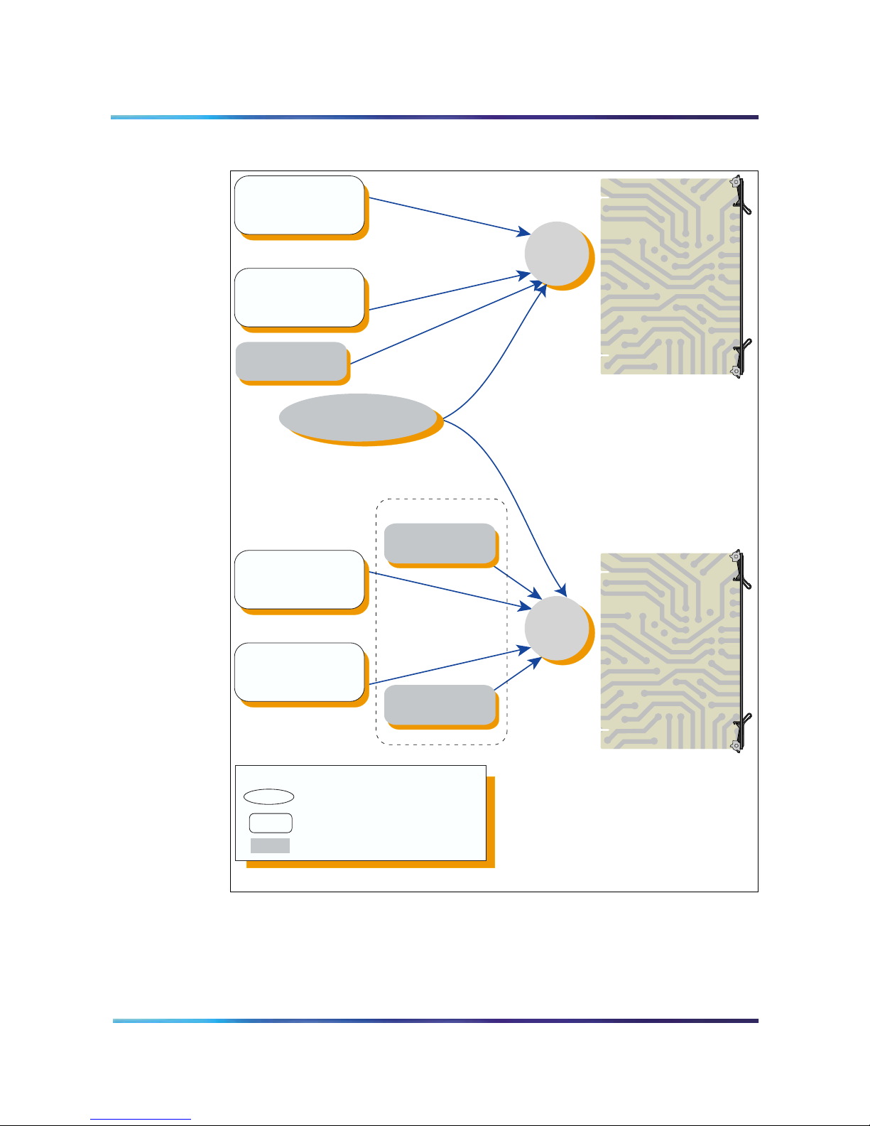
Test this out
Meridian 1, Succession 1000, Succession 1000M
Meridian Integrated Conference Bridge
Service Implementation Guide
Document Number: 553-3001-358
Product Release: MICB 3
Document Release: Standard 1.00
Date: October 2003
Copyright © 2003 Nortel Networks
All Rights Reserved
Produced in Canada
Information is subject to change without notice. Nortel Networks reserves the right to make changes in design or components as
progress in engineering and manufacturing may warrant. This equipment has been tested and found to comply with the limits for a
Class A digital device pursuant to Part 15 of the FCC rules, and the radio interference regulations of Industry Canada. These limits
are designed to provide reasonable protection against harmful interference when the equipment is operated in a commercial
environment. This equipment generates, uses and can radiate radio frequency energy, and if not installed and used in accordance
with the instruction manual, may cause harmful interference to radio communications. Operation of this equipment in a residential
area is likely to cause harmful interference in which case the user will be required to correct the interference at their own expense.
SL-1, Meridian 1, and Succession are trademarks of Nortel Networks.


Revision history
October 2003
Standard 1.00. This document is a new document for Succession 3.0.
It was created to support a restructuring of the Documentation Library.
This document contains information previously contained in the
following legacy document, now retired: Meridian Integrated
Conference Bridge: Description, Installation, Administration, and
Maintenance (553-3001-102, 555-4001-135).
Page 5 of 208
Meridian Integrated Conference Bridge Service Implementation Guide

Page 6 of 208
553-3001-358 Standard 1.00 October 2003

Contents
About this document 9
Product description 15
Engineering guidelines 31
Installation and configuration 41
Page 7 of 208
Purpose 15
MICB description 15
Hardware overview 19
MICB operation 24
Purpose 31
System requirements 31
System compatibility 33
Automatic call distribution resource allocation 33
LAN configuration 35
Purpose 41
Getting started 41
Succession 1000M, Succession 1000, and Meridian 1 configuration 42
Meridian SL-100 configuration 51
MICB installation and configuration procedures 61
MICB Installation Wizard 68
Browser User Interface 77
Purpose 77
Overview 77
Scheduling BUI 83
Chairperson operations 93
Administration BUI 98
Telephone User Interface 127
Purpose 127
Overview 127
TUI operation during an active conference 128
TUI services 138
Meridian Integrated Conference Bridge Service Implementation Guide

Page 8 of 208
Maintenance 143
Reports 165
Upgrades 183
Purpose 143
Maintenance overview 143
Diagnostic tools 145
CLI command summary 149
MICB fault isolation and correction 152
Error message handling 154
Backup and restore procedures 158
Purpose 165
Overview 165
Short Connection Report 167
Meetings Log Report 168
Overbooking Report 170
Billing Report 172
Maintenance (Error) Report 179
Purpose 183
Overview 183
Planning for an upgrade 185
Upgrade procedures 186
Appendix A: Password security 193
Purpose 193
Access permissions 194
Unsuccessful login attempt handling 195
Password parameters summary 196
Reset passwords 197
Appendix B: Product integrity 201
Purpose 201
Environmental specifications 201
Regulatory standards 202
List of terms 205
553-3001-358 Standard 1.00 October 2003

About this document
This document is a global document. Contact your system supplier or
your Nortel Networks representative to verify that the hardware and
software described are supported in your area.
Subject
The subject of this document is the installation, configuration,
operation, and maintenance of the Meridian Integrated Conference
Bridge (MICB) as a part of the overall system. The MICB card allows
you to schedule and configure multiple simultaneous conferences.
You can install the MICB card in Succession 1000M, Succession 1000,
Meridian 1, or Meridian SL-100 systems. In the majority of places the
MICB operates the same way regardless of the system in which you
install it. When the information differs between systems, this guide
contains separate sections for the Meridian SL-100 and the
Succession 1000M, Succession 1000, and Meridian 1 (for example,
configuration information).
Page 9 of 208
Note on legacy products and releases
This NTP contains information about systems, components, and
features that are compatible with Succession 3.0 Software. For more
information on legacy products and releases, click the
Technical Documentation link under Support on the Nortel Networks
home page:
http://www.nortelnetworks.com/
Applicable systems
This document applies to the following systems:
• Meridian 1 Option 11C Chassis
• Meridian 1 Option 11C Cabinet
• Meridian 1 Option 51C
• Meridian 1 Option 61
Meridian Integrated Conference Bridge Service Implementation Guide

Page 10 of 208
• Meridian 1 Option 61C
• Meridian 1 Option 61C CP PII
• Meridian 1 Option 81
• Meridian 1 Option 81C
• Meridian 1 Option 81C CP PII
• Succession 1000
• Succession 1000M Cabinet
• Succession 1000M Chassis
• Succession 1000M Half Group
• Succession 1000M Single Group
• Succession 1000M Multi Group
Note that memory upgrades may be required to run Succession 3.0
Software on CP3 or CP4 systems (Options 51C, 61, 61C, 81, 81C).
System migration
When particular Meridian 1 systems are upgraded to run
Succession 3.0 Software and configured to include a Succession
Signaling Server, they become Succession 1000M systems. Table 1
lists each Meridian 1 system that supports an upgrade path to a
Succession 1000M system.
Table 1
Meridian 1 systems to Succession 1000M systems (Part 1 of 2)
This Meridian 1 system...
Meridian 1 Option 11C Chassis Succession 1000M Chassis
Meridian 1 Option 11C Cabinet Succession 1000M Cabinet
Meridian 1 Option 51C Succession 1000M Half Group
Meridian 1 Option 61 Succession 1000M Single Group
Meridian 1 Option 61C Succession 1000M Single Group
Meridian 1 Option 61C CP PII Succession 1000M Single Group
Meridian 1 Option 81 Succession 1000M Multi Group
553-3001-358 Standard 1.00 October 2003
Maps to this
Succession 1000M system

Page 11 of 208
Table 1
Meridian 1 systems to Succession 1000M systems (Part 2 of 2)
Maps to this
This Meridian 1 system...
Succession 1000M system
Meridian 1 Option 81C Succession 1000M Multi Group
Meridian 1 Option 81C CP PII Succession 1000M Multi Group
Note the following:
• When an Option 11C system is upgraded to run Succession 3.0
Software, that system becomes a Meridian 1 Option 11C Cabinet.
• When an Option 11C Mini system is upgraded to run
Succession 3.0 Software, that system becomes a Meridian 1
Option 11C Chassis.
For more information, see one or more of the following NTPs:
• Small System: Upgrade Procedures (553-3011-258)
• Large System: Upgrade Procedures (553-3021-258)
• Succession 1000 System: Upgrade Procedures (553-3031-258)
Intended audience
This document is intended for system administrators and installers.
Conventions
Terminology
In this document, the following systems are referred to generically as
“system”:
• Meridian 1
• Succession 1000
• Succession 1000M
The following systems are referred to generically as “Small System”:
• Succession 1000M Chassis
• Succession 1000M Cabinet
• Meridian 1 Option 11C Chassis
• Meridian 1 Option 11C Cabinet
Meridian Integrated Conference Bridge Service Implementation Guide

Page 12 of 208
The following systems are referred to generically as “Large System”:
• Meridian 1 Option 51C
• Meridian 1 Option 61
• Meridian 1 Option 61C
• Meridian 1 Option 61C CP PII
• Meridian 1 Option 81
• Meridian 1 Option 81C
• Meridian 1 Option 81C CP PII
• Succession 1000M Half Group
• Succession 1000M Single Group
• Succession 1000M Multi Group
The call processor in Succession 1000 and Succession 1000M
systems is referred to as the “Succession Call Server”.
Related information
This section lists information sources that relate to this document.
NTPS
The following NTPs are referenced in this document:
• Transmission Parameters (553-3001-182)
• Features and Services (553-3001-306)
• Software Input/Output: Administration (553-3001-311)
• Call Detail Recording: Description and Formats (553-3001-350)
• Large System: Planning and Engineering (553-3021-120)
• Large System: Maintenance (553-3021-500)
• Succession 1000 System: Installation and Configuration
(553-3031-210)
• Succession 1000 System: Maintenance (553-3031-500)
If you are installing the MICB in a Meridian SL-100, see the following
documents for additional information:
• IPE Reference Manual (555-4001-129)
• Alarm Clearing Procedures (555-4031-543)
• Routine Maintenance Procedures (555-4031-546)
553-3001-358 Standard 1.00 October 2003

Online
CD-ROM
Page 13 of 208
• Card Replacement Procedures (555-4031-547)
• Log Report Reference Manual (555-4031-840)
The following documents apply to all platforms:
• Meridian Integrated Conference Bridge User Guide (P0989944)
shows end users how to schedule and manage a conference using
either the Telephone User Interface or the Browser User Interface.
• Meridian Integrated Conference Bridge Quick Reference Card
(P0989945) provides a list of Telephone User Interface Commands;
comes in a package of 20.
To access Nortel Networks documentation online, click the Technical
Documentation link under Support on the Nortel Networks
homepage:
http://www.nortelnetworks.com/
To obtain Nortel Networks documentation on CD-ROM, contact your
Nortel Networks customer representative.
Meridian Integrated Conference Bridge Service Implementation Guide

Page 14 of 208
553-3001-358 Standard 1.00 October 2003

Product description
Purpose
This chapter describes the functional and physical characteristics of the
Meridian Integrated Conference Bridge (MICB) Release 3. Technicians
can install the MICB Intelligent Peripheral Equipment (IPE) card in a
Succession 1000M, Succession 1000, Meridian 1, or Meridian SL-100.
The chapter contains the following sections:
• “MICB description” on page 15 – describes the MICB card and
the role it plays in conference calls. Summarizes MICB features and
services.
• “Hardware overview” on page 19 – describes the hardware
components of the MICB system.
• “MICB operation” on page 24 – shows how MICB conferences
operate.
MICB description
Conference administration
The MICB card allows users to schedule and administer multiple
simultaneous conferences. Schedule conferences based on
time-of-day, duration of each conference, and number of individuals
(conferees) participating in, or ports allocated, for each conference.
Schedule a conference using either of the following:
Page 15 of 208
• Browser User Interface – point and click web-page application
• Telephone User Interface – telephone keypad entries
The MICB card provides announcements and tones that relate to
specific events during conferences. These events include the following:
• advising the chairperson and conferees of the status of the
conference connection
• indicating when a conferee joins or leaves the conference, and
• warning the chairperson and the conferees when the conference is
about to expire.
Meridian Integrated Conference Bridge Service Implementation Guide

Page 16 of 208
Technicians can install multiple MICB cards into a single Intelligent
Peripheral Equipment (IPE) module, a Succession 1000M or
Meridian 1 Option 11C Cabinet shelf, or a Succession 1000 Media
Gateway slot. Each MICB card can operate independently, providing up
to 32 ports for a single conference. The MICB card can support up to
ten simultaneous, separate conferences.
Each MICB card supports up to 200 users.
When users establish a single-card conference, they use the 32 ports
on the card. If two conferences are held at the same time, they need to
share the 32 ports. For example, if one user sets up a 10-port
conference, the other can set up a 22-port conference.
Technicians can connect two MICB cards to provide up to 62 ports for
a single conference. In dual mode, there can be only one dual-card
meeting per pair of cards.
The MICB supports several simultaneous conferences. The number of
conferences depends on the number of MICB ports available and the
number of participants (conferees) in each conference. The MICB
supports the following:
• maximum number of participants as follows:
— single-card: 32 participants
— dual-card: 62 participants (unless Chairperson Control over a
Dual-card Meeting is activated, in which case it is 60
participants)
• any number of conferences (up to 10) with one or more participants
in each conference
The MICB communicates with the system software by emulating a
digital line card, which allows existing software to control the operation
of the MICB. Configure each MICB port as an Automatic Call
Distribution (ACD) M2616 digital telephone set.
System overview
The MICB comes as a single card, or a pair of cards if additional ports
are required to support a dual-card meeting. Each card stands alone,
even in the dual-card configuration. For dual-card meetings, the
553-3001-358 Standard 1.00 October 2003

primary card uses ports on the secondary card. The following rules
apply:
• Each card (that is, the primary and secondary) has its own set of
users. There is no “common list” for both cards.
• To schedule a conference, the user logs into the card in which their
account is defined. If the user has two accounts, one on each card,
they must try each card separately to find available resources for the
conference. There is no automatic pooling between cards.
• A user or super-user can have accounts on many cards at a
company (that is, a customer can have one person who administers
multiple bridges for their company).
• Dual-card conferences can only be scheduled by users on the
primary card.
MICB conference feature summary
The MICB:
• Allows volume control by conference participants.
• Offers customized conference-specific greetings.
Page 17 of 208
• Enables users to acquire and release chairperson control while in a
conference.
• Delivers pre-meeting and post-meeting participants notifications.
• Allows one chairperson per conference.
• Offers optional chairperson control on the secondary card of a
dual-card conference.
• Provides for one or more permanent bridge configurations.
• Supports multiple conferences simultaneously.
• Provides chairperson commands during an active conference.
• Provides conferee commands during an active conference.
• Allows conference extension beyond the scheduled time.
• Issues a 10-minute warning, before the conference termination.
• Supports multiple languages, including N.A. English, Spanish,
French, Brazilian Portuguese, L.A. Spanish, Mandarin, Japanese,
Korean, U.K. English, French, German, and Italian.
• Provides conference password security, requiring the chairperson
and/or the conferees to enter a Dual-Tone Multifrequency (DTMF)
password before entering the conference.
• Automatically starts and terminates conferences based on
reservations scheduled in advance.
Meridian Integrated Conference Bridge Service Implementation Guide

Page 18 of 208
• Provides Group Call with smart retry.
• Provides the ability to reserve a port in each conference for the
• Provides “Block scheduling” for recurrent conferences, up to one
• Offers an over-booking option, enabling the administrator to allocate
• Provides an emergency bridge option, which creates a permanent
• Provides automatic conference expansion, allowing additional
• Provides entry and exit indications – provides four options to
chairperson.
year in advance and up to 30 iterations of recurrent conferences.
up to 125% of port resources (based on the idea that most
conferences are scheduled with more ports than are required).
bridge that automatically dials a pre-determined list of DNs when
someone dials the emergency bridge DN. The emergency bridge
does not support the dual-card configuration.
conferees to join the conference. For the expansion to work, the
ports hosting the additional conferees must be both unassigned and
available.
indicate the entry and exit of a conference participant:
— entry by name, exit by name
— entry by name, exit by tone
— entry by tone, exit by tone
— silent entry and exit
• Allows the first conferee joining the conference to turn off and turn
on conference music.
• Controls access to the conference in progress by monitoring the
maximum number of scheduled attendees at each conference.
• Manages time and date for scheduled conferences and reserves
ports for each conference.
• Provides recorded announcements to conferees who attempt to
enter a meeting too early or after a meeting has ended.
• Issues audible responses to conferees based on the conference
activity.
• Allows recording of a brand line (custom) greeting to replace
standard greeting.
• Provides a scheduling display that indicates meeting reference
number and whether a custom greeting has been created.
• Provides scheduling receipts e-mailed to users (receipt includes the
direct meeting access DN or the single DN access DN.
553-3001-358 Standard 1.00 October 2003
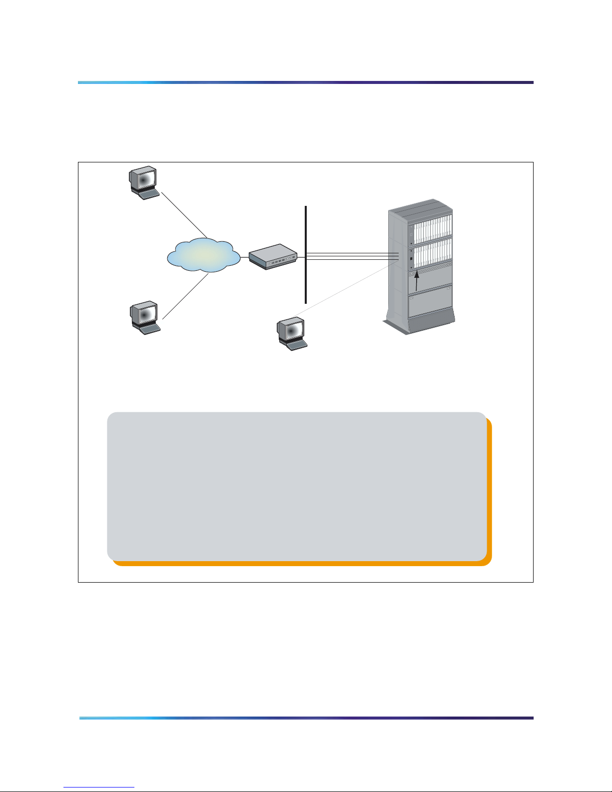
Hardware overview
2
Figure 1 shows an MICB system.
Figure 1
MICB system composition
PC Client
running Netscape
or Explorer
Intranet or
Internet
Router
Page 19 of 208
TCP/IP
LAN
LAN-to-Switch
Links
MICB 3
card(s)
PC Client
running Netscape
or Explorer
CRT
(for initial
setup only)
Intelligent Peripheral
Equipment (IPE) Module
1. You install up to six MICB 3 cards in an IPE shelf of the system. Each of the
MICB cards serves a specific set of users.
2. You connect cards to the corporate Intranet/Internet through a TCP/IP Ethernet
LAN, which is a 10BaseT physical connection.
3. You connect a CRT or Terminal Emulator directly to the serial port of the MICB 3.
You require this terminal for initial installation only. You perform all administration
and maintenance activities remotely.
4. Users and administrators access the cards from their desktops, which can be on
the global internet behind a firewall.
5. MICB 3 can co-exist with MICB 2 on the same switch, with or without the MICB 2
server. There is no interaction between MICB 2 and MICB 3.
553-AAA071
MICB hardware design characteristics
The MICB occupies one slot in an IPE module (Succession 1000M
Cabinet or Meridian 1 Option 11C Cabinet shelf, or Succession Media
Meridian Integrated Conference Bridge Service Implementation Guide

Page 20 of 208
Gateway slot in the Succession 1000). The MICB card has the following
hardware interface characteristics:
• Uses the microprocessor unit (MPU) based on the 25MHz
• Uses standard interface buses and personal computer memory
• Accesses all 32 DS-30X voice/signaling timeslots.
• Provides echo cancelling and automatic gain control.
• Supports both the A-law and the m-law signal coding/decoding.
• Emulates an M2616 digital telephone set on each MICB port.
• Supports Card-LAN interfaces.
• Performs X12 signaling protocol messages for input/output.
• Uses digital signal processor (DSP) for conferencing and DTMF
MC68EN360 Integrated Communications Controller.
card international association (PCMCIA) cards and handles files
that are compatible with MS-DOS operating system on the PCMCIA
storage device.
detection.
• The DSP firmware:
— Analyzes the loudness off all received signals continuously and
selects the two loudest signals to be the active speakers.
— Handles two-way conversation in conferences with three to 62
conferees.
— Normalizes the pulse code modulation (PCM) input samples.
— Provides gain control on all output samples.
— Provides software upgrades using a PCMCIA Flash card.
• Provides self-tests of internal hardware components and allows
card monitoring and maintenance through the maintenance port;
provides enable/disable capabilities similar to existing system
cards.
• Provides one RS-232 serial port for administration and maintenance
access.
• Provides enhanced Call Detail Recording (CDR –
Succession 1000M, Succession 1000, and Meridian 1 only) and
billing options.
• Provides an optional Ethernet interface over a Maintenance
interface.
553-3001-358 Standard 1.00 October 2003
• Provides a Command Line Interface (CLI) accessible by direct
connection, modem, telnet, or BUI emulation for performing OA&M
functions.
• Enables the reservation of one port on each card for TUI-only
interaction.
• Provides an embedded web-based server.
• Provides a customized MICB BUI login window.
• Offers automatic backup. Backup configurations can be e-mailed to
a predefined e-mail address.
Table 2 describes each hardware component of the MICB application.
These components connect the MICB to the local or remote
maintenance terminal.
Table 2
MICB hardware list
Component Description
Page 21 of 208
NT5D51AC or
higher MICB card
NT5D62FA or later
PCMCIA hard drive
card
NT5D52AC
Ethernet Adapter
card (for IPE module
installation)
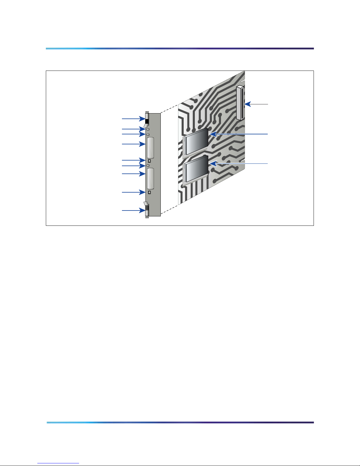
MICB card description
The MICB card has two PCMCIA sockets. PCMCIA hard drive cards
store the MICB voice prompts and firmware code. The MICB comes
with the PCMCIA hard drive. The bottom socket houses the PCMCIA
hard drive card that contains the current firmware and customer data.
Use the top socket to upgrade the firmware, and to backup and restore
customer data.
Figure 2 on page 22 shows the component side of the MICB card and
the faceplate. The component side shows the DRAM and the PCMCIA
socket locations. The faceplate shows the card LED and the PCMCIA
activity light-emitting diode (LED) indicators and the slot locations for
PCMCIA cards.
An IPE card that provides bridge and conference scheduling
for up to 10 simultaneous conferences.
This PCMCIA card contains the MICB software and
configuration. Install the PCMCIA card in the lower PCMCIA
drive.
Install this adapter card on the IPE module I/O panel only if
connecting the MICB to Ethernet.
NT5D52BC for Succession 1000, Succession 1000M
Cabinet, and Meridian 1 Option 11C Cabinet.
Meridian Integrated Conference Bridge Service Implementation Guide
Page 22 of 208
Figure 2
MICB card
SIMM Sockets
Lock Latch
Maintenance LED
PCMCIA Activity LED
Type II/III PCMCIA Slot
(for firmware upgrades and
backing up and restoring data)
PCMCIA Ejector
PCMCIA Activity LED
Type II/III PCMCIA Slot
(contains configuration and
application software)
PCMCIA Ejector
Lock Latch
The MICB faceplate provides the following:
Maintenance LED – The MICB faceplate provides a red LED to
indicate the enabled/disabled status of the card and to indicate the
self-testing result during power up or card insertion into an operating
system. This LED indicates the following:
• The LED is lit when the MICB card is disabled.
MICB
PCMCIA Socket
PCMCIA Hard
Drive Card
G100010
• The LED is off when the MICB card is enabled and ready for use.
• The LED blinks three times, runs software from the PCMCIA, then
blinks three times again and stays on. The LED remains on until the
software is enabled when the MICB card successfully completes the
self-test.
PCMCIA activity indicator LEDs – These LEDs are next to the
PCMCIA slots and indicate the following:
• The LED is lit when the PCMCIA card is disabled.
• The LED is off when the PCMCIA card is enabled and ready for use.
• The LED blinks when the PCMCIA card is in use.
553-3001-358 Standard 1.00 October 2003

Type II/III PCMCIA slots – The MICB faceplate provides two Type II/III
PCMCIA card slots. These slots house the PCMCIA cards. Install the
PCMCIA hard drive card that stores voice prompts and firmware code
in the lower slot. Use the upper slot for upgrading the firmware, and
backing up and restoring customer data.
External equipment
VT100 type terminal
Use a VT100 terminal for initial card configuration. After initial card
configuration, use the BUI to perform operations, administration and
maintenance (OA&M). Connect the terminal to the MICB RS-232
interface using one of the following methods:
• Direct connections:
— directly to the IPE module I/O panel
— directly to the DB-9 connector on the NT5D52 Ethernet Adapter
card installed on the I/O panel
• Remote connections:
— to the IPE module I/O panel through a modem connection
Page 23 of 208
The terminal interface must be set at 9600 baud, 8 data bits, 1 stop bit,
and no parity. The flow control is hard wired (do not use XON/XOFF
flow control).
Ethernet application
MICB Ethernet use has the following characteristics:
• The MICB Ethernet connection is separated from the external LAN
traffic by a firewall.
• The Ethernet Adapter connection for MICB is NT5D52AA for the IPE
module application.
• The Ethernet provider assigns the IP address for the MICB. Enter
the IP address from the Maintenance terminal.
• To access the MICB CLI over the Ethernet, use a TELNET client on
a PC workstation or in the LAN.
Meridian Integrated Conference Bridge Service Implementation Guide

Page 24 of 208
MICB operation
The MICB provides flexibility in configuring conferences. Configure
conferences as follows:
• pre-scheduled conferences with a fixed number of ports and
• pre-scheduled conferences with a variable numbers of ports, where
• permanent bridges with fixed numbers of ports that can be used
The minimum duration of a conference is 15 minutes and the maximum
duration of a time-limited conference is 12 hours. The conference
starting time and duration can be scheduled in increments of 15
minutes.
The MICB card continuously monitors the audio signal level received
from each conferee and selects the two loudest signals for
transmission. The two loudest signals are summed and inserted into
the PCM sample prior to their transmission to other conferees. This
implementation of the two loudest signals improves the interrupting
capability of a conference connection and allows normal two-way
conversation that all conferees can hear.
start/stop times
ports are added when required (if available) and subtracted by the
system automatically as conferees leave the conference
without pre-scheduling the conference
In addition to the conferee timeslots, the MICB provides a timeslot
between the MPU and the DSP. This timeslot transmits message
prompts, entry and exit tones, or both that the system broadcasts to all
conferees when requested by the MPU.
The MICB uses ACD features to route external incoming trunk and local
line conferees to their appropriate conferences. The ACD features
provide queuing, chairperson features, and event reporting for each
conference.
The ACD features used by the MICB card provide the following:
• easy software configuration
• incoming calls, announcement on arrival, call management, and
reporting queues
• operational statistics reports
• enhanced call routing
553-3001-358 Standard 1.00 October 2003

Figure 3 shows the call routing for three conferences and shows the
DEF
MNO
WXY
ABC
JKL
TUV
GHI
PRS
Rls
HOLD
DEF
MNO
WXY
ABC
JKL
TUV
GHI
PRS
Rls
HOLD
DEF
MNO
WXY
ABC
JKL
TUV
GHI
PRS
Rls
HOLD
conference chairperson access DN for each conference. The figure
also shows the ACD DN for the ACD queue that controls the path of all
ports on an MICB card. The right-hand side of the figure shows the
distribution of MICB ports as ACD agents.
Figure 3
Call routing with chairperson access
Page 25 of 208
Trunk calls
DID trunk
Port 0
Port 1
Port 2
Port 3
Local calls
Rls
HOLD
Rls
DEF
ABC
3
21
HOLD
DEF
ABC
MNO
JKL
GHI
3
21
6
5
4
WXY
TUV
PRS
MNO
JKL
GHI
9
8
7
6
5
4
WXY
TUV
PRS
0
9
8
7
0
Rls
HOLD
Rls
DEF
ABC
3
21
HOLD
DEF
ABC
MNO
JKL
GHI
3
21
6
5
4
WXY
TUV
PRS
MNO
JKL
GHI
9
8
7
6
5
4
WXY
TUV
PRS
0
9
8
7
0
Rls
HOLD
Rls
DEF
ABC
3
21
HOLD
DEF
ABC
MNO
JKL
GHI
3
21
6
5
4
WXY
TUV
PRS
MNO
JKL
GHI
9
8
7
6
5
4
WXY
TUV
PRS
0
9
8
7
0
Main DNs
3001
3101
3002
3102
ACD DN
4144
3003
3103
Intelligent Peripheral
Equipment
(IPE) Module
Note:
This figure applies to the direct meeting access option.
Chairperson
DNs
ACD Queue DN
for all ports of an
MICB card
For single-number access, the Main DNs and Chairperson DNs
(that is, 3001-3103) are replaced by one DN only.
ACD Agent
MICB Port 0
ACD Agent
MICB Port 1
ACD Agent
MICB Port 2
ACD Agent
MICB Port 3
ACD Agent
MICB Port 4
ACD Agent
MICB Port 5
ACD Agent
MICB Port 31
G100008
Join the conference using the direct meeting access method
Assign a main DN and a chairperson DN, for each conference. The
main DN is the number the conferees dial to get into the conference and
the chairperson DN is the number the chairperson dials. Configure the
DNs in the system when installing the MICB card. The total number of
DNs is equal to two times the number of simultaneous conferences. For
example, 10 simultaneous conferences require 20 DNs: 10 main DNs
and 10 chairperson DNs.
When several conferences occur simultaneously in the same MICB
card, the conferee dials the DN assigned to a specific conference. The
MICB card identifies the dialed DN and routes the conferee to the
appropriate conference represented by that specific DN. The system
Meridian Integrated Conference Bridge Service Implementation Guide

Page 26 of 208
assigns all ports on the MICB card to the appropriate conference
through the ACD DN assigned to that MICB card. The chairperson dials
the chairperson DN to a specific conference. This number is different
from the DN dialed by the conferees for the same conference.
The MICB performs DTMF detection on MICB ports identified as
chairperson ports. DTMF detects when conferees enter a conference
password. A conference can start without the chairperson. If all
allocated ports for a conference are taken up with conferees, the
chairperson cannot join the conference, unless a port is specifically
reserved for the chairperson. The chairperson can also join if the
system allows conference expansion and there are free, un-scheduled
(floating) ports available.
The first conferee joining the conference hears an announcement
indicating that no other conferee has joined the conference, followed by
60 seconds of music. The system repeats the announcement with 60
seconds of music, until another conferee joins the conference.
Join the conference using the single DN access method
The single DN access method to all meetings provides users with a
alternative method of accessing the MICB. This feature reduces the
amount of Direct Inward Dialing (DID) numbers that have to be
configured in the switch and provides the following benefits:
• Saves 20 DID numbers from the customer’s DID range.
• Saves 20 ACD or Phantom DNs in the system thereby providing a
cost savings.
• Simplifies installation as there is no DN pair configuration.
• Saves work if a change the numbering plan is required in the
system.
The only trade-off is that callers have an additional step when
accessing a meeting (that is, after dialing the single-access DN, they
must enter the chairperson, or meeting, DN of their specific meeting).
Figure 4 on page 27 shows the DN configuration for single DN access
with one MICB card.
553-3001-358 Standard 1.00 October 2003
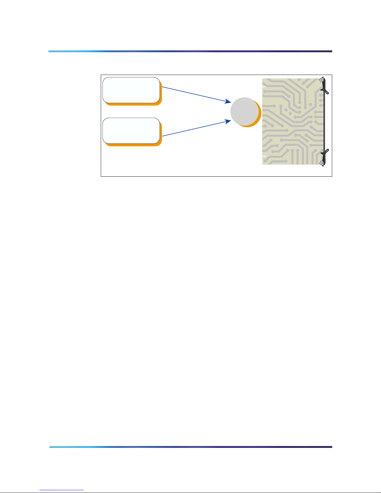
Figure 4
Single DN access method (one MICB card)
Page 27 of 208
Single-access
DN for conferences
dial-in
TUI services dial-in
(scheduling,
recording)
Night Call Forward
Night Call Forward
MICB
ACD
DN
MICB Card
G100079
The DNs on the left in Figure 4 can be Phantom DNs or CDNs, instead
of ACD DNs. The DNs must be DID numbers.
In a dual-card system, each card requires its own single-access DN. In
a dual-card set, conferences that span the two cards do not support the
single DN access method. However, in a dual-card set, simple
conferences that use only one card support the single DN access
method.
Figure 5 on page 28 shows the DN configuration in a system for the
single DN access method when the system uses two MICB cards.
Single DN access requires one DN, instead of the separate 10 DNs
required with direct meeting access.
The figure shows a configuration that supports the following:
• Simple conference contained in the primary MICB – participants dial
the single-access DN at the top of the figure.
• Simple conferences contained on the secondary MICB –
participants dial the single-access DN at the bottom of the figure.
• Meetings spanning both cards – participants dial the “Dual meeting
main DN” in the middle of the figure and the chairperson dials the
“Dual meeting chairperson DN”. The figure shows that dual-card
meetings do not use the single-access DNs.
Meridian Integrated Conference Bridge Service Implementation Guide
Page 28 of 208
Figure 5
Single DN access method (two MICB cards)
TUI services dial-in
chairperson DN
Single-access
DN for simple
meetings
(scheduling,
recording)
Dual meeting
Dual meeting main
DN ACD time overflow
Hidden from end users
MICB
ACD
DN
Primary
MICB Card
Voice link
DN
Single-access
DN for simple
meetings
Secondary
MICB Card
G100080
TUI services dial-in
(scheduling,
recording)
Legend
ACD DN
ACD DN , CDN or Phantom DN
For dual meeting
MICB
ACD
DN
Dual callers
transfer DN
Note: All DNs on the left side of the figure must be DID numbers.
Single DN access is mutually exclusive from the direct meeting access
method in an MICB card or card pair. Configure the card for one access
553-3001-358 Standard 1.00 October 2003

method; the system does not support combinations on the card or card
pair.
Callers to all meetings access the MICB by dialing one common fixed
number. The MICB prompts the caller for the meeting or chairperson
DN to enter the required meeting. In this mode of operation, configure
the single-access DN in the system and MICB only. Access DN pairs
are pre-coded in the card.
Expand the conference
Conference expansion allows the system to increase the number of
conferees if there are remaining MICB ports that are both unassigned
and unused. Allow or deny conference expansion for each conference
using the Browser User Interface (BUI) (see the “Add ports as needed
field” in the “Scheduling window” on page 86).
When reserving the MICB ports for each simultaneous conference, the
system does not tag ports for a specific conference. The MICB counts
the number of reserved ports and compares these against the total
number of ports provided by the MICB card. The MICB then makes sure
that the reserved ports do not exceed the total number of ports provided
by the MICB card.
Page 29 of 208
If additional (non-scheduled) callers try to join a conference, but there
are no floating ports, or the system locks out additional conferees, the
MICB card issues an overflow tone. The system then disconnects the
call.
If the system releases un-scheduled (floating) ports from a conference,
they are immediately available to be used by other conferences that
have the expansion feature enabled.
End the conference
When scheduling a conference, indicate the number of ports, start time,
and duration of that conference. The conference ends based on the
start time and conference duration. Ten minutes before the end of a
conference, the MICB card issues an announcement warning the
conferees that the conference terminates in 10 minutes.
When the conference time expires, the MICB card issues the final
warning to the conferees. The MICB sends a release message to the
system for all associated MICB ports. These ports become available for
the next planned conference. If there is no other scheduled conference,
they become floating ports which the system does not reserve for any
conference. Floating ports are available to expand conferences in
progress.
Meridian Integrated Conference Bridge Service Implementation Guide

Page 30 of 208
Conferees can exit a conference at any time. The MICB detects when
a conferee exits the conference. If enabled, the MICB announces the
conferee’s name. When one conferee is on the conference, the system
issues an announcement that only one conferee is present, followed by
60 seconds of music. The system repeats this announcement and the
music, until at least one more conferee joins in, or the MICB terminates
the conference.
Note: A conference can begin and end two minutes before the
defined time. This feature allows the system to close all terminating
conferences two minutes earlier and start all scheduled conferences
immediately after closing the terminating conferences. This feature is
important when terminating and starting conferences use some of
the same DNs.
553-3001-358 Standard 1.00 October 2003
 Loading...