

Nortel SR1001, SR1001S Installation Manual

Part No. 322004-A
March 2006
4655 Great America Parkway
Santa Clara, CA 95054
SR1001 Installation Guide
Nortel Secure Routers 1001 and 1001S
Software Release 8.3.5

Copyright © 2006 Nortel Networks. All rights reserved.
The information in this document is subject to change without notice. The statements, configurations, technical data, and recommendations
in this document are believed to be accurate and reliable, but are presented without express or implied warranty. Users must take full
responsibility for their applications of any products specified in this document. The information in this document is proprietary to Nortel
Networks.
The software described in this document is furnished under a license agreement and may be used only in accordance with the terms of that
license. The software license agreement is included in this document.
Trademarks
*Nortel, Nortel Networks, the Nortel logo, the Globemark, Unified Networks, and BayStack are trademarks of Nortel Networks.
Adobe and Adobe Reader are trademarks of Adobe Systems Incorporated.
Microsoft, Windows, and Windows NT are trademarks of Microsoft Corporation.
The asterisk after a name denotes a trademarked item.
Restricted rights legend
Use, duplication, or disclosure by the United States Government is subject to restrictions as set forth in subparagraph (c)(1)(ii) of the Rights
in Technical Data and Computer Software clause at DFARS 252.227-7013.
Notwithstanding any other license agreement that may pertain to, or accompany the delivery of, this computer software, the rights of the
United States Government regarding its use, reproduction, and disclosure are as set forth in the Commercial Computer Software-Restricted
Rights clause at FAR 52.227-19.
Statement of conditions
In the interest of improving internal design, operational function, and/or reliability, Nortel Networks reserves the right to make changes to
the products described in this document without notice.
Nortel Networks does not assume any liability that may occur due to the use or application of the product(s) or circuit layout(s) described
herein.
Portions of the code in this software product may be Copyright © 1988, Regents of the University of California. All rights reserved.
Redistribution and use in source and binary forms of such portions are permitted, provided that the above copyright notice and this
paragraph are duplicated in all such forms and that any documentation, advertising materials, and other materials related to such distribution
and use acknowledge that such portions of the software were developed by the University of California, Berkeley. The name of the
University may not be used to endorse or promote products derived from such portions of the software without specific prior written
permission.
SUCH PORTIONS OF THE SOFTWARE ARE PROVIDED “AS IS” AND WITHOUT ANY EXPRESS OR IMPLIED WARRANTIES,
INCLUDING, WITHOUT LIMITATION, THE IMPLIED WARRANTIES OF MERCHANTABILITY AND FITNESS FOR A
PARTICULAR PURPOSE.
In addition, the program and information contained herein are licensed only pursuant to a license agreement that contains restrictions on use
and disclosure (that may incorporate by reference certain limitations and notices imposed by third parties).
Nortel Networks software license agreement
This Software License Agreement (“License Agreement”) is between you, the end-user (“Customer”) and Nortel Networks Corporation and
its subsidiaries and affiliates (“Nortel Networks”). PLEASE READ THE FOLLOWING CAREFULLY. YOU MUST ACCEPT THESE
LICENSE TERMS IN ORDER TO DOWNLOAD AND/OR USE THE SOFTWARE. USE OF THE SOFTWARE CONSTITUTES YOUR
ACCEPTANCE OF THIS LICENSE AGREEMENT. If you do not accept these terms and conditions, return the Software, unused and in the
original shipping container, within 30 days of purchase to obtain a credit for the full purchase price.
“Software” is owned or licensed by Nortel Networks, its parent or one of its subsidiaries or affiliates, and is copyrighted and licensed, not
sold. Software consists of machine-readable instructions, its components, data, audio-visual content (such as images, text, recordings or
pictures) and related licensed materials including all whole or partial copies. Nortel Networks grants you a license to use the Software only
in the country where you acquired the Software. You obtain no rights other than those granted to you under this License Agreement. You are
responsible for the selection of the Software and for the installation of, use of, and results obtained from the Software.
1. Licensed Use of Software. Nortel Networks grants Customer a nonexclusive license to use a copy of the Software on only one
machine at any one time or to the extent of the activation or authorized usage level, whichever is applicable. To the extent Software is
SR1001 Installation Guide
Version 8.3.5

furnished for use with designated hardware or Customer furnished equipment (“CFE”), Customer is granted a nonexclusive license to use
Software only on such hardware or CFE, as applicable. Software contains trade secrets and Customer agrees to treat Software as confidential
information using the same care and discretion Customer uses with its own similar information that it does not wish to disclose, publish or
disseminate. Customer will ensure that anyone who uses the Software does so only in compliance with the terms of this Agreement.
Customer shall not a) use, copy, modify, transfer or distribute the Software except as expressly authorized; b) reverse assemble, reverse
compile, reverse engineer or otherwise translate the Software; c) create derivative works or modifications unless expressly authorized; or d)
sublicense, rent or lease the Software. Licensors of intellectual property to Nortel Networks are beneficiaries of this provision. Upon
termination or breach of the license by Customer or in the event designated hardware or CFE is no longer in use, Customer will promptly
return the Software to Nortel Networks or certify its destruction. Nortel Networks may audit by remote polling or other reasonable means to
determine Customer’s Software activation or usage levels. If suppliers of third party software included in Software require Nortel Networks
to include additional or different terms, Customer agrees to abide by such terms provided by Nortel Networks with respect to such third
party software.
2. Warranty. Except as may be otherwise expressly agreed to in writing between Nortel Networks and Customer, Software is provided
“AS IS” without any warranties (conditions) of any kind. NORTEL NETWORKS DISCLAIMS ALL WARRANTIES (CONDITIONS)
FOR THE SOFTWARE, EITHER EXPRESS OR IMPLIED, INCLUDING, BUT NOT LIMITED TO THE IMPLIED WARRANTIES OF
MERCHANTABILITY AND FITNESS FOR A PARTICULAR PURPOSE AND ANY WARRANTY OF NON-INFRINGEMENT. Nortel
Networks is not obligated to provide support of any kind for the Software. Some jurisdictions do not allow exclusion of implied warranties,
and, in such event, the above exclusions may not apply.
3. Limitation of Remedies. IN NO EVENT SHALL NORTEL NETWORKS OR ITS AGENTS OR SUPPLIERS BE LIABLE FOR
ANY OF THE FOLLOWING: a) DAMAGES BASED ON ANY THIRD PARTY CLAIM; b) LOSS OF, OR DAMAGE TO,
CUSTOMER’S RECORDS, FILES OR DATA; OR c) DIRECT, INDIRECT, SPECIAL, INCIDENTAL, PUNITIVE, OR
CONSEQUENTIAL DAMAGES (INCLUDING LOST PROFITS OR SAVINGS), WHETHER IN CONTRACT, TORT OR OTHERWISE
(INCLUDING NEGLIGENCE) ARISING OUT OF YOUR USE OF THE SOFTWARE, EVEN IF NORTEL NETWORKS, ITS AGENTS
OR SUPPLIERS HAVE BEEN ADVISED OF THEIR POSSIBILITY. The foregoing limitations of remedies also apply to any developer
and/or supplier of the Software. Such developer and/or supplier is an intended beneficiary of this Section. Some jurisdictions do not allow
these limitations or exclusions and, in such event, they may not apply.
4. General
a. If Customer is the United States Government, the following paragraph shall apply: All Nortel Networks Software available under
this License Agreement is commercial computer software and commercial computer software documentation and, in the event
Software is licensed for or on behalf of the United States Government, the respective rights to the software and software
documentation are governed by Nortel Networks standard commercial license in accordance with U.S. Federal Regulations at 48
C.F.R. Sections 12.212 (for non-DoD entities) and 48 C.F.R. 227.7202 (for DoD entities).
b. Customer may terminate the license at any time. Nortel Networks may terminate the license if Customer fails to comply with the
terms and conditions of this license. In either event, upon termination, Customer must either return the Software to Nortel
Networks or certify its destruction.
c. Customer is responsible for payment of any taxes, including personal property taxes, resulting from Customer’s use of the
Software. Customer agrees to comply with all applicable laws including all applicable export and import laws and regulations.
d. Neither party may bring an action, regardless of form, more than two years after the cause of the action arose.
e. The terms and conditions of this License Agreement form the complete and exclusive agreement between Customer and Nortel
Networks.
f. This License Agreement is governed by the laws of the country in which Customer acquires the Software. If the Software is
acquired in the United States, then this License Agreement is governed by the laws of the state of New York.
How to get help
This section explains how to get help for Nortel products and services.
Getting help from the Nortel web site
The best way to get technical support for Nortel products is from the Nortel Technical Support web site:
www.nortel.com/support
This site provides quick access to software, documentation, bulletins, and tools to address issues with Nortel products. More specifically, the
site enables you to:
• download software, documentation, and product bulletins
• search the Technical Support web site and the Nortel Knowledge Base for answers to technical issues
SR1001 Installation Guide
Version 8.3.5

• sign up for automatic notification of new software and documentation for Nortel equipment
• open and manage technical support cases
Getting help through a Nortel distributor or reseller
If you purchased a service contract for your Nortel product from a distributor or authorized reseller, contact the technical support staff for
that distributor or reseller.
Getting help over the phone from a Nortel Solutions Center
If you do not find the information you require on the Nortel Technical Support web site, and have a Nortel support contract, you can also get
help over the phone from a Nortel Solutions Center.
In North America, call 1-800-4NORTEL (1-800-466-7835).
Outside North America, go to the following web site to obtain the phone number for your region:
www.nortel.com/callus
Getting help from a specialist by using an Express Routing Code
An Express Routing Code (ERC) is available for many Nortel products and services. When you use an ERC, your call is routed to a
technical support person who specializes in supporting that product or service. To locate the ERC for your product or service, go to:
www.nortel.com/erc
SR1001 Installation Guide
Version 8.3.5

T
ABLE OF
C
1 ABOUT THIS GUIDE
Organization....................................................................................................................................... 2
Conventions ....................................................................................................................................... 3
Notices ........................................................................................................................................... 3
Documentation ................................................................................................................................... 4
About the Nortel Secure Router Documentation CD..................................................................... 4
Navigation .................................................................................................................................. 4
Printing Documents.................................................................................................................... 4
Related Nortel Guides .................................................................................................................... 4
2 PRODUCT INTRODUCTION
Overview............................................................................................................................................ 7
1001.................................................................................................................................................... 8
1001 Front Panel ............................................................................................................................ 8
1001 Back Panel............................................................................................................................. 8
1001 Serial ......................................................................................................................................... 10
1001S Front Panel.......................................................................................................................... 10
1001S Back Panel .......................................................................................................................... 10
ONTENTS
3 INSTALLATION
Site Preparation .................................................................................................................................. 13
Environment................................................................................................................................... 13
Power Requirements ...................................................................................................................... 14
Network Connection ...................................................................................................................... 14
Cables Required ............................................................................................................................. 14
Tools Required ............................................................................................................................... 15
Unpacking and Inspecting.................................................................................................................. 16
Wall-Mounting Option................................................................................................................... 17
Rack-Mounting Option .................................................................................................................. 18
Installing the 1001.............................................................................................................................. 19
Table Top Installation .................................................................................................................... 19
Wall-Mount Installation ................................................................................................................. 20
Rack-Mount Installation ................................................................................................................ 21
Network Connections......................................................................................................................... 22
Connecting the Ethernet Cable ...................................................................................................... 22
Connecting the WAN Cable .......................................................................................................... 22
Operator Interface .............................................................................................................................. 24
Local Management......................................................................................................................... 24
Remote Management ..................................................................................................................... 24
Console Messages .......................................................................................................................... 25
SR1001 Installation Guide
Version 8.3.5

4 CONFIGURATION
Logging In .......................................................................................................................................... 27
Command Tips ............................................................................................................................... 27
Ethernet Configuration Tip ............................................................................................................ 27
Changing Login Parameters ............................................................................................................... 29
Password......................................................................................................................................... 29
Administrator Account...................................................................................................................29
Secure Router Host Name .............................................................................................................. 29
Date and Time ................................................................................................................................ 30
Adding Users.................................................................................................................................. 31
Removing Users ............................................................................................................................. 31
Default Configuration ........................................................................................................................ 32
Installing the Software License Key .................................................................................................. 34
Switching Routing/IPMUX Modes ................................................................................................ 34
Boot Process ....................................................................................................................................... 35
Upgrading Secure Router Software.................................................................................................... 36
Before Downloading the T1000.Z File .......................................................................................... 36
Upgrading Software ....................................................................................................................... 37
Booting From a Network TFTP Server..............................................................................................38
Interface Configuration ...................................................................................................................... 41
Bundle Configuration......................................................................................................................... 42
Routing Configuration........................................................................................................................ 44
Compact Flash Configuration ............................................................................................................ 47
Saving Configurations........................................................................................................................ 47
5 TROUBLESHOOTING
Alarms and Secure Router Status ....................................................................................................... 49
WAN Statistics ............................................................................................................................... 49
Network Tests .................................................................................................................................... 50
Ping Test......................................................................................................................................... 50
Other Tests ..................................................................................................................................... 50
Loopback Test ............................................................................................................................ 50
BERT Test .................................................................................................................................. 50
Diagnostics Tips ................................................................................................................................. 51
General Symptoms ......................................................................................................................... 51
A SPECIFICATIONS
SR1001 Installation Guide
Version 8.3.5
Secure Router Specifications ............................................................................................................. 55
WAN Interfaces.............................................................................................................................. 56
LAN Interfaces ............................................................................................................................... 57
Cable Pinouts.................................................................................................................................. 58
MIBs................................................................................................................................................... 63

B COMPLIANCE AND STANDARDS
Compliance ........................................................................................................................................ 65
FCC Conformance ............................................................................................................................. 66
FCC Part 15.................................................................................................................................... 66
FCC Part 68.................................................................................................................................... 66
Incidence of Harm.......................................................................................................................... 66
Rights of the Telephone Company.................................................................................................67
Proper Disposal of Nortel Equipment ................................................................................................ 68
INDEX
SR1001 Installation Guide
Version 8.3.5

SR1001 Installation Guide
Version 8.3.5

F
IGURES
1 1001 Router Front Panel ............................................................................................................ 8
2 1001 Router Back Panel............................................................................................................. 8
3 1001 Router Front Panel ............................................................................................................ 10
4 1001 Router Back Panel............................................................................................................. 10
5 Chassis Air Flow ........................................................................................................................ 13
6 Ethernet Cable............................................................................................................................ 14
7 WAN Cable................................................................................................................................ 15
8 Required Tools ........................................................................................................................... 15
9 Items Shipped with the SR1001 ................................................................................................. 16
10 Wall-Mount Components...........................................................................................................17
11 Rack-Mount Components .......................................................................................................... 18
12 Table Top Installation ................................................................................................................ 19
13 Wall Mounting the SR1001 and SR1001S ................................................................................ 20
14 Rack Mounting the SR1001.......................................................................................................
15 Connecting the Ethernet Cable ................................................................................................. 22
16 Connecting the WAN Cable ..................................................................................................... 23
17 Connecting the Console Cable (Local Management) ................................................................ 24
18 Connecting a Modem for Remote Management ....................................................................... 24
19 Initial CLI Prompt ...................................................................................................................... 27
21
SR1001 Installation Guide
Version 8.3.5

SR1001 Installation Guide
Version 8.3.5

T
ABLES
1 Guide Organization: Chapters..................................................................................................... 2
2 Guide Organization: Appendices ................................................................................................ 2
3 Text Conventions ........................................................................................................................ 3
4 LED and Port Descriptions ......................................................................................................... 8
5 1001 Back-Panel Ports................................................................................................................ 9
6 LED and Port Descriptions ......................................................................................................... 10
7 1001 Back-Panel Ports................................................................................................................ 11
8 Ethernet Interface Default Configuration ................................................................................... 32
9 IP Default Configuration............................................................................................................. 32
10 T1 Interface Default Configuration............................................................................................. 33
11 E1 Interface Default Configuration............................................................................................. 33
12 Default Console Port Settings ..................................................................................................... 33
13 Compact Flash File Commands .................................................................................................. 47
14 BERT Test Patterns..................................................................................................................... 50
15 Common Symptoms and Actions ............................................................................................... 51
16 Environment, Hardware, Memory, and Power ........................................................................... 55
17 Performance Monitoring ............................................................................................................. 56
18 T1 WAN Interface ...................................................................................................................... 56
19 E1 WAN Interface ...................................................................................................................... 57
20 Specifications: Serial Interface ................................................................................................... 57
21 Specifications: V.35 Interface ..................................................................................................... 57
22 Specifications: Ethernet LAN Interface...................................................................................... 58
23 Miscellaneous.............................................................................................................................. 58
24 Pinouts: Nortel-to-Terminal Console Cable (DB-9)................................................................... 58
25 Pinouts: Ethernet Cable (RJ-45) ................................................................................................
26 Pinouts: WAN Cable (RJ-48C)................................................................................................... 59
27 DB-25 to RJ-45 Modem Adapter Pinouts................................................................................... 59
28 Pinouts: Serial Connector (DTE) ................................................................................................ 59
29 Pinouts: Serial Connector (DCE)................................................................................................ 60
30 Pinouts: V.35 Connector (DTE).................................................................................................. 61
31 Pinouts: V.35 Connector (DCE) ................................................................................................. 62
32 Standard MIBS............................................................................................................................ 63
33 Nortel Enterprise MIBs ............................................................................................................... 64
34 Regulatory and Compliance Standards ....................................................................................... 65
.59
SR1001 Installation Guide
Version 8.3.5

SR1001 Installation Guide
Version 8.3.5

1
A
BOUT
Detailed instructions are provided in this guide for installing, configuring, and
troubleshooting the Nortel Secure Router 1001 and 1001Serial (1001S). This guide is
designed for network managers, administrators, and technicians who are responsible for
the installation and management of networking equipment in Enterprise and Service
Provider environments. Knowledge of Telecom technologies and standards including T1, E1,
serial, and Ethernet is assumed.
This chapter provides information about the intended audience for this guide, how this
guide is organized, typographical conventions, the use of notices, and related
documentation.
T
HIS
G
UIDE
1
SR1001 Installation Guide
Version 8.3.5

2
CHAPTER
1
About This Guide Organization
Organization
The following tables describe the content and organization of this guide.
Table 1 Guide Organization: Chapters
Chapter Description
1 About This Guide - defines the user audience, and describes the organization of this guide, use of
special notices, and other Nortel user guides.
2 Product Introduction - provides a description of installation site requirements, and cables and
tools required for installing the SR1001.
3 Installation - describes the system front and back panels and how to install the SR1001.
Information is also provided about the operator interface, network cabling, and the operator
interface.
4 Configuration - describes system configuration, logging in, factory defaults, changing the default
5 Troubleshooting - provides information about network indicators, tests, and general
Table 2 Guide Organization: Appendices
Appendix Description
A Specifications - lists the electrical, physical, and networking characteristics of the SR1001. Cable
B Compliance and Standards - provides regulatory information and compliance information
password, upgrading software, and the boot process.
troubleshooting tips. A summary of common problems and solutions is also included.
pinout and related MIB file information is also provided.
applicable to the SR1001.
SR1001 Installation Guide
Version 8.3.5

Conventions
Notices
This guide uses the following typographical conventions:
Table 3 Text Conventions
Font Description
boldface font
screen font
Used for commands that you enter, words that you type, or keyboard keys that you press.
Used to display a screen capture.
Notice paragraphs alert you about issues that require your attention. The following paragraphs
describe the types of notices used in this guide.
NOTE: Notes provide tips and useful information regarding the installation and operation of Nortel
Secure Routers.
ESD: ESD notices provide information about how to avoid discharge of static electricity and subsequent
damage to Nortel Secure Routers.
3
CAUTION: Caution notices provide information about how to avoid possible service disruption or
damage to Nortel Secure Routers.
WARNING: Warning notices provide information about how to avoid personal injury when working
with Nortel Secure Routers.
SR1001 Installation Guide
Version 8.3.5

4
CHAPTER
1
About This Guide Documentation
Documentation
Nortel user guides, which are provided in portable document format (PDF), are included on
the Nortel Secure Router Documentation CD-ROM that ships with the SR1001. The PDF files are
also available on the Nortel website: www.nortel.com
To view PDF files, Adobe Acrobat® Reader® 4.0, or newer, must be installed on your
workstation. If you do not have the Adobe Acrobat Reader installed on your system, you can
obtain it free from the Adobe website: www.adobe.com
About the Nortel Secure Router Documentation CD
This product ships with a CD that includes the following documentation:
SR1001 Quick Start Guide
SR1001 Installation Guide
SR1001 Command Reference Guide
SR1001 Routing Guide
SR1001 Configuration Guide
SR1001 Web UI User Guide
Supported standard and enterprise MIBs
Feature summaries
SNMP trap descriptions with default configurations
.
Related Nortel Guides
Navigation
Upon inserting the Nortel Secure Router Documentation CD into your CD-ROM drive. Click a
link to open a pdf version of the target document. If you do not have Adobe Acrobat (version
4.0, or later) or Acrobat Reader installed on your PC, click the Adobe button on the navigation
screen to go to the Adobe website, where you can download a free copy of the Acrobat Reader
application.
If a browser session is not opened, click “Start\Run,” enter the drive letter of your CD-ROM
drive in the “Open” entry box, and click “OK.”
Printing Documents
To print any pdf document on the CD, follow this procedure.
1 Open the desired document by clicking the document link in the CD navigation window.
2 Click the “Printer” icon on the Adobe Acrobat tool bar.
3 In the “Windows Print” dialog box, select a local default printer in the “Printers” drop
down selection box.
4 Click “OK.”
In addition to this guide, the following list includes other available Nortel documentation:
Release Notes
Printed release notes provide the latest information. If release notes are provided
with your product, follow these instructions in addition to those provided in other
documentation.
SR1001 Quick Start Guide
This guide is designed to assist users with the initial installation and deployment of
the SR1001. The guide provides a brief overview of the installation and initial
configuration processes for the SR1001.
SR1001 Command Reference Guide
SR1001 Installation Guide
Version 8.3.5

This detailed guide provides a complete description of all Nortel command line
interface (CLI) commands.
SR1001 Routing Guide
This guide provides descriptions of commands available for Nortel implementation of
BGP (including BGP4), OSPF, RIP and other routing protocols.
SR1001 Configuration Guide
This guide provides example configurations.
SR1001 Web UI User Guide
This guide explains how to configure the SR1001 using the Web UI.
5
SR1001 Installation Guide
Version 8.3.5

6
CHAPTER
1
About This Guide Documentation
SR1001 Installation Guide
Version 8.3.5

Overview
2
P
RODUCT INTRODUCTION
This chapter provides information about the Nortel Secure Router 1001 and 1001S front and
back panels, LEDs, cable connection ports, and panel components.
This section describes front- and back-panel components of the SR1001. Additional
information is also provided in following sections about external cables, wiring, and
connection points.
The SR1001 is designed to provide WAN-to-LAN networking connectivity for branch office
communication and primary Internet access for medium-size businesses. The SR1001 provides
one WAN port, two 10/100 Fast Ethernet ports, an AUX port, an ISDN backup port, ac compact
flash slot, and a local/remote management Console port.
In addition to the command line interface, the SR1001 supports a Web User Interface which
can be used to configure basic operational and security features. For more information on the
Web UI, refer to the SR1001 Web UI User Guide.
7
SR1001 Installation Guide
Version 8.3.5
8
CHAPTER
2
Product Introduction 1001
1001
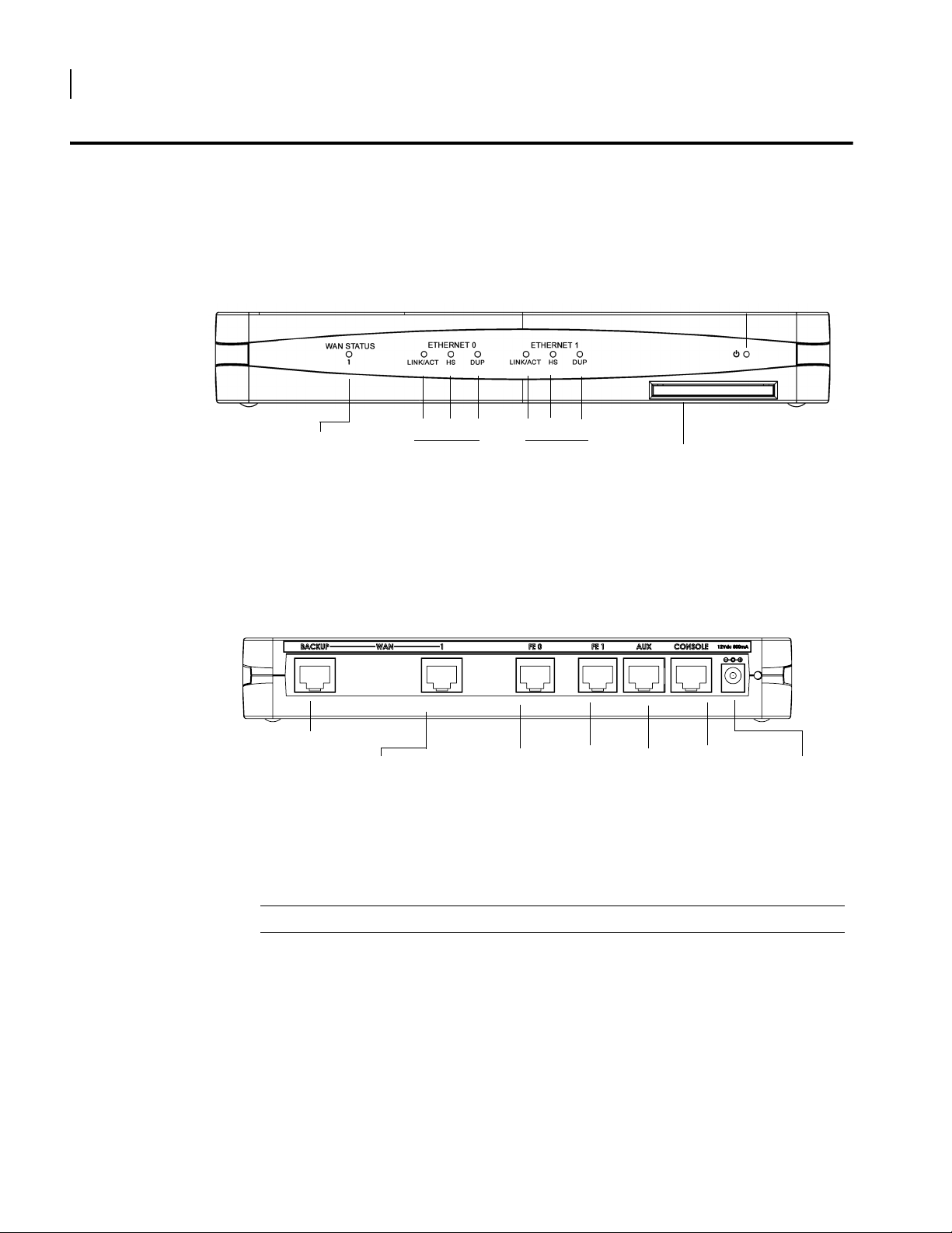
1001 Front Panel
The router front panel houses the Secure Router LEDs.
Figure 1 1001 Router Front Panel
Power LED
1001 Back Panel
WAN Port
LED
LINK/ACT HS
Ethernet 0 LEDs Ethernet 1 LEDs
DUP
LINK/ACT HS
DUP
Compact Flash
The 1001 router back panel provides connections for one WAN port, two 10/100 Base-T
Ethernet ports, one AUX port, one Console port, and a 12 VDC power input jack.
Figure 2 1001 Router Back Panel
Backup WAN Port
WAN Port
Fast Ethernet
Port 0
Fast Ethernet
Port 1
AUX Port
Console
Port
12 VDC
Input Jack
The 1001 front-panel LEDs indicate real-time unit status. Table 4 provides information about
how to interpret the LED states.
SR1001 Installation Guide
Version 8.3.5
Table 4 LED and Port Descriptions
Port Description Color
WAN STATUS 1 Indicates traffic activity
on this interface
Green = normal activity
Red = alarm state
Yellow = test mode
ETHERNET 0 / 1
LINK/ACT Indicates traffic activity
on this interface
Green = link is operational
Blinking Yellow = either receiving or sending
traffic
Red = packet collisions
HS Indicates traffic speed
on the interface
Off = 10 Mbps
Green = 100 Mbps

Table 4 LED and Port Descriptions (continued)
Port Description Color
DUP Indicates the type of
duplex mode
Power Indicates system power
status
Compact Flash Port for compact flash
Off = Half duplex
Green = Full duplex
Green = power on
Off = power off
—
module
Table 5 1001 Back-Panel Ports
Connector Description
WAN 1 WAN connection port. This port accepts cables with RJ-48C connectors.
Backup WAN An ISDN backup option is supported in releases 8.3 and higher. This option
provides a backup if the primary network connection is lost. This port
accepts cables with RJ-45 connectors.
FE 0 / 1 Ethernet LAN connection ports. These ports accept cables with RJ-45
cable connectors.
AUX Reverse telnet connection. This port accepts a cable with an RJ-45 cable
connector.
Console Console management port. This port accepts a cable with an RJ-45 cable
connector.
DC power 12 VDC power connection. This port accepts the 2 mm. power connector
on the DC power supply cable that ships with the 1002 router.
9
SR1001 Installation Guide
Version 8.3.5
1001 Serial
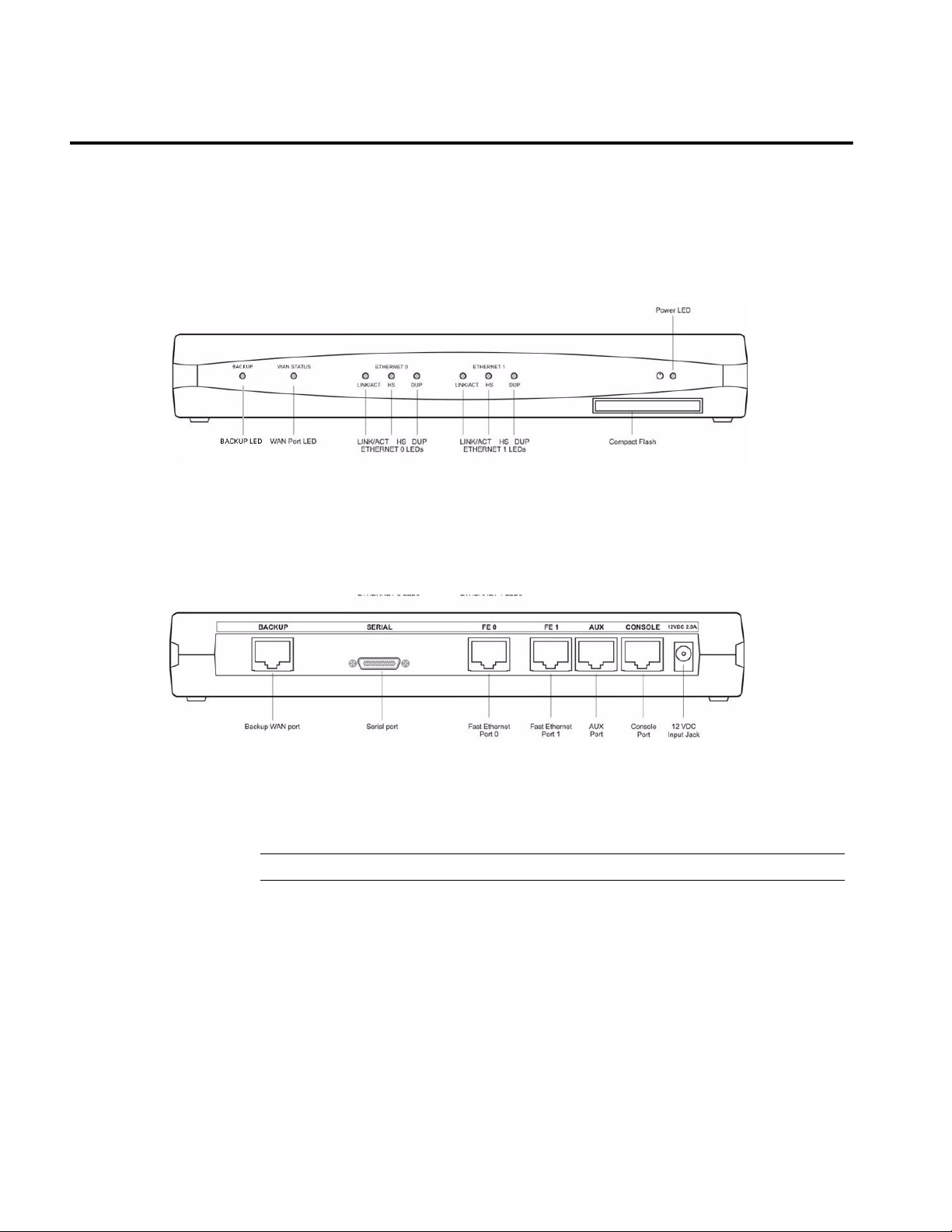
1001S Front Panel
1001S Back Panel
The router front panel houses the Secure Router LEDs.
Figure 3 1001 Router Front Panel
The 1001 router back panel provides connections for one WAN port, two 10/100 Base-T
Ethernet ports, one AUX port, one Console port, and a 12 VDC power input jack.
Figure 4 1001 Router Back Panel
The 1001 front-panel LEDs indicate real-time unit status. Table 6 provides information about
how to interpret the LED states.
Table 6 LED and Port Descriptions
Port Description Color
Backup LED Indicates traffic activity
on this interface
WAN STATUS Indicates traffic activity
on this interface
ETHERNET 0 / 1
LINK/ACT Indicates traffic activity
on this interface
HS Indicates traffic speed
on the interface
Green = normal activity
Red = alarm state
Yellow = test mode
Green = normal activity
Red = alarm state
Yellow = test mode
Green = link is operational
Blinking Yellow = either receiving or sending
traffic
Red = packet collisions
Off = 10 Mbps
Green = 100 Mbps

Table 6 LED and Port Descriptions (continued)
Port Description Color
DUP Indicates the type of
duplex mode
Power Indicates system power
status
Compact Flash Port for compact flash
Off = Half duplex
Green = Full duplex
Green = power on
Off = power off
—
module
Table 7 1001 Back-Panel Ports
Connector Description
Backup WAN An ISDN backup option is supported. This option provides a backup if the
primary network connection is lost. This port accepts cables with RJ-45
connectors.
Serial Serial WAN connection port. This port accepts cables with D-style
connectors.
FE 0 / 1 Ethernet LAN connection ports. These ports accept cables with RJ-45
cable connectors.
AUX Reverse telnet connection. This port accepts a cable with an RJ-45 cable
connector.
Console Console management port. This port accepts a cable with an RJ-45 cable
connector.
DC power 12 VDC power connection. This port accepts the 2 mm. power connector
on the DC power supply cable that ships with the 1002 router.
11
SR1001 Installation Guide
Version 8.3.5

12
CHAPTER
2
Product Introduction 1001 Serial
SR1001 Installation Guide
Version 8.3.5
Site Preparation
3
I
NSTALLATION
This chapter describes how to install and prepare the SR1001 for operation. Information is also
provided describing the Secure Router front and back panels, operator interface, how to
mount the chassis, and how to connect network and power cables.
Before you install the SR1001, familiarize yourself with the network interface and power
connections described in this chapter.
Before installing a SR1001, ensure that the site conditions comply with the following
requirements and that the mounting equipment, tools, and cables are available at the
installation site.
13
Environment
Site location is important for the proper operation of the SR1001. Place the unit in a clean, dry
environment with adequate air circulation. Allow additional clearance around the Secure
Router for foot traffic and access to cable connectors on the rear panel.
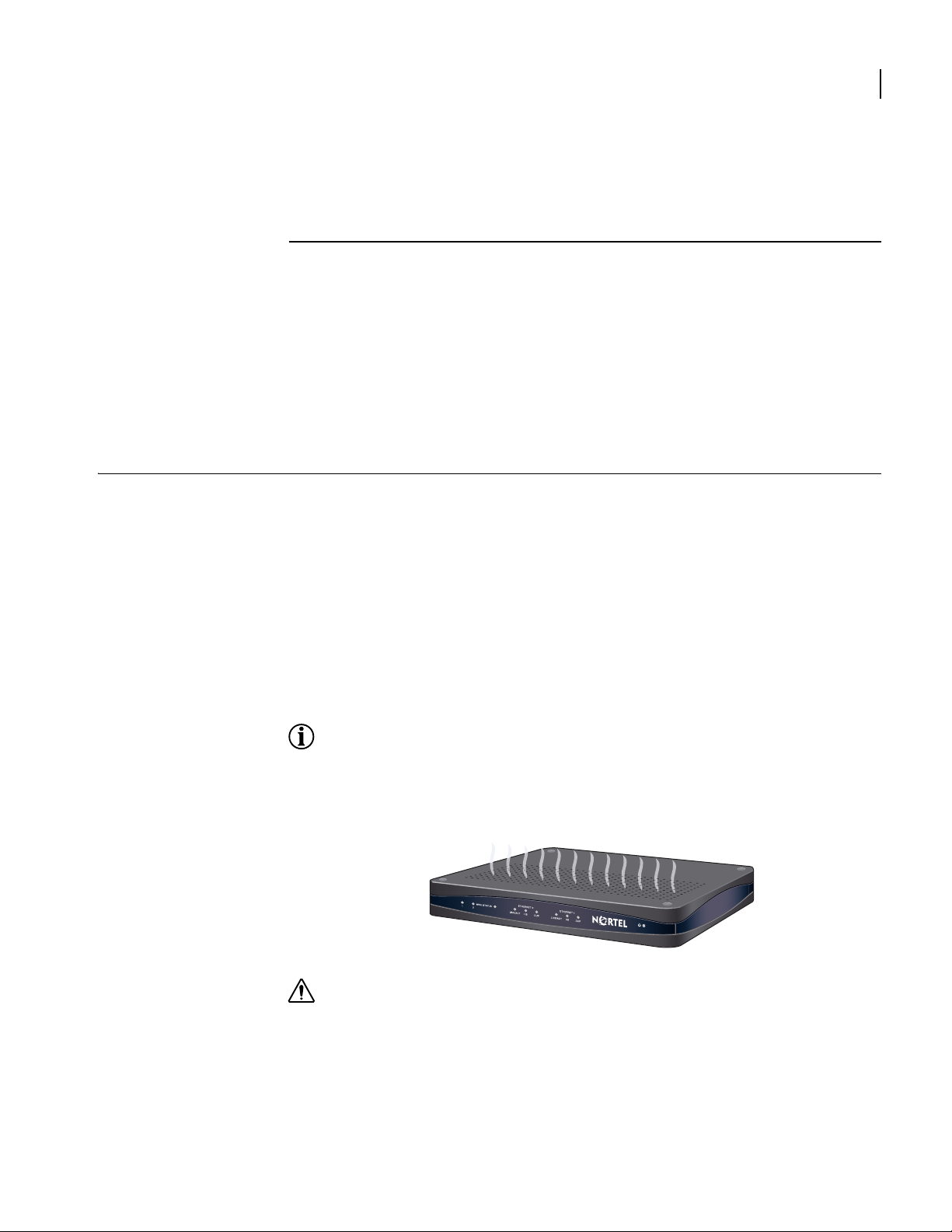
Figure 5 shows the convection cooling vents on top of the unit. To prevent an
over-temperature condition, which could result in system failure or performance degradation,
make sure that these vents are not obstructed.
NOTE: In normal operation, the router will be “warm to the touch.”
Figure 5 Chassis Air Flow
CAUTION:
of the router and such action could lead to equipment damage.
Refer to Appendix A for more information about environmental requirements.
Do not stack routers on top of each other. Doing so will defeat the convection cooling ability
SR1001 Installation Guide
Version 8.3.5
 Loading...