

Nortel SL-100 Product Manual

Communication Server 2100
Meridian SL-100 Product Guide
555-4001-103
.

Document status: Standard
Document version: 20.01
Document date: 20 October 2006
Copyright © 2006, Nortel Networks
All Rights Reserved.
The information inthis document is sourced in Canada, the United States of America, and the United Kingdom.
This is the Way, This is Nortel, Nortel, the Nortel logo, the globemark design, and the NORTEL NETWORKS
corporate logo, are trademarks of Nortel Networks. All other trademarks are the property of their respective owners.
All rights reserved.

Contents
New in this release 7
About this document 9
Meridian SL-100 hardware overview 11
SuperNode generations 13
Meridian SL-100 platforms 14
Meridian SL-100 cabinets and frames 16
References 18
Meridian SL-100 general functions 21
System functionality 21
Network modules 25
XA-Core 27
Enhanced Network (ENET) 30
Link Peripheral Processor 34
Peripheral Modules 37
3
Overview of functional elements 13
Meridian SuperNode for large applications 14
Cabinet concept 16
Dimensions 17
Core 22
Bus functions 25
Link functions 25
Meridian Cabinet Network Interface (MCNI) 32
Single-Shelf Link Peripheral Processor (SSLPP) 37
Meridian SL-100 peripherals 41
Trunk peripherals 42
Introduction 42
Digital Trunk Controller 42
Spectrum Peripheral Module (SPM) 47
Line peripherals 52
Introduction 52
Line Group Controller 54
Line Concentrating Modules 59
Communication Server 2100
Meridian SL-100 Product Guide
555-4001-103 20.01 Standard
Copyright © 2006, Nortel Networks Nortel Networks Confidential
.
SE09 20 October 2006

4 Contents
Line Trunk Controller 62
Intelligent Peripheral Equipment (IPE) 62
Link Peripheral Processor-based peripherals 70
Ethernet Interface Unit (EIU) 70
IP Client Manager for the Meridian SL-100 72
Description 72
Hardware requirements 76
Features 76
Meridian SL-100 remote units 77
Remote Switching Center (RSC) 77
Remote Switching Center family 77
MCRM-S (RSC-S) 78
Extended distance on MCRM-S 78
Emergency Stand Alone 79
Meridian Cabinet Remote Unit (MCRU) 80
Remote off Remote (MCRU off of MCRM-S) 81
Trunking off of Remote Switching Center 81
PRI trunking off the RSC-S 81
Cabinet modular hardware 83
Cabinet descriptions 83
Cabinet dimensions 83
Cabinet exterior design 85
Cabinet interior design 85
Cabinet cabling 85
Earthquake resistance 86
Site level power and grounding 86
Power plant configuration 86
System grounding and bonding 87
Communication link grounding 91
Workstation, printer, and modem power and grounding 91
Overview of cabinet modules 92
Core modules 92
Network modules 92
Peripheral modules 92
Maintenance and administration modules 93
Remote peripheral modules 93
SuperNode cabinet module 100
Cooling unit 101
System Load Module 101
Computing Module 101
Message switch 102
Power supply module 102
Frame Supervisory Panel 102
Communication Server 2100
Meridian SL-100 Product Guide
555-4001-103 20.01 Standard
Copyright © 2006, Nortel Networks Nortel Networks Confidential
.
SE09 20 October 2006

Power requirement 102
SuperNode SE cabinet 103
Single-shelf core 103
System Load Module 103
Single-shelf bus 104
Cooling unit 104
Link interface 104
Enhanced Network 104
Frame Supervisory Panel 104
Power requirement 104
SNSE cabinet 104
Network cabinets 105
Enhanced network 105
Meridian Cabinet Network Interface (MCNI) 107
Trunk cabinet modules 109
Meridian Cabinet Trunk Module-ISDN 109
Cabinetized Integrated Services Module 111
Line cabinet modules 111
Meridian cabinet line module 112
Meridian Cabinet Line Module-Enhanced 113
Intelligent Peripheral Equipment Column 115
Peripheral cabinet modules 117
Link Peripheral Processor 117
Cabinetized Multi-Vendor Interface 122
Spectrum Peripheral Module 124
Cabinetized International Peripheral Equipment 125
Meridian cabinet auxiliary module phase 3 127
Maintenance and administration cabinet modules 127
Meridian Cabinet Auxiliary Module phase 3 127
Cabinetized Integrated Services Module 129
Cabinetized Miscellaneous Spares Storage 130
Cabinetized Power Distribution Center 131
Remote peripheral cabinet modules 134
Meridian Cabinet Remote Unit 134
Meridian Cabinetized Remote Module-SONET 135
Contents 5
System configuration 137
Cabinet update 137
Single Shelf Link Peripheral Processor (SSLPP)/Fiberized Link Interface Shelf
(FLIS) 137
Hardware components 137
Software 138
System configuration overview 138
Standard group configurations 139
Communication Server 2100
Meridian SL-100 Product Guide
555-4001-103 20.01 Standard
Copyright © 2006, Nortel Networks Nortel Networks Confidential
.
SE09 20 October 2006

6 Contents
Primary group lineups 139
Secondary group lineups 143
Merged lineups or non-standard configurations 144
System performance 147
Power consumption 147
Floor loading 149
Environmental requirements 149
Standard features 149
OAMP for Meridian SL-100 networks 151
Maintenance and Administration Position 151
Overview 151
General maintenance 151
Line maintenance 154
Trunk maintenance 155
Administration subsystems 156
Access control system 157
System configuration 158
Telephones 161
Overview 161
IPE telephones 161
M3900 Series Digital Telephones 162
M3900 Series Digital Telephones accessories 167
Corporate Directory Application 170
Meridian Digital Telephones 171
Meridian Digital Telephone accessories 174
Meridian Business Sets 176
Additional analog sets 179
Meridian Services Attendant Console 179
Communication Server 2100
Meridian SL-100 Product Guide
555-4001-103 20.01 Standard
Copyright © 2006, Nortel Networks Nortel Networks Confidential
.
SE09 20 October 2006

New in this release
There have been no updates to the document in this release.
7
Communication Server 2100
Meridian SL-100 Product Guide
555-4001-103 20.01 Standard
Copyright © 2006, Nortel Networks Nortel Networks Confidential
.
SE09 20 October 2006

8 New in this release
Communication Server 2100
Meridian SL-100 Product Guide
555-4001-103 20.01 Standard
Copyright © 2006, Nortel Networks Nortel Networks Confidential
.
SE09 20 October 2006
About this document
Purpose and audience
This document describes the circuit-switched Meridian SL-100 hardware
platform, of which many of the components can be reused when evolving to
the Communication Server 2100.
This document’s audience is service provisioning, administrative and
network management and planning personnel.
How to check the version and issue of this document
The version and issue of the document are indicated by numbers (for
example, 01.01). For example, the first release of a document is 01.01. In
the next software release cycle, the first release of the same document
is 02.01.
The first two digits indicate the version. The version number increases
each time the document is updated to support a new software release. The
second two digits indicate the issue. The issue number increases each
time the document is revised, but re-released in the same software release
cycle. For example, the second release of a document in the same software
release cycle is 01.02.
9
ATTENTION
To determine whether you have the latest version of this document, check the
release information in the Communication Server 2100 Commercial Systems
Master Index of Publications (555-4031-001).
References in this document
This guide provides an overview of the hardware components that make
up the Meridian SL-100. The document is designed to act as a road map
to help you find the hardware information related to your specific network
configuration. As such, at the end of many of the sections in this guide,
there are tables that list references to more detailed information about the
component described.
Communication Server 2100
Meridian SL-100 Product Guide
555-4001-103 20.01 Standard
Copyright © 2006, Nortel Networks Nortel Networks Confidential
.
SE09 20 October 2006

10 About this document
Note: Reference documents may contain Nortel product names used in
the carrier market.
Communication Server 2100
Meridian SL-100 Product Guide
555-4001-103 20.01 Standard
Copyright © 2006, Nortel Networks Nortel Networks Confidential
.
SE09 20 October 2006

Meridian SL-100 hardware overview
This section describes the Meridian SL-100 circuit-switched hardware
components.
This chapter contains the following sections:
•
"SuperNode generations" (page 13)
•
"Meridian SL-100 platforms" (page 14)
•
"Meridian SL-100 cabinets and frames" (page 16)
•
"References" (page 18)
To provide large enterprise customers with maximum flexibility when
selecting their communication system, Nortel continues to offer the
circuit-switched Meridian SL-100 solution. The Meridian SL-100 combines
the best of both worlds: Nortel carrier-grade Digital Multiplex System
(DMS) and the world leading Meridian 1 Private Branch Exchange (PBX).
The Meridian SL-100’s architectural design which includes processing,
switching, access and call control layers, enables you to invest in new
technologies, such as IP technology, and to do so incrementally while
leveraging your investment in the rest of your Meridian SL-100 system.
11
The Meridian SL-100 provides fully integrated voice and data
communications and management. It serves as either a switching or
networking manager for corporate, military and institutional purposes. This
large-scale, software-controlled private switching system handles up to
60,000 digital voice or data connections, or a combination of both, to a wide
variety of other voice or data systems.
There are two types of Meridian SL-100 systems and they are differentiated
by the core processor. The first type is the SuperNode core with enhanced
call processing and handling capabilities. The second type is a scaled-down
version of the SuperNode core, called the SuperNode Space Enhanced
(SNSE) core, designed to serve smaller offices with a maximum of 36,000
lines.
Note: The number of lines supported depends on the switch
configuration, the feature implementation, the amount of ISDN line
penetration and the Centi-Call Seconds (CCS) per line.
Communication Server 2100
Meridian SL-100 Product Guide
555-4001-103 20.01 Standard
Copyright © 2006, Nortel Networks Nortel Networks Confidential
.
SE09 20 October 2006
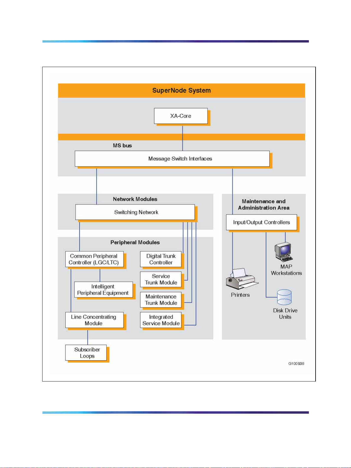
12 Meridian SL-100 hardware overview
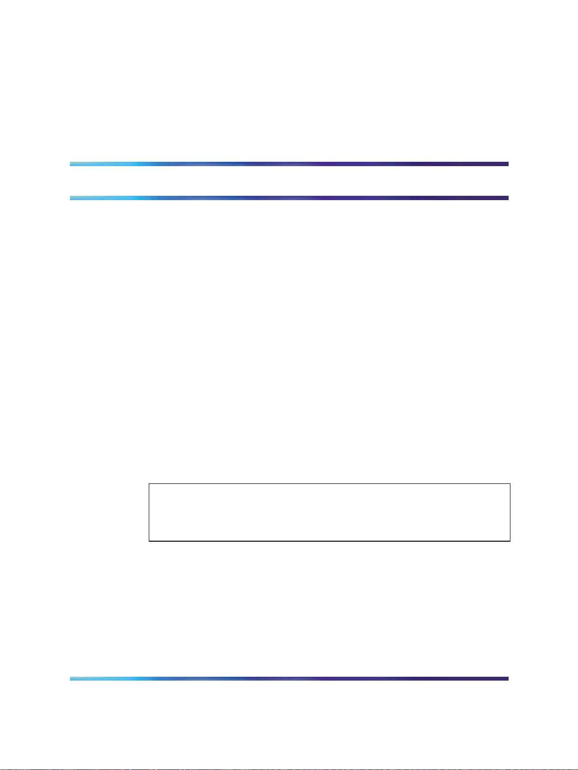
Figure 1 "Meridian SL-100 layered hardware architecture" (page 12)
illustrates the Meridian SL-100 hardware architecture.
Figure 1 Meridian SL-100 layered hardware architecture
Some of the attributes of the hardware architecture which distinguish the
Meridian SL-100 from the competition include the following:
•
built-in redundancy which sets the standard in reliability
•
small footprint and energy-efficient design to minimize facility costs
•
modular design which allows organizations to scale the system to meet
their requirements
•
clear evolutionary paths to minimize upgrade costs and maximize
investment protection, including the migration to the Communication
Server 2100 which is the next generation of the Meridian SL-100
Communication Server 2100
Meridian SL-100 Product Guide
555-4001-103 20.01 Standard
Copyright © 2006, Nortel Networks Nortel Networks Confidential
.
SE09 20 October 2006
SuperNode generations
The SuperNode generation of switches, which includes the SuperNode and
SuperNode SE systems, is based on evolutionary technology, yielding the
following improvements over the NT40 generation of switches:
• increased processing and call-handling capability
•
reduced size
•
improved reliability
SuperNode switches consists of the following three components:
•
core - the control component.
•
bus - the messaging component; hereafter called the Message Switch
(MS) bus or MS bus in this document to differentiate it from other types
of buses.
•
link - the software infrastructure that implements public networking
standards including Common Channel Signaling and ISDN public
standards and protocols.
SuperNode generations 13
SuperNode switches have a distributed architecture and increased
processing capabilities, which provide an infrastructure for the development
of new features and services. The SuperNode system also provides an
interface to fiber transmission systems.
Overview of functional elements
All Meridian SL-100 systems consist of the same functional elements: the
control component, the messaging component, the switching network,
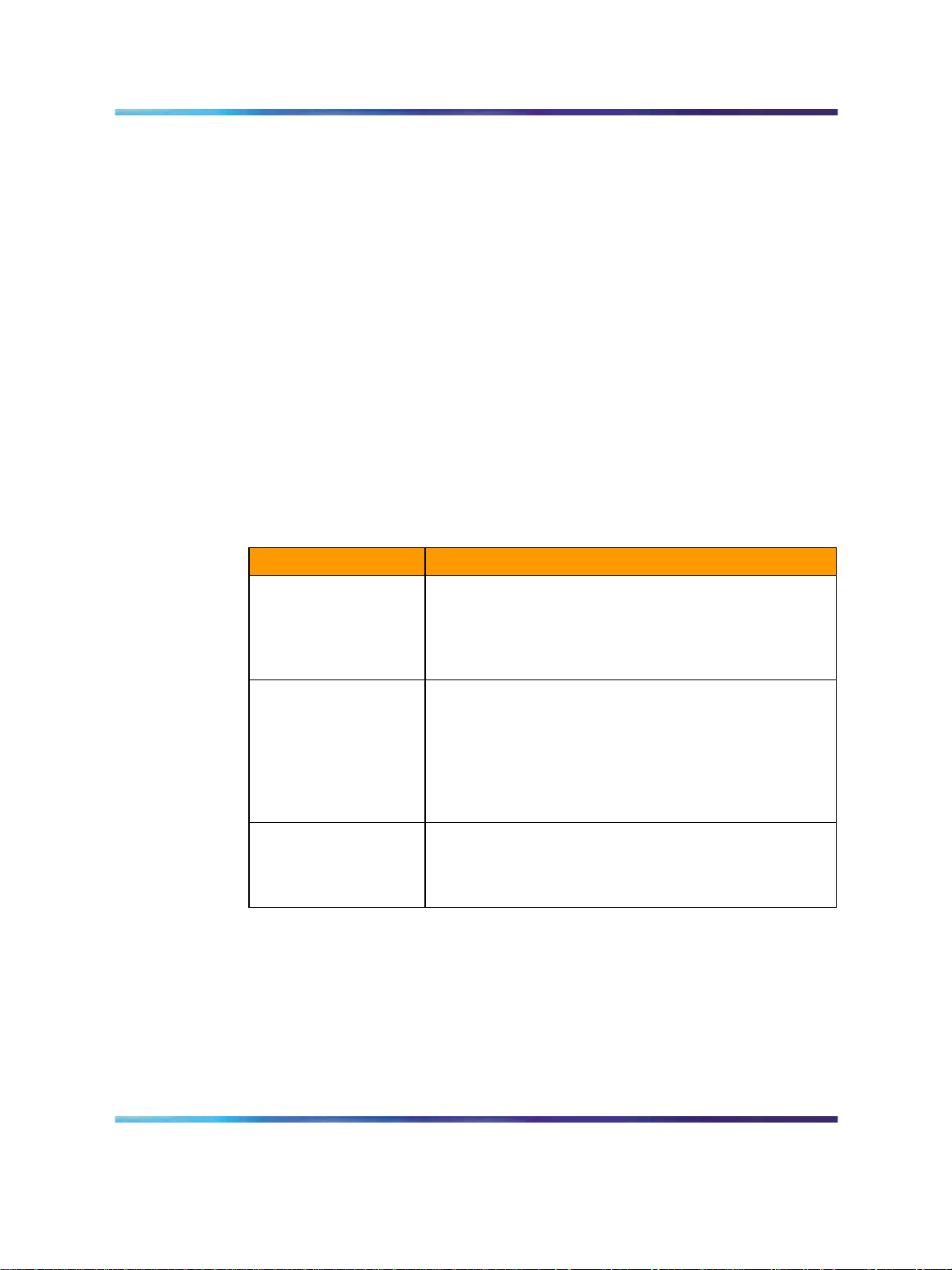
the peripheral modules and the input/output controller. Table 1 "Meridian
SL-100 functional elements" (page 13) describes the functional elements.
Table 1 Meridian SL-100 functional elements
Element Description
Control component The duplicated control component coordinates call processing, including
the actions of the switching network and of the Peripheral Modules. The
SuperNode control component is called the "core." The core’s major
elements are a Computing Module (CM) and System Load Module (SLM).
Note: The SuperNode messaging component is not contained in the
control component, but is separate and called the message switch bus.
Messaging
component
The messaging component routes messages within the Meridian SL-100
system. The SuperNode messaging component is the MS bus. The MS
bus consists of duplicated message switches. The message switch is
based on the SuperNode CPU; thus, it uses some of the same software
as the Computing Module and the Central Control Complex CPU.
Communication Server 2100
Meridian SL-100 Product Guide
555-4001-103 20.01 Standard
Copyright © 2006, Nortel Networks Nortel Networks Confidential
.
SE09 20 October 2006

14 Meridian SL-100 hardware overview
Element Description
Switching network The switching network is a digital switching matrix that interconnects
the Peripheral Modules using Time Division Multiplexing (TDM). The
switching network has duplicate network planes for reliability. It is made
up of microprocessor-controlled digital switching Network Modules (NM)
and is connected to the SuperNode MS bus.
Peripheral Modules The Peripheral Modules (PMs) provide an interface between the switching
network and telephony terminals such as lines and trunks. They also
provide an interface between the Meridian SL-100 system and Remote
Digital Terminals (RDTs), access nodes and other vendors’ switching
equipment.
Input/Output
Controller
The Input/Output Controller (IOC) provides an interface between the
messaging component (the SuperNode MS bus) and input/output devices
such as magnetic tape drives, disk drives, data links, video display
units and printers. A video display unit connected to the IOC is used
as a component of a Maintenance and Administration Position (MAP)
workstation. The MAP workstation provides a user interface to the
Meridian SL-100 system.
Meridian SL-100 platforms
Meridian SuperNode for large applications
The Meridian SL-100 is a powerful communications system that combines
advanced hardware architecture with premier PBX software features. The
Meridian SL-100 is based on the highly successful technology Nortel
developed for Digital Multiplex System (DMS) central office switches.
These switches have set worldwide standards for reliability. The built-in
redundancy of all critical system components ensures system operations
integrity. As the largest member of the Meridian 1 family of sophisticated
business communications systems, the Meridian SL-100 has provided
superior service in a variety of industries for almost two decades.
The Meridian SL-100 supports a wide range of voice, data, video and
multimedia applications. The system can be flexibly configured to address
both current and future capacity and applications requirements as a result of
its 100,000digital voice or data line capacity threshold. The Meridian SL-100
incorporates the Nortel advanced Dual Plane Common Control (DPCC)
design, which efficiently uses the system’s processing power by providing
distributed control over many processors. The system’s modular design
also allows easy upgrades as new processor technology becomes available.
Figure 2 "Meridian SuperNode" (page 15) shows an example of a Meridian
SuperNode.
Communication Server 2100
Meridian SL-100 Product Guide
555-4001-103 20.01 Standard
Copyright © 2006, Nortel Networks Nortel Networks Confidential
.
SE09 20 October 2006
Meridian SL-100 platforms 15
Figure 2 Meridian SuperNode
Meridian SuperNode SE (Space Enhanced) for smaller
applications
As a smaller alternate solution to the Meridian SuperNode, the SuperNode
SE (SNSE) is specifically designed for lower line-size (4,000 to 50,000)
application-intensive requirements. The specific number of provisionable
lines is dependent on the actual switch configuration, Centi-Call Seconds
(CCS) per line and the actual mix of feature penetration.
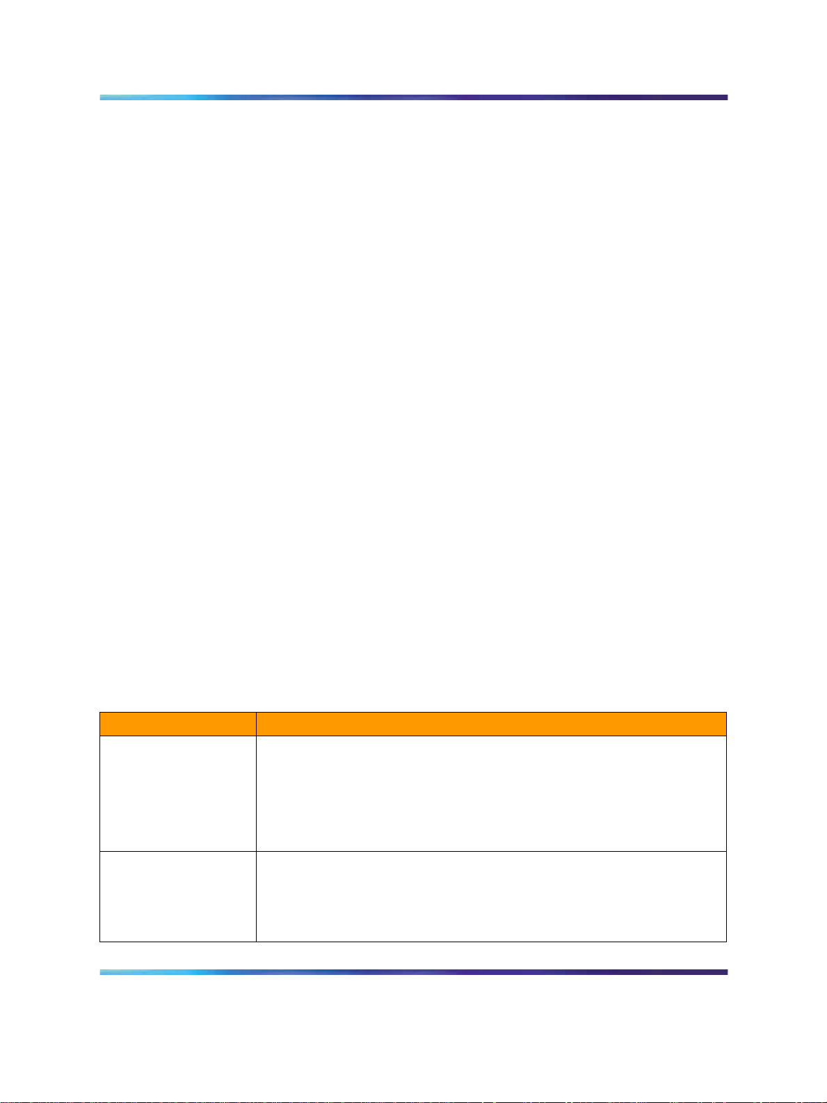
The SNSE configuration provides the platform for current and future
Meridian SL-100 applications and features required for the small switch
market (see Figure 3 "Meridian SuperNode SE" (page 15)).
Figure 3 Meridian SuperNode SE
Communication Server 2100
Meridian SL-100 Product Guide
555-4001-103 20.01 Standard
Copyright © 2006, Nortel Networks Nortel Networks Confidential
.
SE09 20 October 2006

16 Meridian SL-100 hardware overview
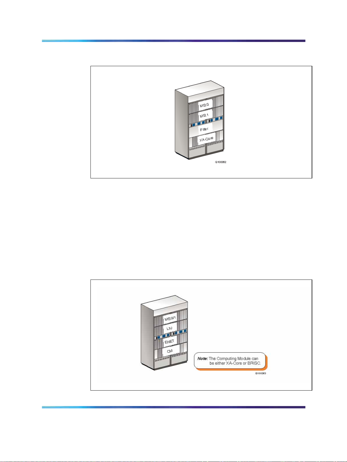
The Meridian SuperNode SE offering combines the functionality of the
DMS-Core, DMS-Bus, 16K Enhanced Network (ENET) and a single-shelf
Link Peripheral Processor (LPP) into one cabinet by providing the following:
•
State-of-the-art processing capability of XA-Core.
•
Duplex ENET configured for up to 16,000 channels on one shelf.
•
A Link Interface Shelf (LIS) for additional 12 Interface Units (IUs)
depending on provisioning rules.
•
Available with optimal memory using block sparing.
• Duplicated, load-sharing Message Switch (DMS-Bus) on one shelf.
Meridian SL-100 cabinets and frames
Cabinet concept
The Meridian SL-100 system cabinet structure consists of basic hardware
switching modules mounted in 1.8 m (6 ft.) gray or brown cabinets.
Modular design
Modular design techniques are used in the developmentof both the software
and hardware. Modularity can be thought of as the implementation of a
complex system through a set of functional units or modules connected by
well-defined interfaces. As a result of proper module and interface design,
the various units can be connected, disconnected, modified or improved
without affecting either the operation of the other modules in the system
or the system as a whole.
This modularity gives the system flexibility in physical layout and function,
in providing special features and in system expansion. The cabinetized
Meridian SL-100 can be adapted to specific customer line, trunk and service
circuit requirements through additional engineering.
Advantages of the cabinet
The cabinetized Meridian SL-100 offers these benefits:
•
Provides pre-cabled, factory-assembled, and tested cabinets; thus,
reducing on-site installation or commissioning intervals.
•
Provides a modular system that easily expands and accommodates
variations in system size and feature choices and allows integration
of future system enhancements.
•
Eliminates the need for additional external earthquake bracing by using
prebraced steel cabinets.
•
Presents a modern, computer-style appearance, ideally suited for
computer rooms having raised flooring and low, suspended ceilings.
• Shortens delivery time.
Communication Server 2100
Meridian SL-100 Product Guide
555-4001-103 20.01 Standard
Copyright © 2006, Nortel Networks Nortel Networks Confidential
.
SE09 20 October 2006
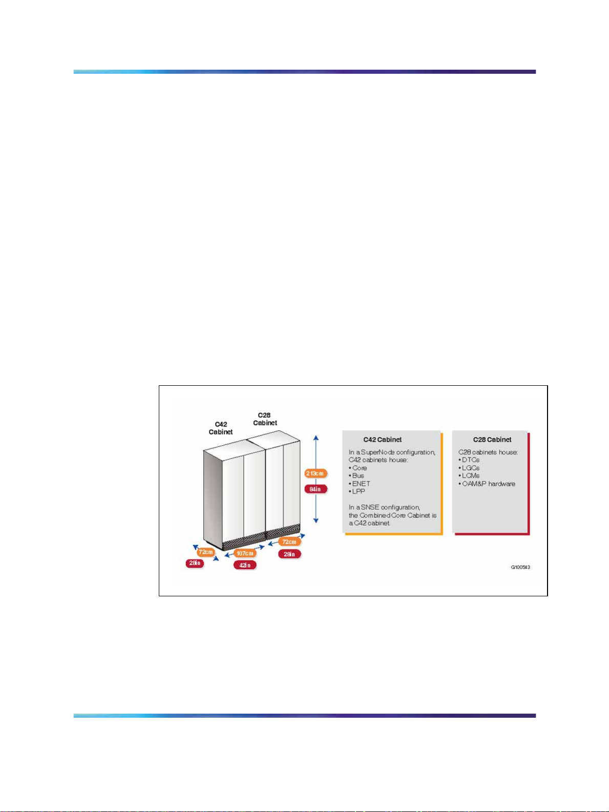
•
Dimensions
Current Meridian SL-100 hardware is housed in cabinets or frames with the
following dimensions:
•
•
• Open frame: 213 cm high 72 cm wide 46 cm deep (84" 28 18")
Each cabinet or frame contains four shelves with slots for equipment (for
example, card slots for inserting circuit cards). Cabinets are equipped with
double doors on both the front and rear to provide convenient access for
maintenance personnel.
Figure 4 "Dimensions of current Meridian SL-100 cabinets" (page 17)
illustrates the dimensions of C42 and C28 cabinets and lists the hardware
units that can be housed in each one. An open frame can house the same
type of units as C28 cabinets.
Meridian SL-100 cabinets and frames 17
Simplifies system expansions.
C42 cabinet: 183 cm high 107 cm wide 72 cm deep (72" 42" 28")
C28 cabinet: 183 cm high 72 CM wide 72 cm deep (72" 27" 28")
Figure 4 Dimensions of current Meridian SL-100 cabinets
Note: Standard Meridian SL-100 frames are also used to house
the Spectrum Peripheral Module. The dimensions of the Spectrum
Peripheral Module hardware are smaller than those of equivalent
Extended Peripheral Module (XPM) units, but to minimize costs adapter
brackets are used to house Spectrum Peripheral Modules in existing
frames. Overall footprint can still be reduced, because access to all
cards in the Spectrum Peripheral Module double-height shelves is from
Communication Server 2100
Meridian SL-100 Product Guide
555-4001-103 20.01 Standard
Copyright © 2006, Nortel Networks Nortel Networks Confidential
.
SE09 20 October 2006
18 Meridian SL-100 hardware overview
the front of the frame, which means that parallel rows of Spectrum
Peripheral Module frames can be arranged back to back.
References
Table 2 "References" (page 18) shows where you can find more detailed
information about the Meridian SL-100 hardware platform and components.
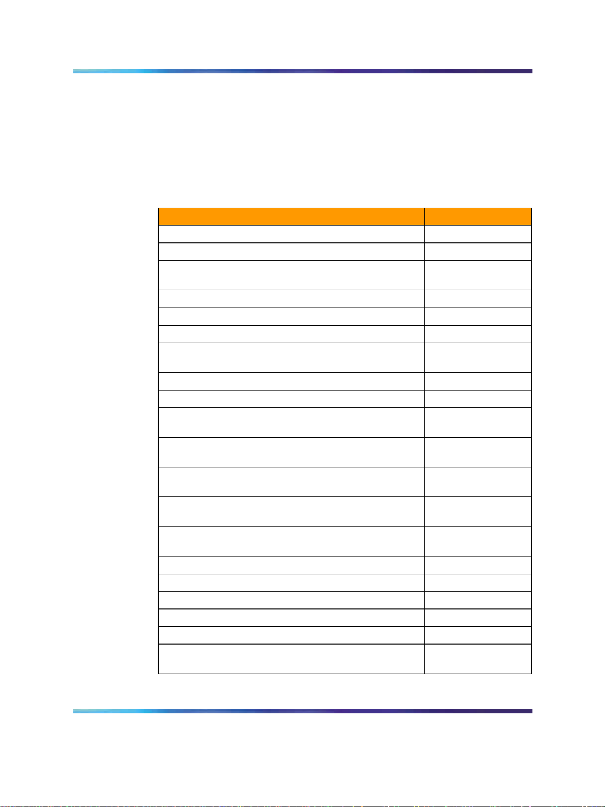
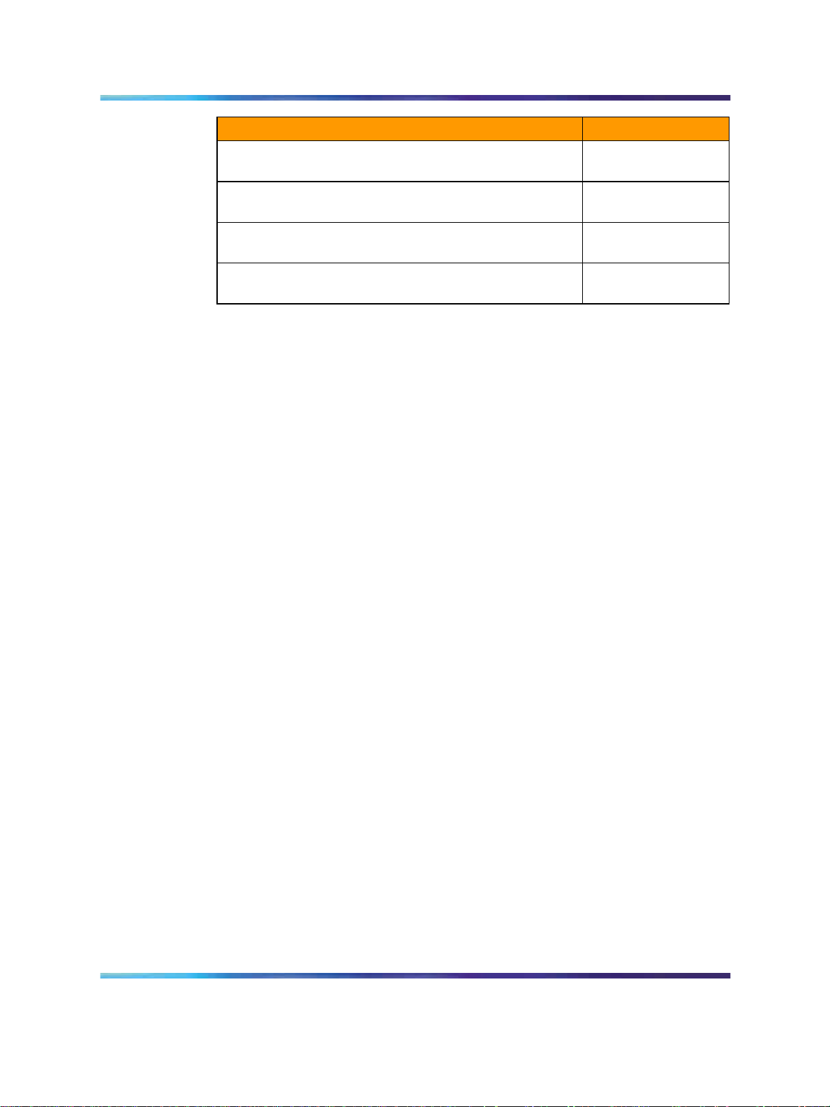
Table 2 References
Document Number
Enhanced MAP Workstation Product Guide
Ethernet Interface Unit on LPP Services Guide
Communications Server 2100 Interworking Services
Guide
Digital Line Module (DLM) Reference Manual
Remote Peripherals General Description
ISDN Primary Rate Interface Reference Manual
Communication Server 2100 ASCII SMDR Data Access
Description and Implementation
Computer-to-PBX Interface General Description
Asynchronous Interface Line Unit Reference Manual
Intelligent Peripheral Equipment (IPE) Reference
Manual
Communication Server 2100 Line Side T-1 Interface for
IPE (LTI) Services Guide
Communication Server 2100 Peripheral Module Release
Document RELDOC
Communication Server 2100 Getting Started with
Optivity Telephony Manager User Guide
555-4001-012
555-4001-024
555-4001-026
555-4001-101
555-4001-104
555-4001-106
555-4001-119
555-4001-125
555-4001-126
555-4001-129
555-4001-022
555-4001-599
555-4001-316
Communication Server 2100 Commercial Systems
555-4031-350
Translations Guide
Alarm Clearing Procedures
Trouble Locating and Clearing Procedures
Recovery Procedures
Routine Maintenance Procedures
Card Replacement Procedures
Communication Server 2100 Commercial Systems
555-4031-543
555-4031-544
555-4031-545
555-4031-546
555-4031-547
555-4031-808
Service Order Reference Manual
Communication Server 2100
Meridian SL-100 Product Guide
555-4001-103 20.01 Standard
Copyright © 2006, Nortel Networks Nortel Networks Confidential
.
SE09 20 October 2006
References 19
Document Number
Communication Server 2100 Commercial Systems
555-4031-814
Operational Measurements Reference Manual
Communication Server 2100 Commercial Systems Log
555-4031-840
Report Reference Manual
Communication Server 2100 Commercial Systems Data
555-4031-851
Schema Reference Manual
Communication Server 2100 Commercial Systems
555-4031-855
Office Parameters Reference Manual
In addition, because the Meridian SL-100is based on the DMS system, there
are many useful DMS documents that are included on the fully-searchable
Customer Documentation CD-ROM that ships with the system.
Communication Server 2100
Meridian SL-100 Product Guide
555-4001-103 20.01 Standard
Copyright © 2006, Nortel Networks Nortel Networks Confidential
.
SE09 20 October 2006

20 Meridian SL-100 hardware overview
Communication Server 2100
Meridian SL-100 Product Guide
555-4001-103 20.01 Standard
Copyright © 2006, Nortel Networks Nortel Networks Confidential
.
SE09 20 October 2006

Meridian SL-100 general functions
The Meridian SL-100 system consists of the following functional areas:
•
SuperNode and SuperNode SE system functionality
•
Network Modules
•
Peripheral Modules
•
maintenance and administration area
The main functional areas of the Meridian SL-100 system are connected by
links carrying speech samples and control messages in the form of serial
digital data. Each link provides a two-way (four-wire) transmission path for
32 channels of Time Division Multiplexed (TDM) data.
The speech links have 30 channels for transmission of Pulse Code
Modulation (PCM) speech samples and two channels for control messages.
The message links have all 32 channels assigned exclusively to control
messages.
21
This chapter contains the following sections:
• "System functionality" (page 21)
•
"Network modules" (page 25)
•
"XA-Core" (page 27)
•
"Enhanced Network (ENET)" (page 30)
•
"Link Peripheral Processor" (page 34)
•
"Peripheral Modules" (page 37)
System functionality
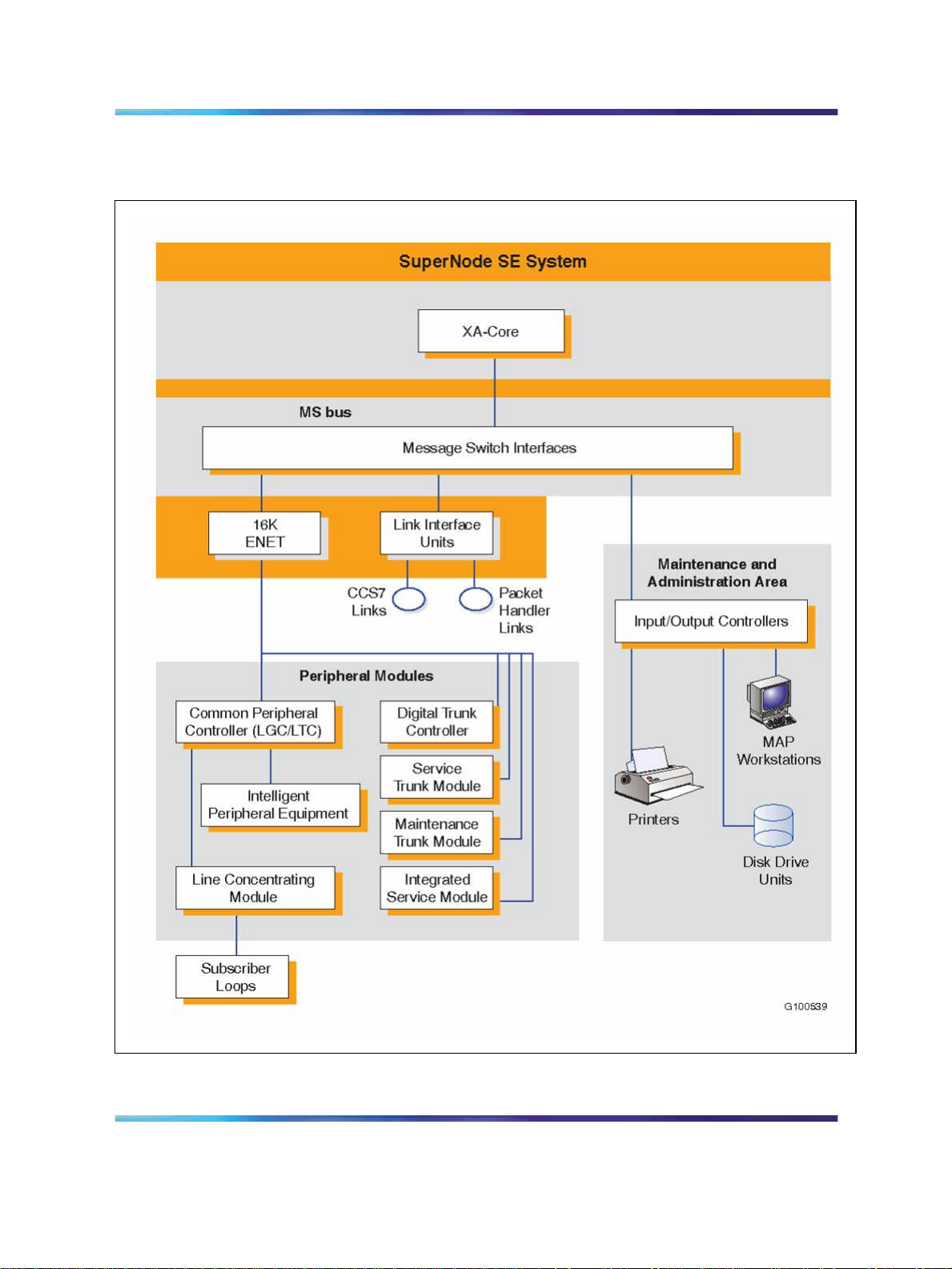
Both the full-sized SuperNode and the SuperNode SE systems consist of
two hardware elements (core and bus) and one software element (link), as
illustrated in Figure 5 "Functional areas of the Meridian SuperNode system
(one of duplicated planes)" (page 23) and Figure 6 "Functional areas of the
Meridian SuperNode SE system with internal 16K ENET and optional LIUs
(one o" (page 24), and described in the following paragraphs.
Communication Server 2100
Meridian SL-100 Product Guide
555-4001-103 20.01 Standard
Copyright © 2006, Nortel Networks Nortel Networks Confidential
.
SE09 20 October 2006

22 Meridian SL-100 general functions
Core
There are two Meridian SL-100 core processors currently in the field as
follows:
•
XA-Core see "XA-Core" (page 27).
•
Series 70 (BRISC)
Note: BRISC is still supported on existing systems, but is no longer
shipped with new systems.
Series 70 Core functions
The SuperNode and SuperNode SE components are duplicated for
reliability and operate as synchronized pairs. One plane is in-service
(active) and performs call processing and other operations. The other plane
(standby) performs the same operations, but checks for variations between
itself and the active plane. Any difference between the two planes results in
a maintenance interruption and a recovery action.
Each plane of the BRISC core consists of the following:
•
Computing Module (CM)
•
system memory
•
System Load Module (SLM)
•
call management processor
•
Message Switch (MS) interfaces
The core performs the call processing function, system management,
system sanity checking, maintenance, and loading and downloading of
programs. The core interacts with other components of the Meridian SL-100
through the MS bus, which supports multiple application modules.
Communication Server 2100
Meridian SL-100 Product Guide
555-4001-103 20.01 Standard
Copyright © 2006, Nortel Networks Nortel Networks Confidential
.
SE09 20 October 2006
System functionality 23
Figure 5 Functional areas of the Meridian SuperNode system (one of duplicated planes)
Communication Server 2100
Meridian SL-100 Product Guide
555-4001-103 20.01 Standard
Copyright © 2006, Nortel Networks Nortel Networks Confidential
.
SE09 20 October 2006
24 Meridian SL-100 general functions
Figure 6 Functional areas of the Meridian SuperNode SE system with internal 16K ENET and optional LIUs (one of duplicated planes)
Communication Server 2100
Meridian SL-100 Product Guide
555-4001-103 20.01 Standard
Copyright © 2006, Nortel Networks Nortel Networks Confidential
.
SE09 20 October 2006

Bus functions
The MS bus supplies system messaging, allowing system peripherals and
processors connected to the MS bus ports to communicate freely with one
another.
The MS bus consists of the following:
•
processor bus
•
transaction bus
•
control processor with supporting memory
•
mapper
•
processor transaction bus interface
•
system clock
•
port interface units
Link functions
The link is the software and protocol structure used on signaling links
for SuperNode and SuperNode SE applications that interface with the
telecommunications network. The link enables the networking of SuperNode
systems, SuperNode SE systems and interfaces for customer programming
applications. The link delivers a range of network signaling services based
on public standards.
Network modules 25
Protocol sets within the link include the Common Channel Signaling #7
(CCS7) set for the following:
•
transaction and trunk signaling
•
Integrated Services Digital Network (ISDN) access
•
network operations protocols
•
X.25 packet communications
The link also supports the DMS packet handler, which provides national
ISDN-1 compliant packet service. DMS packet handler signaling includes
the following:
•
X.25 and X.75/X.75’ protocols for packet processing
•
ISDN Basic Rate Interface (BRI) access
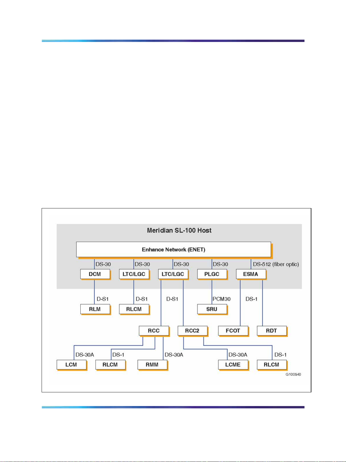
Network modules
The Network Module (NM) is one of the main functional components of the
Meridian SL-100 that connects to the MS bus. Figure 7 "Functional areas of
the Meridian SL-100 network module (ENET)" (page 26) is an illustration
of the NM using the Enhanced Network (ENET).
Communication Server 2100
Meridian SL-100 Product Guide
555-4001-103 20.01 Standard
Copyright © 2006, Nortel Networks Nortel Networks Confidential
.
SE09 20 October 2006
26 Meridian SL-100 general functions
The NMs are duplicated as two parallel sets (plane 0 and plane 1) of the
two-way transmission paths for each connected channel between the
Peripheral Modules (PMs). The duplicated parallel paths ensure that if one
channel in a transmission path fails, the alternate channel is immediately
available. Meanwhile, recovery action is taken to restore the failed channel.
Two types of networks are supported: Junctored Network (JNET) and
Enhanced Network, although Nortel recommends the upgrade to ENET for
improved performance. ENET is a non-blocking, junctorless, single-stage
time switch that is compatible with all Meridian SL-100 PMs. ENET is a
replacement for JNET, therefore, the two networks cannot coexist in the
same system. ENET hardware is either housed in an external ENET cabinet
(for SuperNode systems) or a single ENET shelf located in the SuperNode
SE cabinet. ENET is provisioned with new SuperNode systems and all
SuperNode SE systems.
Note: JNET’s last supported release will be SE07 and it will not be
supported after December 31, 2005.
Figure 7 Functional areas of the Meridian SL-100 network module (ENET)
Communication Server 2100
Meridian SL-100 Product Guide
555-4001-103 20.01 Standard
Copyright © 2006, Nortel Networks Nortel Networks Confidential
.
SE09 20 October 2006
XA-Core
XA-Core 27
XA-Core is an architecture for achieving scalable computing power.
XA-Core represents a fundamental paradigm shift in providing incremental
capacity. With XA-Core, capacity growth is a function of both the speed of
each processor and the number of processors. XA-Core is based on the
PowerPC family of processors which provides the system with a powerful
Central Processing Unit (CPU).
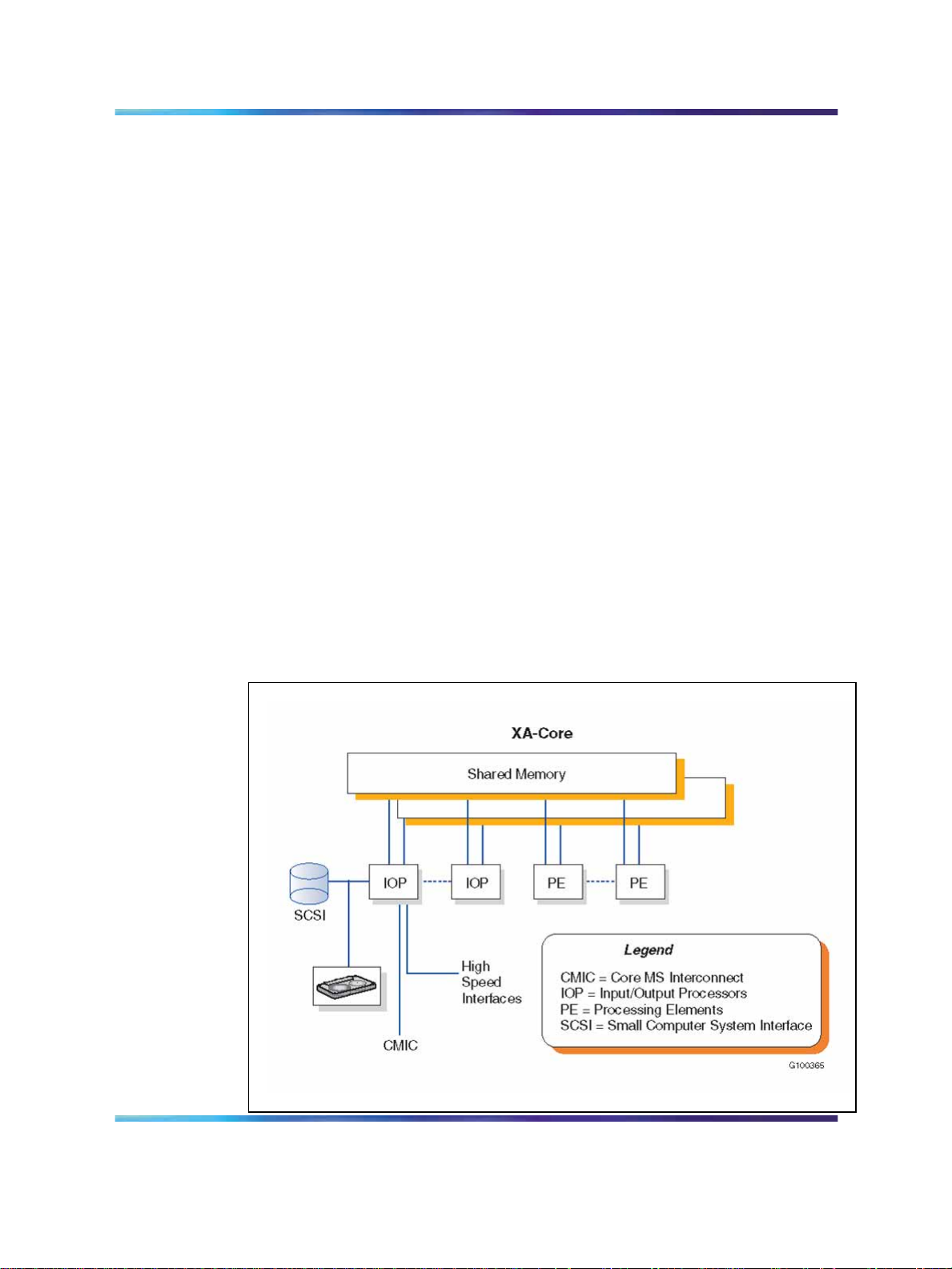
XA-Core’s processing capability offers significant improvements in switching
capacity through a multiprocessor architecture using the following three
elements:
•
Shared Memory (SM)
• Multiple Processing Elements (PEs)
•
I/O Processors (IOPs)
The DMS-bus processes and sends messages to nodes in the SuperNode
and SuperNode SE switches. The DMS-bus has two load-sharing Message
Switches (MS). The DMS-link allows the Meridian SL-100 core and
DMS-bus to communicate in the SuperNode and SuperNode SE switches.
The base core software establishes the signaling, which is then executed by
the XPMs to the PSTN. The DMS-link is the connection path between the
XA-Core and the rest of the system. Figure 8 "XA-Core architecture" (page
27) illustrates the XA-Core architecture.
Figure 8 XA-Core architecture
Communication Server 2100
Meridian SL-100 Product Guide
555-4001-103 20.01 Standard
Copyright © 2006, Nortel Networks Nortel Networks Confidential
.
SE09 20 October 2006
28 Meridian SL-100 general functions
From a strategic perspective, XA-Core provides a key element in
transitioning to the next-generation Communication Server 2100 in
Nortel’s multiservice, packet-switched IP telephony solution. All XA-Core
components used in current TDM (circuit-switched) applications can be
retained in the Communication Server 2100, which preserves network
investments and simplifies transition.
XA-Core replaces the existing CM/SLM as the DMS-Core in both the
SuperNode and SuperNode SE (SNSE) configurations of the central core.
The XA-Core processing power and architecture allow switch capacity to
both increase substantially and to be scalable to meet future requirements.
Processing elements, memory, and I/O devices can be added or provisioned
as needed.
Note: Installation of XA-Core requires the Enhanced Network (ENET).
XA-Core is comprised of a single shelf consisting of three cards as shown in
Table 3 "XA-Core card configuration" (page 28).
Table 3
XA-Core card configuration
Card
Processor Element
(PE)
Input/Output
Processors
Shared Memory (SM) Shared Data Store, Master Copy of Program Store.
Description
Power MPC7410/500 MHz.
Duplicated per PE for fault detection.
512 MB onboard memory for Program Store.
Scalable Real-time - in-service addition of PEs.
Scalable Reliability - "n+m" reliability.
Common Host I/O Processors (IOP).
Individual personality "Packlets" - two per IOP.
OC-3/ATM MS Links.
Remote Terminal Interfaces (RS-232).
Provisionable mass storage devices: >= 4 GB disks;
1.3-4 GB DAT.
Fault Tolerant File System.
Duplex memory; independently mated 32 MB blocks.
Hot spare for reliability.
192 MB granularity; 1728 MB capacity.
XA-Core features include the following:
•
scalable capacity based on multiprocessing
•
plug-in processors, memory and I/O port cards
•
provides 2.3 times the capacity of SN70EM
— three active processors, including hot spare
— 768 MB of memory
Communication Server 2100
Meridian SL-100 Product Guide
555-4001-103 20.01 Standard
Copyright © 2006, Nortel Networks Nortel Networks Confidential
.
SE09 20 October 2006

XA-Core 29
•
robust reliability through
— fault detection and recovery
— built-in self-test and diagnostics
— auto identify, auto-configure and auto-test
•
capability for 10 times capacity of SN70EM
•
Shared-Memory
•
Parallel-Processing Machine
•
Independent scalable subsystems
The benefits of the XA-Core architecture include the following:
•
Reduced cost of ownership.
• Scalable capacity.
•
Software compatibility with both cross-threaded and non-cross-threaded
call processing architectures.
•
Hardware compatibility with Series I, Series II and Series III peripherals.
•
Order of magnitude improvement in core reliability, exceeding GR-512
requirements.
•
Compatibility with the full line of DMS-100 family products and all
existing software architectures.
•
Simplified "plug-and-play" provisioning of processor elements,
input/output processors and memory, allow this processor to enable
the large enterprise to make incremental capacity adjustments easily
and cost-effectively.
•
The life-cycle of XA-Core components is significantly extended over the
current single processor architecture. Instead of completing an upgrade
by replacement of the entire processor set, new XA-Core components
can be simply added along side existing investments.
•
With the XA-Core, spare processors can be used to share the
call-processing load, as well as for "hot" backup. Instead of remaining
in standby mode, these spares actively participate in the switch’s
processing to broaden reliability and supplement capacity during
short-term overload situations.
•
Auto provisioning of processor elements, enhanced fault detection and
isolation, simpler extraction of failed cards and LED activity indicators
are some of XA-Core’s enhancements to Operations, Administration,
Maintenance and Provisioning (OAMP). These enhancements can
contribute to significant savings in technician time spent on maintenance
activities.
Communication Server 2100
Meridian SL-100 Product Guide
555-4001-103 20.01 Standard
Copyright © 2006, Nortel Networks Nortel Networks Confidential
.
SE09 20 October 2006
30 Meridian SL-100 general functions
•
Versatility - XA-Core can serve as a platform to boost capacity for
organizations hosting large line sizes of feature-rich services such as
Advanced Intelligent Network and National ISDN-2.
•
DMS SuperNode system compatibility - Interfaces with components
developed for the DMS SuperNode and DMS SuperNode SE systems,
such as the Message Switch (MS), Enhanced Network (ENET) and
Link Peripheral Processor (LPP).
•
Abundant processing capacity - XA-Core can help make real-time
concerns a thing of the past. In addition, dynamic call processing
distribution and a 2-Gigabyte addressable memory range expand call
processing capacity and speed, and favorably enhance life cycle costs.
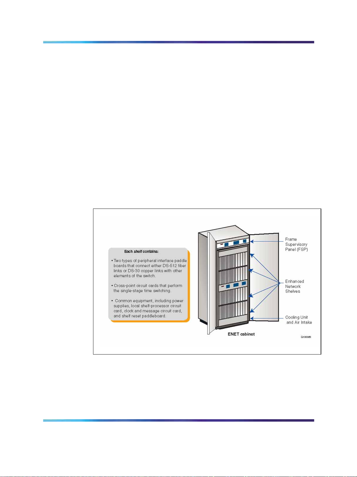
Enhanced Network (ENET)
ENET is the switching platform for the Meridian SL-100. It is a key hardware
element which supports a full range of wideband services. Figure 9 "ENET
cabinet" (page 30) shows an ENET cabinet.
Figure 9 ENET cabinet
The Enhanced Network replaces the junctored network modules. It is a
non-blocking, junctorless, single-stage time switch that can expand its
capacity from 4k to 128k unidirectional channels. ENET is compatible with
all Meridian SL-100 PMs, including the fiberized Series II PMs.
Communication Server 2100
Meridian SL-100 Product Guide
555-4001-103 20.01 Standard
Copyright © 2006, Nortel Networks Nortel Networks Confidential
.
SE09 20 October 2006
 Loading...