

Page 1

Nortel Secure Router 4134
Quick Start
NN47263-100 (323245-A)
Page 2

Document status: Standard
Document version: 01.01
Document date: 16 July 2007
Copyright © 2007, Nortel Networks
All Rights Reserved.
The information in this document is subject to change without notice. The statements, configurations, technical
data, and recommendations in this document are believed to be accurate and reliable, but are presented without
express or implied warranty. Users must take full responsibility for their applications of any products specified in this
document. The information in this document is proprietary to Nortel Networks.
The software described in this document is furnished under a license agreement and may be used only in accordance
with the terms of that license. The software license agreement is included in this document.
Trademarks
*Nortel, the Nortel logo, and the Globemark are trademarks of Nortel Networks.
All other trademarks are the property of their respective owners.
Restricted rights legend
Use, duplication, or disclosure by the United States Government is subject to restrictions as set forth in subparagraph
(c)(1)(ii) of the Rights in Technical Data and Computer Software clause at DFARS 252.227-7013.
Notwithstanding any other license agreement that may pertain to, or accompany the delivery of, this computer
software, the rights of the United States Government regarding its use, reproduction, and disclosure are as set forth
in the Commercial Computer Software-Restricted Rights clause at FAR 52.227-19.
Statement of conditions
In the interest of improving internal design, operational function, and/or reliability, Nortel Networks reserves the right
to make changes to the products described in this document without notice.
Nortel Networks does not assume any liability that may occur due to the use or application of the product(s) or
circuit layout(s) described herein.
Portions of the code in this software product may be Copyright © 1988, Regents of the University of California. All
rights reserved. Redistribution and use in source and binary forms of such portions are permitted, provided that the
above copyright notice and this paragraph are duplicated in all such forms and that any documentation, advertising
materials, and other materials related to such distribution and use acknowledge that such portions of the software
were developed by the University of California, Berkeley. The name of the University may not be used to endorse or
promote products derived from such portions of the software without specific prior written permission.
SUCH PORTIONS OF THE SOFTWARE ARE PROVIDED "AS IS" AND WITHOUT ANY EXPRESS OR IMPLIED
WARRANTIES, INCLUDING, WITHOUT LIMITATION, THE IMPLIED WARRANTIES OF MERCHANTABILITY AND
FITNESS FOR A PARTICULAR PURPOSE.
In addition, the program and information contained herein are licensed only pursuant to a license agreement that
contains restrictions on use and disclosure (that may incorporate by reference certain limitations and notices
imposed by third parties).
International Regulatory Statements of Conformity
This is to certify that the Nortel Secure Router 4134 equipment was evaluated to the international regulatory
standards for electromagnetic compliance (EMC) and safety and were found to have met the requirements for the
following international standards:
•
EMC – Electromagnetic Emissions – CISPR 22, Class A
•
EMC – Electromagnetic Immunity – CISPR 24
•
Electrical Safety – IEC 60950, with CB member national deviations
Page 3

Further, the equipment has been certified as compliant with the national standards as detailed below.
National Electromagnetic Compliance (EMC) Statements of
Compliance
FCC statement (USA only)
This equipment has been tested and found to comply with the limits for a Class A digital device, pursuant to Part
15 of the Federal Communications Commission (FCC) rules. These limits are designed to provide reasonable
protection against harmful interference when the equipment is operated in a commercial environment. This
equipment generates, uses, and can radiate radio frequency energy. If it is not installed and used in accordance with
the instruction manual, it may cause harmful interference to radio communications. Operation of this equipment
in a residential area is likely to cause harmful interference, in which case users will be required to take whatever
measures may be necessary to correct the interference at their own expense.
TIA-968-A
This equipment complies with Part 68 of the FCC rules. The FCC Part 68 label is located on the bottom chassis
panel. This label contains the FCC Registration Number and Ringer Equivalence Number (REN) for this equipment.
If requested, this information must be provided to your telephone company.
Connection to the telephone network should be made by using standard modular telephone jacks, type RJ-48C. The
RJ-48C plug and/or jacks used must comply with the FCC Part 68 rules.
MFRs Port
Identifier
Facilities
Interface
Code
Service Order
Code
Network
Connectors
T1: lines 1–16 04DU9-1SN
04DU9-1ZN
6.0N RJ-48C
ICES statement (Canada only)
Canadian Department of Communications Radio Interference Regulations
This digital apparatus (Nortel Secure Router 4134) does not exceed the Class A limits for radio-noise emissions from
digital apparatus as set out in the Radio Interference Regulations of the Canadian Department of Communications.
Règlement sur le brouillage radioélectrique du ministère des Communications
Cet appareil numérique (le commutateur Nortel Secure Router 4134) respecte les limites de bruits radioélectriques
visant les appareils numériques de classe A prescrites dans le Règlement sur le brouillage radioélectrique du
ministère des Communications du Canada.
CE marking statement (Europe only)
EN 55022 statements
This is to certifythat the Nortel Secure Router 4134 equipment is shielded against the generation of radio interference
in accordance with the application of Council Directive 89/336/EEC. Conformity is declared by the application of
EN 55022 Class A (CISPR 22).
CAUTION
This device is a Class A product. In a domestic environment, this device can cause radio
interference, in which case the user may be required to take appropriate measures. For
translations of this message, see "Translations of safety messages" (page 57).
EN 55024 statement
This is to certify that the Nortel Secure Router 4134 is shielded against the susceptibility to radio interference in
accordance with the application of Council Directive 89/336/EEC. Conformity is declared by the application of
EN 55024 (CISPR 24).
Page 4
EN 300386 statement
The Nortel Secure Router 4134 complies with the requirements of EN 300386 V1.3.1 for emissions and for immunity
for a Class A device intended for use in either Telecommunicationscentre or locations other than telecommunications
centres given the performance criteria as specified by the manufacturer.
European Union and European Free Trade Association (EFTA) notice
All products labeled with the CE marking comply with R&TTE Directive (1995/5/EEC) which
includes the Electromagnetic Compliance (EMC) Directive (89/336/EEC) and the Low
Voltage Directive (73/336/EEC) issued by the Commission of the European Community.
Compliance with these directives implies conformity to the following European Norms (ENs). The equivalent
international standards are listed in parenthesis.
•
EN 55022 (CISPR 22)–Electromagnetic Interference
•
EN 55024 (IEC 61000-4-2, -3, -4, -5, -6, -8, -11)–Electromagnetic Immunity
• EN 61000-3-2 (IEC 610000-3-2)–Power Line Harmonics
• EN 61000-3-3 (IEC 610000-3-3)–Power Line Flicker
VCCI statement (Japan/Nippon only)
This is a Class A product based on the standard of the Voluntary Control Council for Interference (VCCI) for
information technology equipment. If this equipment is used in a domestic environment, radio disturbance may arise.
When such trouble occurs, the user may be required to take corrective actions.
BSMI statement (Taiwan only)
This is a Class A product based on the standard of the Bureau of Standards, Metrology and Inspection (BSMI) CNS
13438 and CNS14336 , Class A.
MIC notice (Republic of Korea only)
This device has been approved for use in Business applications only per the Class A requirements of the Republic of
Korea Ministry of Information and Communications (MIC). This device may not be sold for use in a non-business
application.
Observe the Regulatory Marking label on the back or bottom of each switch for specific certification information
pertaining to this model. Each Nortel Secure Router 4134 model is approved for shipment to/usage in Korea and is
labeled as such, with all appropriate text and the appropriate MIC reference number.
National Safety Statements of Compliance
EN 60950 statement
This is to certify that the NortelSecure Router 4134 equipment is in compliance with the requirements of EN 60950 in
accordance with the Low Voltage Directive. Additional national differences for all European Union countries have
been evaluated for compliance.
Page 5

NOM statement (Mexico only)
The following information is provided on the devices described in this document in compliance with the safety
requirements of the Norma Oficial Méxicana (NOM):
Exporter: Nortel Networks,
5400 Hellyer Ave,
San Jose, CA 95138 USA.
Importer: Nortel Networks de México, S.A. de C.V.
Avenida Insurgentes Sur #1605
Piso 30, Oficina
Col. San Jose Insurgentes
Deleg-Benito Juarez México D.F. 03900
Tel:
Fax:
52 5 480 2100
52 5 480 2199
Input: Nortel Secure Router 4134:
•
PS-SR4K-660W-AC-POE
100-240V ~ 10A/5A 50/60 Hz
•
PS-SR4K-250W-AC
100-240V ~ 5A/3A 50/60 Hz
•
PS-SR4K-250W-DC
43-72V 9.5A MAX
Información NOM (unicamente para México)
La información siguiente se proporciona en el dispositivo o en los dispositivos descritos en este documento, en
cumplimiento con los requisitos de la Norma Oficial Méxicana (NOM):
Exportador: Nortel Networks,
5400 Hellyer Ave,
San Jose, CA 95138 USA.
Importador: Nortel Networks de México, S.A. de C.V.
Avenida Insurgentes Sur #1605
Piso 30, Oficina
Col. San Jose Insurgentes
Deleg-Benito Juarez México D.F. 03900
Tel:
Fax:
52 5 480 2100
52 5 480 2199
Embarcar a: Nortel Secure Router 4134:
• PS-SR4K-660W-AC-POE
100-240V ~ 10A/5A 50/60 Hz
• PS-SR4K-250W-AC
100-240V ~ 5A/3A 50/60 Hz
•
PS-SR4K-250W-DC
43-72V 9.5A MAX
Page 6

Denan statement (Japan/Nippon only)
National Environmental Statements of Compliance
The WEEE Directive 2002/96/EC and RoHS (Restriction of Hazardous Substances) Directive 2002/95/EC sets
collection, recycling and recovery targets for various categories of electrical products and their waste.
Restriction on Hazardous Substances Directive Compliance
Statement
The Restriction on Hazardous Substances Directive (RoHS) (2002/95/EC), which accompanies the WEEE Directive,
bans the use of heavy metals and brominated flame-retardants in the manufacture of electrical and electronic
equipment. Specifically, restricted materials under the RoHS Directive are Lead (including solder used in PCB’s),
Cadmium, Mercury, Hexavalent Chromium, and Bromine.
Nortel declares compliance with the European Union (EU) RoHS Directive (2002/95/EC).
WEEE Directive Compliance Statement
This product at end of life is subject to separate collection and
treatment in the EU Member States, Norway, and Switzerland and
therefore is marked with the symbol shown at the left. Treatment
applied at end of life of these products in these countries shall comply
with the applicable national laws implementing Directive 2002/96/EC
on Waste of Electrical and Electronic Equipment (WEEE).
Nortel declares compliance with the European Union (EU) WEEE
Directive (2002/96/EC).
How to get help
This section explains how to get help for Nortel products and services.
Getting help from the Nortel web site
The best way to get technical support for Nortel products is from the Nortel TechnicalSupport web site:
www.nortel.com
This site provides quick access to software, documentation, bulletins, and tools to address issues with Nortel
products. More specifically, the site enables you to:
•
download software, documentation, and product bulletins
•
search the Technical Support web site and the Nortel Knowledge Base for answers to technical issues
•
sign up for automatic notification of new software and documentation for Nortel equipment
• open and manage technical support cases
Page 7
Getting help through a Nortel distributor or reseller
If you purchased a service contract for your Nortel product from a distributor or authorized reseller, contact the
technical support staff for that distributor or reseller.
Getting help over the phone from a Nortel Solutions Center
If you do not find the information you require on the Nortel Technical Support web site, and have a Nortel support
contract, you can also get help over the phone from a Nortel Solutions Center.
In North America, call 1-800-4NORTEL (1-800-466-7835).
Outside North America, go to the following web site to obtain the phone number for your region:
www.nortel.com/callus
Getting help from a specialist by using an Express Routing Code
An Express Routing Code (ERC) is available for many Nortel products and services. When you use an ERC,
your call is routed to a technical support person who specializes in supporting that product or service. To locate
the ERC for your product or service, go to:
w
ww.nortel.com/erc
Safety messages
This section describes the precautionary notices you find in this document. This section also contains precautionary
notices that you must read for safe operation of the Nortel Secure Router 4134.
Notices
Notice paragraphs alert you about issues that require your attention. The following paragraphs describe the types of
notices used in this guide. For translations of safety messages, see "Translations of safety messages" (page 57).
ATTENTION
An attention notice provides important information regarding the installation and operation of Nortel
products.
CAUTION
ESD
ESD notices provide information about how to avoid discharge of static electricity and
subsequent damage to Nortel products.
CAUTION
Caution notices provide information about how to avoid possible service disruption
or damage to Nortel products.
CAUTION
Vorsicht
Vorsicht Nachrichten liefern Informationen über, wie man mögliche
Service-Unterbrechung vermeidet oder Beschädigung der Nortel Produkte.
Page 8
WARNING
Warning notices provide information about how to avoid personal injury when working
with Nortel products.
WARNING
Warnung
Warnende Nachrichten liefern Informationen über, wie man Personenschäden beim
Arbeiten vermeidet mit Nortel Produkten.
DANGER
Danger—High Voltage notices provide information about how to avoid a situation or
condition that can cause serious personal injury or death from high voltage or electric
shock.
DANGER
Gefahr
Gefahr-Hochspannung nachrichten liefern Informationen über, wie man a vermeidet
Situation, die ernste Verletzung oder Tod vom elektrischen Schlag verursachen kann.
DANGER
Danger notices provide information about how to avoid a situation or condition that can
cause serious personal injury or death.
DANGER
Gefahr
Gefahrnachrichten liefern Informationen über, wie man eine Situation oder eine
Bedingung vermeidet, die kann Ursache ernste Personenschäden oder Tod.
Cautions and warnings for the Secure Router 4134
The following precautionary messages apply to the Secure Router 4134. For your safety, read these precautions
carefully before proceeding with installation of the product.
WARNING
Only qualified service personnel must perform installation. Read and follow all warning
notices and instructions marked on the product or included in the documentation. For
translations of this statement, see "Translations of safety messages" (page 57).
Page 9
WARNING
This product relies on the building’s installation for overcurrent protection. Ensure that a
fuse or circuit breaker no larger than 120 V AC, 15 A U.S. (240 V AC, 10 A international)
is used on the phase conductors. For translations of this statement, see "Translations
of safety messages" (page 57).
CAUTION
To reduce the risk of fire, use only number 26 AWG or larger UL Listed or CSA Certified
Telecommunication Line Cord for all network connections.
CAUTION
Vorsicht
Verringern Sie die Gefahr des Feuers. Benutzen Sie nur Nr. 26AWG-Lehreoder größere
UL registriertes oder CSA zugelassenes NachrichtentechnikNetzanschlußschnur für
alle Network Connections.
CAUTION
Risk of explosion if battery is replaced by an incorrect type. Dispose of used batteries
according to the instructions.
CAUTION
Vorsicht
Gefahr der Explosion, wenn Batterie nach einer falschen Art ersetzt wird. Entledigen
Sie sich benutzte Batterien entsprechend den Anweisungen.
Hardware Notice
The Lithium battery in this product is part of a non-volatile memory device and will retain data for 10 years in the
absence of power. Nortel does not consider the lithium battery in this unit a field replaceable or serviceablepart and
should not be accessed by the customer.
DANGER
Risk of injury by electric shock
Before working on this equipment, be aware of proper safety practices and the hazards
involved with electrical circuits. Use only power cords that have a grounding path.
Ensure the switch is properly grounded before powering on the unit.
WARNING
Risk of eye injury by laser
Fiber optic equipment can emit laser or infrared light that can injure your eyes. Never
look into an optical fiber or connector port. Always assume that fiber optic cables are
connected to a light source.
Page 10
WARNING
Warnung
Glasfaserausrüstung kann Laser oder Infrarotlicht ausstrahlen, die Ihre Augen verletzen
können. Nie schauen Sie in ein aus optischen Fasern oder Steckertor. Nehmen Sie
immer an, daß Glasfaserkabel sind angeschlossen an eine Lichtquelle.
CAUTION
If you do not install interface modules in slots, be sure to keep the metal cover plates
in place over the slots. Removing the cover plates impedes airflow and proper cooling
of the unit. For translations of this statement, see "Translations of safety messages"
(page 57).
Personal safety and equipment protection
Read this section to prevent injury and equipment damage.
Module protection
The following practices prevent equipment damage when you work on the Nortel Secure Router 4134:
•
Always wear a grounded antistatic wrist strap when you handle modules.
•
Always set modules on appropriate antistatic material.
•
Handle modules by the faceplate and handles. Do not touch pins or electrical connections.
•
Do not leave interface module or power supply module slots empty. You must fill all slots with modules or slot
covers to maintain safety compliance, proper cooling, and electromagnetic interference (EMI) containment
in the shelf.
• Ensure that your environment meets the requirements for temperature, humidity, and cleanliness. See
"Environmental requirements" (page 55).
•
Do not overtighten thumb screws or lug nuts. Tighten screws and nuts until they are snug, plus a quarter turn. If
you use a power tool to tighten screws, use a low torque setting of 2 to 3 in–lb (0.226 to 0.339 N-m).
Cables and connectors protection
The following practices prevent damage to cables and connectors:
• Support cables to prevent any stress on the connectors. If you have a high-density cable configuration, use an
appropriate cable management system to relieve stress on the cables. Also ensure that cables are threaded
neatly and that you employ cable ties as required.
•
Do not exceed the bend radius recommended for the type of cable installed.
•
Fiber-optic cables and connectors require special care:
— Cover connectors with rubber safety plugs when they are not connected.
— Before you install or replace fiber-optic cables, clean the connectors.
— Do not exceed the bend radius that is recommended for fiber-optic cable. The acceptable bend radius for
fiber-optic cable is ten times its diameter, or 2.5 to 5 cm (1 to 2 in.). If you use a radius of less than the
recommended bend radius, a loss of signal integrity can result. Loss of signal integrity caused by incorrect
bend radius is difficult to diagnose.
Page 11

Electrostatic discharge
Electrostatic discharge (ESD) is the transfer of charge between objects at different electrical potentials. ESD can
change the electrical characteristics of a semiconductor device, and degrade or destroy it. ESD can cause equipment
to malfunction or fail.
To dissipate or neutralize electrostatic charges, use proper grounding and use conductive or dissipative materials.
Use a grounded ESD wrist strap. When you use a wrist strap, any charge in your body can go to ground rather
than damage a hardware module.
If you must ship the product, ensure you use proper antistatic packaging to shield the product from charge caused by
movement of the product within the shipping container.
Antistatic material
Antistatic material prevents electrical damage to equipment, and therefore prevents the interruption of normal
operations in an electronic system.
Place modules on an appropriate antistatic material when you replace hardware.
Use an ESD pad or antistatic packaging.
ATTENTION
Some antistatic packaging is effective only on the inside of the package.
Page 12

Page 13

13
Contents
New in this release 15
Features 15
Secure Router 4134 chassis 15
Optional interface modules 15
AC and DC power supplies 16
Introduction 17
Navigation 17
Secure Router 4134 installation and initial configuration 19
Secure Router 4134 installation and initial configuration tasks 19
Secure Router 4134 installation and initial configuration navigation 20
Installing the Secure Router 4134 chassis and hardware
components 23
Unpacking and inspecting the Secure Router 4134 chassis 23
Installing a power supply module 24
Prerequisites 25
Installing the mounting brackets on the chassis 25
Prerequisites 27
Installing the chassis 28
Prerequisites 28
Grounding the chassis 29
Prerequisites 30
Installing the interface modules 32
Prerequisites 33
Installing a Small Module 34
Installing a Medium Module 34
Installing a Large Module 35
Installing or removing an internal VPN/IPSec module 36
Installing the internal VPN/IPSec module 36
Prerequisites 36
Removing the internal VPN/IPSec module 38
Prerequisites 39
Connecting power cables 40
Nortel Secure Router 4134
Quick Start
NN47263-100 01.01 Standard
10.0 16 July 2007
Copyright © 2007, Nortel Networks
.
Page 14

14 Contents
Connecting AC power cables 41
Connecting DC power 42
Powering up the router 46
Prerequisites 46
Verifying a successful installation 46
Configuring the Secure Router 4134 for remote access 49
Connecting a terminal for local access 49
Prerequisites 49
Establishing remote access 50
Using SSH for remote access 51
Changing the default administrator password 52
Environmental requirements 55
Translations of safety messages 57
Class A device caution statement 57
Qualified service personnel warning statement 58
Overcurrent warning statement 59
Cover plate warning statement 60
Power cord warning statement 61
Nortel Secure Router 4134
Quick Start
NN47263-100 01.01 Standard
10.0 16 July 2007
Copyright © 2007, Nortel Networks
.
Page 15

15
New in this release
The following section details what’s new in the Nortel Secure Router 4134
— Quick Start (NN47263-100) for Release 10.0.
Features
See the following sections for information about feature changes:
•
"Secure Router 4134 chassis" (page 15)
•
"Optional interface modules" (page 15)
•
"AC and DC power supplies" (page 16)
Secure Router 4134 chassis
The Nortel Secure Router 4134 is a secure Wide Area Network (WAN)
routing platform designed for use as customer premises equipment (CPE).
The Secure Router 4134 provides multiservice capabilities for carrier- and
self-managed enterprise customers. The Secure Router 4134 is modular,
which allows you to add a variety of Local Area Network (LAN), WAN,
and Metropolitan Area Network (MAN) port connections in the form of
interchangeable network modules. The Secure Router 4134 is also capable
of both Layer 2 and Layer 3 switching.
The Secure Router 4134 chassis is two rack units high (3.5 inches; 8.9
centimeters). You mount the Secure Router 4134 in a 19-in. (48.26 cm)
equipment rack. For information about how to install the chassis, see
"Installing the Secure Router 4134 chassis and hardware components"
(page 23).
Optional interface modules
The Secure Router 4134 has horizontal slots for small, medium, and large
interface modules. The chassis has four small slots and three medium slots.
You can adapt two of the medium slots to accommodate a large module
(which spans two medium slots). For information about how to install
interface modules, see "Installing the interface modules" (page 32).
Nortel Secure Router 4134
Quick Start
NN47263-100 01.01 Standard
10.0 16 July 2007
Copyright © 2007, Nortel Networks
.
Page 16

16 New in this release
AC and DC power supplies
The Secure Router 4134 has two slots for power supply modules. You
can install single or dual power supply modules in any of the following
configurations:
•
one or two standard AC input modules
•
one or two Power over Ethernet (PoE) AC input modules
•
one standard AC and one PoE input module
•
one or two DC input modules
• one (standard or PoE) AC and one DC input module
Power supplies are available in the following wattage:
•
250 Watt (W) AC
•
660 W AC (410 W available for PoE)
•
250 W DC
The Secure Router 4134 ships with the power supply module or modules
installed that you ordered with the chassis. You can order power supply
modules separately and install them in the field. For information about
installing power supply modules, see "Installing a power supply module"
(page 24).
Nortel Secure Router 4134
Quick Start
NN47263-100 01.01 Standard
10.0 16 July 2007
Copyright © 2007, Nortel Networks
.
Page 17

17
Introduction
Nortel Secure Router 4134 — Quick Start (NN47263-100) provides basic
instruction on how to install the hardware and perform initial configuration of
the Nortel Secure Router 4134. The Quick Start is intended for experienced
installers.
Navigation
•
"Installing the Secure Router 4134 chassis and hardware components"
(page 23)
•
"Configuring the Secure Router 4134 for remote access" (page 49)
•
"Translations of safety messages" (page 57)
Nortel Secure Router 4134
Quick Start
NN47263-100 01.01 Standard
10.0 16 July 2007
Copyright © 2007, Nortel Networks
.
Page 18

18 Introduction
Nortel Secure Router 4134
Quick Start
NN47263-100 01.01 Standard
10.0 16 July 2007
Copyright © 2007, Nortel Networks
.
Page 19

19
Secure Router 4134 installation and
initial configuration
Install the Secure Router 4134 and log on to prepare the unit for
configuration and deployment in your network.
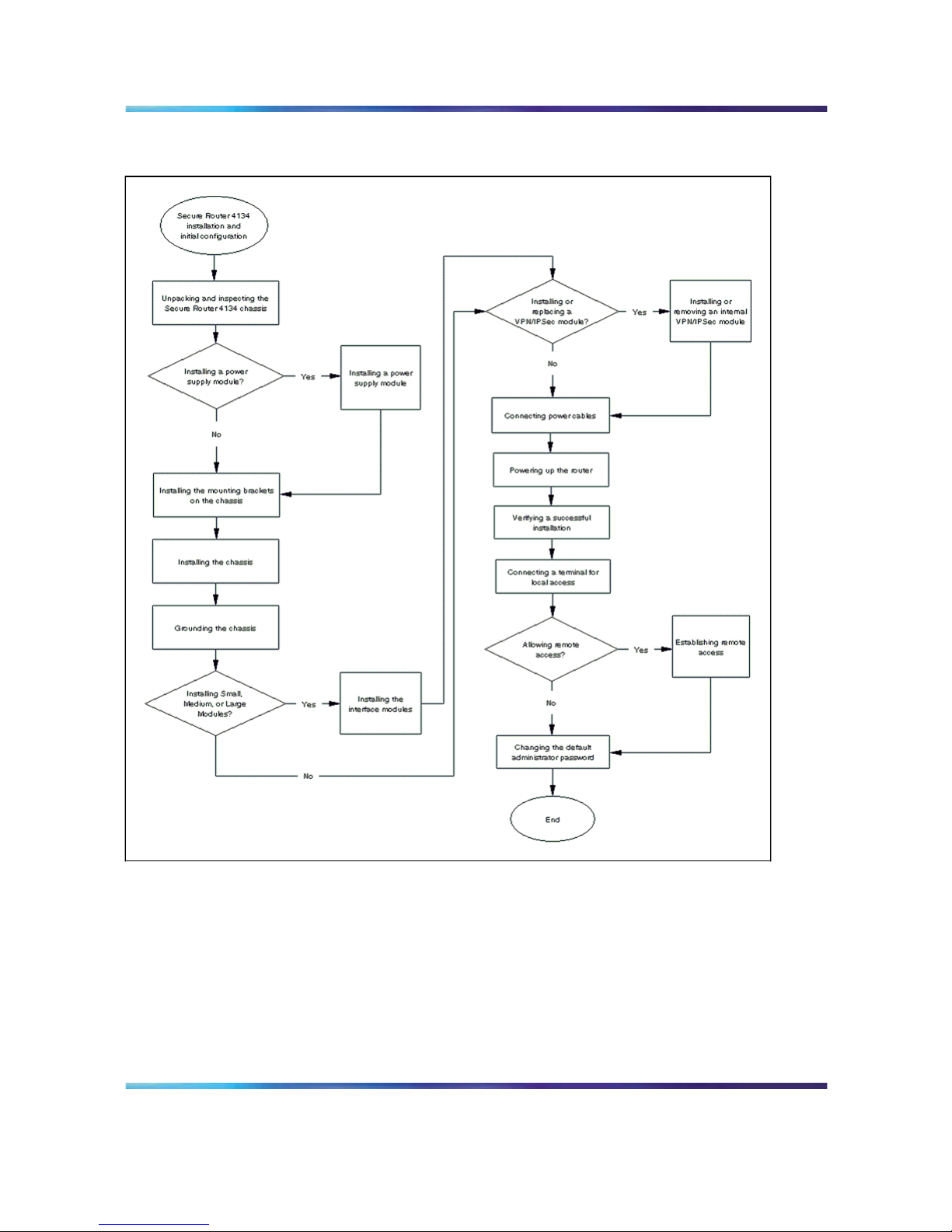
Secure Router 4134 installation and initial configuration tasks
This work flow shows you the sequence of tasks you perform to install the
Secure Router 4134 and prepare the unit for system configuration. To link
to any task, go to "Secure Router 4134 installation and initial configuration
navigation" (page 20).
Nortel Secure Router 4134
Quick Start
NN47263-100 01.01 Standard
10.0 16 July 2007
Copyright © 2007, Nortel Networks
.
Page 20
20 Secure Router 4134 installation and initial configuration
Figure 1
Secure Router 4134 installation and initial configuration tasks
Secure Router 4134 installation and initial configuration navigation
•
"Unpacking and inspecting the Secure Router 4134 chassis" (page 23)
•
"Installing a power supply module" (page 24)
• "Installing the mounting brackets on the chassis" (page 25)
•
"Installing the chassis" (page 28)
•
"Grounding the chassis" (page 29)
•
"Installing the interface modules" (page 32)
Nortel Secure Router 4134
Quick Start
NN47263-100 01.01 Standard
10.0 16 July 2007
Copyright © 2007, Nortel Networks
.
Page 21

Secure Router 4134 installation and initial configuration navigation 21
•
"Installing or removing an internal VPN/IPSec module" (page 36)
•
"Connecting power cables" (page 40)
•
"Powering up the router" (page 46)
•
"Verifying a successful installation" (page 46)
•
"Connecting a terminal for local access" (page 49)
•
"Establishing remote access" (page 50)
•
"Changing the default administrator password" (page 52)
Nortel Secure Router 4134
Quick Start
NN47263-100 01.01 Standard
10.0 16 July 2007
Copyright © 2007, Nortel Networks
.
Page 22

22 Secure Router 4134 installation and initial configuration
Nortel Secure Router 4134
Quick Start
NN47263-100 01.01 Standard
10.0 16 July 2007
Copyright © 2007, Nortel Networks
.
Page 23

23
Installing the Secure Router 4134
chassis and hardware components
For detailed instructions about how to install the Secure Router 4134 and
its hardware components, see Nortel Secure Router 4134 Installation —
Chassis (NN47263-300) and Nortel Secure Router 4134 Installation —
Hardware Components (NN47263-301).
The Secure Router 4134 ships with the fan tray installed, as well as the
power supply unit or units that you ordered. If you must replace a fan tray
or power supply unit, or if you choose to install a second power supply
unit, see Nortel Secure Router 4134 Installation — Hardware Components
(NN47263-301).
Unpacking and inspecting the Secure Router 4134 chassis
Use the information in this section to verify you havereceived all accessories
that ship with the Secure Router 4134.
Procedure steps
Step Action
1
Remove the shipping container.
2
Place the chassis on antistatic material.
3 Check all items for damage.
—End—
ATTENTION
If you detect any damage, do not install the chassis. Call the Nortel Technical
Solutions Center in your area.
Nortel Secure Router 4134
Quick Start
NN47263-100 01.01 Standard
10.0 16 July 2007
Copyright © 2007, Nortel Networks
.
Page 24

24 Installing the Secure Router 4134 chassis and hardware components
The following table lists the accessories you can find in the shipping
container with the Secure Router 4134. Place a mark in the third column of
the table to verify that you have received each accessory.
Table 1
Secure Router 4134 accessories
Accessory Function Verified
Rack mounting bracket
kit that contains two rack
mounting brackets and
20 Phillips-head screws.
Supports the chassis in an equipment rack.
The screws for the mounting brackets are 8-32 x 1/4
in. (12).
There are two types of screws for the rack mount:
For telecom racks—12-24 x 5/8 in. Phillips (4)
For cabinets—10-32 x 1/2 in. Phillips (4)
Console cable Connects a management console to the chassis.
Female DB-9 to RJ-45
connector
Use, if necessary, to connect the console cable to a
terminal or PC.
Power cord Country-specific power cord provided for AC input. One
power cord is provided for each power supply module
you ordered.
The power cord is a no-charge item that is supplied
with the chassis, however it must appear as a separate
item on your order.
Terminal (ground) lug and
two screws
Connects the ground wire to the front panel of the
chassis.
Screws:
8-32 x .187-in. pan head screws with external tooth
washer (2)
Software and
documentation CD
Contains the Secure Router 4134 Release 10.0 software
image file, as well as the installation and configuration
manuals.
Installing a power supply module
The Secure Router 4134 operates with one or two AC power supplies, one
or two DC power supplies, or one AC and one DC power supply. You install
the power supplies at the rear of the unit.
Average time to install one power supply module: 1 minute.
CAUTION
Risk of equipment damage
Watch the power supply status LED for alerts if you hot swap
a power supply module.
Nortel Secure Router 4134
Quick Start
NN47263-100 01.01 Standard
10.0 16 July 2007
Copyright © 2007, Nortel Networks
.
Page 25

Installing the mounting brackets on the chassis 25
CAUTION
ESD
To prevent damage from electrostatic discharge, always wear an
antistatic wrist strap connected to an electrostatic discharge (ESD)
jack when performing maintenance on a Secure Router 4134.
Ensure that the wrist strap makes contact with your skin.
Prerequisites
•
Ensure you have the power supply module for the Secure Router 4134.
•
Ensure you have a Phillips #2 screwdriver.
Procedure steps
Step Action
1
Using a Phillips screwdriver, loosen the two screws that secure
the metal plate that covers the slot in which you want to install the
power supply unit.
2
Remove the cover plate.
3
Insert the power supply module in the power supply slot.
4
Push the power supply module gently, but firmly, to insert it fully
into the internal connection port.
When the power supply is fully inserted, the front of the power supply
module is flush with the rear panel of the router.
5
Secure the power supply in the chassis by tightening the two
retaining screws.
—End—
Installing the mounting brackets on the chassis
You must install the mounting brackets on the Secure Router 4134 before
installing the chassis in an equipment rack. You can mount the Secure
Router 4134 with either the front panel or the back panel facing the operator.
The following table shows the six possible mounting positions.
Nortel Secure Router 4134
Quick Start
NN47263-100 01.01 Standard
10.0 16 July 2007
Copyright © 2007, Nortel Networks
.
Page 26

26 Installing the Secure Router 4134 chassis and hardware components
Average time to install mounting brackets: 2 minutes.
Table 2
Mounting bracket installation options
Position Description
Position 1 with front panel
facing operator
Position 2 with front panel
facing operator
Position 3 with front panel
facing operator
Position 1 with rear panel facing
operator
Nortel Secure Router 4134
Quick Start
NN47263-100 01.01 Standard
10.0 16 July 2007
Copyright © 2007, Nortel Networks
.
Page 27

Installing the mounting brackets on the chassis 27
Position Description
Position 2 with rear panel facing
operator
Position 3 with rear panel facing
operator
Prerequisites
•
Ensure you have the rack mounting brackets and screws that shipped
with the Secure Router 4134.
•
Ensure you have a Phillips #2 screwdriver.
Procedure steps
Step Action
1
Select one of the six possible rack-mounting positions on the sides
of the Secure Router 4134.
2
Use a #2 Phillips screwdriver to attach a bracket to the desired
mounting position on one side of the Secure Router 4134.
3
Torque the mounting bracket screws to 3 to 6 in-lb (0.339 to 0.6779
N-m).
4
Attach the second bracket to the corresponding position on the
opposite side of the Secure Router 4134.
—End—
Nortel Secure Router 4134
Quick Start
NN47263-100 01.01 Standard
10.0 16 July 2007
Copyright © 2007, Nortel Networks
.
Page 28

28 Installing the Secure Router 4134 chassis and hardware components
Installing the chassis
Install the Secure Router 4134 in a standard equipment rack (19 in;
48.26cm).
Average time to install the Secure Router 4134 chassis in an equipment
rack: 2 minutes.
ATTENTION
You must install the Secure Router 4134 in a restricted-accesslocation. You must
limit access to the Secure Router 4134 to authorized service personnel only.
ATTENTION
Nortel recommends that you install the chassis (including the power supplies
and fan tray) in the equipment rack before you install the ground lug and the
optional external interface modules.
WARNING
Risk of injury
The Secure Router 4134 weighs approximately 25 lb (11.34 kg)
with one power supply and the fan tray installed. To prevent injury,
keep your back straight and lift with your legs, not your back.
WARNING
Warnung
Der Secure Router 4134 wiegt ungefähr 25 Pfund (11.34
Kilogramm) mit einem Spg.Versorgungsteil und dem angebrachten
Ventilatorbehälter. Um Verletzung zu verhindern, halten Sie Ihr
rückseitiges gerades und heben Sie mit Ihren Beinen, nicht Ihre
Rückseite an.
CAUTION
Risk of equipment damage
Only trained personnel can install this product.
CAUTION
Risk of equipment damage
To prevent damage from electrostatic discharge, always wear an
antistatic wrist strap connected to an ESD jack.
Prerequisites
•
Confirm that your shipment is complete and undamaged.
Nortel Secure Router 4134
Quick Start
NN47263-100 01.01 Standard
10.0 16 July 2007
Copyright © 2007, Nortel Networks
.
Page 29

Grounding the chassis 29
•
Ensure you have allotted adequate space in and around the equipment
rack for installation of the Secure Router 4134.
•
Ensure you have the screws that shipped with the chassis.
•
Ensure you have a Phillips screwdriver #2.
•
Ensure the mounting brackets are firmly installed on the chassis.
•
Ensure you have appropriate antistatic materials.
•
Nortel recommends you have two people to help lift the chassis into the
equipment rack and securing it.
•
Ensure your installation site meets the physical, electrical, and
environmental requirements described in "Environmental requirements"
(page 55). Site location is important for the proper operation of the
Secure Router 4134. Place the unit in a clean, dry environment with
adequate air circulation. Allow 2 to 3 feet (0.61 to 0.91 m) of additional
clearance around the Secure Router 4134 for access to the cable
connectors on the front and rear panels.
Procedure steps
Step Action
1
With two people, lift the chassis into available rack space.
2
Ensure that the chassis is level, and align the screw holes on the
chassis brackets with those on the equipment rack.
3
Insert the mounting screws. Space the screws evenly to hold the
chassis in the frame.
—End—
Grounding the chassis
You must properly ground the Secure Router 4134 before you place it
in service. You can connect your ground wire to the grounding strip of
the equipment rack, but you must also ensure that the equipment rack is
properly grounded.
For all installations, you must provide proper grounding through a UL listed
terminal attached to the grounding location on the front panel of the router.
The grounding lug, as well as the screws and washers necessary to attach
it to the Secure Router 4134, ship in the container with the Secure Router.
Average time to install the grounding terminal: 1 minute.
Nortel Secure Router 4134
Quick Start
NN47263-100 01.01 Standard
10.0 16 July 2007
Copyright © 2007, Nortel Networks
.
Page 30

30 Installing the Secure Router 4134 chassis and hardware components
ATTENTION
You must install the Secure Router 4134 in a restricted-accesslocation. You must
limit access to the Secure Router 4134 to authorized service personnel only.
Prerequisites
•
Ensure you have the terminal lug and the associated screws and
washers that shipped with the Secure Router 4134 chassis (two 8-32 x
.187” pan head screws with external tooth washer).
•
Ensure you have a Phillips #2 screwdriver.
•
An external DC power source that provides overcurrent protection of 12
amps (125 percent of the maximum Secure Router 4134 rating).
•
Ensure you have a sufficient length of 8 AWG copper wire for the ground
lead.
•
Attach a UL listed terminal, suitable for your equipment rack, to the end
of the ground wire.
•
You must have a crimping tool to attach the grounding wire to the
supplied terminal (lug).
WARNING
Disconnect the Secure Router 4134 from all power sources (AC
and DC) before servicing.
WARNING
La prudence: Proteger contre le risque de choc electrique,
debrancher les cordes d’alimentation et DC telegraphiant avant
d’entretenir.
ATTENTION
You must connect grounding wires to the ground terminal when DC power is
supplied from external power supplies.
CAUTION
As a general safety precaution, ensure you provide DC power
through a circuit breaker on the equipment rack.
Nortel Secure Router 4134
Quick Start
NN47263-100 01.01 Standard
10.0 16 July 2007
Copyright © 2007, Nortel Networks
.
Page 31

Grounding the chassis 31
CAUTION
Vorsicht
Als allgemeine Sicherheitsanweisung stellen Sie Sie zur Verfügung
stellen DC Spannung sicher durch entweder eine Sicherung oder
DC Circuit breaker mit einer maximalen Bewertung von 12 Amps.
For more information, see the guidelines presented in Articles 110-16,
110-17, and 110-18 of the National Electric Code, ANSI/NFPA 70.
Procedure steps
Step Action
1
Insert available ground wire in the ground lug (provided).
2
Crimp the barrel of the terminal lug to secure the ground wire.
3 Remove the sticker label affixed on the front panel of the unit (in
the upper right corner).
4
Secure the ground lug with two 8-32 screws and washers (provided),
ensuring the barrel faces down, as shown in the following figure.
—End—
Nortel Secure Router 4134
Quick Start
NN47263-100 01.01 Standard
10.0 16 July 2007
Copyright © 2007, Nortel Networks
.
Page 32

32 Installing the Secure Router 4134 chassis and hardware components
Installing the interface modules
Install the optional interface modules in the front panel of the Secure Router
4134 chassis. You can install interface modules with the power on or off.
The chassis has horizontal slots for small, medium, and large interface
modules. The chassis ships with four small slots, and three medium slots.
You can adapt two of the medium slots to accommodate a large module
(which spans two medium slots). You must separately order the modules.
The following figure shows the default slot configuration and indicates how
slots are numbered on the Secure Router 4134.
Figure 2
Slot numbering on the Secure Router 4134
A slot numbering legend is printed directly above the chassis SFP Ethernet
ports (ports 0/3 and 0/4) on the front panel of the Secure Router 4134. The
legend shows how slots are numbered on the Secure Router 4134. The
following figure shows the slot numbering legend.
Nortel Secure Router 4134
Quick Start
NN47263-100 01.01 Standard
10.0 16 July 2007
Copyright © 2007, Nortel Networks
.
Page 33

Installing the interface modules 33
Slot numbering legend printed on the Secure Router 4134
Slots 1 to 4 are Small Module slots. Slots 5 to 7 are Medium Module slots.
If you insert a Large Module, it spans slots 6 and 7. If you install a Large
Module, slots 6 and 7 become slot 6.
For detailed information about the Secure Router 4134 modules, see Nortel
Secure Router 4134 Installation — Hardware Components (NN47263-301).
Average time to install an interface module: 1 minute.
CAUTION
ESD
To prevent damage from electrostatic discharge, always wear
an antistatic wrist strap connected to an ESD jack when you
work with interface modules. The router does not have an ESD
jack—connect the antistatic wrist strap to an ESD jack at your site.
CAUTION
Risk of equipment damage
Always handle interface modules by the edges, or use the levers,
where applicable.
Prerequisites
• Ensure you have a Phillips #2 screwdriver.
Nortel Secure Router 4134
Quick Start
NN47263-100 01.01 Standard
10.0 16 July 2007
Copyright © 2007, Nortel Networks
.
Page 34

34 Installing the Secure Router 4134 chassis and hardware components
Installing a Small Module
Use the procedure in this section to install a Small Module in the Secure
Router 4134. You can install Small Modules in slots 1, 2, 3, and 4.
Procedure steps
Step Action
1
Use a Phillips screwdriver to remove the slot cover plate from the
slot in which you will install the module.
2
Align the module with the slot and the slot module guides.
3
Slide the module into the chassis until its connector panel touches
the chassis back panel.
4
Push gently, but firmly,to seat the connector on the interface module
in the chassis back panel.
5
Use a Phillips screwdriver to tighten the two captive screws to secure
the module to the chassis.
—End—
Installing a Medium Module
Use the procedure in this section to install a Medium Module in the Secure
Router 4134. You can install Medium Modules in slots 5, 6, and 7.
Procedure steps
Step Action
1
Use a Phillips screwdriver to remove the slot cover plate from the
slot in which you will install the module.
2
Align the module with the slot and the slot module guides.
3
Slide the module into the chassis until its connector panel touches
the chassis back panel.
4
Push gently, but firmly,to seat the connector on the interface module
in the chassis back panel.
5
Ensure the lever on the module is flush with the front panel of the
Secure Router 4134.
6
Use a Phillips screwdriver to tighten the two captive screws to secure
the module to the chassis.
Nortel Secure Router 4134
Quick Start
NN47263-100 01.01 Standard
10.0 16 July 2007
Copyright © 2007, Nortel Networks
.
Page 35

Installing the interface modules 35
—End—
Installing a Large Module
Use the procedure in this section to install a Large Module in the Secure
Router 4134. You can install a Large Module to span slots 6 and 7 only.
Procedure steps
Step Action
1
Use a Phillips screwdriver to remove the slot cover plates from slots
6 and 7.
2
Loosen the captive screw at the top of the center slot module guide.
3
Remove the center slot module guide. The following figure shows
the removal of the center slot guide.
4
Align the Large Module with the slot and the slot module guides
on the outside edges of the slot.
5
Slide the module into the chassis until its connector panel touches
the chassis back panel.
6
Push gently, but firmly,to seat the connector on the interface module
in the chassis back panel.
7
Ensure the levers on the module are flush with the front panel of
the Secure Router 4134.
Nortel Secure Router 4134
Quick Start
NN47263-100 01.01 Standard
10.0 16 July 2007
Copyright © 2007, Nortel Networks
.
Page 36

36 Installing the Secure Router 4134 chassis and hardware components
8
Use a Phillips screwdriver to tighten the two captive screws to secure
the module to the chassis.
—End—
Installing or removing an internal VPN/IPSec module
Use the instructions in this section to install, remove, or replace the internal
VPN/IPSec module. This internal module is not hot-swappable.
If you ordered the VPN/IPSec module with your Secure Router 4134, the
Secure Router ships with the VPN/IPSec module installed.
Average time to install the internal VPN/IPSec module: 2 minutes.
CAUTION
Do not open the Secure Router 4134 service access panel while
the unit is powered.
CAUTION
Vorsicht
Öffnen Sie nicht die Secure Router 4134 Service-Abdeckplatte,
wenn es Energie an der Maßeinheit gibt.
Installing the internal VPN/IPSec module
Use the procedure in this section to install an internal VPN/IPSec module. If
you are replacing a VPN/IPSec module, also see "Removing the internal
VPN/IPSec module" (page 38).
Prerequisites
• Ensure you have a VPN/IPSec module ready to install before opening
the service access panel.
•
Ensure you have a Phillips #2 screwdriver.
•
Ensure the Secure Router 4134 has the power switched off.
Nortel Secure Router 4134
Quick Start
NN47263-100 01.01 Standard
10.0 16 July 2007
Copyright © 2007, Nortel Networks
.
Page 37

Installing or removing an internal VPN/IPSec module 37
Procedure steps
Step Action
1
Remove the two screws at the rear of the Secure Router 4134 that
hold the service access panel secure. Remove these two screws
only. See the following figure.
2
Slowly slide the access panel toward you until it is clear of the
Secure Router 4134.
3
Locate the internal VPN/IPSec module connector slot.
4
Holding the VPN/IPSec module by its edges, align the connector
with the slot on the Main Board, pushing down gently, but firmly,
to seat the module.
The following figure shows the location for installing the VPN/IPSec
module.
Nortel Secure Router 4134
Quick Start
NN47263-100 01.01 Standard
10.0 16 July 2007
Copyright © 2007, Nortel Networks
.
Page 38

38 Installing the Secure Router 4134 chassis and hardware components
5 Using a Phillips screwdriver, tighten the two screws that secure the
module to the Main Board.
—End—
Removing the internal VPN/IPSec module
Use the procedure in this section to remove a VPN/IPSec module from the
Secure Router 4134.
CAUTION
The internal VPN/IPSec module is not hot-swappable. Do not
open the Secure Router 4134 service access panel while the unit
is powered.
Nortel Secure Router 4134
Quick Start
NN47263-100 01.01 Standard
10.0 16 July 2007
Copyright © 2007, Nortel Networks
.
Page 39

Installing or removing an internal VPN/IPSec module 39
CAUTION
Vorsicht
Öffnen Sie nicht die Secure Router 4134 Service-Abdeckplatte,
wenn es Energie an der Maßeinheit gibt. Sie können nicht
heiß-austauschen interne Bestandteile.
Prerequisites
•
Ensure you have a Phillips #2 screwdriver.
•
Ensure the Secure Router 4134 has the power switched off.
•
Ensure you have an antistatic bag or sheet available for the VPN/IPSec
that you are removing.
Procedure steps
Step Action
1
Remove the two screws at the rear of the Secure Router 4134 that
hold the service access panel secure. Remove these two screws
only. See the following figure.
2
Slide the access panel toward you until it is clear of the Secure
Router 4134.
3
Remove the two screws that secure the VPN/IPSec module to the
Main Board (see the following figure).
Nortel Secure Router 4134
Quick Start
NN47263-100 01.01 Standard
10.0 16 July 2007
Copyright © 2007, Nortel Networks
.
Page 40

40 Installing the Secure Router 4134 chassis and hardware components
4 Grasping the edges of the VPN/IPSec module, pull the module up
and out of the slot in which it is seated.
5
If you are not installing a VPN/IPSec module at this time, replace
the service access panel.
—End—
Connecting power cables
The following two types of power supply modules are available for the
Secure Router 4134:
•
AC power supply module (standard or PoE) requiring an external AC
power source
•
DC power supply module requiring an external DC power source
Use the procedures in this section to connect AC and DC power cables to a
Secure Router 4134.
Nortel Secure Router 4134
Quick Start
NN47263-100 01.01 Standard
10.0 16 July 2007
Copyright © 2007, Nortel Networks
.
Page 41

Connecting power cables 41
Connecting AC power cables
Average time to install one AC power cable: 1 minute.
CAUTION
ESD
Always wear an ESD-preventative wrist strap when you connect
cables or perform maintenance on a Secure Router 4134. Ensure
that the wrist strap makes contact with your skin.
Prerequisites
•
Ensure you have one or two appropriately rated AC power cords,
depending on your configuration. Power cords ship with the Secure
Router 4134 chassis.
•
Ensure the power cord or cords are long enough to plug the male end
into a standard 110/220 V AC power outlet.
Procedure steps
Step Action
1
Insert the female end of an appropriately rated AC power cord in
the AC receptacle on the rear panel of the Secure Router 4134,
as shown in the following figure.
2
Insert the male end of the power cord in a standard 110/220 V AC
power outlet.
Nortel Secure Router 4134
Quick Start
NN47263-100 01.01 Standard
10.0 16 July 2007
Copyright © 2007, Nortel Networks
.
Page 42

42 Installing the Secure Router 4134 chassis and hardware components
CAUTION
Ensure you use an appropriately rated AC power cord
only. Do not use an extension cord.
—End—
Connecting DC power
The following figure shows the location of the terminal block on the DC
power supply module.
Figure 3
Secure Router 4134 DC power supply terminal block
Average time to install one DC power cable: 3 minutes.
CAUTION
ESD
Always wear an ESD-preventative wrist strap when you connect
cables or perform maintenance on a Secure Router 4134. Ensure
that the wrist strap makes contact with your skin.
Nortel Secure Router 4134
Quick Start
NN47263-100 01.01 Standard
10.0 16 July 2007
Copyright © 2007, Nortel Networks
.
Page 43

Connecting power cables 43
CAUTION
As a general safety precaution, ensure you provide DC power
through either a fuse or DC circuit breaker with a maximum rating
of 12 amps.
CAUTION
Vorsicht
Als allgemeine Sicherheitsanweisung stellen Sie Sie zur Verfügung
stellen DC Spannung sicher durch entweder eine Sicherung oder
DC Circuit breaker mit einer maximalen Bewertung von 12 Amps.
Prerequisites
•
Ensure you have 18 AWG copper wire with appropriate terminal (lug).
You require two wires for single source power, and four wires for
redundant power supplies (that is, two wires for each input).
•
Ensure you have a Phillips #2 screwdriver.
•
Ensure you have a flathead screwdriver to tighten terminals.
DANGER
Ensure that you remove the proper amount of insulation from
copper wires when you install the terminals (lugs). Ensure that no
wires are exposed.
Procedure steps
Step Action
1
Switch off the DC power source.
DANGER
Before you continue with this procedure, ensure that the
DC power source is switched off.
2
Loosen both terminal cover screws on the DC power supply, as
shown in the following figure.
Nortel Secure Router 4134
Quick Start
NN47263-100 01.01 Standard
10.0 16 July 2007
Copyright © 2007, Nortel Networks
.
Page 44

44 Installing the Secure Router 4134 chassis and hardware components
3
Remove the terminal cover to expose the terminal block.
4
Insert the –48 V lead behind the –48 V terminal, as shown in the
following figure.
Nortel Secure Router 4134
Quick Start
NN47263-100 01.01 Standard
10.0 16 July 2007
Copyright © 2007, Nortel Networks
.
Page 45

Connecting power cables 45
5
Tighten the –48 V terminal to hold the lug and wire in place.
The maximum tightening torque for terminal screws is 9 in-lb (1.02
N-m).
6
Insert the +48 V return lead behind the RTN terminal, as shown in
the following figure.
7
Tighten the RTN terminal to hold the lug and wire in place.
The maximum torque for tightening terminal screws is 9 in-lb (1.02
N-m).
8 Place the terminal cover over the terminal block.
9
Replace the terminal cover screws.
The maximum torque for tightening terminal cover screws is 4 in-lb
(0.45 N-m).
10
Use a cable tie to bind the wires.
Use at least four cable ties spaced at four-inch intervals. Place the
first tie within six inches of the terminal block. Position the bound
wires to prevent accidental contact when passing by the Secure
Router 4134.
11
Attach the other ends of the leads to a –48 V DC power source.
—End—
Nortel Secure Router 4134
Quick Start
NN47263-100 01.01 Standard
10.0 16 July 2007
Copyright © 2007, Nortel Networks
.
Page 46

46 Installing the Secure Router 4134 chassis and hardware components
Powering up the router
Use the procedure in this section to power up your Secure Router 4134.
Prerequisites
•
Ensure all installation procedures are complete.
•
Ensure an operator console is connected to the Secure Router 4134.
•
Ensure the Secure Router 4134 is connected to a power source.
Procedure steps
Step Action
1
For an AC power supply, press the rocker switch located on the
power supply to the on position (|).
2
On a DC power supply, ensure the DC power source is on.
3
Verify that the power supply status LED for each power supply is
green.
4
Verify that the fan status LED is green.
5 Verify that the air flows from the cooling fans through the vents of
the chassis.
The fan tray red (fail) LED can illuminate briefly while the fans power
to operational speed.
—End—
If status LEDs do not illuminate green, see Nortel Secure Router 4134 —
Troubleshooting (NN47263-700).
Verifying a successful installation
Use the information in this section to verify that you have successfully
installed the Secure Router 4134 and its components.
If any LED behavior indicates failure or is suspect, see Nortel Secure Router
4134 — Troubleshooting (NN47263-700).
In a normal power-up sequence, the following events occur:
1. When you power up the router, the fans start and the Secure Router
4134 performs a self-test.
Nortel Secure Router 4134
Quick Start
NN47263-100 01.01 Standard
10.0 16 July 2007
Copyright © 2007, Nortel Networks
.
Page 47

Verifying a successful installation 47
2. At the successful conclusion of the self-test sequence, LED activity
begins. The following table describes LED behavior at power-up.
Table 3
Secure Router 4134 LED behavior at power-up
Front panel LEDs Rear panel LEDs Description
SYS Illuminate red, and then green
FAN Illuminate red, and then green
PS0 and PS1 Illuminate green for each
power supply module that is
installed.
SM and MM Illuminate green if Small and
Medium Modules are installed.
The MM LED also monitors a
Large Module, if installed.
Module status and link status
LEDs
Illuminate in various states
until you configure the Secure
Router 4134 for specific
network line conditions.
Generally, the status LEDs on
interface modules illuminate
yellow initially, and then green.
The link status LEDs illuminate
green, but turn off if there is no
link
Ports GE0/1, GE0/2, GE0/3,
and GE0/4
LEDs illuminate if a link is
present and established.
As a general rule, an LED illuminates green for items that you installed. If the SM and MM LEDs
on the rear panel of the Secure Router 4134 do not illuminate green, refer to the LEDs on the
modules to identify issues.
3. The logon prompt appears on the console screen.
Nortel Secure Router 4134
Quick Start
NN47263-100 01.01 Standard
10.0 16 July 2007
Copyright © 2007, Nortel Networks
.
Page 48

48 Installing the Secure Router 4134 chassis and hardware components
Nortel Secure Router 4134
Quick Start
NN47263-100 01.01 Standard
10.0 16 July 2007
Copyright © 2007, Nortel Networks
.
Page 49

49
Configuring the Secure Router 4134 for
remote access
You must connect a local terminal and log on to the Secure Router 4134 to
initially configure the system.
Connecting a terminal for local access
You use the console port to initially configure the system. The following
figure shows the location of the console port on the rear panel of the Secure
Router 4134.
Figure 4
Connecting a terminal to the Secure Router 4134 console port
To access the command line interface (CLI) using the rear panel console
port, connect a terminal or a workstation that runs terminal emulation
software to the Secure Router 4134 using the console cable that ships
with the unit.
Prerequisites
• Ensure you have the supplied console cable.
Nortel Secure Router 4134
Quick Start
NN47263-100 01.01 Standard
10.0 16 July 2007
Copyright © 2007, Nortel Networks
.
Page 50

50 Configuring the Secure Router 4134 for remote access
•
Ensure you have the supplied female DB-9 to RJ-45 adapter if you
require it for connection to your terminal or PC.
•
Ensure you have the Secure Router 4134 securely installed in the
equipment rack.
• Ensure you have powered up the terminal or PC.
Procedure steps
Step Action
1
Set the terminal protocol as follows:
a. 9600 baud
b. 8 data bits
c. 1 stop bit
d. no parity
e. flow control: None
2
Insert the male RJ-45 connector in the console port on the rear
panel of the Secure Router 4134.
3
Connect the female DB-9 to RJ-45 adapter to the opposite end of
the console cable, if necessary.
4
Insert the RJ-45 or female DB-9 connector (dependent on your
equipment) in a terminal or PC.
5
Power up the Secure Router 4134.
—End—
Establishing remote access
The first time you log on to the Secure Router 4134 CLI, you perform initial
configuration such as the following:
1. Configure the IP address for the management port.
2. Configure the next hop (gateway IP address).
3. Verify a successful connection.
4. Enable remote access.
You can enable SSH or Telnet for remote connections.
Nortel Secure Router 4134
Quick Start
NN47263-100 01.01 Standard
10.0 16 July 2007
Copyright © 2007, Nortel Networks
.
Page 51

Establishing remote access 51
The following procedure uses Ethernet port 0/0 (on the rear of the Secure
Router 4134) for the management port. You can also use port 0/1 or port
0/2 on the front panel of the Secure Router 4134 for management purposes.
Ethernet port 0/0 is a 10/100 Base-T port. Ethernet ports 0/1 and 0/2 are
10/100/1000 Base-T ports.
Procedure steps
Step Action
1
To log on to the Secure Router 4134 CLI for the first time, enter the
default user name and password:
login: admin
password: setup
2
To access configuration mode, enter:
configure terminal
3 To select the management port for remote access, enter:
interface ethernet 0/0
4
To configure the management port for remote access, enter:
ip address <ipaddr> <netmask>
5 To exit interface configuration mode, enter:
exit
6
To configure the gateway IP address, enter:
ip route <ipaddr/netmask> <gateway ipaddr>
7
To verify the next hop connection, enter:
ping <next-hop ipaddr>
Ensure the Secure Router 4134 returns a message that indicates
the next hop IP address is active.
8
To enable the Telnet server services, enter:
telnet_server
—End—
Using SSH for remote access
You can enable an SSH connection for remote access.
Procedure steps
Step Action
1
To access configuration mode, enter:
configure terminal
Nortel Secure Router 4134
Quick Start
NN47263-100 01.01 Standard
10.0 16 July 2007
Copyright © 2007, Nortel Networks
.
Page 52

52 Configuring the Secure Router 4134 for remote access
2
To access the SSH key generation subtree, enter:
ssh_keygen
3
To generate the DSA key, enter:
generate dsa
4
To generate the RSA key, enter:
generate rsa
5
To exit the SSH key generation subtree, enter:
exit
6
To enable the SSH connection, enter:
ssh_server
enable
7
To save the configuration, enter:
save local
—End—
You can now access and configure the Secure Router 4134 remotely.
For additional system configuration, see Nortel Secure Router 4134 —
Commissioning (NN47263-302). To configure features on your Secure
Router 4134, see Nortel Secure Router 4134 — Documentation Roadmap
(NN47263-103) for a list of Nortel Secure Router 4134 documents and
information about the Release 10.0 features.
Changing the default administrator password
Nortel recommends that you change the default administrator password
for security reasons.
Procedure steps
Step Action
1
To access password configuration mode, enter:
password
The Secure Router 4134 prompts you for the current user name.
2 Enter the default user name:
admin
The Secure Router 4134 prompts you for the old password.
3
Enter the default password:
setup
The Secure Router 4134 prompts you for the new password.
Nortel Secure Router 4134
Quick Start
NN47263-100 01.01 Standard
10.0 16 July 2007
Copyright © 2007, Nortel Networks
.
Page 53

Changing the default administrator password 53
4
Enter your new password.
The Secure Router 4134 prompts you to verify the new password.
5
Re-enter your new password.
A message appears that confirms that the password is changed.
—End—
Nortel Secure Router 4134
Quick Start
NN47263-100 01.01 Standard
10.0 16 July 2007
Copyright © 2007, Nortel Networks
.
Page 54

54 Configuring the Secure Router 4134 for remote access
Nortel Secure Router 4134
Quick Start
NN47263-100 01.01 Standard
10.0 16 July 2007
Copyright © 2007, Nortel Networks
.
Page 55

55
Appendix
Environmental requirements
The Secure Router 4134 must operate within the specified tolerance limits
shown in Table 4 "Environmental requirements for the Secure Router 4134"
(page 55).
ATTENTION
Install the Secure Router 4134 in a restricted-access location. Limit access to
the Nortel Secure Router 4134 to authorized service personnel only. Ensure you
allow 2 to 3 feet (0.61 to 0.91 m) of additional clearance around the Secure Router
4134 for access to the cable connectors on the front and rear panels. For more
information on hardware specifications, installation, and clearance requirements
for the Secure Router 4134, see Nortel Secure Router 4134 Installation —
Chassis (NN47263-300).
WARNING
Do not install the Secure Router 4134 near a standing or running
water source or in a high-humidity environment.
WARNING
Warnung
Bringen Sie den Secure Router 4134 nicht nahe einer Stellungoder Betriebwasserquelle oder in ein Hochfeuchtigkeit Klima an.
Table 4
Environmental requirements for the Secure Router 4134
Parameter Range
Operating temperature 0 to 40 C
Short-term temperature –40 C to 70 C
Operating altitude 0–11 800 ft (0–3600 m)
Nortel Secure Router 4134
Quick Start
NN47263-100 01.01 Standard
10.0 16 July 2007
Copyright © 2007, Nortel Networks
.
Page 56

56 Appendix Environmental requirements
Parameter Range
Storage altitude 0–35 000 ft (0–11 000 m)
Operating humidity 0 to 90% R.H. (noncondensing)
Storage humidity 0 to 95% R.H. (noncondensing)
Vibration Packaging and shipping – ISTA 2A
Office Vibration – GR-63-CORE Issue 3,
Section 4.4.2 and 5.4.2
Acoustic noise GR-63-CORE Issue 3, section 4.6 and 5.6
Nortel Secure Router 4134
Quick Start
NN47263-100 01.01 Standard
10.0 16 July 2007
Copyright © 2007, Nortel Networks
.
Page 57

57
Appendix
Translations of safety messages
Class A device caution statement
CAUTION
This device is a Class A product. Operation of this equipment in
a residential area is likely to cause harmful interference, in which
case users will be required to take whatever measures may be
necessary to correct the interference at their own expense.
CAUTION
Achtung
Dieses Gerät ist eine Klasse A Produkt. Bedienung dieser
Ausrüstung in einem Wohngebiet ist wahrscheinlich, daß
schädliche Einmischung zu verursachen, in der von Fallbenutzern
verlangt werden wird, welch Maßnahmen zu ergreifen, vielleicht
notwendig ist, die Einmischung auf ihre eigenen Kosten zu
korrigieren.
CAUTION
Precaución
Este dispositivo es una Clase UN producto. Es probable que el
funcionamiento de este equipo en una área residencial cause
interferencia dañosa en la que los usuarios del caso se exigirán
para tomar las medidas cualquier puede ser necesario para
corregir la interferencia a su propio gasto.
CAUTION
Avertissement
Cet appareil est une Classe UN produit. Est possible qu’opération
de ce matériel dans une région résidentielle cause intervention
malfaisante dans lequel utilisateurs du cas seront exigés pour
prendre quel que soit mesures peut être nécessaire à corriger
l’intervention à leur propre dépense.
Nortel Secure Router 4134
Quick Start
NN47263-100 01.01 Standard
10.0 16 July 2007
Copyright © 2007, Nortel Networks
.
Page 58

58 Appendix Translations of safety messages
CAUTION
Cuidado
Este dispositivo é uma Classe UM produto. Operação deste
equipamento em uma área residencial é provável causar
interferência prejudicial no qual caso que serão exigidos os
usuários que levemqualquer medidas pode ser necessário corrigir
a interferência à própria despesa deles/ delas.
CAUTION
Cautela
Questa apparecchiatura è una Classe Un prodotto. È probabile
che operazione di questa attrezzatura in un’area residenziale
provochi interferenza dannosa nella quale gli utenti di caso
saranno costretti a prendere misure purchessihe può essere
necessario per correggere l’interferenza alla loro propria spesa.
Qualified service personnel warning statement
WARNING
Only qualified service personnel must perform installation. Read
and follow all warning notices and instructions marked on the
product or included in the documentation.
WARNING
Warnung
Die Installation darf nur von einem qualifizierten
Kundendienstmitarbeiter vorgenommen werden. Lesen
Sie alle Warnhinweise und Anweisungen auf dem Produkt oder in
der Dokumentation und befolgen Sie sie.
Nortel Secure Router 4134
Quick Start
NN47263-100 01.01 Standard
10.0 16 July 2007
Copyright © 2007, Nortel Networks
.
Page 59

Overcurrent warning statement 59
WARNING
Aviso
Sólo puede realizar la instalación personal cualificado de
asistencia técnica. Lea y siga todas las notas de advertencia
e instrucciones indicadas en el producto o incluidas en la
documentación.
WARNING
Avertissement
L’installation doit être effectuée uniquement par des techniciens
qualifiés. Lisez et suivez toutes les notices d’avertissement et
les instructions figurant sur le produit ou comprises dans la
documentation.
WARNING
Advertindo
Instalação só deve ser executada através de pessoal de serviço
qualificado. Leia e siga toda a advertência nota e instruções
marcaram no produto ou incluíram na documentação.
WARNING
Avvertendo
L’installazione deve essere compiuta solamente da personale di
servizio qualificato. Legga e segua ogni avvertimento nota e le
istruzioni marcarono sul prodotto o incluso nella documentazione.
Overcurrent warning statement
WARNING
The Secure Router 4134 relies on the building’s installation for
overcurrent protection. Ensure that a fuse or circuit breaker no
larger than 120 V AC, 15 A U.S. (240 V AC, 10 A international) is
used on the phase conductors.
WARNING
Warnung
Der Lastschutz des Secure Router 4134-Switch hängt vom
Gesamtlastschutz des Gebäudes ab. Sie sollten sicherstellen,
dass die Phasen mit maximal 240 V~ / 10 A abgesichert sind.
Nortel Secure Router 4134
Quick Start
NN47263-100 01.01 Standard
10.0 16 July 2007
Copyright © 2007, Nortel Networks
.
Page 60

60 Appendix Translations of safety messages
WARNING
Aviso
El interruptor Secure Router 4134 está protegido contra las
sobrecargas de corriente mediante la instalación del edificio.
Asegúrese de utilizar un fusible o un disyuntor que no supere los
120 VAC, 15A en EE.UU. (240 VAC, 10 A en el resto del mundo)
en los conductores de fase.
WARNING
Avertissement
La protection du commutateur Secure Router 4134 contre les
surintensités dépend de l’installation électrique du bâtiment.
Assurez-vous qu’un fusible ou un disjoncteur inférieur ou égal à
120 VCA, 15 A É.-U. (240 VCA, 10 A pour les autres pays) est
utilisé sur les conducteurs de phase.
WARNING
Advertindo
O Secure Router 4134 confia na instalação do edifício para
proteção de overcurrent. Assegure que um fusível ou britador de
circuito nenhum maior que 120 VAC, 15A EUA (240 VAC, 10 UM
internacional) é usado nos condutores de fase.
WARNING
Avvertendo
Il Secure Router 4134 conta sull’installazione dell’edificio per
protezione di overcurrent. Assicuriche un fusibile o ruttore di
circuito nessuno più grande di 120 VAC, i 15A Stati Uniti (240
VAC, 10 Un internazionale) sono usati sui bigliettai di fase.
Cover plate warning statement
CAUTION
If you do not install a module in the slot, be sure to keep the
metal cover plate in place over the slot. Removing the cover plate
impedes airflow and proper cooling of the unit.
Nortel Secure Router 4134
Quick Start
NN47263-100 01.01 Standard
10.0 16 July 2007
Copyright © 2007, Nortel Networks
.
Page 61

Power cord warning statement 61
CAUTION
Achtung
Wenn Sie kein Modul im Schacht verwenden, muß die
Metallabdeckung über dem Schacht montiert sein. Eine
Entfernung der Abdeckung führt zu einer Verschlechterung der
Luftzirkulation und damit zu einer nicht ausreichenden Kühlung
der Einheit.
CAUTION
Attention
Si vous n’installez pas le module dans une baie, veillez à laisser
la plaque métallique sur la baie. Si vous la retirez, l’aération du
module ne peut pas s’effectuer correctement.
CAUTION
Precaución
Si no instala ningún módulo en la ranura, asegúrese de mantener
la placa de la cubierta de metal en la misma. Si la retira, impedirá
que el aire circule y la unidad se refrigere adecuadamente.
CAUTION
Attenzione
Se nello slot non vengono installati moduli, assicurarsi di
mantenere la piastra di copertura metallica in sede sopra lo slot.
La rimozione della piastra impedisce la ventilazione e il corretto
raffreddamento dell’unità.
Power cord warning statement
DANGER
Use only power cords that have a grounding path. Without a
proper ground, a person who touches the switch is in danger of
receiving an electrical shock. Lack of a grounding path to the
switch may result in excessive emissions.
DANGER
Vorsicht
Verwenden Sie nur Netzkabel mit Schutzerdung. Ohne
ordnungsgemäße Schutzerdung besteht für Personen, die
den Switch berühren, die Gefahr eines elektrischen Schlages.
Eine nichtvorhandene Schutzerdung kann zu sehr starken
Abstrahlungen führen.
Nortel Secure Router 4134
Quick Start
NN47263-100 01.01 Standard
10.0 16 July 2007
Copyright © 2007, Nortel Networks
.
Page 62

62 Appendix Translations of safety messages
DANGER
Danger
N’utilisez que des cordons d’alimentation équipés de trajet de
mise à la terre. Sans mise à la terre adaptée, vous risquez de
recevoir une décharge électrique en touchant le commutateur.
Par ailleurs, l’absence de trajet de mise à la terre peut générer
des émissions excessives.
DANGER
Peligro
Utilice únicamente cables de alimentación con toma de tierra.
De lo contrario, al tocar el interruptor puede recibir una descarga
eléctrica. Si no hay un circuito de toma de tierra en el enchufe,
puede producirse un exceso de emisiones.
DANGER
Pericolo
Utilizzare esclusivamente cavi di alimentazione dotati di un
percorso per la messa a terra. Senza un’adeguata messa a terra,
chiunque tocchi lo switch corre il rischio di ricevere una scossa
elettrica. L’assenza di un percorso per la messa a terra verso lo
switch può comportare un eccesso di emissioni.
Nortel Secure Router 4134
Quick Start
NN47263-100 01.01 Standard
10.0 16 July 2007
Copyright © 2007, Nortel Networks
.
Page 63

Page 64

Nortel Secure Router 4134
Quick Start
Copyright © 2007, Nortel Networks
All Rights Reserved.
Publication: NN47263-100
Document status: Standard
Document version: 01.01
Document date: 16 July 2007
To provide feedback or report a problem in this document, go to w
ww.nortel.com/documentfeedback.
This document is protected by copyright laws and international treaties. All information, copyrights and any other intellectual
property rights contained in this document are the property of Nortel Networks. Except as expressly authorized in writing by Nortel
Networks, the holder is granted no rights to use the information contained herein and this document shall not be published, copied,
produced or reproduced, modified, translated, compiled, distributed, displayed or transmitted, in whole or part, in any form or media.
Sourced in Canada, the United States of America, and India.
*Nortel, the Nortel logo, and the Globemark are trademarks of Nortel Networks.
All other trademarks are the property of their respective owners.
 Loading...