

Page 1
Documentation Release Note Number: MER-0903-017
Incorrect on/off labels for S1 and S2 switches
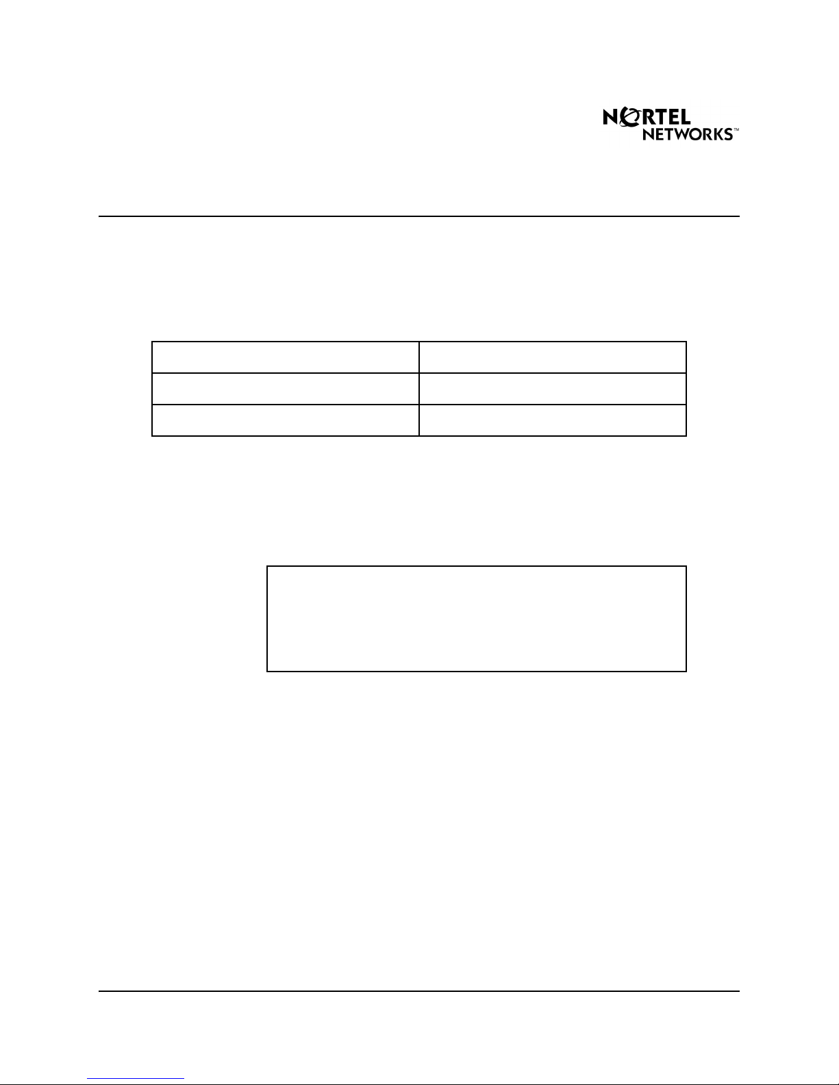
Customer Service Report Number
NTP Number
Software Release
Description
In Fiber Remote Multi-IPE Interface: Description, Installation, and
Maintenance (553-3001-022), the labels indicating the on/off positions for
the S1 and S2 switches are incorrect in Table 8, Figure 7, and Table 11.
• Figure, table, procedure, and page numbers shown below are subject
to change in the next standard release of documentation.
• Text shown below in strikethrough has been replaced or removed.
Q00628634
553-3001-022
Meridian1 Release 25.0x
IMPORTANT!
Nortel Networks 24 September 2003 1 of 4
Page 2
Documentation Release Note Number: MER-0903-017
Correction in Fiber Remote Multi-IPE Interface: Description,
Installation, and Maintenance (553-3001-022),
Standard 3.00
The on/off labels for the S1 and S2 switches have been corrected in Table 8
on page 52, Figure 7 on page 59, and Table 11 on page 81.
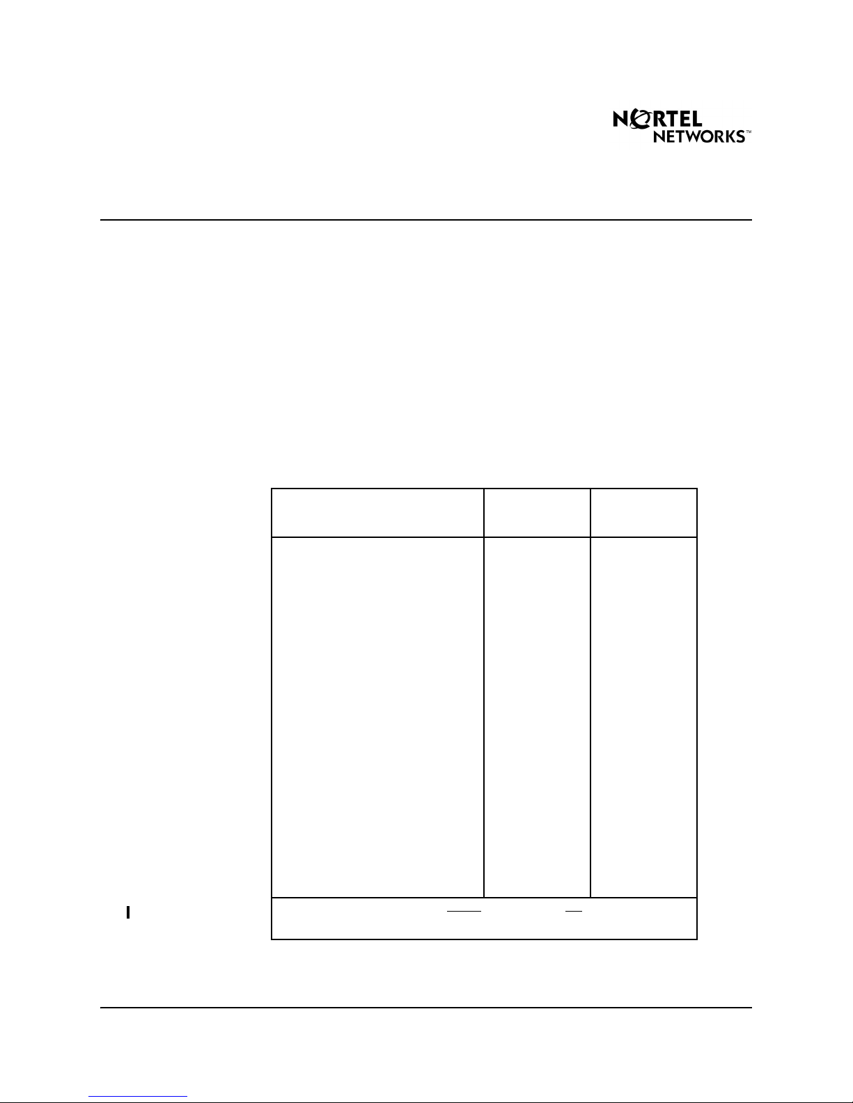
Revision in: “Installation and configuration”, page 52 of 176
Tabl e 8
Fiber Remote Multi-IPE Interface configuration
Switch and
Function Selection
Position Switch Setting
For single Fiber Remote Multi-IPE
Interface unit
Fiber Remote Multi-IPE Interface at
the MMI terminal or modem end
of the daisy-chain
Fiber Remote Multi-IPE Interface at
the SDI port end of the daisy-chain
Fiber Remote Multi-IPE Interface in
the middle of the daisy-chain
Fiber Remote Multi-IPE Interface
address in a daisy-chain and
system monitor address
Physical location of the Fiber
Remote Multi-IPE Interface
Reserved for future use S2 Positions
Note: Switch position: ON= Down
S2 switches.
S1 Position 1
and Position 2
S1 Position 1
Position 2
S1 Position 1
Position 2
S1 Position 1
Position 2
S1 Positions
3–8
S2 Position 1 ON-Remote site
3–8
Up and OFF= Up Down for S1 and
ON (at local and
remote sites)
ON
OFF
OFF
ON
OFF
OFF
Refer to Table 9
OFF-Local site
OFF
Nortel Networks 24 September 2003 2 of 4
Page 3

Documentation Release Note Number: MER-0903-017
Revision in: “Installation and configuration”, page 59 of 176
Figure 7
Installing the redundant fiber-optic link option
Remove covers from fiber connectors
Insert connctors in faceplate holes
Standoff
1 2 3 4 5 6 7 8
ON
OFF
Fiber Remote Multi-IPE Interface card
Daughterboard
1 2 3 4 5 6 7 8
ON
OFF
S1 S2
Ribbon cable
Connector
553-7124
Nortel Networks 24 September 2003 3 of 4
Page 4

Documentation Release Note Number: MER-0903-017
Revision in: “Installation and configuration”, page 81 of 176
Table 11
Switch S1 and S2 settings
Function Selection
For single Fiber Remote Multi-IPE
Interface unit
Fiber Remote Multi-IPE Interface at
the MMI terminal or modem end
of the daisy-chain
Fiber Remote Multi-IPE Interface in
the middle of the daisy-chain
Fiber Remote Multi-IPE Interface
system monitor address
Physical location of the Fiber
Remote Multi-IPE Interface
Reserved for future use S2 Positions
Note: Switch position: ON= Down
S2 switches.
Projected Inclusion in NTP
Switch and
Position
S1 Position 1
and Position 2
S1 Position 1
Position 2
S1 Position 1
Position 2
S1 Positions
3-8
S2 Position 1 ON-Remote site
3-8
Up and OFF= Up Down for S1 and
Switch Setting
ON (at local and
remote sites)
ON
OFF
OFF
OFF
Refer to Table 9
OFF
This correction will be included in the next standard release of Meridian 1 and
Succession documentation.
* Nortel Networks, the Nortel Networks logo, the Globe mark, SL-1, Meridian 1, and Succession
are trademarks of Nortel Networks.
Nortel Networks 24 September 2003 4 of 4
 Loading...