

Page 1
555-8421-215
Remote Office 9150
Installation and Administration Guide
Product release 1.0 Standard 1.0 March 2000
Page 2

NTDR84AA
Page 3

Remote Office 9150
Installation and Administration Guide
Product release: 1.0
Publication number: 555-8421-215
Document release: Standard 1.0
Date: March 2000
Copyright © 2000 Nortel Networks, All Rights Reserved
Printed in the United States of America
All information contained in this document is subject to change without notice. Nortel Networks
reserves the right to make changes to equipment design or program components, as progress in
engineering, manufacturing methods, or other circumstances may warrant.
*Nortel Networks, the Nortel Networks logo, the Globemark, How the World Shares Ideas, and
Unified Networks, Meridian 1, and SL-100 are trademarks of Nortel Networks.
PROCOMM PLUS is a trademark of Datastorm Technologies, a subsidiary of Quarterdeck
Corporation.
HYPERTERMINAL is a trademark of Hilgraeve, Incorporated.
MICROSOFT, MS-DOS, WINDOWS, and WINDOWS NT are trademarks of Microsoft Corporation.
Page 4

FCC: Customer instructions
The Remote Office 9150 unit complies with Part 68 of the FCC rules. On the bottom
side of the equipment is a label that contains, among other information, the FCC
registration number and ringer equivalence number (REN) for this equipment. If
requested, this information must be provided to the telephone company.
The Remote Office 9150 unit uses the following standard connections and codes: USOC
Code: RJ21X, Facility Interface Code: 02DU5-64, and Service Order Code: 6.0F.
The REN number shown on the label is used to determine the number of devices that can
be connected to the telephone line. Excessive RENs on the telephone line can result in
the devices not ringing in response to an incoming call. The sum of the RENs should not
exceed five (5.0). To be certain of the number of devices that can be connected to a line,
as determined by the total RENs, contact the local telephone company.
If the equipment causes harm to the telephone network, the telephone company will
notify you in advance that temporary discontinuance of service might be required.
However, if advance notice is not practical, the telephone company will notify you as
soon as possible. Also, you will be advised of your right to file a complaint with the FCC
if you believe it is necessary.
The telephone company may make changes in its facilities, equipment, operations, or
procedures that could affect the operation of the equipment. If this happens, the
telephone company will provide advance notice in order for you to make necessary
modifications to maintain uninterrupted service.
No repairs can be performed by you. If you experience trouble with this equipment,
please contact the following for repair and warranty information:
Nortel Networks
Product Service Center
640 Massman Drive. Nashville, TN 31210
Phone: 1-800-251-1758
If the equipment is causing harm to the telephone network, the telephone company
might request that you disconnect the equipment until the problem is resolved.
This equipment cannot be used on public coin phone service provided by the telephone
company. Connection to party line service is subject to state tariffs. Contact the state
public utility commission, public service commission, or corporation commission for
information.
Page 5

Industry Canada: Equipment attachment limitation
NOTICE: The Industry Canada Label identifies certified equipment. This certification
means that the equipment meets telecommunications network protective, operational,
and safety requirements as prescribed in the appropriate Terminal Equipment Technical
Requirements document(s). The Department does not guarantee that the equipment will
operate to the user’s satisfaction.
Before installing this equipment, you should ensure that it is permissible to be connected
to the facilities of the local telecommunications company. The equipment must also be
installed using an acceptable method of connection. You should be aware that
compliance with the above conditions might not prevent degradation in service in some
situations.
Repairs to certified equipment should be coordinated by a representative designated by
the supplier. Any repairs or alterations made by the user to this equipment, or equipment
malfunctions, can give the telecommunications company cause to request you to
disconnect the equipment.
You should ensure, for your own protection, that the electrical ground connections of the
power utility, telephone lines, and internal metallic water pipe system, if present, are
connected together. This precaution can be particularly important in rural areas.
Caution:
the appropriate electric inspection authority, or electrician, as appropriate.
NOTICE: The Ringer Equivalence Number (REN) assigned to each terminal device
provides an indication of the maximum number of terminals allowed to be connected to
a telephone interface. The termination on an interface can consist of any combination of
devices subject only to the requirements that the sum of the Ringer Equivalence
Numbers of all the devices does not exceed 5.
You should not attempt to make such connections yourself, but should contact
Page 6

Page 7

March 2000 Publication history
Publication history
March 2000
This is the Standard 1.0 issue of the Remote Office 9150
Installation and Administration Guide for Remote Office
9150 Release 1.0.
Installation and Administration Guide
v
Page 8

Publication history Standard 1.0
vi Remote Office 9150
Page 9

Contents
About this document xiii
About this guide . . . . . . . . . . . . . . . . . . . . . . . . . . . . . . . . . . . . . . . . . . . . . . . xiv
Skills you need . . . . . . . . . . . . . . . . . . . . . . . . . . . . . . . . . . . . . . . . . . . . . . .xviii
Related information products . . . . . . . . . . . . . . . . . . . . . . . . . . . . . . . . . . . . . xx
Conventions used in this guide. . . . . . . . . . . . . . . . . . . . . . . . . . . . . . . . . . . xxii
1
Remote Office 9150 description 1
Overview. . . . . . . . . . . . . . . . . . . . . . . . . . . . . . . . . . . . . . . . . . . . . . . . . . . . . . 2
Section A: Product description 7
Overview. . . . . . . . . . . . . . . . . . . . . . . . . . . . . . . . . . . . . . . . . . . . . . . . . . . . . . 8
What is Remote Office 9150?. . . . . . . . . . . . . . . . . . . . . . . . . . . . . . . . . . . . . 10
Remote Office 9150 hardware description. . . . . . . . . . . . . . . . . . . . . . . . . . . 13
Add-on modules description. . . . . . . . . . . . . . . . . . . . . . . . . . . . . . . . . . . . . . 17
Connection options. . . . . . . . . . . . . . . . . . . . . . . . . . . . . . . . . . . . . . . . . . . . . 19
How the Remote Office 9150 unit works. . . . . . . . . . . . . . . . . . . . . . . . . . . . 21
Section B: Feature description 31
Overview. . . . . . . . . . . . . . . . . . . . . . . . . . . . . . . . . . . . . . . . . . . . . . . . . . . . . 32
System security. . . . . . . . . . . . . . . . . . . . . . . . . . . . . . . . . . . . . . . . . . . . . . . . 36
Trunking, connection types, and call timers. . . . . . . . . . . . . . . . . . . . . . . . . . 38
Telephones . . . . . . . . . . . . . . . . . . . . . . . . . . . . . . . . . . . . . . . . . . . . . . . . . . . 41
Voice over IP features. . . . . . . . . . . . . . . . . . . . . . . . . . . . . . . . . . . . . . . . . . . 44
Port management . . . . . . . . . . . . . . . . . . . . . . . . . . . . . . . . . . . . . . . . . . . . . . 50
Station priority . . . . . . . . . . . . . . . . . . . . . . . . . . . . . . . . . . . . . . . . . . . . . . . . 52
Connection bandwidth . . . . . . . . . . . . . . . . . . . . . . . . . . . . . . . . . . . . . . . . . . 54
Local calling . . . . . . . . . . . . . . . . . . . . . . . . . . . . . . . . . . . . . . . . . . . . . . . . . . 55
Online/offline table. . . . . . . . . . . . . . . . . . . . . . . . . . . . . . . . . . . . . . . . . . . . . 57
Other supported features. . . . . . . . . . . . . . . . . . . . . . . . . . . . . . . . . . . . . . . . . 59
Administration software . . . . . . . . . . . . . . . . . . . . . . . . . . . . . . . . . . . . . . . . . 61
Installation and Administration Guide vii
Page 10

Contents Standard 1.0
2
Planning for installation 63
Overview. . . . . . . . . . . . . . . . . . . . . . . . . . . . . . . . . . . . . . . . . . . . . . . . . . . . . 64
Installation checklist . . . . . . . . . . . . . . . . . . . . . . . . . . . . . . . . . . . . . . . . . . . . 67
Physical environment . . . . . . . . . . . . . . . . . . . . . . . . . . . . . . . . . . . . . . . . . . . 71
Administration PC . . . . . . . . . . . . . . . . . . . . . . . . . . . . . . . . . . . . . . . . . . . . . 76
Network considerations . . . . . . . . . . . . . . . . . . . . . . . . . . . . . . . . . . . . . . . . . 81
Managing trunk connections. . . . . . . . . . . . . . . . . . . . . . . . . . . . . . . . . . . . . . 85
Station configuration. . . . . . . . . . . . . . . . . . . . . . . . . . . . . . . . . . . . . . . . . . . . 88
Security. . . . . . . . . . . . . . . . . . . . . . . . . . . . . . . . . . . . . . . . . . . . . . . . . . . . . . 92
Planning for future growth . . . . . . . . . . . . . . . . . . . . . . . . . . . . . . . . . . . . . . . 94
Deployment options . . . . . . . . . . . . . . . . . . . . . . . . . . . . . . . . . . . . . . . . . . . . 97
Planning the configuration . . . . . . . . . . . . . . . . . . . . . . . . . . . . . . . . . . . . . . 101
3
Installing the Remote Office 9150 unit 105
Overview. . . . . . . . . . . . . . . . . . . . . . . . . . . . . . . . . . . . . . . . . . . . . . . . . . . . 106
General safety . . . . . . . . . . . . . . . . . . . . . . . . . . . . . . . . . . . . . . . . . . . . . . . . 108
Required tools. . . . . . . . . . . . . . . . . . . . . . . . . . . . . . . . . . . . . . . . . . . . . . . . 110
Unpacking and inspecting the equipment. . . . . . . . . . . . . . . . . . . . . . . . . . . 111
Removing the Remote Office 9150 unit cover . . . . . . . . . . . . . . . . . . . . . . . 113
Installing a trunk interface or DSP application module . . . . . . . . . . . . . . . . 116
Mounting the Remote Office 9150 unit . . . . . . . . . . . . . . . . . . . . . . . . . . . . 122
Connecting the Remote Office 9150 unit. . . . . . . . . . . . . . . . . . . . . . . . . . . 129
Powering up the Remote Office 9150 unit . . . . . . . . . . . . . . . . . . . . . . . . . . 135
Installing the software. . . . . . . . . . . . . . . . . . . . . . . . . . . . . . . . . . . . . . . . . . 138
Using the Configuration Wizard to perform initial configuration . . . . . . . . 141
Testing the network connections . . . . . . . . . . . . . . . . . . . . . . . . . . . . . . . . . 155
4
Configuration Manager overview 161
Overview. . . . . . . . . . . . . . . . . . . . . . . . . . . . . . . . . . . . . . . . . . . . . . . . . . . . 162
Starting Configuration Manager. . . . . . . . . . . . . . . . . . . . . . . . . . . . . . . . . . 164
Configuration Manager description . . . . . . . . . . . . . . . . . . . . . . . . . . . . . . . 167
Using the online Help. . . . . . . . . . . . . . . . . . . . . . . . . . . . . . . . . . . . . . . . . . 175
Configuration files description . . . . . . . . . . . . . . . . . . . . . . . . . . . . . . . . . . . 176
Working with configuration files . . . . . . . . . . . . . . . . . . . . . . . . . . . . . . . . . 183
Selecting the device type for offline configuration . . . . . . . . . . . . . . . . . . . 187
Logging on to a unit . . . . . . . . . . . . . . . . . . . . . . . . . . . . . . . . . . . . . . . . . . . 189
Logging off from a unit . . . . . . . . . . . . . . . . . . . . . . . . . . . . . . . . . . . . . . . . 197
Performing a system restart or shutdown . . . . . . . . . . . . . . . . . . . . . . . . . . . 198
Closing Configuration Manager . . . . . . . . . . . . . . . . . . . . . . . . . . . . . . . . . . 201
viii Remote Office 9150
Page 11

March 2000 Contents
5
Configuring the Remote Office 9150 unit 203
Overview. . . . . . . . . . . . . . . . . . . . . . . . . . . . . . . . . . . . . . . . . . . . . . . . . . . . 204
Section A: System settings 211
Overview. . . . . . . . . . . . . . . . . . . . . . . . . . . . . . . . . . . . . . . . . . . . . . . . . . . . 212
Configuring the system settings . . . . . . . . . . . . . . . . . . . . . . . . . . . . . . . . . . 215
Section B: IP addresses 221
About IP addresses . . . . . . . . . . . . . . . . . . . . . . . . . . . . . . . . . . . . . . . . . . . . 222
Configuring the Remote Office 9150 unit’s IP interface . . . . . . . . . . . . . . . 227
Section C: RLC connection information 229
Overview. . . . . . . . . . . . . . . . . . . . . . . . . . . . . . . . . . . . . . . . . . . . . . . . . . . . 230
Configuring the RLC connection information . . . . . . . . . . . . . . . . . . . . . . . 231
Configuring the security level. . . . . . . . . . . . . . . . . . . . . . . . . . . . . . . . . . . . 235
Section D: Trunk interface information 239
About trunks and trunk groups . . . . . . . . . . . . . . . . . . . . . . . . . . . . . . . . . . . 240
Configuring BRI trunks . . . . . . . . . . . . . . . . . . . . . . . . . . . . . . . . . . . . . . . . 242
Configuring trunk groups . . . . . . . . . . . . . . . . . . . . . . . . . . . . . . . . . . . . . . . 246
Section E: Stations 251
Station overview . . . . . . . . . . . . . . . . . . . . . . . . . . . . . . . . . . . . . . . . . . . . . . 252
Defining stations. . . . . . . . . . . . . . . . . . . . . . . . . . . . . . . . . . . . . . . . . . . . . . 260
Defining a fax station . . . . . . . . . . . . . . . . . . . . . . . . . . . . . . . . . . . . . . . . . . 266
6
Using Remote Office 9150 stations 271
Modes of operation. . . . . . . . . . . . . . . . . . . . . . . . . . . . . . . . . . . . . . . . . . . . 272
Making and receiving calls. . . . . . . . . . . . . . . . . . . . . . . . . . . . . . . . . . . . . . 276
Indicator updates. . . . . . . . . . . . . . . . . . . . . . . . . . . . . . . . . . . . . . . . . . . . . . 280
Display messages . . . . . . . . . . . . . . . . . . . . . . . . . . . . . . . . . . . . . . . . . . . . . 282
Telephone features operation . . . . . . . . . . . . . . . . . . . . . . . . . . . . . . . . . . . . 285
Going online and offline. . . . . . . . . . . . . . . . . . . . . . . . . . . . . . . . . . . . . . . . 289
Installation and Administration Guide ix
Page 12

Contents Standard 1.0
7
Administration 291
Overview. . . . . . . . . . . . . . . . . . . . . . . . . . . . . . . . . . . . . . . . . . . . . . . . . . . . 292
Changing the administration password. . . . . . . . . . . . . . . . . . . . . . . . . . . . . 294
Section A: Performing backups and restores 299
Overview. . . . . . . . . . . . . . . . . . . . . . . . . . . . . . . . . . . . . . . . . . . . . . . . . . . . 300
Creating a backup configuration file . . . . . . . . . . . . . . . . . . . . . . . . . . . . . . 301
Restoring the configuration . . . . . . . . . . . . . . . . . . . . . . . . . . . . . . . . . . . . . 303
Section B: Working with system logs 309
Overview. . . . . . . . . . . . . . . . . . . . . . . . . . . . . . . . . . . . . . . . . . . . . . . . . . . . 310
Displaying logs . . . . . . . . . . . . . . . . . . . . . . . . . . . . . . . . . . . . . . . . . . . . . . . 311
Resizing logs. . . . . . . . . . . . . . . . . . . . . . . . . . . . . . . . . . . . . . . . . . . . . . . . . 313
Clearing logs. . . . . . . . . . . . . . . . . . . . . . . . . . . . . . . . . . . . . . . . . . . . . . . . . 314
Section C: Viewing statistics 315
Overview. . . . . . . . . . . . . . . . . . . . . . . . . . . . . . . . . . . . . . . . . . . . . . . . . . . . 316
Trunk Connection Statistics screen. . . . . . . . . . . . . . . . . . . . . . . . . . . . . . . . 318
Bandwidth Connection Statistics screen. . . . . . . . . . . . . . . . . . . . . . . . . . . . 321
Caller Information Statistics screen . . . . . . . . . . . . . . . . . . . . . . . . . . . . . . . 324
Hardware Statistics screen . . . . . . . . . . . . . . . . . . . . . . . . . . . . . . . . . . . . . . 327
Local Call Statistics screen. . . . . . . . . . . . . . . . . . . . . . . . . . . . . . . . . . . . . . 330
Remote Call Statistics screen . . . . . . . . . . . . . . . . . . . . . . . . . . . . . . . . . . . . 332
Section D: Performing upgrades 335
Overview. . . . . . . . . . . . . . . . . . . . . . . . . . . . . . . . . . . . . . . . . . . . . . . . . . . . 336
Verifying the firmware and software version. . . . . . . . . . . . . . . . . . . . . . . . 338
Obtaining the latest upgrade file. . . . . . . . . . . . . . . . . . . . . . . . . . . . . . . . . . 340
Extracting upgrade files from the download file . . . . . . . . . . . . . . . . . . . . . 342
Performing a firmware upgrade . . . . . . . . . . . . . . . . . . . . . . . . . . . . . . . . . . 344
Performing a software upgrade. . . . . . . . . . . . . . . . . . . . . . . . . . . . . . . . . . . 348
8
Troubleshooting 349
Overview. . . . . . . . . . . . . . . . . . . . . . . . . . . . . . . . . . . . . . . . . . . . . . . . . . . . 350
Before you begin. . . . . . . . . . . . . . . . . . . . . . . . . . . . . . . . . . . . . . . . . . . . . . 352
Remote Office 9150 LEDs . . . . . . . . . . . . . . . . . . . . . . . . . . . . . . . . . . . . . . 353
Digital telephone. . . . . . . . . . . . . . . . . . . . . . . . . . . . . . . . . . . . . . . . . . . . . . 355
Device connectivity . . . . . . . . . . . . . . . . . . . . . . . . . . . . . . . . . . . . . . . . . . . 360
Software problems . . . . . . . . . . . . . . . . . . . . . . . . . . . . . . . . . . . . . . . . . . . . 364
Using Configuration Manager’s Ping. . . . . . . . . . . . . . . . . . . . . . . . . . . . . . 366
Recovering from a catastrophic failure. . . . . . . . . . . . . . . . . . . . . . . . . . . . . 369
x Remote Office 9150
Page 13

March 2000 Contents
A
Network engineering guidelines 371
Overview. . . . . . . . . . . . . . . . . . . . . . . . . . . . . . . . . . . . . . . . . . . . . . . . . . . . 372
Remote Office traffic engineering . . . . . . . . . . . . . . . . . . . . . . . . . . . . . . . . 375
Assessing WAN link resources. . . . . . . . . . . . . . . . . . . . . . . . . . . . . . . . . . . 386
Quality of Service evaluation process overview. . . . . . . . . . . . . . . . . . . . . . 393
Setting the Quality of Service. . . . . . . . . . . . . . . . . . . . . . . . . . . . . . . . . . . . 398
Measuring the intranet Quality of Service . . . . . . . . . . . . . . . . . . . . . . . . . . 403
Reducing delays . . . . . . . . . . . . . . . . . . . . . . . . . . . . . . . . . . . . . . . . . . . . . . 412
Implementing Quality of Service in IP networks . . . . . . . . . . . . . . . . . . . . . 416
B
Planning forms 421
Overview. . . . . . . . . . . . . . . . . . . . . . . . . . . . . . . . . . . . . . . . . . . . . . . . . . . . 422
Section A: Remote Office 9150 forms 425
Completing the Remote Office 9150 forms . . . . . . . . . . . . . . . . . . . . . . . . . 426
Configuration Information—Stations. . . . . . . . . . . . . . . . . . . . . . . . . . . . . . 428
Configuration Information—ISDN BRI Modules . . . . . . . . . . . . . . . . . . . . 432
Configuration Information—Network Connections. . . . . . . . . . . . . . . . . . . 435
Configuration Information—Dialing Plans . . . . . . . . . . . . . . . . . . . . . . . . . 436
System expansion worksheet . . . . . . . . . . . . . . . . . . . . . . . . . . . . . . . . . . . . 437
Section B: Meridian Internet Gateway Reach Line Card forms 441
Completing the MIG RLC forms . . . . . . . . . . . . . . . . . . . . . . . . . . . . . . . . . 442
Connection Information—16 ports. . . . . . . . . . . . . . . . . . . . . . . . . . . . . . . . 444
Connection Information—32 ports. . . . . . . . . . . . . . . . . . . . . . . . . . . . . . . . 449
Online/Offline Table Configuration . . . . . . . . . . . . . . . . . . . . . . . . . . . . . . . 457
System expansion worksheet . . . . . . . . . . . . . . . . . . . . . . . . . . . . . . . . . . . . 458
C
Sample configuration files 461
Example of a network. . . . . . . . . . . . . . . . . . . . . . . . . . . . . . . . . . . . . . . . . . 462
Voice port configuration on the Meridian 1 PBX. . . . . . . . . . . . . . . . . . . . . 464
Data port configuration on the Meridian 1 PBX. . . . . . . . . . . . . . . . . . . . . . 466
MIG RLC configuration . . . . . . . . . . . . . . . . . . . . . . . . . . . . . . . . . . . . . . . . 468
Remote Office 9150 unit. . . . . . . . . . . . . . . . . . . . . . . . . . . . . . . . . . . . . . . . 472
Installation and Administration Guide xi
Page 14

Contents Standard 1.0
D
Connection pin-out tables 475
TELCO 1 connector pin-out table . . . . . . . . . . . . . . . . . . . . . . . . . . . . . . . . 476
TELCO 2 connector pin-out table . . . . . . . . . . . . . . . . . . . . . . . . . . . . . . . . 478
Ethernet connector pin-out table. . . . . . . . . . . . . . . . . . . . . . . . . . . . . . . . . . 480
Admin (serial) connector pin-out table. . . . . . . . . . . . . . . . . . . . . . . . . . . . . 481
Power connector pin-out table . . . . . . . . . . . . . . . . . . . . . . . . . . . . . . . . . . . 482
Glossary 483
Fields index 505
Index 511
xii Remote Office 9150
Page 15

Preface
About this document
In this preface
About this guide xiv
Skills you need xviii
Related information products xx
Conventions used in this guide xxii
Installation and Administration Guide xiii
Page 16

About this document Standard 1.0
About this guide
Introduction
The Remote Office 9150 Installation and Administration Guide describes how to
install, configure, and manage the Remote Office 9150 unit in a branch office.
Who should read this guide
This guide is for the following individuals who are responsible for the
installation, configuration, and day-to-day management of the Remote Office
9150 unit system:
Nortel Networks distributors
■
telecom network managers and administrators
■
data network managers and administrators
■
branch office managers and administrators
■
Assumptions
This document assumes that you have the skills listed on page xviii.
How to use this guide
This guide explains, step-by-step, how to install, configure, and use the Remote
Office 9150 unit product. To get an overview of what you need to do, review this
guide before beginning Remote Office 9150 unit installation and configuration.
When you are ready to begin, follow the steps in the order in which they are
presented. This helps you to achieve a successful installation.
In this guide
Chapter 1, “Remote Office 9150 description”
This chapter describes the Remote Office 9150 system, how it works, and its
features.
xiv Remote Office 9150
Page 17

March 2000 About this document
Chapter 2, “Planning for installation”
This chapter helps you to plan for Remote Office 9150 unit installation and
configuration. This chapter includes topics such as
choosing a suitable location
■
issues to consider when incorporating the Remote Office 9150 unit product
■
into your networks
managing system resources
■
planning network security
■
planning user station configuration
■
installation checklists
■
methods for implementing the Remote Office 9150 unit into your network
■
gathering information for configuration
■
planning for future growth
■
Chapter 3, “Installing the Remote Office 9150 unit”
This chapter explains how to
install and connect the Remote Office 9150 unit
■
install or replace trunk interface and DSP application modules
■
install and start the Configuration Manager software
■
Chapter 4, “Configuration Manager overview”
This chapter describes the Configuration Manager screens. It also describes the
conventions used in this guide to present instructions for working with the
screens.
Chapter 5, “Configuring the Remote Office 9150 unit”
This chapter explains how to use the Configuration Manager software to
configure
trunks used by the Remote Office 9150 unit
■
connection information needed to establish connections between the
■
MIG RLC on the host PBX and the Remote Office 9150 unit at the branch
office
user stations connected to the Remote Office 9150 unit
■
Installation and Administration Guide xv
Page 18

About this document Standard 1.0
Chapter 6, “Using Remote Office 9150 stations”
This chapter describes digital telephone usage and features as they pertain to
Remote Office 9150.
Chapter 7, “Administration”
This chapter describes how to perform periodic administration tasks, such as
performing backups, restores, and upgrades, and viewing system logs and
statistics.
Chapter 8, “Troubleshooting”
This chapter describes how to determine why the Remote Office 9150 and its
connected telephones are not working.
Appendix A, “Network engineering guidelines”
This appendix provides guidelines for evaluating and setting Quality of Service
on your IP network. If you install the Remote Office product in your IP network
without performing the preliminary assessments that are described, this can
result in unacceptable degradation in voice service to users.
Appendix B, “Planning forms”
This appendix provides sample forms to help you
plan the Remote Office 9150 unit configuration
■
determine what you need to expand the Remote Office 9150 unit’s voice
■
processing capabilities
Appendix C, “Sample configuration files”
This appendix provides the following:
a sample network diagram that shows one host site (MIG RLC installed on
■
the host PBX) and one Remote Office 9150 unit (with one user station)
sample configurations using information from the network diagram
■
The purpose of this appendix is to demonstrate the relationship between
configuration settings on each unit in the network.
Appendix D, “Connection pin-out tables”
This section provides pin-out tables for each Remote Office 9150 unit connector.
xvi Remote Office 9150
Page 19

March 2000 About this document
Glossary
Many terms in this manual have meanings specific to the telecommunications
and data networking fields, or specific to the Remote Office 9150 unit. You can
find the definitions of terms used in this manual, as well as a few related terms.
Indexes
The Fields index helps you to locate information about the fields on the
Configuration Manager screens. Use the index when you want to know the
function of the field.
The main index provides an alternative method of locating information in this
guide.
Installation and Administration Guide xvii
Page 20

About this document Standard 1.0
Skills you need
Introduction
This section describes the skills and knowledge you need to use this guide
effectively.
Nortel Networks product knowledge
Knowledge of, or experience with, the following Nortel Networks products is
helpful when working with the Remote Office 9150 unit:
the Meridian 1 switch
■
Meridian digital telephones
■
Telecommunications experience
Knowledge of, or experience with, telecommunications is helpful when working
with the Remote Office 9150 unit:
Extended Digital Line Cards (XDLCs) and how they work
■
configuring voice and data ports
■
configuring ISDN BRI, PRI (or other types of trunks)
■
establishing telephone connections
■
Data networking experience
Knowledge of, or experience with, data networking is helpful when working
with the Remote Office 9150 unit:
networking fundamentals and concepts
■
IP protocol
■
network addressing and routing
■
xviii Remote Office 9150
Page 21

March 2000 About this document
network traffic analysis and provisioning
■
network security
■
Voice over IP (general knowledge)
■
PC experience or knowledge
Knowledge of, or experience with, the following PC tasks is helpful when
administering the Remote Office 9150 unit:
general knowledge of Microsoft Windows
■
software installation
■
network configuration
■
Other experience or knowledge
Other types of experience or knowledge that can be useful include the following:
analytical skills
■
troubleshooting skills
■
Installation and Administration Guide xix
Page 22

About this document Standard 1.0
Related information products
Introduction
This section lists information products where you can find additional
information.
Meridian 1 documents
The following documents describe how to establish telephone and trunk
connections between the Remote Office 9150 unit and the BIX in-building
cross-connect system:
Meridian 1 Installation planning (NTP 553-3001-120)
■
Telephone and attendant console installation (NTP 553-3001-215)
■
BIX* In-Building Cross-Connect System Material Installation and
■
Servicing (Wall-Mounted System) (NTP 631-4511-200)
Remote Office 9150 and MIG RLC documents
Remote Office and MIG RLC Release Notes (NTP 555-8421-102)
The Release Notes describe the features and known problems for the Meridian
Internet Gateway Reach Line Card (MIG RLC) and Remote Office 9150 branch
office system.
The printed copy might supersede the copy provided on the CD-ROM. You can
obtain the most up-to-date version from the Nortel Networks web site. For
download instructions, see “How to obtain the product documentation and
CD-ROMs” on page xxi.
Meridian Internet Gateway Reach Line Card Installation and
Administration Guide (NTP 555-8421-210)
This document, written for both the Meridian 1 installer and administrator,
explains how to install and configure the Meridian Internet Gateway Reach Line
Card on the Meridian 1 PBX.
xx Remote Office 9150
Page 23

March 2000 About this document
Installer’s Notes
The following Installer’s Notes are quick reference documents that are provided
with the component discussed in the document:
Meridian Internet Gateway Reach Line Card Installer’s Notes
■
Remote Office 9150 and MIG RLC DSP Application Module Installer’s
■
Notes
Remote Office 9150 Trunk Interface Module Installer’s Notes
■
Each document summarizes the installation and configuration procedures for the
component and provides cross-references to other documents for more detailed
information.
Note: You cannot order these documents separately.
CD-ROMs
The following CD-ROMs are available for the Remote Office 9150 unit:
Remote Office Product CD-ROM, which contains
■
documentation in Adobe Acrobat Reader (PDF) format
■
firmware
■
Configuration Manager software
■
Remote Office Technical Training Course 100 CD-ROM
■
The Technical Training CD-ROM contains a web-based course for Nortel
Networks distributors, and administrators of Nortel Networks customers.
The course explains how to install, configure, and manage the MIG RLC
and Remote Office 9150 unit.
How to obtain the product documentation and CD-ROMs
You can order the printed documentation and CD-ROMs from your Nortel
Networks distributor.
You can also download the documentation in Adobe Acrobat Reader (PDF)
format from the Nortel Networks web site. For more information, refer to the
Remote Office and MIG RLC Release Notes (NTP 555-8421-102).
Installation and Administration Guide xxi
Page 24
About this document Standard 1.0
Conventions used in this guide
Introduction
This section describes the conventions used in this guide.
Precautionary messages
Note: A note describes the secondary results of procedures or commands, or
special conditions under which you must use a procedure or command.
ATTENTION
.
.
.
Provides information essential to the completion of a task.
CAUTION
Risk of data loss or equipment damage
Cautions you against unsafe practices or potential hazards, such as
equipment damage, service interruption, or loss of data.
WARNING
Risk of minor personal injury
Warns you of a potentially hazardous situation that can result in
minor or moderate injury.
DANGER
Risk of death or serious personal injury
Alerts you to an immediate hazard that can result in death or
serious injury.
xxii Remote Office 9150
Page 25

March 2000 About this document
DANGER
.
Risk of electric shock
Alerts you to an immediate hazard that can result in death or
serious injury through high voltage or electric shock.
How this guide presents instructions for selecting menu options
To simplify the instructions for selecting options from the menu, this guide
abbreviates the selection path. For example, if a procedure requires you to
choose Over IP from the Remote Connectivity menu, which is under the Tests
menu, this guide uses the following style:
From the menu, choose Tests
Remote Connectivity ➝ Over IP.
➝
How this guide presents instructions for displaying property sheets
To simplify the procedures for accessing property sheets throughout this guide,
the instructions for displaying a particular property sheet are summarized in a
“Getting there” statement.
The procedure for displaying the screen that you need depends on whether you
are
■
performing an online configuration (that is, you are connected to a node by
serial port or Telnet)
■
performing an offline configuration (that is, you are not connected to a
node)
Example
Getting there
9150
➝
Configuration Manager ➝ IP Configuration
The long instruction for this example is shown on the next page.
Installation and Administration Guide xxiii
Page 26

About this document Standard 1.0
1
Do the following:
IF THEN
you are performing an offline
configuration
select the device type as described in
“Selecting the device type for offline
configuration” on page 187.
you are performing an online
configuration
connect to, and then log on to the node
as described in “Logging on to a unit” on
page 189.
2
In the left pane, click the plus sign beside Configuration Manager to expand
the node list.
3
Click IP Configuration.
Result:
The IP Configuration property sheet for the Remote Office 9150
unit appears in the right pane.
xxiv Remote Office 9150
Page 27

Chapter 1
Remote Office 9150 description
In this chapter
Overview 2
Section A: Product description 7
Section B: Feature description 31
Installation and Administration Guide 1
Page 28

Remote Office 9150 description Standard 1.0
Overview
Introduction
The Remote Office 9150 unit provides full-featured host Meridian 1 PBX
services to as many as 32 users located in your office.
Components
The Remote Office 9150 solution consists of the following components:
Meridian Internet Gateway Reach Line Card (MIG RLC)
■
The MIG RLC is installed in the Meridian 1 PBX at the host location and
relays voice and signaling information from the digital telephones
connected at the Remote Office 9150 site to the Meridian 1 PBX at the host
site.
Remote Office 9150 unit
■
The Remote Office 9150 unit is installed in your office. It relays voice and
signaling information between the digital telephones in your office to the
Meridian 1 PBX at the host location.
10BaseT Ethernet and ISDN Basic Rate Interface (BRI) connections
■
These connections provide the voice and data connections between the
Remote Office 9150 unit and the host PBX.
ISDN BRI trunk interface modules are supported for the following:
■
U interface
■
S/T interface
■
optional Digital Signal Processor (DSP) application modules
■
You can add these modules to increase the system’s voice processing
capacity.
2 Remote Office 9150
Page 29

March 2000 Remote Office 9150 description
What does the Remote Office 9150 unit do?
The Remote Office 9150 unit uses the Voice over IP technology to route voice
conversation and phoneset control signals between your office and the host PBX
over your existing IP data network. The Remote Office 9150 unit can also route
calls over the circuit-switched network.
This is accomplished using the following components:
the Remote Office 9150 unit located in your office
■
the MIG RLC located on the Meridian 1 PBX at the host site
■
These two components, along with the 10BaseT Ethernet and ISDN BRI
connections, extend the host PBX services to users in your office.
Installation and Administration Guide 3
Page 30
Remote Office 9150 description Standard 1.0
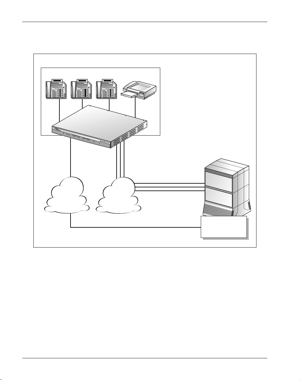
The illustration below shows the connection between a Remote Office 9150 unit
and a MIG RLC.
Remote site 1: Branch office
Up to 32 digital telephones Fax machine
Remote Office 9150
PO
WER
ETHERN
ET
T
X
R
X
C
O
L
L
1
L
1
MODULE
L
2
2
L
1
L
2
L
1
L
2
43
L
1
V.35
L
2
T
S
X
TATUS
R
X
Ethernet
Central
office
trunks
(ISDN BRI)
ISDN PRI
Corporate office
Meridian 1 PBX
Corporate
WAN
Telephone
Network
Meridian Internet
Public
Ethernet
Gateway Reach
Line Card
G101391
Telephone call modes
Calls can be placed through the Remote Office 9150 unit in any of the following
modes:
host-controlled mode
■
When a call is processed through the host PBX, the call is in hostcontrolled call mode. The call can be routed over the IP network or the
circuit-switched network.
4 Remote Office 9150
Page 31

March 2000 Remote Office 9150 description
local-controlled call mode
■
When a call is processed through the local PSTN, the call is in localcontrolled call mode.
Placing calls
To place a call in host-controlled mode, users can pick up the handset or press
the primary (host) line key, and then dial the number of the party they are
calling.
To place a call in local-controlled mode, users can pick up the handset or press
the secondary (local) line key, and then do one of the following:
to place an external call: dial the trunk access code to obtain an outgoing
■
trunk, then dial the number of the party they are calling
to place an internal call: dial the extension of another station in the same
■
office
Product features
The Remote Office 9150 unit offers the following features:
system security that supports three security levels—no security, calling line
■
identification (CLID), and security identifier
trunking allocation that automatically allocates trunk bandwidth as it is
■
needed
support for Meridian digital telephones, telephone modules, and standard
■
calling features
Voice over IP features that automatically switch from the IP network to the
■
circuit-switched network when the voice Quality of Service (QoS) falls
below a predetermined threshold, and back to the IP network when the QoS
returns to normal
Voice packet features include voice compression, jitter attenuation, and
silence suppression.
permanent or demand connections
■
If the connection is defined as call on demand, minimum call duration and
idle timers can be configured.
Installation and Administration Guide 5
Page 32

Remote Office 9150 description Standard 1.0
single ports, multi-user ports, and dynamic port pooling that assigns users
■
to the first available port
the ability to ensure QoS for specific users
■
This is done by assigning more priority to those users. There are four levels
of priority:
high
■
normal
■
IP only
■
circuit-switched only
■
local calling that allows you to place calls to other extensions within your
■
office, or to telephones in your local community
an online/offline table that is configured on the MIG RLC for scheduling
■
times
that the ISDN BRI connection to the host PBX is made available to the
■
Remote Office 9150 site
Note: When the Remote Office 9150 unit is in offline mode, calls
cannot be made or received through the host PBX over the IP or circuitswitched network.
at which all telephones in your office can use only the local PSTN
■
service
This allows you to ensure that unwanted ISDN BRI telephone calls through
the host PBX are disabled after business hours.
an emergency service number that can be programmed with your local
■
emergency number
an analog port that can send and receive faxes
■
administrative tools that allow you to perform a variety of administrative
■
tasks, such as
changing the administration password
■
making configuration changes
■
viewing the system logs and statistics
■
performing upgrades, backups, and restores
■
6 Remote Office 9150
Page 33

March 2000 Remote Office 9150 description
Section A: Product description
In this section
Overview 8
What is Remote Office 9150? 10
Remote Office 9150 hardware description 13
Add-on modules description 17
Connection options 19
How the Remote Office 9150 unit works 21
Installation and Administration Guide 7
Page 34

Remote Office 9150 description Standard 1.0
Overview
Introduction
This section provides a brief description of each Remote Office 9150 unit
feature.
Hardware
The Remote Office 9150 unit is installed in your office and can be mounted on a
desk, in a rack, or on the wall. The unit contains LED displays and network
connectors, and is shipped with a 110/220 V power supply and an RS-232 serial
cable.
Add-on modules
The Remote Office 9150 unit can support up to four ISDN BRI (U or S/T) trunk
interface modules and up to three Digital Signal Processor (DSP) application
modules.
Connection options
Communications between the Remote Office 9150 unit in your office and the
MIG RLC on the host PBX take place using 10BaseT Ethernet and ISDN Basic
Rate Interface (BRI) connections. An analog port for fax machines is also
provided.
How the Remote Office 9150 unit works
There are two major components to the Remote Office 9150 unit:
the Remote Office 9150 unit located in your office
■
the MIG RLC located on the Meridian 1 PBX at the host site
■
These two components, along with the connection options described on page 19,
extend the host PBX services to users in your office.
8 Remote Office 9150
Page 35

March 2000 Remote Office 9150 description
The Remote Office 9150 unit can operate in
host-controlled mode: calls are routed through the host PBX
■
local-controlled mode: calls are routed through the local PSTN, or to other
■
stations in the same office
To understand how calls are routed in the various modes, see the sample
illustrations beginning on page 24.
Installation and Administration Guide 9
Page 36

Remote Office 9150 description Standard 1.0
What is Remote Office 9150?
Introduction
Remote Office 9150 is a product that provides full-featured host Meridian 1
PBX services to as many as 32 users located in your office.
The Remote Office 9150 unit uses the Voice over IP technology to route voice
conversation and phoneset control signals between your office and the host PBX
over your existing IP data network.
The Remote Office 9150 unit can also use the circuit-switched network to route
calls if
the voice QoS degrades below predefined thresholds
■
In this case, Nortel Networks’ patented QoS transitioning technology
automatically transitions calls to the circuit-switched network when the
voice QoS degrades. Calls transition back to the IP network when the QoS
returns to normal.
you are not yet ready to use the IP network to route voice calls
■
You can configure the Remote Office 9150 unit to use only the circuitswitched network, and implement the IP network functionality when you
are ready.
This section provides a brief description of each component used in a Remote
Office 9150 system.
Meridian Internet Gateway Reach Line Card
The Meridian Internet Gateway Reach Line Card (MIG RLC) is installed in the
Meridian 1 PBX at the host location. The MIG RLC provides service for up to
16 ports on a 1-slot card, or 32 ports on a 2-slot card. It emulates a standard
digital line card (XDLC), providing PBX functionality for telephones at remote
locations (including sites using the Remote Office 9150 unit).
10 Remote Office 9150
Page 37

March 2000 Remote Office 9150 description
The MIG RLC relays voice and signaling information between the digital
telephones connected at the Remote Office 9150 site to the Meridian 1 PBX at
the host site. Like the Remote Office 9150 unit, the MIG RLC can route calls
over the IP network or the circuit-switched network, or both when the QoS
transitioning technology feature is configured.
For a more detailed description, refer to the Meridian Internet Gateway Reach
Line Card Installation and Administration Guide (NTP 555-8421-210).
Remote Office 9150 unit
The Remote Office 9150 unit installed in your office provides PBX functionality
for up to 32 digital telephones. Voice and signaling information between the
digital telephones connected at your office and the MIG RLC installed on the
Meridian 1 PBX at the host location is relayed over one or both of the following:
IP network
■
circuit-switched network
■
For more details, see “Remote Office 9150 hardware description” on page 13.
10BaseT Ethernet and ISDN BRI connections
These connections provide the voice and data connections between the Remote
Office 9150 unit and the host PBX. See “Connection options” on page 19 for a
more detailed description.
Optional trunk interface modules
You can install up to four ISDN BRI U or S/T interface modules in the Remote
Office 9150 unit. They provide the interface to the ISDN BRI lines provided by
your telephone service provider, and are used to route calls over the circuitswitched network.
Optional Digital Signal Processor application modules
You can install up to three Digital Signal Processor (DSP) application modules
to increase the Remote Office 9150 unit’s voice processing capacity. (See “Add-
on modules description” on page 17).
Installation and Administration Guide 11
Page 38

Remote Office 9150 description Standard 1.0
Configuration Manager
Use the following tools to configure the Remote Office 9150 unit:
for first-time configuration: Configuration Wizard
■
The Configuration Wizard provides the ability to configure only the
minimum information needed to get the Remote Office 9150 unit up and
running.
For more details, see “Using the Configuration Wizard to perform initial
configuration” on page 141.
for ongoing configuration and administration: Configuration Manager
■
For more details, see the following:
Chapter 4, “Configuration Manager overview”
■
Chapter 5, “Configuring the Remote Office 9150 unit”
■
Chapter 7, “Administration”
■
12 Remote Office 9150
Page 39

March 2000 Remote Office 9150 description
Remote Office 9150 hardware description
Introduction
The Remote Office 9150 unit is installed in your office and can be mounted on a
desk, in a rack, or on the wall. This section describes the LED displays, power
supply, cables, and connectors for the unit.
LEDs on the Remote Office 9150 unit
The following diagram shows the LEDs on the front panel of the Remote Office
9150 unit.
P
O
W
E
R
E
T
H
E
R
N
E
T
T
X
R
X
C
O
L
L
1
L
Power
1
Ethernet Modules V.35 Status
M
L
2
O
D
U
L
E
L
1
L
2
L
1
L
2
432
1
V
.3
L
2L
5
T
S
X
T
A
T
U
R
S
X
Note: The V.35 LEDs are for future use.
G101402
Installation and Administration Guide 13
Page 40

Remote Office 9150 description Standard 1.0
The operational status of the Remote Office 9150 unit is indicated by these
LEDs as described in the following table.
LED type LED name Description
Power On When lit, this LED indicates that power is
present.
Ethernet COLL When flashing, this LED indicates that a
collision has occurred on the Ethernet
network.
TX When flashing, this LED indicates that data is
being transmitted by the Remote Office 9150
unit over the Ethernet network.
RX When flashing, this LED indicates that data is
being presented to the Remote Office 9150
unit over the Ethernet network.
Module L1 and L2 L1 LED:
not lit: there is no D-channel activity
■
flashing: the D-channel is active but the
■
B-channel is not active
lit solid: both the D- and B-channels are
■
active
L2 LED:
not lit: the B-channel is not active
■
lit: the B-channel is active
■
V.35 TX For future use.
RX For future use.
Boot status Status Indicates the health of the Remote Office
9150 unit. This LED stays lit when the power
on self-test is successful. If it goes out, there
is a problem.
14 Remote Office 9150
Page 41

March 2000 Remote Office 9150 description
Note: Since Ethernet traffic has a nominal speed of 10 Mbps, the flashing
Ethernet COLL, TX, RX LEDs are cosmetic. They do not reflect real-time
traffic patterns or packets.
Connectors
The following connections are made from the rear panel of the Remote Office
9150 unit to the telephone and data networks:
Two 25-pair connectors (labeled TELCO 1 and TELCO 2) provide tip and
■
ring connections to user stations (telephones) and central office trunks
(ISDN BRI).
These connections provide the interface to the telephone network and the
Public Switched Telephone Network (PSTN).
An RJ-45 connector (labeled ETHERNET) provides a 10BaseT Ethernet
■
connection.
This connection provides the ability to pass both voice and data traffic over
the existing Ethernet network.
A DB-9 connector (labeled ADMIN) provides an RS-232 serial port
■
connection.
You can use this serial port connection to configure a Remote Office 9150
unit that is directly connected to a PC.
The DB-25 connector (labeled V.35) is for future use.
■
Refer to Chapter 2, “Planning for installation,” for a detailed description of
cables and connectors.
Mounting options
The Remote Office 9150 unit can be mounted on a desk, in a rack, or on the
wall.
Universal power supply
The Remote Office 9150 unit includes an auto-sensing 110/220 V power supply
that is compatible with commercially available UPS systems. See the diagram
on page 16.
Installation and Administration Guide 15
Page 42

Remote Office 9150 description Standard 1.0
Remote Office 9150 power supply
TELCO 1 ETHERNET TELCO 2 POWER ADMIN
Remote Office 9150
V.35
Remote Office
9150
cable
To wall
outlet
Power supply
Power cable
G101412
16 Remote Office 9150
Page 43

March 2000 Remote Office 9150 description
Add-on modules description
Introduction
The Remote Office 9150 unit can support trunk interface modules, such as ISDN
BRI U or S/T interfaces, and up to three DSP application modules.
Optional trunk interface modules
The Remote Office 9150 unit can support up to four U or S/T ISDN BRI
interfaces. Each module supports one ISDN BRI line (with two B-channels)
from the local telephone service provider.
Initially, the Remote Office 9150 unit ships with no ISDN BRI modules
installed.
ISDN BRI module
Remote Office ISDN BRI module
U interface (NTDR74xx)
S/T interface (NTDR75xx)
G101420
Installation and Administration Guide 17
Page 44

Remote Office 9150 description Standard 1.0
Optional DSP application modules
DSPs convert voice and fax into digital data for transport over the IP and circuitswitched networks. Initially, the Remote Office 9150 unit ships with the ability
to support up to eight simultaneous calls through a DSP that is built into the
Remote Office 9150 unit’s motherboard. To add support for up to 32
simultaneous calls, you must install DSP application modules. Up to three DSP
application modules are supported. Each module provides up to eight more
simultaneous calls.
In addition, you can configure the Remote Office 9150 unit for blocking with
only enough modules to support the maximum number of simultaneous calls.
For example, a Remote Office 9150 unit that is equipped with a single DSP
application module supports 16 simultaneous calls, for a ratio of 2:1 blocking.
For more details, see “Planning for future growth” on page 94.
DSP application module
Remote Office DSP module (NTDR73xx)
G101388
18 Remote Office 9150
Page 45

March 2000 Remote Office 9150 description
Connection options
Introduction
Communications between the Remote Office 9150 unit in your office and the
host PBX take place using 10BaseT Ethernet or ISDN BRI connections, or both.
This section provides a description of each of these connections.
10BaseT Ethernet interface
Voice over IP technology is used to carry voice conversation and phoneset
control signals over your IP network to the host PBX. The voice data is
forwarded as UDP/IP packets, and the signaling data is forwarded as TCP/IP
packets.
ISDN BRI lines to PSTN
The PSTN provides a cost-effective alternative to leased lines. You can use
ISDN BRI lines at the Remote Office 9150 site to make local calls without
involving the host PBX. You can also choose to use the ISDN BRI lines instead
of the IP network to route calls through the host PBX.
To use ISDN BRI lines, you must install trunk interface modules. The Remote
Office 9150 unit can support up to four U or S/T ISDN BRI trunk interface
modules. (See “Add-on modules description” on page 17.)
Quality of Service transitioning technology
If both the IP network and ISDN BRI lines are used, you can use the QoS
transitioning technology to reroute calls from the IP network to the circuitswitched network when the QoS on the IP network degrades. When the QoS
returns to normal, the QoS transitioning technology automatically moves the
calls back to the IP network.
The Remote Office 9150 unit monitors the QoS on the IP network. If the QoS
falls below preprogrammed acceptable thresholds, calls are dynamically and
transparently switched to the ISDN BRI lines. See “Quality of Service
transitioning technology” on page 45 for additional details.
Installation and Administration Guide 19
Page 46

Remote Office 9150 description Standard 1.0
Analog port for fax machines
The Remote Office 9150 unit has one analog port that you can use as a fax
connection. See “Fax support” on page 59 for more detailed information.
20 Remote Office 9150
Page 47

March 2000 Remote Office 9150 description
How the Remote Office 9150 unit works
Introduction
There are two major components to the Remote Office 9150 product:
the Remote Office 9150 unit located in your office
■
the MIG RLC located on the Meridian 1 PBX at the host site
■
These two components, along with the connection options described on page 19,
extend the host PBX services to users in your office.
Network diagram
The following diagram shows a MIG RLC and Remote Office 9150 network.
Remote site 1: Branch office
Up to 32 digital telephones Fax machine
Remote Office 9150
POWER
ETH
ERNET
T
X
R
X
C
O
L
L
1
L
1
MO
L
2
DULE
2
L
1
L
2
L
1
L
2
43
L
1
V.35 STATUS
L
2
T
X
R
X
Ethernet
Central
office
Corporate office
Meridian 1 PBX
trunks
(ISDN BRI)
ISDN PRI
Public
Corporate
WAN
Telephone
Network
Meridian Internet
Ethernet
Gateway Reach
Line Card
G101391
Installation and Administration Guide 21
Page 48

Remote Office 9150 description Standard 1.0
Outgoing call process
To place outgoing calls, users can either pick up the handset on the telephone or
press a line appearance key. There are two types of line appearance keys:
host call appearance key
■
Use this key to make a call through the host PBX.
local call appearance keys
■
Use these keys to make calls to other stations in your office, or to make and
receive calls through the local PSTN. You can define up to two local call
appearance keys on each digital telephone.
For a detailed description of the outgoing call process, see the sample
illustrations beginning on page 24.
Incoming call process
When a user places a call through the host PBX to a user at the Remote Office
9150 site, a connection is made from the MIG RLC to the Remote Office 9150
unit and the host PBX completes the call normally. If a connection cannot be
established, then the call rings until it is forwarded to voice mail by the host
PBX. See Chapter 6, “Using Remote Office 9150 stations,” for a more detailed
description of the incoming call process.
When someone places a call through the PSTN to a user at the Remote Office
9150 site, a connection is made from the central office to the Remote Office
9150 unit. The number that outside callers dial is the number assigned by the
ISDN service provider to the ISDN BRI B-channel on which the incoming call
is received.
If the incoming local call is not answered, the call is forwarded to one of the
following:
to the same voice mail provided by the host PBX
■
To accomplish this, the station must be configured with both local and
remote calling capability. The host PBX voice mail service is not available
for stations that are defined as local only.
22 Remote Office 9150
Page 49

March 2000 Remote Office 9150 description
to another extension in the same office
■
To accomplish this, one of the local feature keys on the phoneset must be
defined as Call Forward with the DN of the station to which calls should be
forwarded.
Host controlled call mode
When a user places a call to someone at the host site, or when someone from the
host site calls the Remote Office 9150 site, the call is in host-controlled call
mode. Calls in host-controlled mode are routed through the host PBX. See the
sample illustrations on pages 24 and 26.
Local-controlled call mode
When a user places a call from a local call appearance key, or the call is to
another telephone at the Remote Office 9150 site, the call is in local-controlled
mode. Calls that are initiated from the local call appearance key are routed
through the local PSTN. Calls to other extensions in the Remote Office 9150 site
are routed only through the Remote Office 9150 unit.
The host PBX is not involved in local-controlled mode calls. See the sample
illustration on page 28.
Quality of Service transitioning technology
If the QoS on the IP network falls below a predefined threshold, you can
configure the Remote Office 9150 unit to automatically route voice traffic away
from the IP network connection to the circuit-switched connection. See “Quality
of Service transitioning technology” on page 45 for a detailed description.
Installation and Administration Guide 23
Page 50

Remote Office 9150 description Standard 1.0
Call scenario 1: host-controlled—internal corporate call
The following diagram shows how a call is routed when making a
host-controlled call to the corporate office.
Host-controlled call (corporate internal call)
Branch office
(Chicago)
Ethernet network
Host location
(Los
Angeles)
Meridian 1
PBX
C
Up to 32 digital telephones
User 1 User 2 User 3
A
Remote Office 9150
POW
ER
ETHERNET
T
X
R
X
C
O
L
L
1
L
1
MODULE
L
2
2
L
1
L
2
L
1
L
2
43
L
1
V.35 STA
L
2
T
X
TUS
R
X
B
MIG RLC
4
1
Central office trunks
(ISDN BRI)
2
PSTN
ISDN PRI
3
Host
stations
1
2
3
Voice over IP call
Circuit-switched network call
G101392
The network that is used to route the host-controlled call is transparent to the
user, and the dialing requirement is the same for both. Calls work the same way
in reverse, from host PBX site to the Remote Office 9150 site.
24 Remote Office 9150
Page 51

March 2000 Remote Office 9150 description
Voice over IP network call
1
User 1 presses the host call appearance key.
Result:
User 1 hears a dial tone. This indicates that the connection to the
MIG RLC over the IP network was successful.
2
User 1 dials a telephone number (such as the extension number of host
station 1).
Result:
The dialed digits are sent by the Remote Office 9150 unit as
packets across the Ethernet network. The MIG RLC converts the packets to
the format required by the PBX. The PBX then converts the data to voice
and routes the call to host station 1.
Circuit-switched network call
1
User 3 presses the host call appearance key.
Result:
MIG RLC over the circuit-switched network was successful.
2
User 3 dials the telephone number (such as the extension number of host
station 3).
Result:
station 3.
User 3 hears a dial tone. This indicates that the connection to the
Dialed digits are sent across the PSTN through the PBX to host
Installation and Administration Guide 25
Page 52

Remote Office 9150 description Standard 1.0
Call scenario 2: host-controlled—external corporate call
The following diagram shows how a call is routed when making a
host-controlled call to a party outside the organization.
Host-controlled call (corporate external call)
Branch office
(Chicago)
Ethernet network
Host location
(Los
Angeles)
Meridian 1
PBX
1 3
2
Up to 32 digital telephones
User 1 User 2 User 3
A
Remote Office 9150
POWER
E
THERNET
T
X
R
X
C
O
L
L
1
L
1
MODULE
L
2
2
L
1
L
2
L
1
L
2
43
L
1
V.35 STATUS
L
2
T
X
R
X
B
MIG RLC
Voice over IP call
Circuit-switched
network call
1
Central office trunks
(ISDN BRI)
2
ISDN PRI
PSTN
3
C
D
4
Called party
is local
pizza parlor
(Chicago)
5
G101393
The network used to route the call is transparent to the user, and the dialing
requirement is the same for both. Calls work the same way in reverse, through
the host PBX site to the Remote Office 9150 site.
26 Remote Office 9150
Page 53

March 2000 Remote Office 9150 description
Voice over IP network call
1
User 1 presses the host call appearance key.
Result:
User 1 hears a dial tone. This indicates that the connection to the
MIG RLC over the IP network was successful.
2
User 1 dials the external telephone number.
Result:
The dialed digits are sent by the Remote Office 9150 unit as
packets across the Ethernet network. The MIG RLC converts the packets to
the format required by the PBX. The PBX then converts the data to voice
and routes the call through the PSTN to the called party.
Circuit-switched network call
1
User 3 presses the host call appearance key.
Result:
MIG RLC over the circuit-switched network was successful.
2
User 3 dials the external telephone number.
Result:
the host PBX to the called party.
User 3 hears a dial tone. This indicates that the connection to the
Dialed digits are sent across ISDN BRI through the PSTN, through
Installation and Administration Guide 27
Page 54

Remote Office 9150 description Standard 1.0
Call scenario 3: local-controlled mode—local call
The following diagram shows how a call is routed when making a call within
your local area.
Local-controlled call
Branch office
(Chicago)
Ethernet network
Host location
(Los
Angeles)
Meridian 1
PBX
1 3
2
Up to 32 digital telephones
User 1 User 2 User 3
1
Remote Office 9150
POW
ER
ETHERNET
T
X
R
X
C
O
L
L
1
L
1
MODULE
L
2
2
L
1
L
2
L
1
L
2
43
L
1
V.35 STATUS
L
2
T
X
R
X
MIG RLC
Circuit-switched
network call
Central office trunks
(ISDN BRI)
2
PSTN
ISDN PRI
3
Called party
is local
pizza parlor
(Chicago)
G101394
28 Remote Office 9150
Page 55

March 2000 Remote Office 9150 description
Local call
1
User 1 presses the local call appearance key and hears a dial tone from the
Remote Office 9150 unit.
2
User 1 then dials a trunk access code (such as #61) and hears a dial tone
from the Central Office (PSTN).
Note:
If all trunks are busy and unavailable, then User 1 hears a fast busy
signal.
3
User 1 dials the telephone number (the pizza parlor in this example). The
dialed digits are sent across the ISDN BRI connection through the PSTN to
the called party.
Installation and Administration Guide 29
Page 56

Remote Office 9150 description Standard 1.0
30 Remote Office 9150
Page 57

March 2000 Remote Office 9150 description
Section B: Feature description
In this section
Overview 32
System security 36
Trunking, connection types, and call timers 38
Telephones 41
Voice over IP features 44
Port management 50
Station priority 52
Connection bandwidth 54
Local calling 55
Online/offline table 57
Other supported features 59
Administration software 61
Installation and Administration Guide 31
Page 58

Remote Office 9150 description Standard 1.0
Overview
Introduction
This section provides a brief description of each Remote Office 9150 feature.
System security
The Remote Office 9150 unit supports three security levels—no security, calling
line identification (CLID), and security identifier. The security levels control
access from the Remote Office 9150 unit to the MIG RLC on the host PBX.
Trunking
The Remote Office 9150 unit automatically allocates trunk bandwidth as it is
needed. For example, as calls are initiated and bandwidth requirements increase,
additional trunk connections are established. Likewise, as calls terminate and
bandwidth requirements drop, idle trunks are shut down.
Telephones
The Remote Office 9150 unit supports Meridian digital telephone, telephone
modules, and standard calling features.
Voice over IP features
You can configure the MIG RLC port to which the Remote Office 9150 unit is
assigned to automatically move calls from the IP network to the circuit-switched
network when the voice QoS falls below a predetermined threshold. When QoS
returns to normal, calls are moved back to the IP network.
32 Remote Office 9150
Page 59

March 2000 Remote Office 9150 description
Call on demand versus permanent connections
The ISDN connection between the MIG RLC and Remote Office 9150 unit can
be a permanent or call on demand connection. The connection type is defined on
the MIG RLC port to which the Remote Office 9150 unit is assigned.
A permanent connection means the ISDN connection to the host PBX always
remains open. A call on demand connection means the ISDN connection opens
only when a connection with the host PBX is required.
If the connection is defined as call on demand, minimum call duration and idle
timers can be configured on the MIG RLC. This helps to reduce ISDN BRI
charges.
Port management
Each port on the MIG RLC can be defined as one of the following port types:
single-user port
■
Each single-user port supports one remote station at the Remote Office
9150 site.
multi-user voice port
■
Up to eight persons can share the same MIG RLC port, but not at the same
time. This port type is especially useful for employees who are working in
mutually exclusive shifts. All stations that use this type of port respond to
the same DN and have identical phoneset configurations.
a port in a dynamic port pool
■
This is similar to a multi-user port except that the persons who share ports
in a dynamic pool are assigned to the next available port in the MIG RLC
port pool. There is no correlation between the station and the port on the
MIG RLC.
This feature is especially useful in free-seated ACD environments where
agents log on to the host PBX using their agent IDs.
The MIG RLC administrator can tell you which port types are used by your
office.
Installation and Administration Guide 33
Page 60

Remote Office 9150 description Standard 1.0
Station priority
One of the following priority levels can be assigned to each station:
high
■
normal
■
circuit only
■
IP only
■
The priority level is defined on the MIG RLC port to which the station is
assigned. For more details, see “Station priority” on page 52.
Local calling
The Remote Office 9150 unit allows you to place calls to other extensions within
your office, or to telephones in your local community. This is accomplished
through the use of up to two local call appearance keys.
Note: If a user initiates the call from the host call appearance key, the
station-to-station call requires transmission of signaling data through the host
PBX.
Online/offline table
The online/offline table is configured on the MIG RLC and allows you to
schedule times
when the Remote Office 9150 unit’s ISDN BRI connection to the host PBX
■
can be active
Note: When the Remote Office 9150 unit is in offline mode, users cannot
make or receive calls through the host PBX over the IP or circuit-switched
network.
when all telephones in your office can use only the local PSTN service
■
This allows you to ensure that costly ISDN BRI telephone calls through the host
PBX are disabled after business hours.
34 Remote Office 9150
Page 61

March 2000 Remote Office 9150 description
Fax support
The Remote Office 9150 unit contains a full-featured analog port that can send
and receive faxes.
Emergency service number
If you are using the circuit-switched network to route calls, you can program an
emergency service number (such as 911) on the Remote Office 9150 unit. This
allows the emergency service call to be routed through the local PSTN instead of
through the host PBX, regardless of which call appearance key (host or local)
was used to initiate the call.
Note: If you are using only the IP network to route calls, you should make
emergency service calls on a telephone that is directly connected to a PSTN line.
If you make an emergency service call from a station that is connected to the
Remote Office 9150 unit, the call is routed through the host PBX, which could
be in a different city.
Administrative tools
The Configuration Wizard and Configuration Manager software allow you to
perform configuration. Configuration Manager also allows you to perform a
variety of administration tasks on the Remote Office 9150 unit, such as
changing the administration password
■
viewing the system logs and statistics
■
performing upgrades, backups, and restores
■
Installation and Administration Guide 35
Page 62

Remote Office 9150 description Standard 1.0
System security
Introduction
This section describes the security levels that are supported for controlling
access from the Remote Office 9150 unit to the MIG RLC on the host PBX.
No security
When no security measures are used, the MIG RLC accepts all incoming calls
from the Remote Office 9150 site.
Use this level with caution as it can be prone to unauthorized use. For example, a
user in your site could accidentally, or intentionally, enter a trunk number for
another site and place long distance phone calls through this connection.
Calling Line Identification
When Calling Line Identification (CLID) is used, and the circuit-switched
network is used to route the call, the MIG RLC identifies the Remote Office
9150 unit’s CLID. If the CLID matches the remote number configured on the
port assigned to the Remote Office 9150 unit, access is granted. If the incoming
call’s CLID does not match, access is denied.
Caller ID authentication cannot be performed over the IP network.
36 Remote Office 9150
Page 63

March 2000 Remote Office 9150 description
Security identifier
You can use security identifier authentication over the IP or circuit-switched
network. When security identifier is used, the Remote Office 9150 unit sends its
security identifier (password) for each connection request. The MIG RLC
compares the identifier configured on the MIG RLC port to which the Remote
Office 9150 unit is assigned. If the identifiers match, access is granted.
If the identifiers do not match, an event is recorded in the Remote Office 9150
unit system log, which can be viewed in Configuration Manager. The telephone
that was used to make the call displays a message indicating that
communications with the host PBX are down.
Installation and Administration Guide 37
Page 64

Remote Office 9150 description Standard 1.0
Trunking, connection types, and call timers
Introduction
This section describes what is supported on the circuit-switched network.
Trunk connections
The following digital trunk connections are supported:
ISDN BRI from the Remote Office 9150 unit to the PSTN
■
ISDN PRI from the PSTN to the MIG RLC at the host site
■
Bandwidth allocation
The MIG RLC automatically allocates trunk bandwidth to the Remote Office
9150 connection as it is needed. For example, as calls are initiated and
bandwidth requirements increase, additional trunk connections are established.
Likewise, as calls terminate and bandwidth requirements drop, idle trunks are
shut down.
Connection types
The Remote Office 9150 connection to the MIG RLC can be defined on the
MIG RLC as a permanent or demand connection. A permanent connection
means that the ISDN connection to the host PBX always remains open. A
demand connection means that the ISDN connection opens only when a
connection with the host PBX is required.
If the connection is defined as demand, then you can configure minimum call
duration and idle timers on the MIG RLC to help reduce call charges.
38 Remote Office 9150
Page 65

March 2000 Remote Office 9150 description
Minimum call duration timer
Most ISDN tariffs specify a minimum length of time for which you are charged
when you open the line, regardless of the call duration. This is the same as the
minimum call charges listed on long distance telephone bills.
The minimum call duration timer is used in circuit-switched mode only and
specifies the minimum length of time that each circuit-switched call to the host
PBX remains open, regardless of telephone activity or inactivity. The timer
should be configured on the MIG RLC to drop the connection just before an
additional charge period is incurred. For example, if the timer is set to 59
seconds and your call lasts only 20 seconds, the ISDN connection drops when
the timer reaches 59 seconds.
If another call is made to the host PBX before the timer expires, the timer is
reset. The timer tracks the last established call.
Idle timer
The idle timer identifies the maximum length of time during which an ISDN
connection should remain idle before it can be closed. Idle means that a voice
connection does not exist, and buttons are not being pressed on digital
telephones.
For example, if the idle timer is set on the MIG RLC to 60 seconds, the ISDN
call remains open for 60 seconds after you hang up.
Note: If you or someone else dials another number before 60 seconds have
passed, another ISDN connection is not opened.
How the timers work to control ISDN costs
The minimum call duration and idle timers work together to control ISDN
charges. The following examples describe what happens when the minimum call
duration timer is set to 59 seconds and the idle timer is set to 60 seconds.
Example 1
If the call lasts for 20 seconds and no other calls are made, the ISDN connection
drops when the minimum call duration timer reaches 59 seconds. The minimum
call duration timer expires before the idle timer.
Installation and Administration Guide 39
Page 66

Remote Office 9150 description Standard 1.0
Example 2
If the call lasts for 65 seconds and no other calls are made, the ISDN connection
drops after another 60 seconds has passed without activity. Since the ISDN call
exceeded 59 seconds, the minimum call duration timer no longer applies. The
idle timer is used, in this case, to prevent further ISDN charges.
40 Remote Office 9150
Page 67

March 2000 Remote Office 9150 description
Telephones
Introduction
This section lists the telephones, features, and modules supported by the Remote
Office 9150 unit.
Supported digital telephones
The following Meridian digital telephones are supported:
M2008D
M2008HFD
M2216D
M2616D
M2616CT
M3110
M3310
M3820
Note: The M2006 and M3901 telephones are also supported, but can be used
only for local-controlled calls. These telephones do not have displays, which are
required for host PBX functionality.
Supported telephone modules
The following telephone modules are supported:
add-on modules (to add more keys)
■
application modules that provide more functionality
■
Meridian Communication Adapters (MCA)
■
Analog Telephone Adapters (ATA)
■
M3902
M3903
M3904
M3905
Installation and Administration Guide 41
Page 68

Remote Office 9150 description Standard 1.0
Supported telephone features
All features provided by the host PBX are supported for host-controlled calls.
The following are some examples:
Hold
■
Call Waiting
■
Transfer
■
Conference
■
Call Forward
■
ACD features
■
Paging
■
See Chapter 6, “Using Remote Office 9150 stations,” for a detailed description
of the above features.
Computer telephony integration applications
There are two types of computer telephony integration (CTI) applications:
first-party CTI applications that use the Symposium Desktop TAPI Service
■
Provider
third-party CTI applications that use Symposium TAPI Service Provider for
■
M1
Both types can be used with the Remote Office 9150 unit.
TAPI Type Supported CTI Application
Symposium Desktop TAPI Service
Provider 1.6
Symposium TAPI Server Provider
for Meridian 1 Release 2.1
42 Remote Office 9150
Symposium FastView 1.6
■
Symposium FastCall 1.6
■
Symposium Call Manager 5.0
■
other TAPI-compliant applications
■
Symposium Agent 1.1
■
Symposium Call Manager 5.0
■
other Symposium Partner products
■
Page 69

March 2000 Remote Office 9150 description
You can use first-party CTI applications with the Remote Office 9150 unit if
your PC is equipped with a Symposium Communicator card version 1.2
■
with software version 2.0
your digital telephone is equipped with a Meridian Communications
■
Adaptor (MCA)
Note: The Symposium Communicator Card is not available in all countries.
Check with your Nortel Networks distributor for availability.
Automatic Call Distribution (ACD) applications
The Remote Office 9150 unit supports all Nortel Networks ACD applications.
Installation and Administration Guide 43
Page 70

Remote Office 9150 description Standard 1.0
Voice over IP features
Introduction
You can configure the Remote Office 9150 unit to use the following Voice over
IP features:
Convert analog voice into digital data for transmission as voice packets
■
over the network for calls to or from the fax machine or other analog device
that is connected to the analog port on Telco 1.
Automatically switch from the IP network to the circuit-switched network
■
when the voice QoS falls below a predetermined threshold, and back to the
IP network when the QoS returns to normal.
Packetized voice
DSPs located in the Remote Office 9150 unit convert voice into digital data
packets and, if compression is used, compresses them. The data is constructed as
UDP/IP voice packets for transmission over the IP network.
When voice packets are compressed, they consume less bandwidth, leaving
more bandwidth for data or other voice or fax communications. The following
algorithms are supported:
G.711: Packets are transmitted at 64 Kbps (that is, they are not
■
compressed).
G.726: Packets are compressed and transmitted at 32 Kbps.
■
G.729A: Packets are compressed and transmitted at 8 Kbps.
■
G.729A is the default algorithm on both the MIG RLC and the Remote Office
9150 unit.
In addition to voice compression, the Remote Office 9150 unit supports the
following additional packetized voice features:
A voice jitter attenuation buffer removes the variable delays from the voice
■
packets sent across the IP network, thus avoiding awkward-sounding
speech.
44 Remote Office 9150
Page 71

March 2000 Remote Office 9150 description
Packet loss handling techniques accommodate missing packets or packets
■
received too late to be processed.
Silence suppression prevents packet transmission during periods when
■
there is no voice data present. Comfort noise is inserted to assure the user
that the line is still active.
Silence is determined when the difference between the adaptable noise
floor and the detected signal is less than 9 dB. To prevent clipping, silence
must be present for a minimum of 250 milliseconds.
Quality of Service transitioning technology
Communications between the Remote Office 9150 unit in your office and the
host PBX take place across the IP network using a 10BaseT Ethernet interface.
You can configure the Remote Office 9150 unit to switch automatically from the
IP network to the circuit-switched network when the voice QoS falls below a
predetermined threshold.
Both the MIG RLC and the Remote Office 9150 unit monitor the IP network’s
QoS constantly. If the IP network QoS degrades, causing poor voice quality, the
Remote Office 9150 unit moves, or transitions, the call to the circuit-switched
network. When the QoS returns to normal, the Remote Office 9150 unit
transitions the call back to the IP network.
For detailed instructions on configuring the thresholds, refer to the Meridian
Internet Gateway Reach Line Card Installation and Administration Guide
(NTP 555-8421-210). For guidelines on evaluating and adjusting the QoS on
your IP network, see Appendix A, “Network engineering guidelines.”
How the Quality of Service transitioning technology works
The illustration on the next page shows how the QoS transitioning technology
works.
Installation and Administration Guide 45
Page 72

Remote Office 9150 description Standard 1.0
QoS Transition and Recovery
Threshold
Transition to
circuit-switched
network (PSTN)
Signal
quality
Y
X
Z Q
Duration
Signal
Degrade
Threshold (in terms of packet loss and decay) X Y
Duration in seconds Z Q
Transition
back to IP
Signal
Recovery
The following table describe the threshold and duration settings shown in the
diagram. These settings are configured on the MIG RLC port to which the
Remote Office 9150 unit is assigned.
network
G101427
Setting Description
Y Represents the threshold representing acceptable signal quality
on the IP network. When signal quality is good, calls continue to
be processed on the IP network.
46 Remote Office 9150
Page 73

March 2000 Remote Office 9150 description
Setting Description
X Represents the threshold where signal quality on the IP network
has degraded enough to warrant call transitions to the circuitswitched network.
Z Represents the amount of time that signal quality must be lower
than the X threshold before calls transition to the circuitswitched network.
Q Represents the amount of time that signal quality must be higher
than the Y threshold before calls transition back to the IP
network.
1. When the IP QoS falls below threshold X, the system waits for duration Z
to determine if the QoS will return to normal.
2. If the QoS did not return to normal before duration Z passed, the Remote
Office 9150 unit establishes a PSTN network connection to the MIG RLC
on the host PBX.
The Remote Office 9150 unit can make multiple PSTN connections (one
every 30 seconds) depending on the bandwidth required to service all
currently active calls.
Voice quality can degrade while the dialup PSTN network connection is
being established. Affected users are notified of the transition by a message
sent to their telephone displays. Likewise, when service is restored to the IP
network, users are notified by a message sent to their telephone displays.
3. Once the PSTN connection is established, calls are routed, 64 Kbps at a
time, from the IP network connection to the PSTN connection. The system
waits several seconds before moving the next 64 Kbps to determine if the IP
connection has become more stable.
As many calls as possible (to a maximum of 64 Kbps per B-channel) are
moved from the IP connection to the PSTN trunk connection. High priority
users are always moved first.
Installation and Administration Guide 47
Page 74

Remote Office 9150 description Standard 1.0
Transitions are transparent to the users and can take place during a live call.
The one exception is in the event of a complete network failure.
Note: A slight degradation in voice quality can occur during the transition.
4. An IP test is run to determine if the QoS has been restored on the IP
network. See “Offline IP network measurements” on page 49.
5. When the IP QoS exceeds the Y threshold, the system waits for duration Q
to ensure that the QoS is stable enough to resume service on the IP network.
6. If the QoS continues to exceed the Y threshold, all active calls are moved
back to the IP network and all new calls are placed over the IP network.
Quality of Service traffic measurements
As each voice packet is sent over the IP network, the Remote Office 9150 unit
monitors the following QoS parameters:
average packet delay
■
The delay is calculated using the following statistics gathered from the
Remote Office 9150 unit’s voice jitter attenuation buffer:
minimum packet holding time in the jitter buffer
■
maximum packet holding time in the jitter buffer
■
peak holding time in the jitter buffer
■
time-stamp values in the packet header
■
By accumulating these statistics over time, the Remote Office 9150 unit can
calculate an average packet delay value through the IP network. As the
system detects an increase in the average packet delay, it references the
signal degrade threshold to determine when the transition to the PSTN
connection should be made.
See Chapter 7, “Administration” for a detailed description of statistics.
lost packets
■
Lost packet statistics are calculated by accumulating the following packet
header and voice decoder statistics:
voice decoder underrun
■
voice decoder overrun
■
out-of-sequence packet reception
■
48 Remote Office 9150
Page 75

March 2000 Remote Office 9150 description
Offline IP network measurements
Once the Remote Office 9150 unit has reverted to using its PSTN connections, it
must continually monitor the IP network to determine an appropriate time to
restore voice traffic to the IP network as follows:
1. Pseudo voice traffic is placed on the IP network by both the MIG RLC and
the Remote Office 9150 unit.
This traffic is generated with a maximum bandwidth of no more than 16
Kbps and is sent in short bursts at a higher bit rate to approximate live voice
traffic.
2. Both the MIG RLC and Remote Office 9150 unit gather statistics based on
the pseudo traffic to determine the congestion levels on the network. They
use packet time stamps and sequence numbers to monitor the following
parameters:
average end-to-end delay
■
average round-trip delay
■
average packet-to-packet jitter
■
average packet loss
■
3. When the parameters listed in step 2 fall within the predetermined
threshold, the voice traffic is restored to the IP network.
When restoring the connection back to the IP network, the system adds
hysteresis to reduce the noise level during the transition. Hysteresis
prevents thrashing between the circuit-switched and IP networks
■
ensures that the voice QoS exists on the IP network for a predefined
■
amount of time
Log reports and statistics
Configuration Manager provides a statistics log that identifies the number of
QoS transitions (see “Caller Information Statistics screen” on page 324).
See Chapter 7, “Administration” for a detailed description of log and statistic
reports.
Installation and Administration Guide 49
Page 76

Remote Office 9150 description Standard 1.0
Port management
Introduction
You can assign Remote Office 9150 stations to one of the following types of
MIG RLC ports:
single-user ports
■
multi-user voice ports
■
dynamic port pool
■
Port types are assigned on the MIG RLC. Refer to the Meridian Internet
Gateway Reach Line Card Installation and Administration Guide
(NTP 555-8421-210) for detailed instructions.
Single-user ports
Each port that is defined as a single-user (dedicated) port on the MIG RLC
supports one Remote Office 9150 station.
Multi-user ports
Ports that are defined on the MIG RLC as multi-user ports allow multiple
stations on different Remote Office 9150 units to time-share a single port on the
host PBX.
Up to eight persons can share the same MIG RLC port, but not at the same time.
All stations that use this type of port must respond to the same DN and have
identical phoneset configurations. This port type is especially useful for
employees who are working in mutually exclusive shifts.
50 Remote Office 9150
Page 77

March 2000 Remote Office 9150 description
Dynamic port pool
Dynamic port pooling is similar to a multi-user port except that the persons who
share ports in a dynamic pool are assigned to the next available port in the
MIG RLC port pool. There is no correlation between the station and the port on
the MIG RLC.
This feature is especially useful in free-seated ACD environments where agents
log on to the host PBX using their agent IDs.
Installation and Administration Guide 51
Page 78

Remote Office 9150 description Standard 1.0
Station priority
Introduction
You can define a MIG RLC port to which a station is assigned as normal
priority, high priority, circuit-switched only, or IP only.
Normal priority
When both the IP and circuit-switched networks are used to route calls, calls to
and from the station are routed primarily over the IP network (if the IP network
is used to route calls). Calls transition between the IP and circuit-switched
networks whenever voice QoS levels change. (The voice QoS levels are defined
on the Quality of Service screen on the MIG RLC for your Remote Office 9150
unit.)
High priority
When both the IP and circuit-switched networks are used to route calls, calls to
and from the station are routed primarily over the IP network. Calls transition
between the IP and circuit-switched networks whenever voice QoS levels
change. (The voice QoS levels are defined on the Quality of Service screen on
the MIG RLC for your Remote Office 9150 unit.)
When the priority reservation setting is also defined on the connection between
the MIG RLC and the Remote Office 9150 unit, the following benefits are
provided:
If allowed to use the IP network to process calls (this is transparent to the
■
user), an active call on that station is always one of the first to be
transitioned to PSTN trunks when Voice over IP QoS has degraded. (This
transition is accomplished using the QoS transitioning technology.)
Call blocking is reduced because bandwidth is always available to these
■
stations.
Note: If the reserved bandwidth is being used by other high priority
stations, then new calls are processed using unreserved bandwidth.
52 Remote Office 9150
Page 79

March 2000 Remote Office 9150 description
The number of stations that can be configured as high priority depends on the
amount of available bandwidth. Ensure that enough bandwidth is available to
process calls on normal priority stations.
IP only
Calls to and from the station are routed over the IP network only (if the IP
network is used to route calls). QoS transition is not available for stations that
are defined as IP only.
Circuit only
Calls to and from the station are routed over the circuit-switched network only
(if the circuit-switched network is used to route calls). Circuit only stations
never experience voice QoS degradation.
Installation and Administration Guide 53
Page 80

Remote Office 9150 description Standard 1.0
Connection bandwidth
Introduction
On the connection between the MIG RLC and the Remote Office 9150 unit, you
can configure the following:
when to open additional B-channels (referred to as extra bandwidth)
■
how much bandwidth to reserve for high priority stations (referred to as
■
priority reserved bandwidth)
For instructions, refer to “Configuring ports” in the Meridian Internet Gateway
Reach Line Card Installation and Administration Guide (NTP 555-8421-210).
Extra bandwidth
When available bandwidth is no longer sufficient to process active calls,
additional B-channels are opened according to the extra bandwidth setting. For
example, if you configure the extra bandwidth setting as 16 Kbps, another
B-channel opens when existing bandwidth is reduced to 16 Kbps or less.
Priority reserved bandwidth
The priority reserved bandwidth setting defines how much bandwidth to reserve
for high priority stations. The reserved bandwidth cannot be used by stations
configured as normal, IP only, or circuit-only priority. High priority stations
consume priority reserved bandwidth before consuming unreserved bandwidth.
For example, if you configure the priority reserved setting as 16 Kbps, then only
high priority stations can use this reserved bandwidth. When the reserved
bandwidth is being used for active high priority calls, additional calls from high
priority stations are processed using unreserved bandwidth. If no bandwidth is
available, calls to or from high priority stations are blocked until bandwidth
becomes available.
54 Remote Office 9150
Page 81

March 2000 Remote Office 9150 description
Local calling
Introduction
The Remote Office 9150 unit allows you to place calls to other extensions within
your office or to telephones in your local community. This is accomplished
through the use of up to two local call appearance keys. See Chapter 6, “Using
Remote Office 9150 stations,” for a detailed description of the local call
appearance keys.
Local extension calling
When you place a call to another telephone in your office using the local call
appearance key, it is handled by the Remote Office 9150 unit, not the host PBX.
Note: If the call is initiated from the host call appearance key, then the
station-to-station call requires transmission of signaling data through the host
PBX.
Local calls through PSTN
The Remote Office 9150 unit allows you to make outgoing and receive incoming
PSTN calls over the ISDN BRI connection.
Make outbound calls by pressing the local call appearance key, and then
■
dialing the trunk access code and the telephone number.
Answer incoming calls by pressing the flashing local call appearance key.
■
See Chapter 6, “Using Remote Office 9150 stations,” for a more detailed
description of local calling.
Call restrictions
To prevent outgoing calls to certain types of numbers (for example, 1-976), you
can disable outgoing calls to specific digit sequences.
Installation and Administration Guide 55
Page 82

Remote Office 9150 description Standard 1.0
Telephone features that are supported
The following Meridian telephone features are supported for local-controlled
calls:
Paging
■
Call Waiting
■
Hold for calls that appear on local call appearance keys
■
Call Transfer (blind and announced) for station-to-station calls only
■
Release
■
Hands-Free
■
calling line identification (CLID) and calling party name display (CPND)
■
Telephone features that are not supported
The Conference and Call Forward features require a host PBX connection, and,
therefore are not supported in local-controlled mode.
56 Remote Office 9150
Page 83

March 2000 Remote Office 9150 description
Online/offline table
Introduction
The online/offline table is configured on the MIG RLC and allows you to
schedule times
when the ISDN BRI connection to the host PBX is made available to the
■
Remote Office 9150 site
Note: When the Remote Office 9150 unit is in offline mode, users cannot
make or receive calls through the host PBX over the IP or circuit-switched
network.
when all telephones at the Remote Office 9150 site revert to normal
■
telephone service
This allows you to ensure that unwanted ISDN BRI telephone calls through the
host PBX are disabled after business hours.
How the table works
You can define up to eight entries per day, every day of the week, for each
remote site. You can define each entry as online, offline, or undefined for each
time period entered.
Users at the Remote Office 9150 site can override the settings of the online/
offline table, should the table attempt to suspend access to the host PBX in the
middle of a business call. Each user station at the remote site is alerted by a buzz
and a display message at 30, 20, and 10 seconds before the connection is
terminated. To override connection termination, the user must enter the online
SPRE code on the telephone.
Installation and Administration Guide 57
Page 84

Remote Office 9150 description Standard 1.0
Configuration
The online/offline table is configured for each remote site on the MIG RLC.
Refer to the Meridian Internet Gateway Reach Line Card Installation and
Administration Guide (NTP 555-8421-210) for configuration information.
For a description of how to go online or offline at the Remote Office 9150 site,
see Chapter 6, “Using Remote Office 9150 stations.”
58 Remote Office 9150
Page 85

March 2000 Remote Office 9150 description
Other supported features
Introduction
This section describes the following additional features supported by the Remote
Office 9150 unit:
fax support
■
emergency service number
■
Fax support
The Remote Office 9150 unit contains one analog port that can be used to send
and receive faxes. Faxes can be sent and received in both host- and localcontrolled call modes over the IP or circuit-switched network. Faxes are sent
uncompressed (that is, 64 Kbps of bandwidth is required).
To support faxing through the host PBX, the fax port on the Remote Office 9150
unit must be associated with a port on the MIG RLC that is configured on the
host PBX with data capability.
Emergency service number
If your community has implemented an emergency service number (such as 911)
to call the police, fire department, or ambulance, you can configure that number
on the Remote Office 9150 unit. This allows users in your office to dial the
emergency number and be connected directly to the local emergency dispatch
center through the circuit-switched network. The call is automatically routed
through the local PSTN without having to dial a local trunk access code.
Installation and Administration Guide 59
Page 86

Remote Office 9150 description Standard 1.0
When you configure the local emergency service number on the Remote Office
9150 unit, you also prevent the call from being automatically routed through the
host PBX, which could be in a different city. An emergency call that is routed
through the host PBX can result in emergency support being dispatched to the
wrong location.
ATTENTION
If you are using only the IP network to route calls, you should
make emergency service calls on a telephone that is directly
connected to a PSTN line. If you make an emergency service
call from a station that is connected to the Remote Office 9150
unit, the call is routed through the host PBX, which could be in
a different city.
60 Remote Office 9150
Page 87

March 2000 Remote Office 9150 description
Administration software
Introduction
Configuration and administration of the Remote Office 9150 unit is performed
with the Configuration Manager software, a Windows-based application that is
installed on your PC.
The software is provided on the Remote Office Product CD-ROM. You can also
obtain it from the Nortel Networks web site.
Administration PC connection options
You can connect the administration PC to the Remote Office 9150 unit through
the following:
an RS-232 connection to the administration PC’s serial port
■
a 10BaseT Ethernet interface connection
■
What you can do with Configuration Manager
Configuration Manager allows you to configure the Remote Office 9150 unit.
Configuration Manager also provides the Configuration Wizard, which you use
for first-time configuration. The Configuration Wizard prompts you for the
minimum information that is needed to get the Remote Office 9150 unit
communicating with the MIG RLC on the host PBX.
After the initial configuration is completed, use Configuration Manager to
administer the Remote Office 9150 unit. Administration tasks include the
following:
viewing the system status
■
performing upgrades, backups, or restores
■
making configuration changes
■
changing the administration password
■
Installation and Administration Guide 61
Page 88

Remote Office 9150 description Standard 1.0
Command line interface
When the administration PC is connected to the Remote Office 9150 unit
through the serial port, you can view the command line interface using an
application such as Telnet or HyperTerminal. However, the command line
interface is not documented in this guide. Configuration Manager is the
supported tool for administering the Remote Office 9150 unit over both the
serial port and Ethernet connections.
62 Remote Office 9150
Page 89

Chapter 2
Planning for installation
In this chapter
Overview 64
Installation checklist 67
Physical environment 71
Administration PC 76
Network considerations 81
Managing trunk connections 85
Station configuration 88
Security 92
Planning for future growth 94
Deployment options 97
Planning the configuration 101
Installation and Administration Guide 63
Page 90

Planning for installation Standard 1.0
Overview
Introduction
This chapter describes what you must consider when planning to add the
Remote Office 9150 product to your IP and telephone networks.
Installation checklist
The installation checklist in this chapter provides a quick reference overview of
the tasks required to complete the Remote Office 9150 unit installation and
configuration.
Physical environment
Important considerations about the physical environment in which the Remote
Office 9150 unit will be installed include
space requirements and temperature ranges
■
mounting options
■
cables that are supplied, and cables you must supply yourself
■
Administration PC
The administration software is Windows-based and is installed on a PC. This
section describes ways that you can connect an administration PC to the Remote
Office 9150 unit. It also describes the hardware and software requirements for
using the administration software.
Network considerations
The Remote Office 9150 unit communicates through both the IP and the
telecommunications networks using a Meridian 1 PBX.
To use the Remote Office 9150 unit in these networks, you must consider the
issues described in this chapter.
64 Remote Office 9150
Page 91

March 2000 Planning for installation
Trunk management
You can manage connections to the host PBX in several ways:
Put the Remote Office 9150 unit into offline mode so that it cannot receive
■
or make calls through the host PBX.
Define a trunk connection as permanent or on-demand.
■
Define call duration and idle timers, if the trunk connection is defined as
■
on-demand.
Define bandwidth allocation settings.
■
Use the QoS transitioning technology.
■
Station configuration
You can configure stations with the ability to make local-controlled calls, hostcontrolled calls, or both local- and host-controlled calls. If local-controlled call
ability is given, specific features can be enabled or disabled.
Security
The Meridian Internet Gateway Reach Line Card (MIG RLC) and Remote
Office 9150 unit offer the following types of security:
security level and, if required, security identifier to prevent toll fraud on the
■
host PBX
two levels of administration passwords to secure node configurations
■
The Remote Office 9150 unit does not provide for IP network security. If
security on the data network is an issue, you must implement security on the IP
network devices.
Installation and Administration Guide 65
Page 92

Planning for installation Standard 1.0
Deployment options
The MIG RLC on the host PBX and Remote Office 9150 unit can be installed
and configured to initially use
only the IP network (Voice over IP)
■
only the circuit-switched network (for example, ISDN BRI trunks)
■
both networks (which provides the ability to perform QoS transitions)
■
If you choose not to use both networks initially, this chapter suggests how you
can gradually phase in Voice over IP and QoS transitioning functionality.
Gathering the configuration information
To help you plan the configuration of the Remote Office 9150 unit, you can use
the Remote Office 9150 forms shown in Appendix B, “Planning forms.”
Future growth
The Remote Office 9150 unit ships with no DSP application or trunk interface
modules installed, and provides support for up to
32 stations
■
Note: You must assign all 32 stations to the same MIG RLC.
eight simultaneous voice calls over the IP network
■
You may or may not have purchased DSP application or trunk interface modules
to expand its voice processing capability or to use the circuit-switched network.
The Remote Office 9150 unit can change or grow along with your
telecommunication needs. This chapter provides planning information for
accommodating those needs.
66 Remote Office 9150
Page 93

March 2000 Planning for installation
Remote Office 9150
Installation checklist
Page 1 of 4
Use this checklist to ensure that all installation tasks are completed.
Check Task For details, see
Review the Release Notes for last-minute
❒
product updates.
Ensure you have the latest firmware and
❒
software.
You can route calls over the IP network, the
❒
circuit-switched network, or both.
Determine, at a high level, what you must do
to implement these call routing methods.
If you want to use the IP network to route
❒
calls, evaluate the IP network to determine if
the network infrastructure can support voice
traffic.
If you want to use the circuit-switched
❒
network to route calls, order trunks from the
central office to the Remote Office 9150 unit
site.
Note: The Remote Office 9150 unit supports
ISDN BRI trunks (S/T or U interface).
Remote Office and
MIG RLC Release Notes
(NTP 555-8421-102).
Remote Office and
MIG RLC Release Notes
(NTP 555-8421-102)
“Deployment options” on page
97.
■
your data network
administrator
■
Appendix A, “Network
engineering guidelines”
“ISDN BRI information” on page
102.
Obtain the cables that you need to establish
❒
the network connections.
Decide on the administration PC setup. “Administration PC” on page 76.
❒
Installation and Administration Guide 67
“Cables you must supply
yourself” on page 74.
Page 94

Planning for installation Standard 1.0
Remote Office 9150 unit
Installation checklist
Page 2 of 4
Check Task For details, see
Gather the configuration information
❒
(network addresses, connection numbers,
online/offline schedule, QoS thresholds, and
so on).
Install DSP application and trunk interface
❒
modules into the Remote Office 9150 unit.
Choose a suitable location for the Remote
❒
Office 9150 unit.
Install the Remote Office 9150 unit in the
❒
chosen location.
Connect the Remote Office 9150 unit to the
❒
power source, administration PC, and
network.
Power up the Remote Office 9150 unit and
❒
observe LED behavior.
The Status LED remains lit when the power-
up cycle completes successfully.
■
“Deployment options” on
page 97
■
Appendix B, “Planning
forms”
“Installing a trunk interface or
DSP application module” on
page 116.
“Choosing a suitable location”
on page 122.
“Mounting the Remote Office
9150 unit” on page 122.
“Connecting the Remote Office
9150 unit” on page 129.
“Powering up the Remote Office
9150 unit” on page 135.
Install the software from the product
❒
CD-ROM or the Nortel Networks web site.
Configure the IP address, subnet mask, and
❒
default gateway on the Remote Office 9150
unit.
68 Remote Office 9150
“Installing the software” on page
138.
“Using the Configuration Wizard
to perform initial configuration”
on page 141.
Page 95

March 2000 Planning for installation
Remote Office 9150 unit
Installation checklist
Page 3 of 4
Check Task For details, see
Configure the following items, as required,
❒
to create the communication paths between
the Remote Office 9150 unit and the
MIG RLC:
■
IP network: MIG RLC’s IP address
■
circuit-switched network:
■
MIG RLC’s telephone number
■
primary trunk
■
security level and, if required, security
identifier
Ping the Remote Office 9150 unit and ensure
❒
that it is recognized as a device on the
network.
Ensure that the Remote Office 9150 unit’s
❒
connection information is completed on the
MIG RLC.
Configure user stations with appropriate
❒
calling permissions and features.
■
“Using the Configuration
Wizard to perform initial
configuration” on page 141
■
“Configuring the security
level” on page 235
“Testing the network
connections” on page 155.
the Meridian Internet Gateway
Reach Line Card Installation and
Administration Guide
(NTP 555-8421-210).
“Defining stations” on page 260.
Configure ports on the MIG RLC. the Meridian Internet Gateway
❒
Reach Line Card Installation and
Administration Guide
(NTP 555-8421-210).
Installation and Administration Guide 69
Page 96

Planning for installation Standard 1.0
Remote Office 9150 unit
Installation checklist
Page 4 of 4
Check Task For details, see
Configure network devices
❒
■
so that voice traffic is not constrained or
congested
■
to maximize network efficiency for Voice
over IP service
Ensure that voice calls can be sent or
received over the following:
■
❒
❒
❒
IP network
■
circuit-switched network
Ensure that processing of voice and data
traffic over the IP network performs as
expected.
Adjust QoS transitioning settings, if
❒
required.
Ensure that calls can be made and received
❒
on each station.
Plan for administration training and
❒
technical support.
■
your data network
administrator.
■
Appendix A, “Network
engineering guidelines”
your data network administrator.
■
your data network
administrator
■
your telecom network
administrator
■
Appendix A, “Network
engineering guidelines”
“Testing the network
connections” on page 155.
■
Chapter 7, “Administration”
■
Chapter 8, “Troubleshooting”
70 Remote Office 9150
Page 97

March 2000 Planning for installation
Physical environment
Introduction
This section provides the space, temperature, cabling, and mounting information
you need to know before you install the Remote Office 9150 unit.
Space
Ensure that the Remote Office 9150 unit is installed in a location that is dry and
provides plenty of air circulation.
The chosen location should be within cable-length distance from the following:
the administration PC (if the serial connection is used)
■
the Ethernet hub
■
trunk and telephone connection interfaces
■
The Remote Office 9150 unit can be installed up to
1230.7 meters (4000 feet) from the digital telephones
■
307.7 meters (1000 feet) from the analog device
■
It is recommended that you install the Remote Office 9150 unit in the same room
where your communications equipment is installed.
Temperature and humidity
The following table describes the temperature and humidity conditions that the
Remote Office 9150 unit can withstand without any performance degradation or
damage.
Installation and Administration Guide 71
Page 98

Planning for installation Standard 1.0
Specification Minimum Maximum
Normal operation
Recommended:
Temperature
■
Relative humidity
■
15°C (59°F)
■
20%
■
30°C (86°F)
■
55% (non-condensing)
■
Absolute:
Temperature
■
Relative humidity
■
10°C (50°F)
■
20%
■
45°C (113°F)
■
80% (non-condensing)
■
Short term (less than 72 hours): -40°C (-40°F) 70°C (158°F)
Rate of change Less than 1°C (33.8°F) per 3 minutes
Storage
Recommended temperature -20°C (-4°F) 60°C (140°F)
Relative humidity 5% 95% (non-condensing)
Non-condensing -40°C (-40°F) 70°C (158°F)
Temperature shock
In 3 minutes -40°C (-40°F) 25°C (77°F)
In 3 minutes 70°C (158°F) 25°C (77°F)
Non-condensing -40°C (-40°F) 70°C (158°F)
72 Remote Office 9150
Page 99

March 2000 Planning for installation
Mounting options
You can place the Remote Office 9150 unit on a desk or in a rack, or you can
mount it on the wall.
The Remote Office 9150 unit dimensions are
42.5 cm (17 in.) wide (without rack-mounting brackets)
■
29.4 cm (11.75 in.) deep
■
4.4 cm (1.75 in.) high
■
Mounting the Remote Office 9150 unit in a rack
If you want to install the Remote Office 9150 unit in a rack, the rack slot must
be large enough to provide air circulation to keep the Remote Office 9150
■
unit cool
allow you to securely fasten the Remote Office 9150 unit to the rack using
■
the rack-mount brackets
Mounting the Remote Office 9150 unit on the wall
If you want to install the Remote Office 9150 unit on the wall, you can mount it
so the cables from the rear panel are directed either right or left. Ensure that the
chosen location allows you to easily view the LEDs on the front panel.
ATTENTION
You must complete wall installation using standard telephony
installation practices.
Connections
The following connections are made from the rear panel of the Remote Office
9150 unit to the telephone and data networks:
Two 25-pair connectors (labeled TELCO 1 and TELCO 2) provide tip and
■
ring connections to stations (telephones) and central office trunks (ISDN
BRI). These connections provide the interface to the telephone network and
the PSTN.
Installation and Administration Guide 73
Page 100

Planning for installation Standard 1.0
An RJ-45 connector (labeled ETHERNET) provides a 10BaseT Ethernet
■
connection. This connection provides the ability to pass both voice and data
administration traffic over the existing Ethernet network.
A DB-9 connector (labeled ADMIN) provides an RS-232 serial port
■
connection. You can use this serial port connection to configure a Remote
Office 9150 unit that is directly connected to a PC.
The DB-25 connector (labeled V.35) is for future use.
■
Cables included with the Remote Office 9150 unit
The Remote Office 9150 unit package includes the following cables:
power cord and power supply
■
Notes:
In North America, the power cord and power supply are included inside
■
the Remote Office 9150 box. In all other regions, the power supply is
provided inside the box. However, the power cord for your region is
provided outside the box.
When the North American power cord and power supply are connected
■
together, they are 3.2 meters (10.4 feet) in length.
RS-232 serial cable
■
If the RS-232 cable is not long enough, you can supply your own cable, up
to 15.38 meters (50 feet) in length.
Cables you must supply yourself
The cables used to establish the telephone and Ethernet network connections are
industry-standard cables. They are not provided in the Remote Office 9150
package. You must obtain them from your local cable supplier.
Telephone network cables
The telephone network cables establish the telephone and trunk connections.
One end of the cable must provide a male 50-pin connector. (This end connects
to the Remote Office 9150 unit.)
74 Remote Office 9150
 Loading...